EP2231970B1 - Aktuator für einen elektromechanischen drehschliesszylinder und einen elektromechanischen drehschliesszylinder mit einem solchen aktuator - Google Patents
Aktuator für einen elektromechanischen drehschliesszylinder und einen elektromechanischen drehschliesszylinder mit einem solchen aktuator Download PDFInfo
- Publication number
- EP2231970B1 EP2231970B1 EP08861078.7A EP08861078A EP2231970B1 EP 2231970 B1 EP2231970 B1 EP 2231970B1 EP 08861078 A EP08861078 A EP 08861078A EP 2231970 B1 EP2231970 B1 EP 2231970B1
- Authority
- EP
- European Patent Office
- Prior art keywords
- locking
- actuator
- contact
- electromechanical rotary
- motor
- Prior art date
- Legal status (The legal status is an assumption and is not a legal conclusion. Google has not performed a legal analysis and makes no representation as to the accuracy of the status listed.)
- Not-in-force
Links
Images



Classifications
-
- E—FIXED CONSTRUCTIONS
- E05—LOCKS; KEYS; WINDOW OR DOOR FITTINGS; SAFES
- E05B—LOCKS; ACCESSORIES THEREFOR; HANDCUFFS
- E05B47/00—Operating or controlling locks or other fastening devices by electric or magnetic means
- E05B47/06—Controlling mechanically-operated bolts by electro-magnetically-operated detents
- E05B47/0611—Cylinder locks with electromagnetic control
- E05B47/0619—Cylinder locks with electromagnetic control by blocking the rotor
- E05B47/0626—Cylinder locks with electromagnetic control by blocking the rotor radially
- E05B47/063—Cylinder locks with electromagnetic control by blocking the rotor radially with a rectilinearly moveable blocking element
-
- E—FIXED CONSTRUCTIONS
- E05—LOCKS; KEYS; WINDOW OR DOOR FITTINGS; SAFES
- E05B—LOCKS; ACCESSORIES THEREFOR; HANDCUFFS
- E05B17/00—Accessories in connection with locks
- E05B17/22—Means for operating or controlling lock or fastening device accessories, i.e. other than the fastening members, e.g. switches, indicators
-
- E—FIXED CONSTRUCTIONS
- E05—LOCKS; KEYS; WINDOW OR DOOR FITTINGS; SAFES
- E05B—LOCKS; ACCESSORIES THEREFOR; HANDCUFFS
- E05B47/00—Operating or controlling locks or other fastening devices by electric or magnetic means
- E05B47/0001—Operating or controlling locks or other fastening devices by electric or magnetic means with electric actuators; Constructional features thereof
- E05B47/0012—Operating or controlling locks or other fastening devices by electric or magnetic means with electric actuators; Constructional features thereof with rotary electromotors
-
- E—FIXED CONSTRUCTIONS
- E05—LOCKS; KEYS; WINDOW OR DOOR FITTINGS; SAFES
- E05B—LOCKS; ACCESSORIES THEREFOR; HANDCUFFS
- E05B47/00—Operating or controlling locks or other fastening devices by electric or magnetic means
- E05B47/0001—Operating or controlling locks or other fastening devices by electric or magnetic means with electric actuators; Constructional features thereof
- E05B2047/0014—Constructional features of actuators or power transmissions therefor
- E05B2047/0015—Output elements of actuators
- E05B2047/0017—Output elements of actuators with rotary motion
-
- E—FIXED CONSTRUCTIONS
- E05—LOCKS; KEYS; WINDOW OR DOOR FITTINGS; SAFES
- E05B—LOCKS; ACCESSORIES THEREFOR; HANDCUFFS
- E05B47/00—Operating or controlling locks or other fastening devices by electric or magnetic means
- E05B47/0001—Operating or controlling locks or other fastening devices by electric or magnetic means with electric actuators; Constructional features thereof
- E05B2047/0014—Constructional features of actuators or power transmissions therefor
- E05B2047/0018—Details of actuator transmissions
- E05B2047/002—Geared transmissions
-
- E—FIXED CONSTRUCTIONS
- E05—LOCKS; KEYS; WINDOW OR DOOR FITTINGS; SAFES
- E05B—LOCKS; ACCESSORIES THEREFOR; HANDCUFFS
- E05B47/00—Operating or controlling locks or other fastening devices by electric or magnetic means
- E05B2047/0048—Circuits, feeding, monitoring
- E05B2047/0067—Monitoring
Definitions
- the invention relates to an actuator according to the preamble of Ansrpuchs. 1
- the rotary lock cylinder has as usual a stator and a rotor and tumblers. In addition to the tumblers the rotary lock cylinder has two locking pins which are locked in the locked position by the actuator, so that these locking pins can only be moved to release the motor when the actuator releases them.
- a pusher member is moved downwardly by the key and the lock pins are biased by a spring therethrough.
- the locking pins can not be moved, they are locked as mentioned.
- the actuator releases the locking pins. Due to the biasing by the pusher member, the locking pins are moved to a releasing position so that the rotor can be rotated and the lock can be opened.
- the electronic circuit immediately falls back into a "sleep mode" after the motor has been actuated. If the key is withdrawn, then the trigger member goes through the action of another spring up to the starting position. A wake-up contact wakes up the electronic circuit and activates the motor, which then locks the locking pins again.
- the US-A-2007/0084259 discloses a lock cylinder with an electronic key.
- a rod-shaped blocking element is supported on a deformable part which can be positioned so that the blocking element releases or blocks a rotor.
- the lock cylinder can be transferred from a releasing to a locked state. This is done alternatively by subtracting the key or after a predetermined period of time.
- the EP-A-1 505 229 discloses a locking cylinder having an electrically activatable locking mechanism and an electromagnetic drive for adjusting a blocking element.
- the drive is controlled by an electronic control device based on data one transponder, which is arranged in a key. Again, it is provided that an unlocked lock cylinder is driven after a predetermined period of time to move a blocking element in a blocking position. This can prevent the lock cylinder from being left unintentionally open for a long time.
- the US-A-2004/0035160 relates to a locking device with a programmable key.
- a blocking element is provided, which can be actuated by a rotor.
- the key is removed.
- the blocking element then returns to its rest position and a switch, the power supply is interrupted.
- the ES-A-2 808 552 discloses a lock cylinder with a locking element that can be operated with a rotor.
- the invention is based on the object to provide an actuator of the type mentioned, which works even more robust and reliable and can still be produced relatively inexpensively.
- the object is achieved in a generic actuator according to claim 1.
- the electronic circuit is woken up in a first step and then delayed the motor is turned on to lock the at least one locking pin on said locking device again.
- This can be avoided even with very robust and rigid design of the actuator that the engine is turned on too early and jammed the locking device.
- a rigid and compact design is possible, which prevents a knocking.
- the holding means have a contact element which is mounted on the blocking device and can be pivoted therewith.
- the contact element thus forms a switching element with two positions. In one position, the switch is closed and opened in the other.
- the contact element is mounted on a locking lever, which cooperates with said locking pin to lock or release it.
- the contact element has two contact tongues, which bridge in a first position two contacts of the electronic circuit and thus hold the engine in said quiescent state and do not bridge said contacts in a second position.
- the first position is the holding position and the second position is that after the said period of time.
- the locking device comprises a pivotable locking lever and a toothed segment, wherein the toothed segment is disposed between the motor and the locking lever, wherein the locking lever in a first position blocks said at least one locking pin and releases in a second position.
- the invention also relates to an electromechanical rotary lock cylinder with such an actuator.
- the actuator forms a unit with a pusher member.
- the pusher member may be moved downwardly with the forward end of a key for biasing the at least one locking pin.
- the locking device here has only the function to lock or unlock the locking pin.
- the energy for moving the locking pin is applied by the user by moving the pusher member with the key down.
- the power consumption for operating the engine can therefore be minimized.
- a battery with which the motor is fed, can have a correspondingly longer life.
- the wake-up contact is switched to a contact element which is connected to the trigger member and with this downward and upward movable.
- This contact element is preferably designed so that it can be contacted with the key or a separate key.
- This contact can be used as programming contact, for emergency supply or for other purposes.
- the wake-up contact is arranged on a first printed circuit board and the holding contact is arranged on a second printed circuit board.
- the first circuit board and / or the second circuit board are inserted into a housing of the actuator. This allows a very simple, yet precise positioning of the circuit boards with respect to the holding contact.
- the FIG. 1 shows an actuator 1, which has a housing 2, which has a housing upper part 2a and a housing portion 2b and in which an electric motor 4 is mounted.
- the power supply of the electric motor 4 takes place, for example, via a battery, not shown here, which is electrically connected via contacts 5 to the electric motor 4.
- a pusher member 3 is also mounted, which has a rear part 3a and a front part 3b, which engage with mounted actuator 1 in the keyway of an electromechanical rotary lock cylinder, not shown here.
- two locking pins 6 can be biased by inserting a key, not shown here in the keyway.
- With a locking lever 9, the two locking pins 6 according to FIG. 3 be locked so that they remain in the original position during pretensioning.
- the actuator 1 has an electronic circuit E, which according to the FIG. 1 a first circuit board 13 and a second circuit board 14 has. About the first circuit board 13 two contact tongues 15 are arranged, which form a wake-up switch A with the first circuit board 13.
- the contact tongues 15 are, as shown, first bent downwards and then upwards and finally form a contact surface 15a which is arranged at the upper end of the front part 3b. If the trigger member 3 is moved downwards by insertion of a key shank into the key channel, then the two contact tongues 15 also move downwards and close the wake-up switch A. As a result, the electronic key is moved Circuit E woken up and turned on after a review of the key code of the motor 4. This one turns in FIG.
- the sector gear 18 pivotally mounted with journals 20 pivotally mounted in the housing 2 and arranged above the locking lever 9, which also over Spindle 11 limited in recesses 12 ( Fig. 1 ) of the housing 2 is mounted.
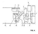
- the sector gear 18 has a first and a second position. In the first position, the sector gear 18 locks the locking lever 9 in the in FIG. 3 shown position. In the other position, which is a different pivot position, the locking lever 9 is free and can be around the axle 11 in the in FIG. 4 shown position to be pivoted.
- the locking lever 9 has at a distance from the journal 11 each have a recess 10, in accordance with each FIG. 3 a foot 8 of a locking element 6 engages. Is the locking lever 9 according FIG. 3 locked by the sector gear 18, the two locking pins 6 can not be moved down. By depressing the trigger member 3 thus the two locking pins 6 can be biased. The provided springs are not shown here. If the locking lever 9, however, free, so the two locking pins 6 in consequence of said bias in the in FIG. 4 shown lower position to be moved. The locking pins 6 are in this case in a guide part 7 ( Fig. 4 ) slidably guided. In this position, the locking pins 6 no longer protrude into the rotor of the rotary lock cylinder and thus release it.
- the locking lever 9 is in the in FIG. 4 shown pivot position locked by the downwardly moved locking pins 6 by the stop of the feet 8 at one approach 22.
- the locking lever 9 can thus only in the in FIG. 3 shown starting position to be pivoted when the key is removed and the trigger member 3 and the two locking pins 6 by a spring, not shown here back up into the in FIG. 3 shown position to be moved. Does the locking lever 9 in FIG. 3 achieved position shown, it is locked by a corresponding pivoting movement of the toothed segment 18 again. The two locking pins 6 can then no longer be moved down.
- a holding contact B which has a contact element 16 which has a first tongue 16a and a longer second tongue 16b.
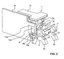
- These tongues 16a and 16b are in accordance with FIG. 5 attached to a web 16c, with which the contact element 16 is attached to a web 23 of the locking lever 9, as the FIG. 2 shows.
- the contact element 16 is latched in particular with the web 16c on the locking lever 9.
- the contact element 16 connects the two contacts 17a and 17b with each other.
- the contact element 16 is located in the in FIG. 2 shown lower position, so only the first tongue 16a is still in contact with the first contact 17a.
- the contact between the second tongue 16b and the second contact 17b is canceled.
- the motor 4 can be switched by the electronic circuit E.
- the holding contact B thus ensures that the toothed segment 18 is pivoted by the motor 4 only in the locked position when the locking lever 9 after removal of the key in the FIG. 3 has reached shown position.
- the holding contact B or holding switch is realized here by electrical contacts. In principle, however, the holding contact B could also be realized, for example, by means of sensors, for example with a Hall sensor.
- the inventive actuator 1 can be made of a few and robust parts and with a largely rigid and positive Kraflübertragung. An opening by vibration can be avoided. Since it is ensured by said holding contact that after removing the key in the intended time, the locking pins 6 are locked again, also results in a high reliability.
Landscapes
- Physics & Mathematics (AREA)
- Electromagnetism (AREA)
- Lock And Its Accessories (AREA)
Description
- Die Erfindung betrifft einen Aktuator nach dem Oberbegriff des Ansrpuchs 1.
- Ein Aktuator dieser Gattung sowie ein elektromechanischer Drehschliesszylinder mit einem solchen Aktuator ist in der Internationalen Patentanmeldung
PCT/CH 2006/000695 WO 2007/073608 ) vom 13. Dezember 2006 des Anmelders offenbart. Der Drehschliesszylinder besitzt wie üblich einen Stator und einen Rotor sowie Zuhaltungen. Zusätzlich zu den Zuhaltungen besitzt der Drehschliesszylinder zwei Sperrstifte, die in der Sperrstellung durch den Aktuator gesperrt sind, so dass diese Sperrstifte erst dann zur Freigabe des Motors bewegt werden können, wenn der Aktuator diese frei gibt. Beim Einsetzen eines Schlüssels in den Schlüsselkanal des Drehschliesszylinders wird durch den Schlüssel ein Drückerorgan nach unten bewegt und die Sperrstifte werden durch eine Feder dadurch vorgespannt. Die Sperrstifte können jedoch noch nicht bewegt werden, das sie wie erwähnt gesperrt sind. Wir der Schlüssel von der elektronischen Schaltung nach dem Lesen eines Codes als berechtigt erkannt, so gibt der Aktuator die Sperrstifte frei. Infolge der Vorspannung durch das Drückerorgan werden die Sperrstifte in eine freigebende Position bewegt, so dass der Rotor gedreht und das Schloss geöffnet werden kann. Die elektronische Schaltung fällt nach dem Betätigen des Motors sofort wieder in einen "sleep modus". Wird der Schlüssel abgezogen, so geht das Drückerorgan durch die Wirkung einer weiteren Feder nach oben in die Ausgangsstellung. Über einen Weckkontakt wird die elektronische Schaltung geweckt und der Motor aktiviert, der hierauf die Sperrstifte wieder sperrt. - Die
US-A-2007/0084259 offenbart einen Schliesszylinder mit einem elektronischen Schlüssel. Ein stabförmiges Sperrelement ist an einem deformierbaren Teil abgestützt, das positionierbar ist, so dass das Sperrelement einen Rotor freigibt oder sperrt. Mittels einer Zutrittsvorrichtung kann der Schliesszylinder von einem freigebenden in einen verriegelten Zustand übergeführt werden. Dies erfolgt alternativ durch Abziehen des Schlüssels oder nach Ablauf einer vorbestimmten Zeitdauer. - Die
EP-A-1 505 229 offenbart einen Schliesszylinder, der einen elektrisch aktivierbaren Sperrmechanismus und einen elektromagnetischen Antrieb zur Verstellung eines Blockierelementes aufweist. Der Antrieb wird von einer elektronischen Steuereinrichtung anhand von Daten eins Transponders gesteuert, der in einem Schlüssel angeordnet ist. Auch hier ist vorgesehen, dass ein entriegelter Schliesszylinder nach einer vorgesehenen Zeitspanne angesteuert wird, um ein Blockierelement in eine Blockierstellung zu bewegen. Dadurch kann verhindert werden, dass der Schliesszylinder unbeabsichtigt lange offen bleibt. - Die
US-A-2004/0035160 betrifft eine Schliessvorrichtung mit einem programmierbaren Schlüssel. Um einen Rotor zu sperren, ist ein Sperrelement vorgesehen, das mit einem Rotor betätigt werden kann. Sind die Schliessvorrichtung und die Tür geöffnet, wird der Schlüssel abgezogen. Das Sperrelement geht danach in seine Ruhestellung zurück und über einen Schalter wird die Stromversorgung unterbrochen. - Die
ES-A-2 808 552 - Der Erfindung liegt die Aufgabe zu Grunde, einen Aktuator der genannten Art zu schaffen, der noch robuster und funktionssicherer arbeitet und der trotzdem vergleichsweise kostengünstig hergestellt werden kann.
- Die Aufgabe ist bei einem gattungsgemässen Aktuator gemäss Anspruch 1 gelöst. Beim Abziehen des Schlüssels wird somit in einem ersten Schritt die elektronische Schaltung aufgeweckt und dann verzögert der Motor eingeschaltet, um über die genannte Sperrvorrichtung den wenigstens einen Sperrstift wieder zu verriegeln. Damit kann auch bei sehr robuster und starrer Ausbildung des Aktuators vermieden werden, dass der Motor zu früh eingeschaltet wird und die Sperrvorrichtung verklemmt. Dadurch ist insbesondere eine starre und kompakte Ausführung möglich, die ein Aufklopfen verhindert.
- Die Haltemittel weisen erfindungsgemäss ein Kontaktelement auf, dass an der Sperrvorrichtung gelagert und mit dieser verschwenkbar ist. Das Kontaktelement bildet somit ein Schaltelement mit zwei Positionen. In der einen Position ist der Schalter geschlossen und in der anderen geöffnet.
- Vorzugsweise ist das Kontaktelement an einem Sperrhebel gelagert, der mit dem genannten Sperrstift zusammenarbeitet um diesen zu sperren bzw. frei zu geben.
- Nach einer Weiterbildung der Erfindung weist das Kontaktelement zwei Kontaktzungen auf, die in einer ersten Position zwei Kontakte der elektronischen Schaltung überbrücken und damit den Motor im genannten Ruhezustand halten und in einer zweiten Position die genannten Kontakte nicht überbrücken. Die erste Position ist die Halteposition und die zweite Position diejenige nach der genannten Zeitdauer.
- Nach einer Weiterbildung der Erfindung ist vorgesehen, dass die Sperrvorrichtung einen schwenkbaren Sperrhebel und ein Zahnsegment aufweist, wobei das Zahnsegment zwischen dem Motor und dem Sperrhebel angeordnet ist, wobei der Sperrhebel in einer ersten Position den genannten wenigstens einen Sperrstift sperrt und in einer zweiten Position freigibt.
- Die Erfindung betrifft zudem einen elektromechanischen Drehschliesszylinder mit einem solchen Aktuator. Der Aktuator bildet mit einem Drückerorgan eine Einheit. Das Drückerorgan kann mit dem vorderen Ende eines Schlüssels zum Vorspannen des wenigstens einen Sperrstiftes nach unten bewegt werden. Die Sperrvorrichtung hat hierbei lediglich die Funktion, den Sperrstift zu sperren bzw. frei zu geben. Die Energie zum Bewegen des Sperrstiftes wird vom Benutzer aufgebracht, indem er das Drückerorgan mit dem Schlüssel nach unten bewegt. Der Energieverbrauch zum Betrieb des Motors kann deshalb minimal gehalten werden. Eine Batterie, mit welcher der Motor gespiesen wird, kann eine entsprechend längere Lebensdauer aufweisen.
- Nach einer Weiterbildung der Erfindung ist vorgesehen, dass der Weckkontakt mit einem Kontaktelement geschaltet wird, das mit dem Drückerorgan verbunden ist und mit diesem nach unten sowie nach oben bewegbar ist. Dieses Kontaktelement ist vorzugsweise so ausgebildet, dass es mit dem Schlüssel oder einem gesonderten Schlüssel kontaktierbar ist. Dieser Kontakt kann als Programmierkontakt, zur Notspeisung oder auch für andere Zwecke verwendet werden.
- Nach einer Weiterbildung der Erfindung ist der Weckkontakt auf einer ersten Leiterplatte und der Haltekontakt auf einer zweiten Leiterplatte angeordnet. Dies ermöglicht eine kostengünstige und dennoch funktionssichere Ausführung. Die erste Leiterplatte und/oder die zweite Leiterplatte sind in ein Gehäuse des Aktuators eingesetzt. Dies ermöglicht eine sehr einfache und dennoch präzise Positionierung der Leiterplatten bezüglich des Haltekontaktes.
- Weitere vorteilhafte Merkmale ergeben sich aus den abhängigen Patentansprüchen, der nachfolgenden Beschreibung sowie der Zeichnung.
- Ausführungsbeispiele der Erfindung werden nachfolgend anhand der Zeichnung näher erläutert. Es zeigen:
- Figur 1
- schematisch eine räumliche Ansicht eines erfindungsgemässen Aktuators,
- Figur 2
- eine weitere räumliche Ansicht des erfindungsgemässen Aktuators,
- Figur 3
- eine weitere Ansicht des erfindungsgemässen Aktuators, wobei dieser in der Sperrstellung gezeigt ist,
- Figur 4
- eine Ansicht gemäss
Figur 3 , wobei der Aktuator hier in der entsperrten Position gezeigt ist und - Figur 5
- eine räumliche Ansicht eines Kontaktelements.
- Die
Figur 1 zeigt einen Aktuator 1, der ein Gehäuse 2 aufweist, das einen Gehäuseoberteil 2a und einen Gehäuseanteil 2b besitzt und in dem ein Elektromotor 4 gelagert ist. Die Speisung des Elektromotors 4 erfolgt beispielsweise über eine hier nicht gezeigte Batterie, die über Kontakte 5 mit dem Elektromotor 4 elektrisch verbunden ist. Im Gehäuse 2 ist zudem ein Drückerorgan 3 gelagert, das einen hinteren Teil 3a und einen vorderen Teil 3b aufweist, die bei montiertem Aktuator 1 in den Schlüsselkanal eines hier nicht gezeigten elektromechanischen Drehschliesszylinders eingreifen. Mit diesem Drückerorgan 3 können zwei Sperrstifte 6 durch einschieben eines hier nicht gezeigten Schlüssels in den Schlüsselkanal vorgespannt werden. Mit einem Sperrhebel 9 können die beiden Sperrstifte 6 gemässFigur 3 gesperrt werden, so dass sie beim Vorspannen in der ursprünglichen Position verbleiben. Zur Offenbarung des grundsätzlichen Aufbaues eines solchen Aktuators und eines elektromechanischen Drehschliesszylinders wird auf die bereits erwähntePCT/CH 2006/000695 - Der Aktuator 1 besitzt eine elektronische Schaltung E, die gemäss der
Figur 1 eine erste Leiterplatte 13 und eine zweite Leiterplatte 14 besitzt. Über der ersten Leiterplatte 13 sind zwei Kontaktzungen 15 angeordnet, die mit der ersten Leiterplatte 13 einen Weckschalter A bilden. Die Kontaktzungen 15 sind wie ersichtlich zuerst nach unten und dann nach oben gebogen und bilden schliesslich eine Kontaktfläche 15a die am oberen Ende des vorderen Teils 3b angeordnet ist. Wird das Drückerorgan 3 durch Einsetzen eines Schlüsselschaftes in den Schlüsselkanal nach unten bewegt, so bewegen sich auch die beiden Kontaktzungen 15 nach unten und schliessen den Weckschalter A. Dadurch wird die elektronische Schaltung E aufgeweckt und nach einer Überprüfung des Schlüsselcodes der Motor 4 eingeschaltet. Dieser dreht ein inFigur 3 lediglich angedeutetes Schneckenrad 21, das mit der Achse des Motors 4 verbunden und mit einem Zahnsegment 18 in Eingriff ist sowie mit Zahnungen 19. Das Zahnsegment 18 schwenkbar ist mit Achszapfen 20 begrenzt verschwenkbar im Gehäuse 2 gelagert und über dem Sperrhebel 9 angeordnet, der ebenfalls über Achszapfen 11 begrenzt in Ausnehmungen 12 (Fig. 1 ) des Gehäuses 2 gelagert ist. Das Zahnsegment 18 besitzt eine erste und eine zweite Position. In der ersten Position sperrt das Zahnsegment 18 den Sperrhebel 9 in der inFigur 3 gezeigten Position. In der anderen Position, die eine andere Schwenkposition ist, ist der Sperrhebel 9 frei und kann um die Achszapfen 11 in die inFigur 4 gezeigte Stellung verschwenkt werden. - Der Sperrhebel 9 besitzt im Abstand zu den Achszapfen 11 jeweils eine Ausnehmung 10, in die jeweils gemäss
Figur 3 ein Fuss 8 eines Sperrelementes 6 eingreift. Ist der Sperrhebel 9 gemässFigur 3 durch das Zahnsegment 18 gesperrt, so können die beiden Sperrstifte 6 nicht nach unten bewegt werden. Durch Niederdrücken des Drückerorgans 3 können somit die beiden Sperrstifte 6 vorgespannt werden. Die vorgesehenen Federn sind hier nicht gezeigt. Ist der Sperrhebel 9 hingegen frei, so können die beiden Sperrstifte 6 in Folge der genannten Vorspannung in die inFigur 4 gezeigte untere Stellung bewegt werden. Die Sperrstifte 6 sind hierbei in einem Führungsteil 7 (Fig. 4 ) verschieblich geführt. In dieser Stellung ragen die Sperrstifte 6 nicht mehr in den Rotor des Drehschliesszylinders und geben diesen somit frei. Der Sperrhebel 9 wird in der inFigur 4 gezeigten Schwenkposition durch die nach unten bewegten Sperrstifte 6 durch den Anschlag der Füsse 8 an jeweils einem Ansatz 22 gesperrt. Der Sperrhebel 9 kann somit erst dann in die inFigur 3 gezeigte Ausgangsstellung verschwenkt werden, wenn der Schlüssel abgezogen und das Drückerorgan 3 sowie die beiden Sperrstifte 6 durch eine hier nicht gezeigte Feder wieder nach oben in die inFigur 3 gezeigte Stellung bewegt werden. Hat der Sperrhebel 9 die inFigur 3 gezeigte Stellung erreicht, so wird er durch eine entsprechende Schwenkbewegung des Zahnsegmentes 18 wieder gesperrt. Die beiden Sperrstifte 6 können dann somit nicht mehr nach unten bewegt werden. - Damit der Motor 4 das Zahnsegment 18 erst dann verschwenkt, wenn der Sperrhebel 9 sich in der in
Figur 3 gezeigten Stellung befindet, ist ein Haltekontakt B vorgesehen, der ein Kontaktelement 16 aufweist, das eine erste Zunge 16a und eine längere zweite Zunge 16b besitzt. Diese Zungen 16a und 16b sind gemäss derFigur 5 an einem Steg 16c angebracht, mit dem das Kontaktelement 16 an einem Steg 23 des Sperrhebels 9 befestigt ist, wie dieFigur 2 zeigt. Das Kontaktelement 16 ist insbesondere mit dem Steg 16c auf den Sperrhebel 9 aufgerastet. Beim Verschwenken des Sperrhebels 9 schleifen die beiden Zungen 16a und 16b an einem ersten Kontakt 17a bzw. an einem zweiten Kontakt 17b der Leiterplatte 14. In der Stellung des Sperrhebels 9 gemässFigur 4 verbindet das Kontaktelement 16 die beiden Kontakte 17a und 17b miteinander. Durch diese elektrische Überbrückung der beiden Kontakte wird über die elektronische Schaltung E der Motor 4 in der Ruhestellung gehalten. Auch beim Aufwecken der elektronischen Schaltung E kann der Motor 4 deshalb nicht eingeschaltet werden. Befindet sich das Kontaktelement 16 jedoch in der inFigur 2 gezeigten unteren Position, so ist lediglich noch die erste Zunge 16a mit dem ersten Kontakt 17a in Kontakt. Der Kontakt zwischen der zweiten Zunge 16b und dem zweiten Kontakt 17b ist hingegen aufgehoben. In dieser Schaltposition kann der Motor 4 von der elektronischen Schaltung E geschaltet werden. Vor dem Erreichen dieser Position jedoch nicht. Der Haltekontakt B stellt damit sicher, dass das Zahnsegment 18 durch den Motor 4 erst dann in die Sperrposition verschwenkt wird, wenn der Sperrhebel 9 nach dem Abziehen des Schlüssels die inFigur 3 gezeigte Stellung erreicht hat. Der Haltekontakt B bzw. Halteschalter ist hier durch elektrische Kontakte realisiert. Grundsätzlich könnte der Haltekontakt B aber auch beispielsweise mittels Sensoren beispielsweise mit einem Hallsensor realisiert werden. - Der erfindungsgemässe Aktuator 1 kann aus wenigen und robusten Teilen und mit einer weitgehend starren und formschlüssigen Kraflübertragung hergestellt werden. Eine Öffnung durch Vibration kann dadurch vermieden werden. Da durch den genannten Haltekontakt sichergestellt ist, dass nach dem Abziehen des Schlüssels im vorgesehenen Zeitpunkt die Sperrstifte 6 wieder verriegelt werden, ergibt sich zudem eine hohe Funktionssicherheit.
Bezugszeichenliste 1 Aktuator 15a Kontaktfläche 2 Gehäuse 16 Kontaktelement 2a Gehäuseoberteil 16a erste Zunge 2b Gehäuseunterteil 16b zweite Zunge 3 Drückerorgan 16c Steg 3a hinterer Teil 17 Kontakte 3b vorderer Teil 17a erster Kontakt 4 Motor 17b zweiter Kontakt 5 Anschlüsse 18 Zahnsegment 6 Sperrstifte 19 Zahnung 7 Führungsteil 20 Achszapfen 8 Fuss 21 Schneckenrad 9 Sperrhebel 22 Ansatz 10 Ausnehmung 23 Steg 11 Achszapfen 12 Ausnehmung A Weckschalter 13 Leiterplatte B Haltekontakt 14 Leiterplatte E elektronische Schaltung 15 Kontaktzungen
Claims (9)
- Aktuator (1) für einen elektromechanischen Drehschliesszylinder, mit einem Motor (4), einer elektronischen Schaltung (E), wenigstens einem Sperrstift (6), und einer Sperrvorrichtung (18,9), mit welcher der wenigstens eine Sperrstift (6) über den Motor (4) in einer Sperrposition sperrbar ist, wobei die elektronische Schaltung (E) einen Weckkontakt (A) zur Weckung der Schaltung (E) aufweist, dadurch gekennzeichnet, dass Haltemittel (B) vorgesehen sind, die nach einem Öffnen des Weckkontaktes (A) beim Abziehen eines Schlüssels ein verfrühtes Einschalten des Motors (4) verhindern, wobei die Haltemittel (B) ein Kontaktelement (16) aufweisen, das an der Sperrvorrichtung (18,9) gelagert und mit dieser verschwenkbar ist.
- Aktuator nach Anspruch 1, dadurch gekennzeichnet, dass das Kontaktelement (16) an einem Sperrhebel (9) gelagert ist, der schwenkbar gelagert ist und der zum Sperren des wenigstens einen Sperrstifts (6) vorgesehen ist.
- Aktuator nach einem der Ansprüche 1 bis 2, dadurch gekennzeichnet, dass das Kontaktelement (16) zwei Kontaktzungen (16a,16b) aufweist, die in einer ersten Position zwei Kontakte (17a,17b) der elektronischen Schaltung (E) überbrücken und damit die elektronische Schaltung (E) in einen "sleep modus" halten und die in einer zweiten Position die genannten Kontakte nicht überbrücken.
- Aktuator nach einem der Ansprüche 1 bis 3, dadurch gekennzeichnet, dass die Sperrvorrichtung (18,9) einen schwenkbaren Sperrhebel (9) und ein Zahnsegment (18) aufweist, wobei das Zahnsegment (18) zwischen dem Motor (4) und dem Sperrhebel (9) angeordnet ist und der Sperrhebel (9) in einer ersten Position sperrt und in einer zweiten Position freigibt.
- Elektromechanischer Drehschliesszylinder mit einem Aktuator (1) nach einem der Ansprüche 1 bis 5, dadurch gekennzeichnet, dass der Aktuator (1) mit einem Drückerorgan (3) eine Einheit bildet und das Drückerorgan (3) mit dem vorderen Ende eines Schlüssels zum Vorspannen des wenigstens einen Sperrstifts (6) nach unten bewegbar ist.
- Elektromechanischer Drehschliesszylinder nach Anspruch 5, dadurch gekennzeichnet, dass der wenigstens eine Sperrstift (6) einen Fuss (8) aufweist, der in einer Sperrstellung in eine Ausnehmung (10) eines Sperrhebels (9) eingreift.
- Elektromechanischer Drehschliesszylinder nach Anspruch 5 oder 6, dadurch gekennzeichnet, dass der Weckkontakt (A) mit einem Kontaktelement (15a) geschaltet wird, das mit dem Drückerorgan (3) verbunden ist und mit diesem nach unten und nach oben bewegbar ist.
- Elektromechanischer Drehzylinder nach einem der Ansprüche 5 bis 7, dadurch gekennzeichnet, dass der Weckkontakt (A) auf einer ersten Leiterplatte (13) und der Haltekontakt (B) auf einer zweiten Leiterplatte (14) angeordnet ist.
- Elektromechanischer Drehzylinder nach Anspruch 8, dadurch gekennzeichnet, dass die erste Leiterplatte (13) und/oder die zweite Leiterplatte (14) in ein Gehäuse (2) des Aktuators (1) eingesetzt und in diesem positioniert sind.
Applications Claiming Priority (2)
| Application Number | Priority Date | Filing Date | Title |
|---|---|---|---|
| CH19502007 | 2007-12-17 | ||
| PCT/CH2008/000509 WO2009076784A1 (de) | 2007-12-17 | 2008-12-03 | Aktuator für einen elektromechanischen drehschliesszylinder und einen elektromechanischen drehschliesszylinder mit einem solchen aktuator |
Publications (2)
| Publication Number | Publication Date |
|---|---|
| EP2231970A1 EP2231970A1 (de) | 2010-09-29 |
| EP2231970B1 true EP2231970B1 (de) | 2014-01-22 |
Family
ID=39338123
Family Applications (1)
| Application Number | Title | Priority Date | Filing Date |
|---|---|---|---|
| EP08861078.7A Not-in-force EP2231970B1 (de) | 2007-12-17 | 2008-12-03 | Aktuator für einen elektromechanischen drehschliesszylinder und einen elektromechanischen drehschliesszylinder mit einem solchen aktuator |
Country Status (3)
| Country | Link |
|---|---|
| EP (1) | EP2231970B1 (de) |
| CN (1) | CN101903608A (de) |
| WO (1) | WO2009076784A1 (de) |
Citations (1)
| Publication number | Priority date | Publication date | Assignee | Title |
|---|---|---|---|---|
| US4901545A (en) * | 1987-12-28 | 1990-02-20 | Rising Star Technologies (A Partnership) | Self-contained electromechanical locking device |
Family Cites Families (7)
| Publication number | Priority date | Publication date | Assignee | Title |
|---|---|---|---|---|
| ES2046123B1 (es) * | 1992-06-05 | 1996-12-16 | Azbe B Zubia S A | Cerradura electronico-mecanica. |
| DE19756341B4 (de) * | 1997-12-18 | 2007-08-23 | Marquardt Gmbh | Schließsystem, insbesondere für Kraftfahrzeuge |
| FR2808552B1 (fr) | 2000-05-04 | 2003-06-13 | Vachette Sa | Serrure a deverrouillage mecanique et electrique |
| US7334443B2 (en) | 2002-02-22 | 2008-02-26 | Master Lock Company Llc | Radio frequency electronic lock |
| DE10335917A1 (de) | 2003-08-06 | 2005-03-03 | Aug. Winkhaus Gmbh & Co. Kg | Schließzylinder |
| US7640773B2 (en) | 2005-10-19 | 2010-01-05 | Ge Security, Inc. | Lock portion with deformable features |
| AU2006331309B2 (en) | 2005-12-27 | 2011-06-02 | Keso Ag | Electromechanical rotary lock cylinder |
-
2008
- 2008-12-03 WO PCT/CH2008/000509 patent/WO2009076784A1/de not_active Ceased
- 2008-12-03 CN CN2008801211638A patent/CN101903608A/zh active Pending
- 2008-12-03 EP EP08861078.7A patent/EP2231970B1/de not_active Not-in-force
Patent Citations (1)
| Publication number | Priority date | Publication date | Assignee | Title |
|---|---|---|---|---|
| US4901545A (en) * | 1987-12-28 | 1990-02-20 | Rising Star Technologies (A Partnership) | Self-contained electromechanical locking device |
Also Published As
| Publication number | Publication date |
|---|---|
| WO2009076784A1 (de) | 2009-06-25 |
| EP2231970A1 (de) | 2010-09-29 |
| CN101903608A (zh) | 2010-12-01 |
Similar Documents
| Publication | Publication Date | Title |
|---|---|---|
| DE69914045T2 (de) | Kraftfahrzeugtürschloss mit innerer und/oder äusserer elektrischer Verriegelungs-/Entriegelungsvorrichtung | |
| DE69106666T2 (de) | Elektromechanisches Türschloss. | |
| DE69820116T2 (de) | Mechanisch und elektronisch betätigbare schlüsselzylindereinheit für schlösser | |
| DE10112787B4 (de) | Türverriegelungssystem für ein Fahrzeug | |
| DE19622028C2 (de) | Fahrzeugtürsperrvorrichtung | |
| WO2005001224A1 (de) | Elektromechanischer schliesszylinder | |
| DE10029059C2 (de) | Schließvorrichtung | |
| DE3638305A1 (de) | Schliessmechanismus zur sicherung des kofferraumdeckels eines kraftfahrzeuges | |
| DE112016002502T5 (de) | Türverriegelungssystem | |
| DE69001255T2 (de) | Schloss fuer die tuer eines kraftfahrzeuges. | |
| DE4417804A1 (de) | Türverriegelungsvorrichtung mit einem Antidiebstahlmechanismus | |
| EP1737713B1 (de) | Vorrichtung zum starten eines fahrzeugmotors mittels eines elektronischen schlüssels und ein dazu zu verwendender schlüssel | |
| DE69617446T2 (de) | Verriegelungseinheit | |
| DE3137260C2 (de) | ||
| EP1419944B1 (de) | Zündschlosssystem für ein Kraftfahrzeug | |
| DE69511357T2 (de) | Elektrisch betätigtes Autotürschloss | |
| EP2239401B1 (de) | Elektro-mechanischer Drehschliesszylinder | |
| DE69300108T2 (de) | Mechanisches Schloss. | |
| EP1135284A1 (de) | Schliessystem, insbesondere für kraftfahrzeuge | |
| EP1577468B1 (de) | Abdeckvorrichtung für eine Schliesseinrichtung | |
| EP1837463B1 (de) | Elektrischer Türöffner | |
| DE19604644C2 (de) | Schließvorrichtung | |
| EP1997986B1 (de) | Schloss, insbesondere Panikschloss mit Nussbetätigungsstellungssensor | |
| DE69416990T2 (de) | Türdrückeranordnung | |
| DE102004034529B3 (de) | Elektromechanisches Türschloss |
Legal Events
| Date | Code | Title | Description |
|---|---|---|---|
| PUAI | Public reference made under article 153(3) epc to a published international application that has entered the european phase |
Free format text: ORIGINAL CODE: 0009012 |
|
| 17P | Request for examination filed |
Effective date: 20100518 |
|
| AK | Designated contracting states |
Kind code of ref document: A1 Designated state(s): AT BE BG CH CY CZ DE DK EE ES FI FR GB GR HR HU IE IS IT LI LT LU LV MC MT NL NO PL PT RO SE SI SK TR |
|
| AX | Request for extension of the european patent |
Extension state: AL BA MK RS |
|
| REG | Reference to a national code |
Ref country code: HK Ref legal event code: DE Ref document number: 1144454 Country of ref document: HK |
|
| DAX | Request for extension of the european patent (deleted) | ||
| 17Q | First examination report despatched |
Effective date: 20120427 |
|
| GRAP | Despatch of communication of intention to grant a patent |
Free format text: ORIGINAL CODE: EPIDOSNIGR1 |
|
| INTG | Intention to grant announced |
Effective date: 20130730 |
|
| RAP1 | Party data changed (applicant data changed or rights of an application transferred) |
Owner name: ASSA ABLOY (SCHWEIZ) AG |
|
| GRAS | Grant fee paid |
Free format text: ORIGINAL CODE: EPIDOSNIGR3 |
|
| GRAA | (expected) grant |
Free format text: ORIGINAL CODE: 0009210 |
|
| AK | Designated contracting states |
Kind code of ref document: B1 Designated state(s): AT BE BG CH CY CZ DE DK EE ES FI FR GB GR HR HU IE IS IT LI LT LU LV MC MT NL NO PL PT RO SE SI SK TR |
|
| REG | Reference to a national code |
Ref country code: GB Ref legal event code: FG4D Free format text: NOT ENGLISH |
|
| REG | Reference to a national code |
Ref country code: CH Ref legal event code: EP |
|
| REG | Reference to a national code |
Ref country code: CH Ref legal event code: NV Representative=s name: ISLER AND PEDRAZZINI AG, CH |
|
| REG | Reference to a national code |
Ref country code: AT Ref legal event code: REF Ref document number: 650919 Country of ref document: AT Kind code of ref document: T Effective date: 20140215 |
|
| REG | Reference to a national code |
Ref country code: IE Ref legal event code: FG4D Free format text: LANGUAGE OF EP DOCUMENT: GERMAN |
|
| REG | Reference to a national code |
Ref country code: DE Ref legal event code: R096 Ref document number: 502008011279 Country of ref document: DE Effective date: 20140313 |
|
| REG | Reference to a national code |
Ref country code: NL Ref legal event code: T3 |
|
| REG | Reference to a national code |
Ref country code: LT Ref legal event code: MG4D |
|
| PG25 | Lapsed in a contracting state [announced via postgrant information from national office to epo] |
Ref country code: IS Free format text: LAPSE BECAUSE OF FAILURE TO SUBMIT A TRANSLATION OF THE DESCRIPTION OR TO PAY THE FEE WITHIN THE PRESCRIBED TIME-LIMIT Effective date: 20140522 Ref country code: LT Free format text: LAPSE BECAUSE OF FAILURE TO SUBMIT A TRANSLATION OF THE DESCRIPTION OR TO PAY THE FEE WITHIN THE PRESCRIBED TIME-LIMIT Effective date: 20140122 Ref country code: NO Free format text: LAPSE BECAUSE OF FAILURE TO SUBMIT A TRANSLATION OF THE DESCRIPTION OR TO PAY THE FEE WITHIN THE PRESCRIBED TIME-LIMIT Effective date: 20140422 |
|
| PG25 | Lapsed in a contracting state [announced via postgrant information from national office to epo] |
Ref country code: PT Free format text: LAPSE BECAUSE OF FAILURE TO SUBMIT A TRANSLATION OF THE DESCRIPTION OR TO PAY THE FEE WITHIN THE PRESCRIBED TIME-LIMIT Effective date: 20140522 Ref country code: FI Free format text: LAPSE BECAUSE OF FAILURE TO SUBMIT A TRANSLATION OF THE DESCRIPTION OR TO PAY THE FEE WITHIN THE PRESCRIBED TIME-LIMIT Effective date: 20140122 Ref country code: ES Free format text: LAPSE BECAUSE OF FAILURE TO SUBMIT A TRANSLATION OF THE DESCRIPTION OR TO PAY THE FEE WITHIN THE PRESCRIBED TIME-LIMIT Effective date: 20140122 Ref country code: SE Free format text: LAPSE BECAUSE OF FAILURE TO SUBMIT A TRANSLATION OF THE DESCRIPTION OR TO PAY THE FEE WITHIN THE PRESCRIBED TIME-LIMIT Effective date: 20140122 Ref country code: CY Free format text: LAPSE BECAUSE OF FAILURE TO SUBMIT A TRANSLATION OF THE DESCRIPTION OR TO PAY THE FEE WITHIN THE PRESCRIBED TIME-LIMIT Effective date: 20140122 |
|
| PG25 | Lapsed in a contracting state [announced via postgrant information from national office to epo] |
Ref country code: LV Free format text: LAPSE BECAUSE OF FAILURE TO SUBMIT A TRANSLATION OF THE DESCRIPTION OR TO PAY THE FEE WITHIN THE PRESCRIBED TIME-LIMIT Effective date: 20140122 Ref country code: HR Free format text: LAPSE BECAUSE OF FAILURE TO SUBMIT A TRANSLATION OF THE DESCRIPTION OR TO PAY THE FEE WITHIN THE PRESCRIBED TIME-LIMIT Effective date: 20140122 |
|
| REG | Reference to a national code |
Ref country code: DE Ref legal event code: R097 Ref document number: 502008011279 Country of ref document: DE |
|
| PG25 | Lapsed in a contracting state [announced via postgrant information from national office to epo] |
Ref country code: EE Free format text: LAPSE BECAUSE OF FAILURE TO SUBMIT A TRANSLATION OF THE DESCRIPTION OR TO PAY THE FEE WITHIN THE PRESCRIBED TIME-LIMIT Effective date: 20140122 Ref country code: CZ Free format text: LAPSE BECAUSE OF FAILURE TO SUBMIT A TRANSLATION OF THE DESCRIPTION OR TO PAY THE FEE WITHIN THE PRESCRIBED TIME-LIMIT Effective date: 20140122 Ref country code: DK Free format text: LAPSE BECAUSE OF FAILURE TO SUBMIT A TRANSLATION OF THE DESCRIPTION OR TO PAY THE FEE WITHIN THE PRESCRIBED TIME-LIMIT Effective date: 20140122 Ref country code: RO Free format text: LAPSE BECAUSE OF FAILURE TO SUBMIT A TRANSLATION OF THE DESCRIPTION OR TO PAY THE FEE WITHIN THE PRESCRIBED TIME-LIMIT Effective date: 20140122 |
|
| PG25 | Lapsed in a contracting state [announced via postgrant information from national office to epo] |
Ref country code: SK Free format text: LAPSE BECAUSE OF FAILURE TO SUBMIT A TRANSLATION OF THE DESCRIPTION OR TO PAY THE FEE WITHIN THE PRESCRIBED TIME-LIMIT Effective date: 20140122 Ref country code: PL Free format text: LAPSE BECAUSE OF FAILURE TO SUBMIT A TRANSLATION OF THE DESCRIPTION OR TO PAY THE FEE WITHIN THE PRESCRIBED TIME-LIMIT Effective date: 20140122 |
|
| PLBE | No opposition filed within time limit |
Free format text: ORIGINAL CODE: 0009261 |
|
| STAA | Information on the status of an ep patent application or granted ep patent |
Free format text: STATUS: NO OPPOSITION FILED WITHIN TIME LIMIT |
|
| 26N | No opposition filed |
Effective date: 20141023 |
|
| REG | Reference to a national code |
Ref country code: DE Ref legal event code: R097 Ref document number: 502008011279 Country of ref document: DE Effective date: 20141023 |
|
| PG25 | Lapsed in a contracting state [announced via postgrant information from national office to epo] |
Ref country code: SI Free format text: LAPSE BECAUSE OF FAILURE TO SUBMIT A TRANSLATION OF THE DESCRIPTION OR TO PAY THE FEE WITHIN THE PRESCRIBED TIME-LIMIT Effective date: 20140122 |
|
| PG25 | Lapsed in a contracting state [announced via postgrant information from national office to epo] |
Ref country code: BE Free format text: LAPSE BECAUSE OF NON-PAYMENT OF DUE FEES Effective date: 20141231 |
|
| PG25 | Lapsed in a contracting state [announced via postgrant information from national office to epo] |
Ref country code: LU Free format text: LAPSE BECAUSE OF FAILURE TO SUBMIT A TRANSLATION OF THE DESCRIPTION OR TO PAY THE FEE WITHIN THE PRESCRIBED TIME-LIMIT Effective date: 20141203 |
|
| GBPC | Gb: european patent ceased through non-payment of renewal fee |
Effective date: 20141203 |
|
| REG | Reference to a national code |
Ref country code: IE Ref legal event code: MM4A |
|
| PG25 | Lapsed in a contracting state [announced via postgrant information from national office to epo] |
Ref country code: GB Free format text: LAPSE BECAUSE OF NON-PAYMENT OF DUE FEES Effective date: 20141203 Ref country code: IE Free format text: LAPSE BECAUSE OF NON-PAYMENT OF DUE FEES Effective date: 20141203 |
|
| REG | Reference to a national code |
Ref country code: FR Ref legal event code: PLFP Year of fee payment: 8 |
|
| PGFP | Annual fee paid to national office [announced via postgrant information from national office to epo] |
Ref country code: CH Payment date: 20151211 Year of fee payment: 8 Ref country code: DE Payment date: 20151125 Year of fee payment: 8 |
|
| PGFP | Annual fee paid to national office [announced via postgrant information from national office to epo] |
Ref country code: AT Payment date: 20151125 Year of fee payment: 8 Ref country code: NL Payment date: 20151210 Year of fee payment: 8 |
|
| PGFP | Annual fee paid to national office [announced via postgrant information from national office to epo] |
Ref country code: IT Payment date: 20151221 Year of fee payment: 8 |
|
| PG25 | Lapsed in a contracting state [announced via postgrant information from national office to epo] |
Ref country code: MC Free format text: LAPSE BECAUSE OF FAILURE TO SUBMIT A TRANSLATION OF THE DESCRIPTION OR TO PAY THE FEE WITHIN THE PRESCRIBED TIME-LIMIT Effective date: 20140122 Ref country code: BG Free format text: LAPSE BECAUSE OF FAILURE TO SUBMIT A TRANSLATION OF THE DESCRIPTION OR TO PAY THE FEE WITHIN THE PRESCRIBED TIME-LIMIT Effective date: 20140122 |
|
| PG25 | Lapsed in a contracting state [announced via postgrant information from national office to epo] |
Ref country code: GR Free format text: LAPSE BECAUSE OF FAILURE TO SUBMIT A TRANSLATION OF THE DESCRIPTION OR TO PAY THE FEE WITHIN THE PRESCRIBED TIME-LIMIT Effective date: 20140423 |
|
| PG25 | Lapsed in a contracting state [announced via postgrant information from national office to epo] |
Ref country code: HU Free format text: LAPSE BECAUSE OF FAILURE TO SUBMIT A TRANSLATION OF THE DESCRIPTION OR TO PAY THE FEE WITHIN THE PRESCRIBED TIME-LIMIT; INVALID AB INITIO Effective date: 20081203 Ref country code: MT Free format text: LAPSE BECAUSE OF FAILURE TO SUBMIT A TRANSLATION OF THE DESCRIPTION OR TO PAY THE FEE WITHIN THE PRESCRIBED TIME-LIMIT Effective date: 20140122 Ref country code: TR Free format text: LAPSE BECAUSE OF FAILURE TO SUBMIT A TRANSLATION OF THE DESCRIPTION OR TO PAY THE FEE WITHIN THE PRESCRIBED TIME-LIMIT Effective date: 20140122 |
|
| REG | Reference to a national code |
Ref country code: FR Ref legal event code: PLFP Year of fee payment: 9 |
|
| PGFP | Annual fee paid to national office [announced via postgrant information from national office to epo] |
Ref country code: FR Payment date: 20161111 Year of fee payment: 9 |
|
| REG | Reference to a national code |
Ref country code: HK Ref legal event code: WD Ref document number: 1144454 Country of ref document: HK |
|
| REG | Reference to a national code |
Ref country code: DE Ref legal event code: R119 Ref document number: 502008011279 Country of ref document: DE |
|
| REG | Reference to a national code |
Ref country code: CH Ref legal event code: PL |
|
| REG | Reference to a national code |
Ref country code: NL Ref legal event code: MM Effective date: 20170101 |
|
| REG | Reference to a national code |
Ref country code: AT Ref legal event code: MM01 Ref document number: 650919 Country of ref document: AT Kind code of ref document: T Effective date: 20161203 |
|
| PG25 | Lapsed in a contracting state [announced via postgrant information from national office to epo] |
Ref country code: NL Free format text: LAPSE BECAUSE OF NON-PAYMENT OF DUE FEES Effective date: 20170101 |
|
| PG25 | Lapsed in a contracting state [announced via postgrant information from national office to epo] |
Ref country code: IT Free format text: LAPSE BECAUSE OF NON-PAYMENT OF DUE FEES Effective date: 20161203 Ref country code: AT Free format text: LAPSE BECAUSE OF NON-PAYMENT OF DUE FEES Effective date: 20161203 Ref country code: LI Free format text: LAPSE BECAUSE OF NON-PAYMENT OF DUE FEES Effective date: 20161231 Ref country code: CH Free format text: LAPSE BECAUSE OF NON-PAYMENT OF DUE FEES Effective date: 20161231 |
|
| PG25 | Lapsed in a contracting state [announced via postgrant information from national office to epo] |
Ref country code: DE Free format text: LAPSE BECAUSE OF NON-PAYMENT OF DUE FEES Effective date: 20170701 |
|
| REG | Reference to a national code |
Ref country code: FR Ref legal event code: ST Effective date: 20180831 |
|
| PG25 | Lapsed in a contracting state [announced via postgrant information from national office to epo] |
Ref country code: FR Free format text: LAPSE BECAUSE OF NON-PAYMENT OF DUE FEES Effective date: 20180102 |