EP1419944B1 - Zündschlosssystem für ein Kraftfahrzeug - Google Patents
Zündschlosssystem für ein Kraftfahrzeug Download PDFInfo
- Publication number
- EP1419944B1 EP1419944B1 EP03026207A EP03026207A EP1419944B1 EP 1419944 B1 EP1419944 B1 EP 1419944B1 EP 03026207 A EP03026207 A EP 03026207A EP 03026207 A EP03026207 A EP 03026207A EP 1419944 B1 EP1419944 B1 EP 1419944B1
- Authority
- EP
- European Patent Office
- Prior art keywords
- key
- locking
- carrier element
- ignition
- movement
- Prior art date
- Legal status (The legal status is an assumption and is not a legal conclusion. Google has not performed a legal analysis and makes no representation as to the accuracy of the status listed.)
- Expired - Lifetime
Links
Images


Classifications
-
- H—ELECTRICITY
- H01—ELECTRIC ELEMENTS
- H01H—ELECTRIC SWITCHES; RELAYS; SELECTORS; EMERGENCY PROTECTIVE DEVICES
- H01H13/00—Switches having rectilinearly-movable operating part or parts adapted for pushing or pulling in one direction only, e.g. push-button switch
- H01H13/50—Switches having rectilinearly-movable operating part or parts adapted for pushing or pulling in one direction only, e.g. push-button switch having a single operating member
- H01H13/56—Switches having rectilinearly-movable operating part or parts adapted for pushing or pulling in one direction only, e.g. push-button switch having a single operating member the contact returning to its original state upon the next application of operating force
- H01H13/562—Switches having rectilinearly-movable operating part or parts adapted for pushing or pulling in one direction only, e.g. push-button switch having a single operating member the contact returning to its original state upon the next application of operating force making use of a heart shaped cam
-
- B—PERFORMING OPERATIONS; TRANSPORTING
- B60—VEHICLES IN GENERAL
- B60R—VEHICLES, VEHICLE FITTINGS, OR VEHICLE PARTS, NOT OTHERWISE PROVIDED FOR
- B60R25/00—Fittings or systems for preventing or indicating unauthorised use or theft of vehicles
- B60R25/01—Fittings or systems for preventing or indicating unauthorised use or theft of vehicles operating on vehicle systems or fittings, e.g. on doors, seats or windscreens
- B60R25/04—Fittings or systems for preventing or indicating unauthorised use or theft of vehicles operating on vehicle systems or fittings, e.g. on doors, seats or windscreens operating on the propulsion system, e.g. engine or drive motor
-
- B—PERFORMING OPERATIONS; TRANSPORTING
- B60—VEHICLES IN GENERAL
- B60R—VEHICLES, VEHICLE FITTINGS, OR VEHICLE PARTS, NOT OTHERWISE PROVIDED FOR
- B60R25/00—Fittings or systems for preventing or indicating unauthorised use or theft of vehicles
- B60R25/20—Means to switch the anti-theft system on or off
- B60R25/2063—Ignition switch geometry
-
- B—PERFORMING OPERATIONS; TRANSPORTING
- B60—VEHICLES IN GENERAL
- B60R—VEHICLES, VEHICLE FITTINGS, OR VEHICLE PARTS, NOT OTHERWISE PROVIDED FOR
- B60R25/00—Fittings or systems for preventing or indicating unauthorised use or theft of vehicles
- B60R25/20—Means to switch the anti-theft system on or off
- B60R25/24—Means to switch the anti-theft system on or off using electronic identifiers containing a code not memorised by the user
- B60R25/248—Electronic key extraction prevention
Definitions
- the invention relates to an ignition lock system according to the preamble of patent claim 1.
- an electronic ignition which is actuated by means of an electronic key.
- the electronic ignition key and the electronic key are components of the anti-tamper ignition system.
- the ignition lock has a receptacle for the key, which is located in a designed as a rotor support element.
- the rotor is manually rotatable by means of the key between an initial and multiple movement positions.
- the ignition function such as the switching on of consumers in the motor vehicle, such as radio, lighting, etc., such as the starting of the motor vehicle o.
- To trigger the function of the rotor acts accordingly in the respective movement position on a switching element.
- This ignition lock has a designed in the manner of a slide carrier element. In a recording on the support member of the key is inserted, so that the support member by means of the key between a starting position and movement positions is linearly movable.
- the invention is based on the object by means of a rectilinear movement of the key, in particular by the user manually; operable ignition lock in such a way that it can be operated in a simple manner.
- the one and another movement position for the support element are each formed as locking positions.
- the two locking positions are determined by the interaction of a latching curve, which may be configured in the manner of a switching heart, with an engaging in the latching cam detent pin which is acted upon in particular by an elastic force.
- two latching curves are arranged one behind the other in the direction of movement of the carrier element.
- a restoring force which can be generated, for example, by means of a compression spring, acts on the carrier element in the direction of the starting position.
- an electronic ignition lock with a formed in the manner of a slide carrier element is known.
- the electronic key can be inserted into a receptacle on the carrier element, so that the carrier element by means of the key between a starting position and movement positions is linearly movable.
- a movement position for the support member is a detent position, which is determined by the interaction of a, in particular in the manner of a switching heart designed latching cam with an engaging in the latching cam, in particular acted upon by an elastic force locking pin.
- a restoring force which is generated in particular by means of a compression spring, acts in the direction of the starting position on the carrier element.
- the ignition lock according to the invention has two formed as locking positions movement positions for the support member, which in turn are determined by the cooperation of the locking cam with the engaging in the locking cam detent pin.
- the restoring force acts in the direction of the starting position on the carrier element even during its movement in the other movement position.
- the insertion of the key and the further operation of the key in the ignition by the user is carried out at the ignition of the invention in a simple manner.
- the operation is perceived by the user as particularly ergonomic, although the arrangement of additional attenuators in the ignition for the movement of the key can be dispensed with.
- the ignition works despite the harsh conditions in the vehicle due to the insensitive switching heart very reliable and fchlerunan vaccination. Further embodiments of the invention are the subject of the dependent claims.
- the support member can be moved by manual operation of the user to yet another position of movement, in which the motor vehicle is then started. Subsequently, after completion of the manual action, the carrier element is automatically returned from the still further movement position into the rest position assigned to the further movement position.
- the operating procedure of such a designed Ignition lock corresponds to the linear movement of that of a conventional ignition, so that the ignition is largely intuitive to use by the user.
- a contour can be arranged such that the latching pin, starting from the starting position along the contour, is always initially directed into the latching position corresponding to a movement position.
- This corresponds to the conventional operating procedure.
- a pressure point is generated shortly before the one movement position, in the overcoming and further movement, the still further movement position can be reached without prior engagement in one movement position. If the movement is not continued at the pressure point, then the carrier element first returns to the one movement position. In one embodiment according to the alternative thus a rapid, instantaneous starting of the motor vehicle is possible.
- the ignition lock has a housing with an opening for the insertion of the key.
- the opening may be closed by the support member in its initial position.
- the receptacle in the support element with the opening corresponds such that a type of cavity is formed in the support member, wherein the cavity is largely completed in the interior of the housing.
- a key-operated, spring-loaded flap can close the receptacle when the key is not inserted.
- a guide for the movement of the carrier element can still be located in the housing, so that a precise movement sequence for the key is provided.
- a pivotable latching lever is arranged on support element, which is loaded with a compression spring.
- the locking lever engages by means of a cam when in the recording befindlichem key in a recess on the key and is still held by means of a locking contour in the housing in befindlichem not in the starting position carrier element in the recess.
- the locking lever is in the initial position of the support member against the force of the compression spring in an interruption of the locking contour so pivotable that the key inserted into the receptacle as well as is removable.
- The weckbare locking lever thus serves to protect the user as trigger safety for the key from the receptacle when the carrier element is not in the starting position and thus the motor vehicle is in operation. To preclude unintentional entanglement o.
- the support member during its movement the support member may have two locking levers arranged on both sides.
- Switching elements can be actuated by the carrier element in the movement positions, so that the switching signal of the respective switching element identifies the associated function.
- the switching element is preferably a Hall sensor, wherein a magnet corresponding to the Hall sensor is arranged on the carrier element.
- a circuit board in the housing of the ignition lock offers.
- the circuit board can be arranged in a space-saving manner approximately parallel to the guide for the support element.
- the circuit board can be inserted in the housing, snapped, clipped o. The like. Be.
- the ignition lock system has a simple, user-friendly linear movement.
- the ignition is simple and inexpensive.
- the ignition is very robust and error-prone despite high functionality.
- the conventional and error-prone hinged cover on the recording of the ignition with a removed key can be dispensed with.
- the Ignition lock system can be made very compact despite high functionality and safety and is therefore easy to accommodate in confined installation spaces in the vehicle.
- the key is substantially completely received in the ignition during driving of the motor vehicle. As a result, a risk of injury by the key for the user's knee in an accident is largely prevented.
- an ignition lock system 1 for a motor vehicle which consists of an electronic ignition lock 3 and an electronic key 2.
- the built-in, for example, in the instrument panel of the motor vehicle ignition 3 has a housing 4.
- the ignition 3 is visible at a visible in Fig. 4 opening 5 in the housing 4 of the key 2 can be inserted.
- the ignition lock 3 has a receptacle 7 for the key 2 located in a carrier element 6.
- the carrier element 6 is manually movable by means of the key 2 between a starting position s1 and successive movement positions s2 to s5, which are indicated in FIG. 5 with corresponding arrows.
- the carrier element 6 is designed to be linearly movable in the manner of a slider.
- the support member 6 is shown in its initial position s1, in which the key 2 in the receptacle 7 can be inserted and removed from the receptacle 7.
- the movement position s2 and the movement position s4 for the support element 6 are each formed as locking positions.
- the two locking positions are determined by the interaction of a designed in the manner of a switching heart locking cam 8, 9 with a locking pin 10.
- the locking pin 10 engages in the latching cam 8, 9 a.
- the locking pin 10 is arranged on a sliding element 34, which in turn is mounted transversely to the direction of movement of the support member 6 on the carrier element 6, as can be seen from FIG. Next, the locking pin 10 is acted upon by the sliding element 34 with an elastic force generated by a spring 35.
- the two locking curves 8, 9 arranged in the direction of movement of the support member 6 in succession in the ignition switch 3, so that the starting position s1 and the positions of movement s2 to s5 follow each other.
- the two locking curves 8, 9 can also be offset from each other or arranged in any other suitable manner.
- the key 2 If the key 2 is inserted into the receptacle 7 and this is then brought together with the carrier element 6 due to manual action of the user on the key 2 from the initial position s1 in one of the positions s2 to s5, it will be between the key 2 and the ignition an electronic code, preferably in a bidirectional communication, exchanged or transmitted. After positive evaluation of the exchanged between the key 2 and the ignition 3 electronic code, i. It is the authorized key 2, at least one of the ignition lock 3 effected function is released and / or triggered. This enabled and / or triggered function can be the switching on of consumers in the motor vehicle, such as the radio, the lighting, etc., the starting of the motor vehicle or the like.
- the electronic code for releasing and / or triggering these functions can during the movement of the support member 6 between the initial position s1 and a movement position s2 to s5, in at least one of the movement positions or even if necessary in other positions, for example, already in the starting position s1, between the key 2 and the ignition switch 3 are exchanged.
- the evaluation of the electronic code can be done in the ignition lock 3 itself or, if desired, in a separate control unit.
- the electronic code can also be transferred from another identification transmitter, such as a separate chip card located at the user, whereby the key 2 then serves merely as a control element in the ignition lock 3 for the user.
- the key 2 is inserted into the receptacle 7 and snaps into the receptacle 7, which is also shown in Fig. 1.
- the so-called "terminal 15" is activated, in which the connection of consumers in the motor vehicle is possible.
- the carrier element 6 together with the key 2 then moves into the latching movement position s2 and remains there.
- the key 2 in the movement position s2, in which the ignition of the motor vehicle is turned on, can also be seen in FIG.
- the support member 6 Upon pressing the key 2 again by the user, the support member 6 is moved after an increased force in the vicinity of the movement position s3 is overcome, up to the movement position s5, where the Engine of the motor vehicle is started. The carrier element 6 together with the key 2 then remains in the movement position s4. The movement position s4 in which the motor vehicle is then in driving operation is also shown in FIG.
- the motor of the motor vehicle Upon renewed actuation of the key 2 by the user, the motor of the motor vehicle is stopped and the carrier element 6 together with the key 2 moves back to the starting position s1. There, the key 2 can then be deducted again from the receptacle 7. Finally, after the key 2 is actuated by the user from the movement position s2 only up to the mechanical pressure point and then released, the carrier element 6 together with the key 2 can also be returned to the initial position s1, in which case no engine start takes place.
- FIG. 6 The trajectory for the locking pin 10 in the locking curves 8, 9 in this process is shown in Fig. 6.
- the force required for the movement of the key 2 by the user in this process is finally shown in FIG. 9.
- FIG. 9 There is also clearly the pressure point at the movement position s3 to see.
- an actuating element 29 shown in more detail in FIG. 5 is used.
- the actuating element 29 consists of a holder 32 fastened in the housing 4, in which a pressure element 30 counteracts the force of a spring 31 for switching a switching element which is not further visible is movable, wherein the switching signal of this switching element then causes the starting process, if the code is permitted.
- the pressure element 30 is in turn moved by the carrier element 6 in the movement position s5.
- the carrier element 6 can be moved by manual movement by means of the key 2 into the movement position s5 in which the motor vehicle is started. From the movement position s5, the carrier element 6 is subsequently returned to the key 2, after the manual action of the user on the key 2, in which the detent position assigned to the movement position s4 is automatically returned. Between the two locking curves 8, 9 a visible in Fig. 6 contour 11 is arranged such that the locking pin 10, starting from the initial position s1 along the contour first in the first detent position corresponding movement position s2 is directed. Starting from the initial position s1, the engine start is possible due to the contour 11 only by pressing the key 2 twice by the user.
- the ignition lock 3 as already mentioned and shown in Fig. 4, a housing 4, which consists of a base frame 12, a cover 13 and a bottom 14 in detail.
- the housing 4 has on its base frame 12, the opening 5.
- the opening 5 is closed by the support member 6 even in its initial position by the cavity-like receptacle 7 corresponds in the support member 6 with the opening 5.
- the interior of the ignition lock 3 is largely completed by the walls of the receptacle 7 in the carrier element 6.
- the receptacle 7 can still be closed by means of a movable and spring-loaded flap 15, which can be seen in FIG.
- the flap 15 is moved when inserting the key 2 in the opening 5 to one side and then releases the receptacle 7 for complete insertion of the key 2 free.
- the receptacle 7 for the key 2 and the opening 5 is framed by a panel 16 which is latched onto the housing 4 so as to conceal corresponding cutouts in the instrument panel of the motor vehicle after installation of the ignition lock 3.
- the electrical connection of the ignition lock 3 in the motor vehicle via a socket 17 on the housing 4.
- In the housing 4 is a visible in Fig. 5 guide 18 for the linear movement of designed as a slide support member 6.
- a compression spring 19 is finally used to generate a in Direction of the initial position s1 acting restoring force for the carrier element 6 during its movement.
- the key 2 can only be removed from the receptacle 7 in the initial position s1 by latching it outside the initial position s1 of the carrier element 6 in the receptacle 7.
- the detailed design of the locking of the key 2 is shown in Fig. 7.
- a latching lever 20 is pivotally arranged for latching.
- the locking lever 20 is loaded with a compression spring 21, that the locking lever 20 in the direction is pivoted to the recording 7. If the key 2 is in the receptacle 7, then the locking lever 20 engages by means of a cam 22 in a recess 23 on the key 2, as can be seen with reference to FIG.
- the support member 6 is in the starting position s1, the latching lever 20, however, against the force of the compression spring 21 in an interruption 25 on a locking contour 33, which is located on the side wall in the housing 4, pivotable by the key 2, that of Key 2 inserted into the receptacle 7 and can be removed therefrom.
- the locking lever 20 lies with a surface 24 on the cam 22 on the blocking contour 33 in the housing 4 on, so that the cam 22, the recess 23 on the key 2 can not leave.
- the key 2 is then held in the manner of a trigger safety in the receptacle 7. It may be appropriate to arrange two such locking levers 20 on both sides on the carrier element 6, which is not shown in FIG. 7, however.
- the carrier element 6 actuates an electric, electronic, optical, sensory or the like switching element assigned to these movement positions, so that the switching signal of the Switching element identifies the respective function.
- the switching element is designed as a Hall sensor 27 and the carrier element 6 is located to switch the Hall sensor 27 a corresponding to the Hall sensor 27 magnet 28, as shown in Fig. 8.
- the Hall sensors 27, the switching elements are those that are necessary for the operation of the ignition lock 3.
- the Hall sensors 27, the switching elements o. The like.
- the circuit board 26 can be inserted in the housing 4, snapped, clipped o. The like. Be.
- the invention is not limited to the described and illustrated embodiment. Rather, it also encompasses all expert developments within the scope of the invention defined by the claims. So the invention can not only Ignition lock systems for any vehicle use, but also on other locks, such as those that are on work machines, real estate o. The like. Be used.
Description
- Die Erfindung betriftt ein Zündschloßsystem nach dem Oberbegriff des Patentanspruchs 1.
- In Kraftfahrzeugen befindet sich bei hohen Sicherheitsanforderungen ein elektronisches Zündschloß, das mittels eines elektronischen Schlüssels betätigbar ist. Das elektronische Zündschloß und der elektronische Schlüssel sind Bestandteile des dem Schutz gegen unbefugte Benutzung dienenden Zündschloßsystems.
- Aus der DE 44 34 587 A1 ist ein solches Zündschloßsystem mit einem elektronischen Zündschloß und einem elektronischen Schlüssel bekannt. Das Zündschloß weist eine Aufnahme für den Schlüssel auf, die sich in einem als Rotor ausgestalteten Trageretement befindet. Der Rotor ist mittels des Schlüssels zwischen einer Ausgangs- und mehreren Bewegungsstellungen manuell durch Drehung bewegbar. Nach positiver Auswertung eines zwischen dem Schlüssel und dem Zündschloß ausgetauschten elektronischen Codes ist wenigstens eine vom Zündschloß bewirkbare Funktion, wie das Einschalten von Verbrauchern im Kraftfahrzeug, beispielsweise von Radio, Beleuchtung usw., wie das Starten des Kraftfahrzeugs o. dgl., freigegeben. Zur Auslösung der Funktion wirkt der Rotor in der jeweiligen Bewegungsstellung dementsprechend auf ein Schaltelement ein.
- Zur Bedienung wird bei dem bekannten Zündschloß der Schlüssel in die jeweilige Bewegungsstellung gedreht. Es ist auch denkbar, was jedoch in der genannten Offenlegungsschrift nicht weiter erwähnt ist, das Zündschloß durch eine einfache geradlinige Bewegung dcs Schlüssels zu bedienen, beispielsweise durch eine manuelle Steck- und DrucKbewegung des Schlüssels durch den Benutzer. Für einen solchen Fall gibt die Offenlegungsschrift allerdings keinen Hinweis zur näheren Ausgestaltung der Bewegungsstellungen.
- Ein solches, durch geradlinige Bewegung des Schlüssels bedienbares Zündschloß ist aus der DE 199 39 733 A1 bekannt. Dieses Zündschloß besitzt ein in der Art eines Schiebers ausgestaltetes Trägerelement. In eine Aufnahme am Trägerelement ist der Schlüssel einsteckbar, so daß das Trägerelement mittels des Schlüssels zwischen einer Ausgangsstellung und Bewegungsstellungen linear bewegbar ist.
- Der Erfindung liegt die Aufgabe zugrunde, das mittels einer geradlinigen Bewegung des Schlüssels, insbesondere vom Benutzer manuell; betätigbare Zündschloß so auszugestalten, daß dieses in einfacher Art und Weise bedienbar ist.
- Diese Aufgabe wird bei einem gattungsgemaßen Zündschloßsystem durch die kennzeichnenden Merkmale des Anspruchs 1 gelost.
- Bei dem erfindungsgemäßen Zündschloß sind die eine sowie eine weitere Bewegungsstellung für das Trägerelement jeweils als Raststellungen ausgebildet. Die beiden Raststellungen sind durch das Zusammenwirken einer Rastkurve, die in der Art eines Schaltherzens ausgestaltet sein kann, mit einem in die Rastkurve eingreifenden Raststift, der insbesondere mit einer elastischen Kraft beaufschlagt ist, festgelegt. Bevorzugterweise sind dabei zwei Rastkurven in Bewegungsrichtung des Trägerelements hintereinander angeordnet. Bei Bewegung des Trägerelements wirkt eine Rückstellkraft, die beispielsweise mittels einer Druckfeder erzeugbar ist, in Richtung auf die Ausgangsstellung auf das Trägerelement ein. Somit erfolgt eine vom Benutzer ausgelöste, ansonsten jedoch selbsttätige Rückführung des Schlüssels aus der einen oder der weiteren Bewegungsstellung in die Ausgangsstellung.
- Aus der nicht vorveröffentlichten EP 1 279 576 A2 ist ebenfalls ein elektronisches Zündschloß mit einem in der Art eines Schiebers ausgebildeten Trägerelement bekannt. Der elektronische Schlüssel ist in eine Aufnahme am Trägerelement einführbar, so daß das Trägerelement mittels des Schlüssels zwischen einer Ausgangsstellung und Bewegungsstellungen linear bewegbar ist. Bei der einen Bewegungsstellung für das Trägerelement handelt es sich um eine Raststellung, die durch das Zusammenwirken einer, insbesondere in der Art eines Schaltherzens ausgestalteten Rastkurve mit einem in die Rastkurve eingreifenden, insbesondere mit einer elastischen Kraft beaufschlagten Raststift festgelegt ist. In dieser Raststellung wirkt eine Rückstellkraft, die insbesondere mittels einer Druckfeder erzeugt ist, in Richtung auf die Ausgangsstellung auf das Trägerelement ein. Bei der anderen Bewegungsstellung des Zündschlosses wirkt hingegen keine Rückstellkraft auf das Trägerelement ein. Das erfindungsgemäße Zündschloß besitzt zwei als Raststellungen ausgebildete Bewegungsstellungen für das Trägerelement, die wiederum durch das Zusammen wirken der Rastkurve mit dem in die Rastkurve eingreifenden Raststift festgelegt sind. Im Unterschied zur EP 1279 576 A2 wirkt jedoch die Rückstellkraft in Richtung auf die Ausgangsstellung auf das Trägerelement auch bei dessen Bewegung in der anderen Bewegungsstellung ein.
- Das Einstecken des Schlüssels sowie die weitere Bedienung des Schlüssels im Zündschloß durch den Benutzer erfolgt beim erfindungsgemäßen Zündschloß auf einfache Weise. Die Bedienung wird vom Benutzer als besonders ergonomisch empfunden, obwohl auf die Anordnung von zusätzlichen Dämpfungsgliedern im Zündschloß für die Bewegung des Schlüssels verzichtet werden kann. Außerdem arbeitet das Zündschloß trotz der rauhen Bedingungen im Kraftfahrzeug aufgrund der unempfindlichen Schaltherzen sehr zuverlässig und fchlerunanfällig. Weitere Ausgestaltungen der Erfindung sind Gegenstand der Unteransprüche.
- Das Trägerelement kann durch manuelle Bedienung des Benutzers bis in noch eine weitere Bewegungsstellung bewegbar sein, in der das Kraftfahrzeug dann gestartet wird. Anschließend wird nach Beendigung der manuellen Einwirkung das Trägerelement aus der noch weiteren Bewegungsstellung in die der weiteren Bewegungsstellung zugeordnete Raststellung selbsttätig zurückgeführt. Der Bedienungsablauf eines solcherart ausgestalteten Zündschlosses entspricht bis auf die Linearbewegung demjenigen eines herkömmlichen Zündschlosses, so daß das Zündschloß weitgehend intuitiv vom Benutzer zu bedienen ist.
- Zwischen den beiden Rastkurven kann eine Kontur derart angeordnet sein, daß der Raststift ausgehend von der Ausgangsstellung entlang der Kontur immer zunächst in die der einen Bewegungsstellung entsprechende Raststellung gelenkt wird. Dies entspricht wiederum dem herkömmlichen Bedienungsablauf Alternativ kann jedoch auch ein Teil der Kontur, der in der Bahn außerhalb der Raststellungen liegt, weggelassen werden. Damit wird kurz vor der einen Bewegungsstellung ein Druckpunkt erzeugt, bei dessen Überwindung und weiterer Bewegung die noch weitere Bewegungsstellung ohne vorheriges Einrasten in der einen Bewegungsstellung erreichbar ist. Wird die Bewegung beim Druckpunkt nicht fortgesetzt, so gelangt das Trägerelement zunächst wieder in die eine Bewegungsstellung. Bei einer Ausgestaltung gemäß der Alternative ist somit ein rasches, unverzögertes Starten des Kraftfahrzeugs ermöglicht.
- Das Zündschloß weist ein Gehäuse mit einer Öffnung für das Einstecken des Schlüssels auf. Zur Erzielung einer guten Abdichtung gegen Staub, Schmutz o. dgl. kann die Öffnung durch das Trägerelement in dessen Ausgangsstellung verschlossen sein. Hierzu korrespondiert die Aufnahme im Trägerelement mit der Öffnung derart, daß eine Art von Hohlraum im Trägerelement gebildet ist, wobei der Hohlraum ins Innere des Gehäuses weitgehend abgeschlossen ist. Falls erforderlich kann auch eine vom Schlüssel bewegliche, federbelastete Klappe die Aufnahme verschließen, wenn der Schlüssel nicht eingesteckt ist. Im Gehäuse kann sich schließlich noch eine Führung für die Bewegung des Trägerelements befinden, so daß ein präziser Bewegungsablauf für den Schlüssel gegeben ist.
- In einer Weiterbildung ist an Trägerelement ein verschwenkbarer Rasthebel angeordnet, der mit einer Druckfeder belastet ist. Der Rasthebel greift mittels eines Nockens bei in der Aufnahme befindlichem Schlüssel in eine Ausnehmung am Schlüssel ein und ist weiterhin mittels einer Sperrkontur im Gehäuse bei nicht in der Ausgangsstellung befindlichem Trägerelement in der Ausnehmung festgehalten. Der Rasthebel ist jedoch in der Ausgangsstellung des Trägerelements gegen die Kraft der Druckfeder in eine Unterbrechung an der Sperrkontur derart verschwenkbar, daß der Schlüssel in die Aufnahme einführbar sowie entnehmbar ist. Der verschweckbare Rasthebel dient somit zum Schutz des Benutzers als Abzugssicherung für den Schlüssel aus der Aufnahme, wenn das Trägerelement nicht in der Ausgangsstellung und damit das Kraftfahrzeug im Betrieb befindlich ist. Um ein unabsichtliches Verhaken o. dgl. des Trägerelements bei dessen Bewegung auszuschließen, kann das Trägerelement zwei beidseitig angeordnete Rasthebel besitzen.
- Zur Bewirkung und/oder Freigabe der jeweiligen Funktionen des Zündschlosses können in den Bewegungsstellungen elektrische, elektronische, optische, sensorische o. dgl. Schaltelemente vom Trägerelement betätigt werden, so daß das Schaltsignal des jeweiligen Schaltelements die zugehörige Funktion kennzeichnet. Bevorzugterweise handelt es sich bei dem Schaltelement um einen Hallsensor, wobei am Trägerelement ein zum Hallsensor korrespondierender Magnet angeordnet ist.
- Zur Aufnahme der elektrischen und/oder elektronischen Bauteile, wie des Schaltelements, des Hallsensors o. dgl., bietet sich eine Leiterplatte im Gehäuse des Zündschlosses an. Für ein kompaktes Zündschloß läßt sich die Leiterplatte in platzsparender Weise in etwa parallel zur Führung für das Trägerelement anordnen. Zur einfachen Montage im Zündschloß kann die Leiterplatte im Gehäuse eingelegt, eingerastet, eingeclipst o. dgl. sein.
- Schließlich können aufgrund von Toleranzen nach Einbau des Zündschlosses im Kraftfahrzeug auftretende Spalte dadurch verdeckt werden, daß die Aufnahme durch eine Blende umrahmt ist. Es bietet sich dabei an, die Blende auf das Gehäuse des Zündschlosses auszurasten.
- Die mit der Erfindung erzielten Vorteile bestehen insbesondere darin, daß das Zündschloßsystem einen einfachen, bedienerfreundlichen linearen Bewegungsablauf aufweist. Dabei ist das Zündschloß einfach und kostengünstig ausgestaltet. Außerdern ist das Zündschloß trotz hoher Funktionalität sehr robust und fehlerunanfällig. Weiterhin kann, falls gewünscht, auf die herkömmliche und fehleranfällige klappbare Abdeckung an der Aufnahme des Zündschlosses bei entnommenen Schlüssel verzichtet werden. Das Zündschloßsystem läßt sich trotz hoher Funktionalität und Sicherheit sehr kompakt ausgestalten und ist daher auch in beengten Einbauräumen im Kraftfahrzeug gut unterzubringen.
- Weiterhin ist vorteilhaft, daß der Schlüssel während des Fahrbetriebs des Kraftfahrzeugs im wesentlichen vollständig im Zündschloß aufgenommen ist. Dadurch ist eine Verletzungsgefahr durch den Schlüssel für das Knie des Benutzers bei einem Unfall weitgehend verhindert.
- Ein Ausführungsbeispiel der Erfindung mit verschiedenen Weiterbildungen und Ausgestaltungen ist in den Zeichnungen dargestellt und wird im folgenden näher beschrieben. Es zeigen
- Fig. 1
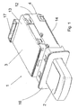
- ein Zündschloßsystem für ein Kraftfahrzeug bestehend aus einem Zündschloß mit einem eingesteckten Schlüssel in perspektivischer Ansicht, wobei der Schlüssel in Ausgangsstellung befindlich ist,
- Fig. 2
- das Zündschloßsystem wie in Fig. 1, wobei der Schlüssel in einer Bewegungsstellung befindlich ist,
- Fig. 3
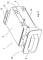
- das Zündschloßsystem wie in Fig. 1, wobei der Schlüssel in einer anderen Bewegungsstellung befindlich ist,
- Fig. 4
- das Zündschloß aus Fig. 1 ohne Schlüssel,
- Fig. 5
- das Zündschloßsystem wie in Fig. 1, wobei jedoch das Gehäuse des Zündschlosses geöffnet ist, und wobei teilweise verdeckt liegende Teile sichtbar sind,
- Fig. 6
- einen vergrößerten Ausschnitt aus Fig. 5 im Bereich der Rastkurven,
- Fig. 7
- eine vergrößerte Detailansicht aus Fig. 5 im Bereich des Rasthebels,
- Fig. 8
- den Boden des geöffneten Gehäuses für das Zündschloß und
- Fig. 9
- ein Kraft-Weg-Diagramm für die Bewegung des Schlüssels im Zündschloß.
- In Fig. 1 ist ein Zündschloßsystem 1 für ein Kraftfahrzeug zu sehen, das aus einem elektronischen Zündschloß 3 und einem elektronischen Schlüssel 2 besteht. Das beispielsweise in der Instrumententafel des Kraftfahrzeugs eingebaute Zündschloß 3 besitzt ein Gehäuse 4. In das Zündschloß 3 ist an einer in Fig. 4 sichtbaren Öffnung 5 im Gehäuse 4 der Schlüssel 2 einsteckbar. Wie weiter in Fig. 5 zu sehen ist, weist das Zündschloß 3 eine in einem Trägerelement 6 befindliche Aufnahme 7 für den Schlüssel 2 auf. Das Trägerelement 6 ist mittels des Schlüssels 2 zwischen einer Ausgangsstellung s1 und hintereinander liegenden Bewegungsstellungen s2 bis s5, die in Fig. 5 mit entsprechenden Pfeilen bezeichnet sind, manuell bewegbar. Hierzu ist das Trägerelement 6 in der Art eines Schiebers linear beweglich ausgestaltet.
- In Fig. 5 ist das Trägerelements 6 in seiner Ausgangsstellung s1 gezeigt, in der der Schlüssel 2 in die Aufnahme 7 einsteckbar sowie aus der Aufnahme 7 entnehmbar ist. Die Bewegungsstellung s2 sowie die Bewegungsstellung s4 für das Trägerelement 6 sind jeweils als Raststellungen ausgebildet. Die beiden Raststellungen werden durch das Zusammenwirken einer in der Art eines Schaltherzens ausgestalteten Rastkurve 8, 9 mit einem Raststift 10 festgelegt. Hierzu greift der Raststift 10 in die Rastkurve 8, 9 ein. Der Raststift 10 ist an einem Schiebeelement 34 angeordnet, das seinerseits zur Bewegungsrichtung des Trägerelements 6 querbeweglich am Trägerelement 6 gelagert ist, wie anhand von Fig. 8 zu erkennen ist. Weiter ist der Raststift 10 über das Schiebeelement 34 mit einer von einer Feder 35 erzeugten elastischen Kraft beaufschlagt. Wie in Fig. 5 zu sehen ist, sind die beiden Rastkurven 8, 9 in Bewegungsrichtung des Trägerelements 6 hintereinander im Zündschloß 3 angeordnet, so daß die Ausgangsstellung s1 und die Bewegungsstellungen s2 bis s5 aufeinander folgen. Selbstverständlich können die beiden Rastkurven 8, 9 auch zueinander versetzt oder in sonstiger geeigneter Weise angeordnet sein.
- Ist der Schlüssel 2 in die Aufnahme 7 eingeführt und wird dieser anschließend mitsamt dem Trägerelement 6 aufgrund manueller Einwirkung des Benutzers auf den Schlüssel 2 von der Ausgangsstellung s1 in eine der Bewegungsstellungen s2 bis s5 gebracht, so wird dabei zwischen dem Schlüssel 2 und dem Zündschloß 3 ein elektronischer Code, und zwar bevorzugt in einer bidirektionalen Kommunikation, ausgetauscht oder übertragen. Nach positiver Auswertung des zwischen dem Schlüssel 2 und dem Zündschloß 3 ausgetauschten elektronischen Codes, d.h. es handelt sich um den berechtigten Schlüssel 2, wird wenigstens eine vom Zündschloß 3 bewirkbare Funktion freigegeben und/oder ausgelöst. Bei dieser freigegebenen und/oder ausgelösten Funktion kann es sich um das Einschalten von Verbrauchern im Kraftfahrzeug, wie um das Radio, die Beleuchtung usw., um das Starten des Kraftfahrzeugs o. dgl. handeln. Der elektronische Code zur Freigabe und/oder Auslösung dieser Funktionen kann bei der Bewegung des Trägerelements 6 zwischen der Ausgangsstellung s1 und einer Bewegungsstellung s2 bis s5, in wenigstens einer der Bewegungsstellungen oder auch falls notwendig in anderen Stellungen, beispielsweise bereits in der Ausgangsstellung s1, zwischen dem Schlüssel 2 und dem Zündschloß 3 ausgetauscht werden. Die Auswertung des elektronischen Codes kann dabei im Zündschloß 3 selbst erfolgen oder falls gewünscht auch in einem separaten Steuergerät. Desweiteren ist der elektronische Code auch von einem sonstigen Identifikationsgeber, wie einer beim Benutzer befindlichen, separaten Chipkarte übertragbar, womit der Schlüssel 2 dann lediglich als Bedienelement im Zündschloß 3 für den Benutzer dient.
- Der nähere Ablauf der Funktionsweise des Zündschloßsystems 1 ist nun anhand der Fig. 5 wie folgt. In der Ausgangsstellung s1 des Trägerelements 6 wird der Schlüssel 2 in die Aufnahme 7 gesteckt und rastet in der Aufnahme 7 ein, was auch in Fig. 1 gezeigt ist. Bei Bewegung des Schlüssels 2, indem der Benutzer auf den Schlüssel 2 drückend einwirkt, bis in die Bewegungsstellung s3 wird die sogenannte "Klemme 15" aktiviert, in der das Zuschalten von Verbrauchern im Kraftfahrzeug ermöglicht ist. Das Trägerelement 6 mitsamt dem Schlüssel 2 bewegt sich dann in die rastende Bewegungsstellung s2 und verbleibt dort. Der Schlüssel 2 in der Bewegungsstellung s2, in der die Zündung des Kraftfahrzeugs eingeschaltet ist, ist auch in Fig. 2 zu sehen. Bei nochmaligem Drücken des Schlüssels 2 durch den Benutzer wird das Trägerelement 6, nachdem eine erhöhte Kraft in der Nähe der Bewegungsstellung s3 überwunden ist, bis in die Bewegungsstellung s5 bewegt, wo der Motor des Kraftfahrzeugs gestartet wird. Das Trägerelement 6 mitsamt dem Schlüssel 2 bleibt danach in der Bewegungsstellung s4 stehen. Die Bewegungsstellung s4, in der sich das Kraftfahrzeug dann im Fahrbetrieb befindet, ist auch in Fig. 3 gezeigt. Bei erneuter Betätigung des Schlüssels 2 durch den Benutzer wird der Motor des Kraftfahrzeugs gestoppt und das Trägerelement 6 mitsamt dem Schlüssel 2 bewegt sich bis in die Ausgangsstellung s1 zurück. Dort kann der Schlüssel 2 dann wiederum aus der Aufnahme 7 abgezogen werden. Schließlich kann, nachdem der Schlüssel 2 durch den Benutzer aus der Bewegungsstellung s2 nur bis zum mechanischen Druckpunkt betätigt und dann losgelassen wird, das Trägerelement 6 mitsamt dem Schlüssel 2 ebenfalls in die Ausgangsstellung s1 zurückgeführt werden, wobei dann kein Motorstart erfolgt.
- Die Bewegungsbahn für den Raststift 10 in den Rastkurven 8, 9 bei diesem Ablauf ist in Fig. 6 eingezeichnet. Die bei diesem Ablauf zur Bewegung des Schlüssels 2 durch den Benutzer notwendige Kraft ist schließlich noch in Fig. 9 dargestellt. Dort ist auch deutlich der Druckpunkt bei der Bewegungsstellung s3 zu sehen. Zum Starten des Kraftfahrzeugs in der Bewegungsstellung s5 dient ein in Fig. 5 näher gezeigtes Betätigungselement 29. Das Betätigungselement 29 besteht aus einer im Gehäuse 4 befestigten Halterung 32, in der ein Druckelement 30 gegen die Kraft einer Feder 31 zum Schalten eines nicht weiter sichtbaren Schaltelements bewegbar ist, wobei das Schaltsignal dieses Schaltelements dann den Startvorgang bewirkt, falls der Code zulässig ist. Das Druckelement 30 wird seinerseits vom Trägerelement 6 in der Bewegungsstellung s5 bewegt.
- Wie bereits erwähnt, ist das Trägerelement 6 durch manuelle Bewegung mittels des Schlüssels 2 bis in die Bewegungsstellung s5 bewegbar, in der das Kraftfahrzeug gestartet wird. Aus der Bewegungsstellung s5 wird das Trägerelement 6 anschließend, und zwar nach Beendigung der manuellen Einwirkung des Benutzers auf den Schlüssel 2, in die der Bewegungsstellung s4 zugeordnete Raststellung selbsttätig zurückgeführt. Zwischen den beiden Rastkurven 8, 9 ist eine in Fig. 6 sichtbare Kontur 11 derart angeordnet, daß der Raststift 10 ausgehend von der Ausgangsstellung s1 entlang der Kontur zunächst in die der ersten Raststellung entsprechende Bewegungsstellung s2 gelenkt wird. Ausgehend von der Ausgangsstellung s1 ist der Motorstart aufgrund der Kontur 11 nur bei zweimaliger Betätigung des Schlüssels 2 durch den Benutzer möglich. Alternativ ist auch eine Ausgestaltung denkbar, welche ein Starten des Motors bereits durch einmaliges Drücken des Schlüssels 2 und Überwindung des Druckpunktes zuläßt. In diesem Fall wird der Teil 11' der Kontur 11 weggelassen, was in Fig. 6 ebenfalls dargestellt ist. Dadurch ist es möglich, ohne in die Bewegungsstellung s2 zu gelangen, das Trägerelement 6 direkt in die Bewegungsstellung s5 zum Starten des Kraftfahrzeugs weiter zu bewegen.
- In weiterer Ausgestaltung besitzt das Zündschloß 3, wie bereits erwähnt und in Fig. 4 gezeigt, ein Gehäuse 4, das im Einzelnen aus einem Grundrahmen 12, einem Deckel 13 und einem Boden 14 besteht. Das Gehäuse 4 weist an seinem Grundrahmen 12 die Öffnung 5 auf. Die Öffnung 5 ist durch das Trägerelement 6 selbst in dessen Ausgangsstellung verschlossen, indem die hohlraumartige Aufnahme 7 im Trägerelement 6 mit der Öffnung 5 korrespondiert. Dadurch ist das Innere des Zündschlosses 3 durch die Wände der Aufnahme 7 im Trägerelement 6 weitgehend abgeschlossen. Zusätzlich kann die Aufnahme 7 noch mittels einer beweglichen und federbelasteten Klappe 15 verschlossen sein, die in Fig. 4 zu sehen ist. Die Klappe 15 wird beim Einstecken des Schlüssels 2 in die Öffnung 5 nach einer Seite wegbewegt und gibt dann die Aufnahme 7 zum vollständigen Einführen des Schlüssels 2 frei. Die Aufnahme 7 für den Schlüssel 2 beziehungsweise die Öffnung 5 ist von einer Blende 16 umrahmt, die auf das Gehäuse 4 aufgerastet wird, um so entsprechende Ausschnitte in der Instrumententafel des Kraftfahrzeugs nach Montage des Zündschlosses 3 zu verdecken. Der elektrische Anschluß des Zündschlosses 3 im Kraftfahrzeug erfolgt über eine Steckerbuchse 17 am Gehäuse 4. Im Gehäuse 4 befindet sich eine in Fig. 5 sichtbare Führung 18 für die lineare Bewegung des als Schieber ausgestalteten Trägerelements 6. Eine Druckfeder 19 dient schließlich zur Erzeugung einer in Richtung auf die Ausgangsstellung s1 wirkenden Rückstellkraft für das Trägerelement 6 bei dessen Bewegung.
- Aus Sicherheitsgründen ist der Schlüssel 2 lediglich in der Ausgangsstellung s1 aus der Aufnahme 7 entnehmbar, indem dieser außerhalb der Ausgangsstellung s1 des Trägerelements 6 in der Aufnahme 7 verrastet ist. Die nähere Ausgestaltung der Verrastung des Schlüssels 2 ist in Fig. 7 dargestellt.
- Am Trägerelement 6 ist zur Verrastung ein Rasthebel 20 verschwenkbar angeordnet. Der Rasthebel 20 ist derart mit einer Druckfeder 21 belastet, daß der Rasthebel 20 in Richtung zur Aufnahme 7 verschwenkt wird. Befindet sich der Schlüssel 2 in der Aufnahme 7, so greift der Rasthebel 20 mittels eines Nockens 22 in eine Ausnehmung 23 am Schlüssel 2 ein, wie anhand von Fig. 7 zu sehen ist. Befindet sich das Trägerelement 6 in der Ausgangsstellung s1, so ist der Rasthebel 20 jedoch gegen die Kraft der Druckfeder 21 in eine Unterbrechung 25 an einer Sperrkontur 33, die sich an der Seitenwand im Gehäuse 4 befindet, derart durch den Schlüssel 2 verschwenkbar, daß der Schlüssel 2 in die Aufnahme 7 einführbar sowie aus dieser entnehmbar ist. Befindet sich jedoch das Trägerelement 6 nicht in der Ausgangsstellung s1, indem dieses mittels des Schlüssels 2 durch manuelle Einwirkung in Richtung der Bewegungsstellungen s2 bis s5 bewegt wird, so liegt der Rasthebel 20 mit einer Fläche 24 am Nocken 22 an der Sperrkontur 33 im Gehäuse 4 an, so daß der Nocken 22 die Ausnehmung 23 am Schlüssel 2 nicht verlassen kann. Der Schlüssel 2 ist dann in der Art einer Abzugssicherung in der Aufnahme 7 festgehalten. Es kann sich anbieten zwei solche Rasthebel 20 beidseitig am Trägerelement 6 anzuordnen, was jedoch in Fig. 7 nicht weiter gezeigt ist.
- In einigen Bewegungsstellungen, und zwar in der Bewegungsstellung s3 und s5 wird eine Funktion des Kraftfahrzeugs freigegeben und/oder ausgelöst, wozu das Trägerelement 6 ein diesen Bewegungsstellungen zugeordnetes elektrisches, elektronisches, optisches, sensorisches o. dgl. Schaltelement betätigt, so daß das Schaltsignal des Schaltelements die jeweilige Funktion kennzeichnet. Bevorzugterweise ist das Schaltelement als Hallsensor 27 ausgebildet und am Trägerelement 6 befindet sich zum Schalten des Hallsensors 27 ein zum Hallsensor 27 korrespondierender Magnet 28, wie in Fig. 8 gezeigt ist. An der Unterseite im Gehäuse 4, und zwar im Boden 14, befindet sich eine insbesondere in Fig. 8 sichtbare, in etwa parallel zur Führung 18 für das Trägerelement 6 angeordnete Leiterplatte 26, die die elektrischen und/oder elektronischen Bauteile aufnimmt. Bei diesen Bauteilen handelt es sich um diejenigen, die zum Betrieb des Zündschlosses 3 notwendig sind. Desweiteren befinden sich die Hallsensoren 27, die Schaltelemente o. dgl. auf der Leiterplatte 26. Die Leiterplatte 26 kann im Gehäuse 4 eingelegt, eingerastet, eingeclipst o. dgl. sein.
- Die Erfindung ist nicht auf das beschriebene und dargestellte Ausführungsbeispiel beschränkt. Sie umfaßt vielmehr auch alle fachmännischen Weiterbildungen im Rahmen der durch die Patentansprüche definierten Erfindung. So kann die Erfindung nicht nur an Zündschloßsystemen für beliebige Fahrzeuge Verwendung finden, sondern auch an sonstigen Schlössern, beispielsweise solchen, die an Arbeitsmaschinen, Immobilien o. dgl. angeordnet sind, eingesetzt werden.
-
- 1:
- Zündschloßsystem
- 2:
- Schlüssel
- 3:
- Zündschloß
- 4:
- Gehäuse
- 5:
- Öffnung (im Gehäuse)
- 6:
- Trägerelement
- 7:
- Aufnahme
- 8,9:
- Rastkurve
- 10:
- Raststift
- 11:
- Kontur
- 11':
- Teil (der Kontur)
- 12:
- Grundrahmen (von Gehäuse)
- 13:
- Deckel (von Gehäuse)
- 14:
- Boden (von Gehäuse)
- 15:
- Klappe
- 16:
- Blende
- 17:
- Steckerbuchse
- 18:
- Führung
- 19:
- Druckfeder (am Trägerelement)
- 20:
- Rasthebel
- 21:
- Druckfeder (am Rasthebel)
- 22:
- Nocken (am Rasthebel)
- 23:
- Ausnehmung (am Schlüssel)
- 24:
- Fläche (an Nocken)
- 25:
- Unterbrechung (in Sperrkontur)
- 26:
- Leiterplatte
- 27:
- Hallsensor
- 28:
- Magnet
- 29:
- Betätigungselement (für Startvorgang des Kraftfahrzeugs)
- 30:
- Druckelement (von Betätigungselement)
- 31:
- Feder (für Druckelement)
- 32:
- Halterung (für Druckelement)
- 33:
- Sperrkontur
- 34:
- Schiebeelement (für Raststift)
- 35:
- Feder (für Raststift)
Claims (9)
- Zündschloßsystem, insbesondere in einem Kraftfahrzeug, mit einem elektronischen Zündschloß (3) sowie mit einem elektronischen Schlüssel (2), wobei das Zündschloß (3) eine in einem Trägerelement (6) befindliche Aufnahme (7) für den Schlüssel (2) aufweist, wobei das Trägerelement (6) in der Art eines Schiebers mittels des Schlüssels (2) zwischen einer Ausgangsstellung (s1) und Bewegungsstellungen (s2, s3, s4, s5) linear bewegbar ist, wobei insbesondere zwischen dem Schlüssel (2) und dem Zündschloß (3) ein elektronischer Code austauschbar ist, und wobei nach positiver Auswertung des Codes wenigstens eine vom Zündschloß (3) bewirkbare Funktion, wie das Einschalten von Verbrauchern im Kraftfahrzeug, das Starten des Kraftfahrzeugs o. dgl., freigegeben ist und/oder ausgelöst wird, dadurch gekennzeichnet, daß eine Bewegungsstellung (s2) sowie eine weitere Bewegungsstellung (s4) für das Trägerelement (6) jeweils als Raststellungen ausgebildet sind, daß die beiden Raststellungen durch das Zusammenwirken einer, insbesondere in der Art eines Schaltherzens ausgestalteten Rastkurve (8, 9) mit einem in die Rastkurve (8, 9) eingreifenden, insbesondere mit einer elastischen Kraft beaufschlagten Raststift (10) festgelegt sind, und daß eine Rückstellkraft, die insbesondere mittels einer Druckfeder (19) erzeugt ist, in Richtung auf die Ausgangsstellung (s1) auf das Trägerelement (6) bei dessen Bewegung in der einen Bewegungsstellung (s2) sowie der weiteren Bewegungsstellung (s4) einwirkt.
- Zündschloßsystem nach Anspruch 1, dadurch gekennzeichnet, daß die beiden Rastkurven (8,9) in Bewegungsrichtung des Trägerelements (6) hintereinander angeordnet sind.
- Zündschloßsystem nach Anspruch 1 oder 2, dadurch gekennzeichnet, daß das Trägerelement (6) durch Bewegung bis in noch eine weitere Bewegungsstellung (s5), in der das Kraftfahrzeug gestartet wird, insbesondere manuell bewegbar ist, und daß vorzugsweise das Trägerelement (6) aus der noch weiteren Bewegungsstellung (s5) in die der weiteren Bewegunsstellung (s4) zugeordnete Raststellung, insbesondere nach Beendigung der manuellen Einwirkung selbsttätig, zurückgeführt wird.
- Zündschloßsystem nach Anspruch 1, 2 oder 3, dadurch gekennzeichnet, daß zwischen den beiden Rastkurven (8, 9) eine Kontur (11) derart angeordnet ist, daß der Raststift (10) ausgehend von der Ausgangsstellung (s1) entlang der Kontur (11) zunächst in die der einen Bewegungsstellung (s2) entsprechende Raststellung gelenkt wird.
- Zündschloßsystem nach einem der Ansprüche 1 bis 4, dadurch gekennzeichnet, daß das Zündschloß (3) ein Gehäuse (4) mit einer Öffnung (5) aufweist, daß vorzugsweise die Öffnung (5) durch das (6) in dessen Ausgangsstellung (s1) verschlossen ist, indem die beispielsweise hohlraumartige Aufnahme (7) im Trägerelement (6) mit der Öffnung (5) korrespondiert, daß weiter vorzugsweise eine vom Schlüssel (2) bewegliche Klappe (15), die insbesondere federbelastet ausgestaltet ist, die Aufnahme (7) verschließt, und daß noch weiter vorzugsweise im Gehäuse (4) eine Führung (18) für die Bewegung des Trägerelements (6) befindlich ist.
- Zündschloßsystem nach einem der Ansprüche 1 bis 5, dadurch gekennzeichnet, daß am Trägerelement (6) ein, insbesondere mit einer Druckfeder (21) belasteter, verschwenkbarer Rasthebel (20) angeordnet ist, gegebenenfalls zwei Rasthebel (20) beidseitig angeordnet sind, wobei vorzugsweise der Rasthebel (20) mittels eines Nockens (22) bei in der Aufnahme (7) befindlichem Schlüssel (2) in eine Ausnehmung (23) am Schlüssel (2) eingreift, sowie insbesondere mittels einer Sperrkontur (33) im Gehäuse (4) bei nicht in der Ausgangsstellung (s1) befindlichem Trägerelement (6) in der Ausnehmung (23) in der Art einer Abzugssicherung für den Schlüssel (2) festgehalten ist, und wobei weiter vorzugsweise der Rasthebel (20) in der Ausgangsstellung (s1) des Trägerelements (6) gegen die Kraft der Druckfeder (21) in eine Unterbrechung (25) an der Sperrkontur (33) derart verschwenkbar ist, daß der Schlüssel (2) in die Aufnahme (7) einführbar sowie entnehmbar ist.
- Zündschloßsystem nach einem der Ansprüche 1 bis 6, dadurch gekennzeichnet, daß das Trägerelement (6) in wenigstens einer Bewegungsstellung (s3, s5) ein elektrisches, elektronisches, optisches, sensorisches o. dgl. Schaltelement betätigt, dessen Schaltsignal insbesondere die vom Zündschloß (3) bewirkbare Funktion kennzeichnet, daß vorzugsweise das Schaltelement als Hallsensor (27) ausgebildet ist, und daß weiter vorzugsweise am Trägerelement (6) ein zum Hallsensor (27) korrespondierender Magnet (28) angeordnet ist.
- Zündschloßsystem nach einem der Ansprüche 1 bis 7, dadurch gekennzeichnet, daß im Gehäuse (4) eine Leiterplatte (26) zur Aufnahme der elektrischen und/oder elektronischen Bauteile, wie des Schaltelements, des Hallsensors (27) o. dgl., insbesondere in etwa parallel zur Führung (18) für das Trägerelement (6), angeordnet ist, und daß vorzugsweise die Leiterplatte (26) im Gehäuse (4) eingelegt, eingerastet, eingeclipst o. dgl. ist.
- Zündschloßsystem nach einem der Ansprüche 1 bis 8, dadurch gekennzeichnet, daß die Aufnahme (7) durch eine Blende (16) umrahmt ist, wobei insbesondere die Blende (16) auf das Gehäuse (4) aufgerastet ist.
Applications Claiming Priority (2)
| Application Number | Priority Date | Filing Date | Title |
|---|---|---|---|
| DE10253520 | 2002-11-16 | ||
| DE10253520 | 2002-11-16 |
Publications (2)
| Publication Number | Publication Date |
|---|---|
| EP1419944A1 EP1419944A1 (de) | 2004-05-19 |
| EP1419944B1 true EP1419944B1 (de) | 2006-01-18 |
Family
ID=32115555
Family Applications (1)
| Application Number | Title | Priority Date | Filing Date |
|---|---|---|---|
| EP03026207A Expired - Lifetime EP1419944B1 (de) | 2002-11-16 | 2003-11-14 | Zündschlosssystem für ein Kraftfahrzeug |
Country Status (3)
| Country | Link |
|---|---|
| EP (1) | EP1419944B1 (de) |
| AT (1) | ATE316024T1 (de) |
| DE (2) | DE10353195A1 (de) |
Cited By (1)
| Publication number | Priority date | Publication date | Assignee | Title |
|---|---|---|---|---|
| US7334441B1 (en) | 2007-01-16 | 2008-02-26 | Lear Corporation | Electronic vehicle key and housing assembly |
Families Citing this family (14)
| Publication number | Priority date | Publication date | Assignee | Title |
|---|---|---|---|---|
| DE102005003858A1 (de) * | 2005-01-27 | 2006-08-03 | Leopold Kostal Gmbh & Co. Kg | Zündschloßsystem für ein Kraftfahrzeug |
| DE102005011782A1 (de) | 2005-03-11 | 2006-09-14 | Marquardt Gmbh | Zündschlosssystem für ein Kraftfahrzeug |
| DE102005038437A1 (de) * | 2005-08-12 | 2007-02-15 | Huf Hülsbeck & Fürst GmbH & Co KG | Zündvorrichtung für einen Motor, insbesondere in einem Kraftfahrzeug |
| DE102005043232A1 (de) | 2005-09-09 | 2007-03-15 | Bayerische Motoren Werke Ag | Vorrichtung zum Starten des Motors eines Kraftfahrzeugs |
| DE102005062162A1 (de) * | 2005-12-22 | 2007-06-28 | Huf Hülsbeck & Fürst Gmbh & Co. Kg | Zünd-Anlaß-Schaltereinrichtung |
| DE102006008625A1 (de) * | 2006-02-24 | 2007-08-30 | Marquardt Gmbh | Zündschloss mit verbesserter Manipulationssicherheit |
| DE102006008624A1 (de) * | 2006-02-24 | 2007-08-30 | Marquardt Gmbh | Sperrvorrichtung für ein bewegliches Element |
| GB2474391B (en) * | 2006-04-07 | 2011-06-01 | Aston Martin Lagonda Ltd | Docking station for an electronic key fob |
| US7617708B2 (en) | 2006-07-28 | 2009-11-17 | Volkswagen Ag | Ignition lock for a motor vehicle and method of operating an ignition lock system |
| DE102007022248A1 (de) * | 2007-05-09 | 2008-11-13 | Huf Hülsbeck & Fürst Gmbh & Co. Kg | Vorrichtung zur Aufnahme eines elektronischen Schlüssels |
| DE102007043039B4 (de) | 2007-09-11 | 2019-12-19 | Huf Hülsbeck & Fürst Gmbh & Co. Kg | Vorrichtung zur Aufnahme eines elektronischen Schlüssels |
| DE102007054473A1 (de) * | 2007-11-13 | 2009-05-14 | Huf Hülsbeck & Fürst Gmbh & Co. Kg | Vorrichtung zur Aufnahme eines elektronischen Schlüssels |
| DE102009039142A1 (de) * | 2009-08-27 | 2011-03-03 | GM Global Technology Operations, Inc., Detroit | Bedienteil für ein Kraftfahrzeug |
| WO2021127753A1 (en) * | 2019-12-26 | 2021-07-01 | U-Shin Do Brasil Sistemas Automotivos Ltda. | Vehicle ignition control unit |
Family Cites Families (2)
| Publication number | Priority date | Publication date | Assignee | Title |
|---|---|---|---|---|
| DE19939733C2 (de) * | 1999-08-21 | 2001-10-11 | Huf Huelsbeck & Fuerst Gmbh | Vorrichtung zum Starten eines Fahrzeugmotors mittels eines elektronischen Schlüssels |
| DE10233061A1 (de) * | 2001-07-25 | 2003-02-13 | Marquardt Gmbh | Zündschloßsystem für ein Kraftfahrzeug |
-
2003
- 2003-11-13 DE DE10353195A patent/DE10353195A1/de not_active Withdrawn
- 2003-11-14 DE DE50302224T patent/DE50302224D1/de not_active Expired - Lifetime
- 2003-11-14 EP EP03026207A patent/EP1419944B1/de not_active Expired - Lifetime
- 2003-11-14 AT AT03026207T patent/ATE316024T1/de not_active IP Right Cessation
Cited By (1)
| Publication number | Priority date | Publication date | Assignee | Title |
|---|---|---|---|---|
| US7334441B1 (en) | 2007-01-16 | 2008-02-26 | Lear Corporation | Electronic vehicle key and housing assembly |
Also Published As
| Publication number | Publication date |
|---|---|
| ATE316024T1 (de) | 2006-02-15 |
| DE10353195A1 (de) | 2004-08-12 |
| DE50302224D1 (de) | 2006-04-06 |
| EP1419944A1 (de) | 2004-05-19 |
Similar Documents
| Publication | Publication Date | Title |
|---|---|---|
| EP1419944B1 (de) | Zündschlosssystem für ein Kraftfahrzeug | |
| EP1279576B1 (de) | Zündschlosssystem für ein Kraftfahrzeug | |
| EP1737713A1 (de) | Vorrichtung zum starten eines fahrzeugmotors mittels eines elektronischen schlüssels und ein dazu zu verwendender schlüssel | |
| EP3621855B1 (de) | Verriegelungseinrichtung, insbesondere für ein kraftfahrzeug | |
| EP1135284B1 (de) | Schliessystem, insbesondere für kraftfahrzeuge | |
| EP1177942B1 (de) | Rückstelleinrichtung für einen Schalter eines Kraftfahrzeuges | |
| EP1462325B1 (de) | Zündschlosssystem für ein Kraftfahrzeug | |
| DE19756341B4 (de) | Schließsystem, insbesondere für Kraftfahrzeuge | |
| WO1999006261A2 (de) | Lenkradverriegelung an einem kraftfahrzeug | |
| EP1700760B1 (de) | Zündschlosssystem für ein Kraftfahrzeug | |
| EP1607289B1 (de) | Zündschloss für ein Kraftfahrzeug | |
| EP1434706B1 (de) | Zündschloss | |
| DE3516732C1 (de) | Kombinierte Zentralverriegelungs- und Sicherungsanlage für Verschlüsse an einem Kraftfahrzeug | |
| DE10106123B4 (de) | Elektrisches/elektronisches Schaltsystem für Kraftfahrzeuge | |
| DE102005037440A1 (de) | Zündschloß für ein Kraftfahrzeug | |
| DE102004024253A1 (de) | Zündschloß für ein Kraftfahrzeug | |
| EP1776262B1 (de) | Zündschloss für ein kraftfahrzeug | |
| EP1048527B2 (de) | Für ein Kraftfahrzeug bestimmtes Einbaugerät | |
| DE10021810C2 (de) | Ausbausicherung für ein in ein Kraftfahrzeug eingebautes elektrisches Gerät | |
| DE19809062A1 (de) | Verfahren zum Steuern eines fremdkraftbetätigt zu öffnenden Daches eines Fahrzeuges mit einer Betätigungseinrichtung | |
| EP2231970B1 (de) | Aktuator für einen elektromechanischen drehschliesszylinder und einen elektromechanischen drehschliesszylinder mit einem solchen aktuator | |
| EP2036790B1 (de) | Zündschloss für ein Kraftfahrzeug | |
| DE102005028097A1 (de) | Zündschloß für ein Kraftfahrzeug | |
| DE10143804A1 (de) | Zündschloß für ein Kraftfahrzeug | |
| DE102008047107A1 (de) | Zündschloß für ein Kraftfahrzeug |
Legal Events
| Date | Code | Title | Description |
|---|---|---|---|
| PUAI | Public reference made under article 153(3) epc to a published international application that has entered the european phase |
Free format text: ORIGINAL CODE: 0009012 |
|
| AK | Designated contracting states |
Kind code of ref document: A1 Designated state(s): AT BE BG CH CY CZ DE DK EE ES FI FR GB GR HU IE IT LI LU MC NL PT RO SE SI SK TR |
|
| AX | Request for extension of the european patent |
Extension state: AL LT LV MK |
|
| 17P | Request for examination filed |
Effective date: 20040910 |
|
| 17Q | First examination report despatched |
Effective date: 20041018 |
|
| AKX | Designation fees paid |
Designated state(s): AT BE BG CH CY CZ DE DK EE ES FI FR GB GR HU IE IT LI LU MC NL PT RO SE SI SK TR |
|
| GRAP | Despatch of communication of intention to grant a patent |
Free format text: ORIGINAL CODE: EPIDOSNIGR1 |
|
| GRAS | Grant fee paid |
Free format text: ORIGINAL CODE: EPIDOSNIGR3 |
|
| GRAA | (expected) grant |
Free format text: ORIGINAL CODE: 0009210 |
|
| AK | Designated contracting states |
Kind code of ref document: B1 Designated state(s): AT BE BG CH CY CZ DE DK EE ES FI FR GB GR HU IE IT LI LU MC NL PT RO SE SI SK TR |
|
| PG25 | Lapsed in a contracting state [announced via postgrant information from national office to epo] |
Ref country code: IT Free format text: LAPSE BECAUSE OF FAILURE TO SUBMIT A TRANSLATION OF THE DESCRIPTION OR TO PAY THE FEE WITHIN THE PRESCRIBED TIME-LIMIT;WARNING: LAPSES OF ITALIAN PATENTS WITH EFFECTIVE DATE BEFORE 2007 MAY HAVE OCCURRED AT ANY TIME BEFORE 2007. THE CORRECT EFFECTIVE DATE MAY BE DIFFERENT FROM THE ONE RECORDED. Effective date: 20060118 Ref country code: SI Free format text: LAPSE BECAUSE OF FAILURE TO SUBMIT A TRANSLATION OF THE DESCRIPTION OR TO PAY THE FEE WITHIN THE PRESCRIBED TIME-LIMIT Effective date: 20060118 Ref country code: SK Free format text: LAPSE BECAUSE OF FAILURE TO SUBMIT A TRANSLATION OF THE DESCRIPTION OR TO PAY THE FEE WITHIN THE PRESCRIBED TIME-LIMIT Effective date: 20060118 Ref country code: RO Free format text: LAPSE BECAUSE OF FAILURE TO SUBMIT A TRANSLATION OF THE DESCRIPTION OR TO PAY THE FEE WITHIN THE PRESCRIBED TIME-LIMIT Effective date: 20060118 Ref country code: FI Free format text: LAPSE BECAUSE OF FAILURE TO SUBMIT A TRANSLATION OF THE DESCRIPTION OR TO PAY THE FEE WITHIN THE PRESCRIBED TIME-LIMIT Effective date: 20060118 Ref country code: GB Free format text: LAPSE BECAUSE OF FAILURE TO SUBMIT A TRANSLATION OF THE DESCRIPTION OR TO PAY THE FEE WITHIN THE PRESCRIBED TIME-LIMIT Effective date: 20060118 Ref country code: IE Free format text: LAPSE BECAUSE OF FAILURE TO SUBMIT A TRANSLATION OF THE DESCRIPTION OR TO PAY THE FEE WITHIN THE PRESCRIBED TIME-LIMIT Effective date: 20060118 Ref country code: NL Free format text: LAPSE BECAUSE OF FAILURE TO SUBMIT A TRANSLATION OF THE DESCRIPTION OR TO PAY THE FEE WITHIN THE PRESCRIBED TIME-LIMIT Effective date: 20060118 |
|
| REG | Reference to a national code |
Ref country code: GB Ref legal event code: FG4D Free format text: NOT ENGLISH |
|
| REG | Reference to a national code |
Ref country code: CH Ref legal event code: EP |
|
| REG | Reference to a national code |
Ref country code: IE Ref legal event code: FG4D Free format text: LANGUAGE OF EP DOCUMENT: GERMAN |
|
| REF | Corresponds to: |
Ref document number: 50302224 Country of ref document: DE Date of ref document: 20060406 Kind code of ref document: P |
|
| PG25 | Lapsed in a contracting state [announced via postgrant information from national office to epo] |
Ref country code: SE Free format text: LAPSE BECAUSE OF FAILURE TO SUBMIT A TRANSLATION OF THE DESCRIPTION OR TO PAY THE FEE WITHIN THE PRESCRIBED TIME-LIMIT Effective date: 20060418 Ref country code: DK Free format text: LAPSE BECAUSE OF FAILURE TO SUBMIT A TRANSLATION OF THE DESCRIPTION OR TO PAY THE FEE WITHIN THE PRESCRIBED TIME-LIMIT Effective date: 20060418 Ref country code: BG Free format text: LAPSE BECAUSE OF FAILURE TO SUBMIT A TRANSLATION OF THE DESCRIPTION OR TO PAY THE FEE WITHIN THE PRESCRIBED TIME-LIMIT Effective date: 20060418 |
|
| PG25 | Lapsed in a contracting state [announced via postgrant information from national office to epo] |
Ref country code: ES Free format text: LAPSE BECAUSE OF FAILURE TO SUBMIT A TRANSLATION OF THE DESCRIPTION OR TO PAY THE FEE WITHIN THE PRESCRIBED TIME-LIMIT Effective date: 20060429 |
|
| PG25 | Lapsed in a contracting state [announced via postgrant information from national office to epo] |
Ref country code: PT Free format text: LAPSE BECAUSE OF FAILURE TO SUBMIT A TRANSLATION OF THE DESCRIPTION OR TO PAY THE FEE WITHIN THE PRESCRIBED TIME-LIMIT Effective date: 20060619 |
|
| NLV1 | Nl: lapsed or annulled due to failure to fulfill the requirements of art. 29p and 29m of the patents act | ||
| GBV | Gb: ep patent (uk) treated as always having been void in accordance with gb section 77(7)/1977 [no translation filed] |
Effective date: 20060118 |
|
| ET | Fr: translation filed | ||
| REG | Reference to a national code |
Ref country code: IE Ref legal event code: FD4D |
|
| PLBE | No opposition filed within time limit |
Free format text: ORIGINAL CODE: 0009261 |
|
| STAA | Information on the status of an ep patent application or granted ep patent |
Free format text: STATUS: NO OPPOSITION FILED WITHIN TIME LIMIT |
|
| PG25 | Lapsed in a contracting state [announced via postgrant information from national office to epo] |
Ref country code: MC Free format text: LAPSE BECAUSE OF NON-PAYMENT OF DUE FEES Effective date: 20061130 Ref country code: BE Free format text: LAPSE BECAUSE OF NON-PAYMENT OF DUE FEES Effective date: 20061130 |
|
| 26N | No opposition filed |
Effective date: 20061019 |
|
| BERE | Be: lapsed |
Owner name: MARQUARDT G.M.B.H. Effective date: 20061130 Owner name: VOLKSWAGEN A.G. Effective date: 20061130 |
|
| PG25 | Lapsed in a contracting state [announced via postgrant information from national office to epo] |
Ref country code: AT Free format text: LAPSE BECAUSE OF NON-PAYMENT OF DUE FEES Effective date: 20061114 |
|
| PG25 | Lapsed in a contracting state [announced via postgrant information from national office to epo] |
Ref country code: CZ Free format text: LAPSE BECAUSE OF FAILURE TO SUBMIT A TRANSLATION OF THE DESCRIPTION OR TO PAY THE FEE WITHIN THE PRESCRIBED TIME-LIMIT Effective date: 20060118 Ref country code: GR Free format text: LAPSE BECAUSE OF FAILURE TO SUBMIT A TRANSLATION OF THE DESCRIPTION OR TO PAY THE FEE WITHIN THE PRESCRIBED TIME-LIMIT Effective date: 20060419 |
|
| PG25 | Lapsed in a contracting state [announced via postgrant information from national office to epo] |
Ref country code: EE Free format text: LAPSE BECAUSE OF FAILURE TO SUBMIT A TRANSLATION OF THE DESCRIPTION OR TO PAY THE FEE WITHIN THE PRESCRIBED TIME-LIMIT Effective date: 20060118 |
|
| PG25 | Lapsed in a contracting state [announced via postgrant information from national office to epo] |
Ref country code: LI Free format text: LAPSE BECAUSE OF NON-PAYMENT OF DUE FEES Effective date: 20071130 Ref country code: CH Free format text: LAPSE BECAUSE OF NON-PAYMENT OF DUE FEES Effective date: 20071130 Ref country code: TR Free format text: LAPSE BECAUSE OF FAILURE TO SUBMIT A TRANSLATION OF THE DESCRIPTION OR TO PAY THE FEE WITHIN THE PRESCRIBED TIME-LIMIT Effective date: 20060118 Ref country code: HU Free format text: LAPSE BECAUSE OF FAILURE TO SUBMIT A TRANSLATION OF THE DESCRIPTION OR TO PAY THE FEE WITHIN THE PRESCRIBED TIME-LIMIT Effective date: 20060719 Ref country code: LU Free format text: LAPSE BECAUSE OF NON-PAYMENT OF DUE FEES Effective date: 20061114 |
|
| REG | Reference to a national code |
Ref country code: CH Ref legal event code: PL |
|
| PG25 | Lapsed in a contracting state [announced via postgrant information from national office to epo] |
Ref country code: CY Free format text: LAPSE BECAUSE OF FAILURE TO SUBMIT A TRANSLATION OF THE DESCRIPTION OR TO PAY THE FEE WITHIN THE PRESCRIBED TIME-LIMIT Effective date: 20060118 |
|
| REG | Reference to a national code |
Ref country code: FR Ref legal event code: PLFP Year of fee payment: 13 |
|
| REG | Reference to a national code |
Ref country code: FR Ref legal event code: PLFP Year of fee payment: 14 |
|
| REG | Reference to a national code |
Ref country code: FR Ref legal event code: PLFP Year of fee payment: 15 |
|
| PGFP | Annual fee paid to national office [announced via postgrant information from national office to epo] |
Ref country code: FR Payment date: 20171121 Year of fee payment: 15 Ref country code: DE Payment date: 20171214 Year of fee payment: 15 |
|
| REG | Reference to a national code |
Ref country code: DE Ref legal event code: R119 Ref document number: 50302224 Country of ref document: DE |
|
| PG25 | Lapsed in a contracting state [announced via postgrant information from national office to epo] |
Ref country code: FR Free format text: LAPSE BECAUSE OF NON-PAYMENT OF DUE FEES Effective date: 20181130 Ref country code: DE Free format text: LAPSE BECAUSE OF NON-PAYMENT OF DUE FEES Effective date: 20190601 |