EP2231302B1 - Air filter arrangements; assemblies; and, methods - Google Patents
Air filter arrangements; assemblies; and, methods Download PDFInfo
- Publication number
- EP2231302B1 EP2231302B1 EP08848734.3A EP08848734A EP2231302B1 EP 2231302 B1 EP2231302 B1 EP 2231302B1 EP 08848734 A EP08848734 A EP 08848734A EP 2231302 B1 EP2231302 B1 EP 2231302B1
- Authority
- EP
- European Patent Office
- Prior art keywords
- filter cartridge
- air
- housing
- media pack
- arrangement
- Prior art date
- Legal status (The legal status is an assumption and is not a legal conclusion. Google has not performed a legal analysis and makes no representation as to the accuracy of the status listed.)
- Active
Links
- 238000000034 method Methods 0.000 title claims description 29
- 230000000712 assembly Effects 0.000 title description 5
- 238000000429 assembly Methods 0.000 title description 5
- 230000002093 peripheral effect Effects 0.000 claims description 20
- 239000000463 material Substances 0.000 claims description 18
- 229920002635 polyurethane Polymers 0.000 claims description 13
- 239000004814 polyurethane Substances 0.000 claims description 13
- 238000004891 communication Methods 0.000 claims description 6
- 229920003043 Cellulose fiber Polymers 0.000 claims description 4
- 229920003023 plastic Polymers 0.000 claims description 4
- 239000004033 plastic Substances 0.000 claims description 4
- 239000002184 metal Substances 0.000 claims description 3
- 229910052751 metal Inorganic materials 0.000 claims description 3
- 239000011324 bead Substances 0.000 description 34
- 238000010276 construction Methods 0.000 description 15
- 239000010410 layer Substances 0.000 description 15
- 239000000565 sealant Substances 0.000 description 15
- 230000008569 process Effects 0.000 description 12
- 238000007789 sealing Methods 0.000 description 11
- 239000000853 adhesive Substances 0.000 description 10
- 230000001070 adhesive effect Effects 0.000 description 10
- 239000000428 dust Substances 0.000 description 10
- 238000012512 characterization method Methods 0.000 description 7
- 239000000356 contaminant Substances 0.000 description 6
- 238000001914 filtration Methods 0.000 description 6
- 239000012530 fluid Substances 0.000 description 5
- 238000009434 installation Methods 0.000 description 5
- XLYOFNOQVPJJNP-UHFFFAOYSA-N water Substances O XLYOFNOQVPJJNP-UHFFFAOYSA-N 0.000 description 5
- 230000008901 benefit Effects 0.000 description 4
- 230000006835 compression Effects 0.000 description 4
- 238000007906 compression Methods 0.000 description 4
- 238000004519 manufacturing process Methods 0.000 description 4
- 230000004048 modification Effects 0.000 description 4
- 238000012986 modification Methods 0.000 description 4
- 239000011347 resin Substances 0.000 description 4
- 229920005989 resin Polymers 0.000 description 4
- 238000002485 combustion reaction Methods 0.000 description 3
- 239000002657 fibrous material Substances 0.000 description 3
- 238000011144 upstream manufacturing Methods 0.000 description 3
- 230000015572 biosynthetic process Effects 0.000 description 2
- 230000008859 change Effects 0.000 description 2
- 235000019589 hardness Nutrition 0.000 description 2
- 239000012943 hotmelt Substances 0.000 description 2
- 238000007689 inspection Methods 0.000 description 2
- 238000012552 review Methods 0.000 description 2
- 230000007704 transition Effects 0.000 description 2
- 238000003466 welding Methods 0.000 description 2
- 238000004804 winding Methods 0.000 description 2
- 239000004831 Hot glue Substances 0.000 description 1
- 229920005830 Polyurethane Foam Polymers 0.000 description 1
- 238000013459 approach Methods 0.000 description 1
- 238000005452 bending Methods 0.000 description 1
- 230000003247 decreasing effect Effects 0.000 description 1
- 239000000835 fiber Substances 0.000 description 1
- 230000009477 glass transition Effects 0.000 description 1
- 230000005484 gravity Effects 0.000 description 1
- 238000010438 heat treatment Methods 0.000 description 1
- 230000002401 inhibitory effect Effects 0.000 description 1
- 230000013011 mating Effects 0.000 description 1
- 239000012092 media component Substances 0.000 description 1
- 239000002991 molded plastic Substances 0.000 description 1
- 238000000465 moulding Methods 0.000 description 1
- 229920000642 polymer Polymers 0.000 description 1
- 239000011496 polyurethane foam Substances 0.000 description 1
- 238000004382 potting Methods 0.000 description 1
- 238000010248 power generation Methods 0.000 description 1
- 230000002829 reductive effect Effects 0.000 description 1
- 238000009419 refurbishment Methods 0.000 description 1
- 230000000717 retained effect Effects 0.000 description 1
- 239000012812 sealant material Substances 0.000 description 1
- 239000003566 sealing material Substances 0.000 description 1
- 239000002356 single layer Substances 0.000 description 1
- 238000005728 strengthening Methods 0.000 description 1
- 239000012209 synthetic fiber Substances 0.000 description 1
- 229920002994 synthetic fiber Polymers 0.000 description 1
Images


Classifications
-
- B—PERFORMING OPERATIONS; TRANSPORTING
- B01—PHYSICAL OR CHEMICAL PROCESSES OR APPARATUS IN GENERAL
- B01D—SEPARATION
- B01D46/00—Filters or filtering processes specially modified for separating dispersed particles from gases or vapours
- B01D46/52—Particle separators, e.g. dust precipitators, using filters embodying folded corrugated or wound sheet material
- B01D46/521—Particle separators, e.g. dust precipitators, using filters embodying folded corrugated or wound sheet material using folded, pleated material
- B01D46/525—Particle separators, e.g. dust precipitators, using filters embodying folded corrugated or wound sheet material using folded, pleated material which comprises flutes
- B01D46/526—Particle separators, e.g. dust precipitators, using filters embodying folded corrugated or wound sheet material using folded, pleated material which comprises flutes in stacked arrangement
-
- B—PERFORMING OPERATIONS; TRANSPORTING
- B01—PHYSICAL OR CHEMICAL PROCESSES OR APPARATUS IN GENERAL
- B01D—SEPARATION
- B01D46/00—Filters or filtering processes specially modified for separating dispersed particles from gases or vapours
- B01D46/0002—Casings; Housings; Frame constructions
- B01D46/0004—Details of removable closures, lids, caps or filter heads
-
- B—PERFORMING OPERATIONS; TRANSPORTING
- B01—PHYSICAL OR CHEMICAL PROCESSES OR APPARATUS IN GENERAL
- B01D—SEPARATION
- B01D46/00—Filters or filtering processes specially modified for separating dispersed particles from gases or vapours
- B01D46/0002—Casings; Housings; Frame constructions
- B01D46/0005—Mounting of filtering elements within casings, housings or frames
-
- B—PERFORMING OPERATIONS; TRANSPORTING
- B01—PHYSICAL OR CHEMICAL PROCESSES OR APPARATUS IN GENERAL
- B01D—SEPARATION
- B01D46/00—Filters or filtering processes specially modified for separating dispersed particles from gases or vapours
- B01D46/10—Particle separators, e.g. dust precipitators, using filter plates, sheets or pads having plane surfaces
-
- B—PERFORMING OPERATIONS; TRANSPORTING
- B01—PHYSICAL OR CHEMICAL PROCESSES OR APPARATUS IN GENERAL
- B01D—SEPARATION
- B01D46/00—Filters or filtering processes specially modified for separating dispersed particles from gases or vapours
- B01D46/24—Particle separators, e.g. dust precipitators, using rigid hollow filter bodies
- B01D46/2403—Particle separators, e.g. dust precipitators, using rigid hollow filter bodies characterised by the physical shape or structure of the filtering element
- B01D46/2411—Filter cartridges
- B01D46/2414—End caps including additional functions or special forms
-
- B—PERFORMING OPERATIONS; TRANSPORTING
- B01—PHYSICAL OR CHEMICAL PROCESSES OR APPARATUS IN GENERAL
- B01D—SEPARATION
- B01D46/00—Filters or filtering processes specially modified for separating dispersed particles from gases or vapours
- B01D46/56—Filters or filtering processes specially modified for separating dispersed particles from gases or vapours with multiple filtering elements, characterised by their mutual disposition
- B01D46/62—Filters or filtering processes specially modified for separating dispersed particles from gases or vapours with multiple filtering elements, characterised by their mutual disposition connected in series
-
- B—PERFORMING OPERATIONS; TRANSPORTING
- B01—PHYSICAL OR CHEMICAL PROCESSES OR APPARATUS IN GENERAL
- B01D—SEPARATION
- B01D2271/00—Sealings for filters specially adapted for separating dispersed particles from gases or vapours
- B01D2271/02—Gaskets, sealings
- B01D2271/027—Radial sealings
-
- Y—GENERAL TAGGING OF NEW TECHNOLOGICAL DEVELOPMENTS; GENERAL TAGGING OF CROSS-SECTIONAL TECHNOLOGIES SPANNING OVER SEVERAL SECTIONS OF THE IPC; TECHNICAL SUBJECTS COVERED BY FORMER USPC CROSS-REFERENCE ART COLLECTIONS [XRACs] AND DIGESTS
- Y10—TECHNICAL SUBJECTS COVERED BY FORMER USPC
- Y10T—TECHNICAL SUBJECTS COVERED BY FORMER US CLASSIFICATION
- Y10T156/00—Adhesive bonding and miscellaneous chemical manufacture
- Y10T156/10—Methods of surface bonding and/or assembly therefor
Definitions
- the present disclosure relates to filter arrangements for use in filtering air.
- the disclosure particularly relates to filter arrangement with media packs that use z-filter media as characterized herein. More specifically, the disclosure relates to such media packs and their inclusion in serviceable air filter cartridge arrangements, typically for use in air cleaners (air cleaner assemblies). Air cleaner arrangements and methods of assembly and use are also described.
- Air streams can carry contaminant material therein.
- air flow streams to engines for example combustion air
- gas streams to gas turbine systems and air streams to various combustion furnaces carry particulate contaminant therein that should be filtered. It is preferred for such systems, that selected contaminant material be removed from (or have its level reduced in) the air.
- a variety of air filter arrangements have been developed for contaminant collection. Improvements are sought.
- air cleaner assemblies (arrangements) and components therefor are described.
- a first air filter cartridge usable as a service component in the air cleaner assembly.
- the first air filter cartridge generally comprises a media pack positioned in a filter cartridge housing; typically the media pack is non-removably positioned in the filter cartridge housing.
- the media pack is typically a z-filter media pack and has an inlet flow face and an opposite outlet flow face.
- the media pack is positioned in a shell or shell member of the filter cartridge housing with the outlet flow face directed toward a closed end of the shell; the shell having first and second side sections and a closed end section.
- the example shells depicted have either a d/b-shape or a u-shape. In either case, the shell typically has open sides, closed in the filter cartridge housing by a opposite first and second end members.
- the first end member is positioned over a first side of the media pack and shell.
- the first end member generally: includes a air flow outlet arrangement therethrough, in flow communication with a clean air volume defined between the closed end of the shell and the outlet flow face of the media pack; and, closes a first side of the media pack.
- the second end member is positioned opposite the first end member, and closes a second side of the shell and the media pack, opposite the first side.
- the second end member is typically closed to passage of air therethrough.
- the resulting filter cartridge can be provided with a housing seal arrangement around the air flow outlet arrangement.
- the housing seal arrangement comprises a radial seal arrangement molded-in-place as part of the first embodiment; a specific example being an inwardly directed radial seal arrangement, although alternatives are possible.
- the second member includes a peripheral housing seal member thereon, oriented to engage, and seal to, an interior side wall of an air cleaner housing.
- An air cleaner assembly is configured to operably receive the filter cartridge therein.
- An example air cleaner housing includes an inlet arrangement (or inlet), a housing body, and an air flow outlet arrangement (or outlet) oriented through the housing in a direction of air flow generally orthogonal to an air flow direction into the inlet end.
- the housing can include a flange around the outlet arrangement through the housing. The flange can be positioned for sealing engagement with a housing seal arrangement on the filter cartridge, oriented in association with an air flow outlet of the filter cartridge.
- An optional secondary or safety filter cartridge can be positioned sealed to the housing, and projecting into the clean air volume of the first filter cartridge.
- the shell closed end section includes a drain aperture arrangement therein, to allow for drainage of water from a downstream end of the filter cartridge.
- filter media is positioned over the aperture arrangement, since the aperture arrangement is through the shell at the clean air side of the filter cartridge. Thus, the filter media closes the shell at this location.
- Fluted filter media can be used to provide fluid filter constructions in a variety of manners.
- One well known manner is characterized herein as a z-filter construction.
- the term "z-filter construction" as used herein, is meant to refer to a filter construction in which individual ones of corrugated, folded or otherwise formed filter flutes are used to define sets of longitudinal, typically parallel, inlet and outlet filter flutes for fluid flow through the media; the fluid flowing along the length of the flutes between opposite inlet and outlet flow ends (or flow faces) of the media.
- Some examples of z-filter media are provided or used in U.S.
- One type of z-filter media utilizes two specific media components joined together, to form the media construction.
- the two components are: (1) a fluted (sometimes corrugated) media sheet; and, (2) a facing media sheet.
- the facing media sheet is typically non-corrugated, however it can be corrugated, for example perpendicularly to the flute direction as described in U.S. provisional 60/543,804, filed February 11,2004 , and published as PCT WO 05/077487 on August 25, 2005 .
- the fluted (sometimes corrugated) media sheet and the facing media sheet together are used to define media having parallel inlet and outlet flutes.
- the fluted sheet and facing sheet are secured together and are then coiled to form a z-filter media construction.
- Such arrangements are described, for example, in U.S. 6,235,195 and 6,179,890 .
- some non-coiled sections or strips of fluted (sometimes corrugated) media secured to facing media are stacked on one another, to create a filter construction.
- An example of this is described in Fig. 11 of 5,820,646.
- strips of material comprising fluted sheet secured to corrugated sheet, which is then assembled into stacks to form media packs, are sometimes referred to as "single facer strips".
- single facer strip and variants thereof, is meant to refer to a fact that one face, i.e., a single face of the fluted (sometimes corrugated) sheet, is faced by the facing sheet, in the strip.
- corrugated used herein to refer to structure in media, is meant to refer to a flute structure resulting from passing the media between two corrugation rollers, i.e., into a nip or bite between two rollers, each of which has surface features appropriate to cause a corrugation affect in the resulting media.
- corrugation is not meant to refer to flutes that are formed by techniques not involving passage of media into a bite between corrugation rollers.
- corrugated is meant to apply even if the media is further modified or deformed after corrugation, for example by the folding techniques described in PCT WO 04/007054, published January 22, 2004 .
- Corrugated media is a specific form of fluted media.
- Fluted media is media which has individual flutes (for example formed by corrugating or folding) extending thereacross.
- z-filter media construction and variants thereof as used herein, without more, is meant to refer to any or all of: a web of corrugated or otherwise fluted media secured to (facing) media with appropriate sealing to allow for definition of inlet and outlet flutes or flow faces; or, a media pack constructed or formed from such media into a three dimensional network of inlet and outlet flutes; and/or, a filter cartridge or construction including such a media pack.
- Fig. 1 an example of media 1 useable in z-filter media is shown.
- the media 1 is formed from a fluted, in this instance corrugated, sheet 3 and a facing sheet 4.
- a construction such as media 1 is deferred to herein as a single facer or single facer strip.
- the corrugated sheet 3, Fig. 1 is of a type generally characterized herein as having a regular, curved, wave pattern of flutes or corrugations 7.
- wave pattern in this context, is meant to refer to a flute or corrugated pattern of alternating troughs 7b and ridges 7a.
- regular in this context is meant to refer to the fact that the pairs of troughs and ridges (7b, 7a) alternate with generally the same repeating corrugation (or flute) shape and size.
- each trough 7b is substantially an inverse of each ridge 7a.
- regular is thus meant to indicate that the corrugation (or flute) pattern comprises troughs and ridges with each pair (comprising an adjacent trough and ridge) repeating, without substantial modification in size and shape of the corrugations along at least 70% of the length of the flutes.
- substantially in this context, refers to a modification resulting from a change in the process or form used to create the corrugated or fluted sheet, as opposed to minor variations from the fact that the media sheet 3 is flexible.
- the media 1 could be terminated, for example, between a pair comprising a ridge and a trough, or partially along a pair comprising a ridge and a trough.
- the media 1 depicted in fragmentary has eight complete ridges 7a and seven complete troughs 7b.
- the opposite flute ends may vary from one another. Such variations in ends are disregarded in these definitions, unless specifically stated. That is, variations in the ends of flutes are intended to be covered by the above definitions.
- curved is meant to refer to a corrugation pattern that is not the result of a folded or creased shape provided to the media, but rather the apex of each ridge 7a and the bottom of each trough 7b is formed along a radiused curve.
- a typical radius for such z-filter media would be at least 0.25 mm and typically would be not more than 3 mm.
- trough 7b is a concave region
- ridge 7a is a convex region.
- region 30 can be a straight segment, instead of a point, with curvature inverting at ends of the segment 30.
- a characteristic of the particular regular, wave pattern fluted (in this instance corrugated) sheet 3 shown in Fig. 1 is that the individual corrugations are generally straight.
- straight in this context, it is meant that through at least 70%, typically at least 80% of the length between edges 8 and 9, the ridges 7a and troughs 7b do not change substantially in cross-section.
- the term "straight" in reference to corrugation pattern shown in Fig. 1 in part distinguishes the pattern from the tapered flutes of corrugated media described in Fig. 1 of WO 97/40918 and PCT Publication WO 03/47722, published June 12, 2003 .
- the tapered flutes of Fig. 1 of WO 97/40918 would be a curved wave pattern, but not a "regular" pattern, or a pattern of straight flutes, as the terms are used herein.
- the media 1 has first and second opposite edges 8 and 9.
- edge 9 When the media 1 is formed into a media pack, in general edge 9 will form an inlet end for the media pack and edge 8 an outlet end, although an opposite orientation is possible.
- Adjacent edge 8 is provided a sealant bead 10, sealing the corrugated sheet 3 and the facing sheet 4 together.
- Bead 10 will sometimes be referred to as a "single facer" bead, since it is a bead between the corrugated sheet 3 and facing sheet 4, which forms the single facer or media strip 1.
- Sealant bead 10 seals closed individual flutes 11 adjacent edge 8, to passage of air therefrom.
- seal bead 14 generally closes flutes 15 to passage of unfiltered fluid therein, adjacent edge 9. Bead 14 would typically be applied as strips of the media 1 are secured to one another during stacking. Thus bead 14 will form a seal between a back side 17 of facing sheet 4, and side 18 of the next adjacent corrugated sheet 3.
- bead 14 is referenced as a "stacking bead.” (When bead 14 is used in a coiled arrangement formed from media 1, not depicted herein, it is referenced as a "winding bead."
- tack bead between the fluted sheet 3 and the facing sheet 4 are shown.
- the media 1 can be operated as follows. First, air in the direction of arrows 12, would enter open flutes 11 adjacent end 9. Due to the closure at end 8, by bead 10, the air would pass through the media, for example as shown by arrows 13. It could then exit the media pack, by passage through open ends 15a of the flutes 15, adjacent end 8 of the media pack. Of course operation could be conducted with air flow in the opposite direction.
- a media pack comprising media 1 will sometimes be referred to as having a "straight through” flow construction, since air to be filtered enters and exits media pack via opposite flow faces.
- the parallel corrugations are generally straight completely across the media, from edge 8 to edge 9.
- Straight flutes or corrugations can be deformed or folded at selected locations, especially at ends. Modifications at flute ends for closure are generally disregarded in the above definitions of "regular,” “curved” and “wave pattern.”
- the filter media is a relatively flexible material, typically a non-woven fibrous material (of cellulose fibers, synthetic fibers or both) often including a resin therein, sometimes treated with additional materials.
- a non-woven fibrous material of cellulose fibers, synthetic fibers or both
- a resin therein
- it can be conformed or configured into the various corrugated patterns, without unacceptable media damage.
- it can be readily coiled or otherwise configured for use, again without unacceptable media damage.
- it must be of a nature such that it will maintain the required corrugated configuration, during use.
- the media contains a resin.
- the media can be heated to above the glass transition point of the resin. When the resin then cools, it will help to maintain the fluted shapes.
- the media of the corrugated sheet 3 facing sheet 4 or both can be provided with a fine fiber material on one or both sides thereof, for example in accord with U.S. 6,673,136 .
- a fine fiber material on one or both sides thereof, for example in accord with U.S. 6,673,136 .
- a z-filter media construction 40 utilizing a regular, curved, wave pattern corrugated sheet 43, and a non-corrugated flat sheet 44, i.e., a single facer strip is schematically depicted.
- the distance D1 between points 50 and 51 defines the extension of flat media 44 in region 52 underneath a given corrugated flute 53.
- the length D2 of the arcuate media for the corrugated flute 53, over the same distance D1 is of course larger than D1, due to the shape of the corrugated flute 53.
- the linear length D2 of the media between points 50 and 51 will often be at least 1.2 times D1.
- D2 would be within a range of 1.2 - 2.0 times D1, inclusive.
- One particularly convenient arrangement for air filters has a configuration in which D2 is about 1.25 - 1.35 x D1.
- Such media has, for example, been used commercially in Donaldson PowercoreTM Z-filter arrangements.
- Another potentially convenient size would be one in which D2 is about 1.4 - 1.6 times D1.
- the ratio D2/D1 will sometimes be characterized as the flute/flat ratio or media draw for the corrugated media.
- DCI A Flute: Flute/flat 1.52:1;
- DCI B Flute: Flute/flat 1.32:1;
- E Flute: Flute/flat 1.24:1;
- X Flute: Flute/flat 1.29:1;
- a Flute: Flute/flat 1.53:1;
- standard flute configurations from the corrugated box industry can be used to define corrugation shapes or approximate corrugation shapes for corrugated media. Comparisons above between the DCI A flute and DCI B flute, and the corrugation industry standard A and standard B flutes, indicate some convenient variations.
- Alternate flute definitions such as those described in US Provisional applications: 60/899,311, filed February 2,2007 ; and, 60/937,162, filed June 26, 2007 can be utilized in arrangements according to the present disclosure.
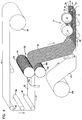
- Fig. 4 one example of a manufacturing process for making a media strip corresponding to strip 1, Fig. 1 is shown.
- facing sheet 64 and the fluted (corrugated) sheet 66 having flutes 68 are brought together to form a media web 69, with an adhesive bead located therebetween at 70.
- the adhesive bead 70 will form a single facer bead 14, Fig. 1 .
- single facer bead is meant to refer to a sealant bead positioned between layers of a single facer; i.e., between the fluted sheet and facing sheet.
- An optional darting process occurs at station 71 to form center darted section 72 located mid-web.
- the z-filter media or Z-media strip 74 can be cut or slit at 75 along the bead 70 to create two pieces 76, 77 of z-filter media 74, each of which has an edge with a strip of sealant (single facer bead) extending between the corrugating and facing sheet.
- the edge with a strip of sealant would also have a set of flutes darted at this location.
- the strips or pieces 76, 77 can then be cut across, into single facer strips for stacking, as described below in connection with Fig. 6 .
- the Z-filter media 74 must be formed. In the schematic shown in Fig. 4 , this is done by passing a flat sheet 92 of media through a pair of corrugation rollers 94, 95. In the schematic shown in Fig. 4 , the flat sheet 92 of media is unrolled from a roll 96, wound around tension rollers 98, and then passed through a nip or bite 102 between the corrugation rollers 94, 95. The corrugation rollers 94, 95 have teeth 104 that will give the general desired shape of the corrugations after the flat sheet 92 of media passes through the nip 102.
- the flat sheet 92 of media After passing through the nip 102, the flat sheet 92 of media becomes corrugated and is referenced at 66 as the corrugated sheet.
- the corrugated (i.e., fluted) media sheet 66 is then secured to facing media sheet 64. (The corrugation process may involve heating the media, in some instances.)
- the process also shows the facing sheet 64 being routed to the darting process station 71.
- the facing sheet 64 is depicted as being stored on a roll 106 and then directed to the corrugated sheet 66 to form the Z-filter media 74.
- the corrugated sheet 66 and the facing sheet 64 are secured together by adhesive or by other means (for example by sonic welding).
- an adhesive line is shown used to secure corrugated sheet 66 and facing sheet 64 together, as the sealant bead 70.
- the sealant bead for forming the facing bead could be applied as shown as 70a. If the sealant is applied at 70a, it may be desirable to put a gap in the corrugation roller 95, and possibly in both corrugation rollers 94, 95, to accommodate the bead 70a.
- the type of corrugation provided to the corrugated media is a matter of choice, and will be dictated by the corrugation or corrugation teeth of the corrugation rollers 94, 95.
- One typical type of flute pattern will be a regular, typically curved, wave pattern corrugation, of straight flutes, as defined herein above.
- a typical regular curved wave pattern used would be one in which the distance D2, as defined above, in a corrugated pattern is at least 1.2 times the distance D1 as defined above.
- the techniques may be applied with curved wave patterns that are not "regular,” including, for example, ones that do not use straight flutes.
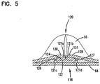
- Fig. 4 shows, in cross-section, one of the flutes 68 after darting and slitting.
- a fold arrangement 118 can be seen to form a darted flute 120 with four creases 121a, 121b, 121c, 121d.
- the fold arrangement 118 includes a flat first layer or portion 122 that is secured to the facing sheet 64.
- a second layer or portion 124 is shown pressed against the first layer or portion 122.
- the second layer or portion 124 is preferably formed from folding opposite outer ends 126, 127 of the first layer or portion 122.
- two of the folds or creases 121a, 121b will generally be referred to herein as "upper, inwardly directed" folds or creases.
- the term “upper” in this context is meant to indicate that the creases lie on an upper portion of the entire fold, when the fold is viewed in the orientation of Fig. 5 .
- the term “inwardly directed” is meant to refer to the fact that the fold line or crease line of each crease 121 a, 121b, is directed toward the other.
- creases 121c, 121d will generally be referred to herein as “lower, outwardly directed” creases.
- the term “lower” in this context refers to the fact that the creases 121 c, 121 d are not located on the top as are creases 121 a, 121b, in the orientation of Fig. 5 .
- the term “outwardly directed” is meant to indicate that the fold lines of the creases 121c, 121d are directed away from one another.
- a an example regular fold arrangement 118 according to Fig. 5 in this disclosure is one which includes at least two "upper, inwardly directed, creases.” These inwardly directed creases are unique and help provide an overall arrangement in which the folding does not cause a significant encroachment on adjacent flutes.
- a third layer or portion 128 can also be seen pressed against the second layer or portion 124.
- the third layer or portion 128 is formed by folding from opposite inner ends 130, 131 of the third layer 128.
- the first layer or portion 122 is formed from an inverted ridge.
- the second layer or portion 124 corresponds to a double peak (after inverting the ridge) that is folded toward, and in preferred arrangements, folded against the inverted ridge.
- Opposite flow ends or flow faces of the media pack can be provided with a variety of different definitions. In many arrangements, the ends are generally flat and perpendicular to one another.
- the flute seals can be formed from a variety of materials.
- hot melt or polyurethane seals are described as possible for various applications. These are useable for applications described herein.
- Fig. 6 schematically there is shown a step of forming a stacked z-filter media pack from strips of z-filter media, each strip being a fluted sheet secured to a facing sheet.
- single facer strip 200 is being shown added to a stack 201 of strips 202 analogous to strip 200.
- Strip 200 can be cut from either of strips 76, 77, Fig. 4 .
- application of a stacking bead 206 is shown, between each layer corresponding to a strip 200, 202 at an opposite edge from the single facer bead or seal. (Stacking can also be done with each layer being added to the bottom of the stack, as opposed to the top.)
- each strip 200, 202 has front and rear edges 207, 208 and opposite side edges 209a, 209b.
- Inlet and outlet flutes of the corrugated sheet/facing sheet combination comprising each strip 200, 202 generally extend between the front and rear edges 207, 208, and parallel to side edges 209a, 209b.
- opposite flow faces are indicated at 210, 211.
- the stacking bead 206 is positioned adjacent the upstream or inlet face 211; in others the opposite is true.
- the flow faces 210, 211 extend between opposite side faces 220, 221.
- the stack 201 shown being formed in Fig. 6 is sometimes referred to herein as a "blocked" stacked media pack.
- the term "blocked” in this context is an indication that the arrangement is formed to a rectangular block in which all faces are 90° relative to all adjoining wall faces. Alternate configurations are possible. For example, in some instances the stack can be created with each strip 200 being slightly offset from alignment with an adjacent strip, to create a parallelogram or slanted block shape, with the inlet face and outlet face parallel to one another, but not perpendicular to upper and bottom surfaces.
- stack 201 will be referenced as having a parallelogram shape in any cross-section, meaning that any two opposite side faces extend generally parallel to one another.
- FIGs. 7-21 a first example air cleaner assembly and components described herein, and in US 61/003,215 are depicted schematically.
- air cleaner assembly 300 is depicted in side elevational view.
- the air cleaner assembly 300 includes housing 301 having an inlet side 302 and outlet end 303.
- the precleaner arrangement 306 can, for example, include a plurality of preseparator tubes such as cyclonic separator tubes therein, not depicted in Fig. 7 . Such a precleaner would typically have a dust flow outlet therein, which either allows for gravity removal of dust separated by the precleaner arrangement 306, or attachment of a scavenge hose. An outlet 307 for a scavenge hose is indicated at one optional location.
- Air to be filtered generally passes into air cleaner assembly 300 by first passage into (optional) precleaner arrangement 306 in the direction of arrow 310. After passage through the precleaner arrangement 306, the air enters the air cleaner housing 301, through inlet side 302.
- an air filter cartridge including a media pack comprising a stack of z-filter strips, generally in accord with previous descriptions. That is, each strip would typically comprise a fluted sheet secured to a facing sheet, with the strips arranged in a stack having appropriate sealing to ensure that air passing into one flow face must pass through the media before it passes through the opposite flow face. Principles discussed above in connection with Figs. 1-6 can be used for this.
- a z-filter media pack 315 is depicted, schematically, in phantom lines positioned generally as oriented within an interior of housing 301.
- the media pack 315 has an inlet flow face 316 and an opposite outlet flow face 317.
- the media pack 315 has first and opposite sides 318, 319, extending between flow faces 316, 317.
- Media pack 315 can comprise a stack of strips of z-filter media, with flutes extending in a direction between the inlet flow face 316 and outlet flow face 317. As the air exits flow face 317, then, it will have been filtered by the z-filter media pack 315.
- the air, filtered, After exiting the media pack 315, the air, filtered, enters a portion of clean air region 320 and eventually leaves the cleaner housing 301 via an air cleaner housing outlet arrangement or outlet 321 at outlet end 303.
- an optional safety element or secondary element is provided in region 320, through which the air must pass before it exits outlet 321.
- Filtered air exiting outlet 321 is generally indicated by arrow 311.
- Fig. 7 is generally schematic. The figure is intended to provide an overall understanding of an orientation of a arrangement according to the present disclosure.
- media pack 315 is non-removably secured within a filter cartridge housing, discussed below.
- the air filter cartridge comprising the combination of the media pack 315 and an air filter cartridge housing, is a service part, removably positioned within an interior 301i, of air cleaner housing 301.
- the air cleaner assembly 300 is depicted in Fig. 7 in a vertical orientation, with inlet side 302 directed upwardly.
- An air cleaner using analogous principles could be differently, for example it could be oriented with an inlet end directed toward a side rather than upwardly. Alternate orientations for the assembly 300 may be benefited by alternate locations for dust exit outlet 307 from the optional precleaner 306.
- Fig. 8 a schematic, bottom plan view generally taken toward end 312 of housing 301, Fig. 7.
- Fig. 8 is provided in part to orient the cross-sectional view of Fig. 12 , discussed below.
- the housing 301 can be seen to have first and second opposite sides 301a, 301b, and first and second opposite ends 301c, 301d.
- end 301d comprises a removable access cover, for service access to an interior 301i of housing 301.
- Fig. 9 is an outlet end elevational view generally taken in the direction of outlet end 303, Fig 7 .
- air cleaner outlet end 303 is viewable.
- precleaner 306 positioned over inlet side 302 of housing 301.
- media pack 315, with inlet flow face 316 and opposite outlet flow face 317 is depicted in phantom lines.
- the example air cleaner housing 301 generally includes first and second, opposite, sides 301a, 301b with portions 321', 322, respectively, extending generally parallel to one another, in extension from inlet side 302 toward an air cleaner housing end 312 opposite inlet side 302.
- end 312 is a curved end 325 and has a larger dimension D 1 thereacross, than a distance D 2 between opposite portions 321',322.
- curved end 325 is positioned with portion 322 engaging the curved region 325 generally tangentially. In the example depicted, however, portion 321' does not engage curved end 325 tangentially.
- clean air region 320 is generally positioned within curved, closed, region 325 of housing 301.
- FIG. 10 a side elevational view is provided taken in the general direction of end 301d, Fig 8 .
- the side view of Fig.10 is an opposite side or end 301d from the end 301c viewable in Fig. 9 .
- the end 301d viewable in Fig. 10 is generally referred to as an access end 330.
- the access end 330 includes a removable air cleaner housing access cover 331 secured thereover.
- An example method of securement for the access cover would be to use latches, indicated schematically at 333.
- An alternate, usable, approach to securement is discussed below in connection with the embodiment of Figs. 22-31 .
- projection region in access cover 331, toward the viewer is depicted.
- An opposite side of projection 335 comprises a receiver region or handle recess, for receipt therein of an optional handle portion of a serviceable filter cartridge, as discussed below.
- a top plan view of air cleaner assembly 300 is depicted.
- the view of Fig. 11 is generally taken toward precleaner 306.
- Individual cyclonic separator tubes 338 are schematically represented. In operation, as air enters the cyclonic tubes 338 ( Fig. 11 ), a cyclonic flow pattern in each is generated, with some dust being separated and removed through outlet 307. The remaining air is then directed into the air cleaner housing 301 for filtering, by passage through the media pack 315, previously referenced.
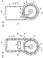
- FIG. 12 Interior features of air cleaner assembly 300 can be understood by review of Fig. 12 , a cross-sectional view taken generally along line 12-12, Fig. 8 .
- precleaner 306 is not depicted with separator tubes 338 therein, for convenience. All that is viewable in Fig. 12 is outer shell or housing 306a of the precleaner 306.
- access cover 331 is removable from a remainder of housing 301, for service access to interior 301i of the housing 301.
- first or main filter cartridge 340 and an optional safety or secondary filter cartridge 341.
- the first or main filter cartridge 340 includes an air filter cartridge housing 342 with a media pack 315, having an inlet flow face 316 and an opposite outlet flow face 317, non-removably secured thereto. That is, the main filter cartridge 340, the media pack 315 is non-removably secured within a filter cartridge housing 342.
- the filter cartridge housing 342 includes an inlet end or face 345 in alignment with the inlet flow face 316 of the media pack 315.
- align in this context, it is meant that for the example air flow entering filter cartridge housing 342 through inlet end 345 will enter inlet flow 316 of the media pack 315, without turning.
- filter cartridge housing 342 includes an outlet arrangement 346 in the housing 340, oriented such that air exiting the outlet flow face 317 of the cartridge 315 must turn, generally orthogonally to flow through the filter media pack 315 and thus to exit the air cleaner housing 301 though outlet 321.
- the filter cartridge 340 is not. Rather, in the example filter cartridge 340 is configured so that in passing from the inlet end 345 to the outlet arrangement 346, after passage through the media pack 315, the air must turn to exit in a general direction orthogonal to flow into the inlet end 345.
- filter cartridge 340 includes a housing 342 defining an interior 343 in which the media pack 315 is positioned. More specifically, the example filter cartridge housing 342 is defined by a shell member 344 and first and second, opposite, side members 350, 351, respectively.
- the media pack 315 is non-removably secured within the shell member 344, and thus the filter cartridge housing 342, for example with an adhesive or sealant.
- the side members 350, 351, as discussed below, are mounted on opposite sides 318, 319 of the media pack 315, sealing and closing the sides 318, 319; and, also, are mounted over opposite sides or ends of the shell member 344, as discussed below.
- Side member 350 includes a first section 352 which includes a side 318 of the media pack 315 sealed thereby. Side member 350 further includes a section 355 having air flow outlet arrangement (aperture) 346 therein, for outlet flow from the cartridge 340. This is described, further, below, in connection with other figures.
- Side member 351 includes a section 362 which generally encloses: a side 319 of the media pack 315 opposite the side 318; and, a side of shell member 344.
- Projection 363, in side member 351 projects in a direction opposite side member 350 comprises an optional handle member, for manipulating cartridge 340.
- the handle member 363 can have a variety of shapes, and may in some instances include an aperture therethrough or an undercut, to facilitate gripping.
- handle member 363 is a projection with no apertures therethrough and no undercuts therein.
- side member 351 further includes peripheral portion or perimeter 364 discussed further below. Extending across region 365, and thus closing side member 351 is provided a projection arrangement 366.
- the projection arrangement 366 includes a portion 366b, closed by end 366e, projecting into interior cartridge 340, as discussed below.
- the projection arrangement 366 comprises a secondary filter cartridge support, oriented to engage and support an end of optional secondary cartridge 341, as discussed below.
- the example projection arrangement 366 depicted includes an axially, outwardly, projecting central receiving recess 367 therein, projecting generally away from outlet arrangement 346.
- the projection arrangement 366 can comprise a preformed member, secured within side member 351, when a remainder of side member 3 51 is molded or formed, for example, when member 351 is molded-in-place. This too is discussed further below.
- втори ⁇ ное кар ⁇ иров 340 downstream from first air filter cartridge 340 is provided optional secondary cartridge 341 including media 371, in the example surrounding an open filter interior 372.
- the secondary or safety cartridge 341 is positioned over outlet 321 so that air exiting outlet flow face 317 of the media pack 315 must pass through the media 371 of the optional secondary cartridge 341, before the air can exit outlet 321.
- secondary or safety cartridge 341 has first, open, end 341b; and, second, closed, end 341a.
- the open end 341b allows for flow of filtered air from the secondary or safety cartridge 341, outwardly through outlet 321 in the air cleaner housing 301.
- the second closed end 341a generally does not permit passage of air therethrough.
- the media 371 is provided in a generally conical shape tapering downwardly in extension from end 341b to end 341a.
- a seal arrangement 375 At the open end 341b, is positioned a seal arrangement 375, discussed below.
- the seal arrangement 375 is oriented to form a seal directed against a portion of housing 301.
- secondary filter cartridge 341 includes end cap 376 with an outward, axial, projection 377 therein, which is received, in a mating and supporting manner, within recess 367.
- axial when used in connection with projection 377, is generally meant to refer to a projection 377 oriented generally aligned with a central axis M through the secondary cartridge 341.
- the term “outward” in connection with the axial projection is meant to refer to a direction of projection generally away from end 341b.
- air cleaner housing 301 includes inwardly directed flange 470.
- Flange 470 includes an outer surface 470o and a inner surface 470i.
- seal member of the filter cartridge housing 342 is configured to engage and seal to outer surface 470o of housing flange 470.
- seal member 375 on secondary or safety filter cartridge 341, is configured to engage and seal against inner surface 470i of flange 470.
- flange 470 can be characterized as sealing flange surrounding outlet 321.
- FIG. 12A a schematic, cross-sectional view taken along line 12A-12A, Fig. 12 .
- Cartridge 340 is positioned with inlet end 345 directed upwardly.
- media pack 315 is oriented with inlet face 316 directed upwardly, corresponding to (i.e. alignment with) inlet end 345 of cartridge 340.
- Outlet face 317 of the media pack 315 is shown directed downwardly, i.e. in a direction opposite inlet flow face 316.
- air filter cartridge 340 does not include an outlet end opposite inlet end 345. Rather, the outlet arrangement for filter cartridge 340, as indicated in Fig. 12 at 346, is a side outlet, and not an outlet in a direction opposite the inlet end 345.
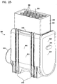
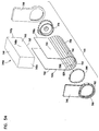
- FIG. 13 an exploded, schematic view of assembly 300.
- cartridge 340 including media pack 315 is shown separated from interior 301i of housing 300, with safety cartridge 341 retained in place.
- the cartridge inlet end 345 and the media pack inlet flow face 316 are generally aligned, in overlap.
- outlet flow face 317 of the media pack 315 is not aligned in overlap with outlet 346 from the cartridge 340. That is, the inlet end 345 of the cartridge 340 does not face the outlet arrangement 346, in alignment.
- the cartridge 340 includes an internal clean air volume 380 therein.
- the clean air volume 380 is sized to receive, projecting therein, media pack 371 of secondary filter cartridge 341, during installation.
- the air filter cartridge 340 comprises an air filter cartridge housing 342 with a media pack 315 non-removably secured therein, as previously characterized.
- Cartridge 340 is further configured to define clean air volume 380 adjacent the outlet flow face 317 of the media pack 315.
- the space 380 is defined, generally, between the media pack outlet flow face 317 and closed end 344 of housing 342.
- the space 380 occupies a portion of region 320, Fig. 7 , when the cartridge 340 is in installed.
- the housing 342 defines open inlet end 345.
- FIG. 13 it can be seen that air which enters flow face 316 (i.e. inlet face 345 of cartridge 340) is filtered by the media pack 315, and exits face 317. The air is then directed by housing 342 to outlet 346.
- the outlet 346 is aligned with outlet 321, for air flow passage from the air cleaner assembly 300.
- Region 380 within housing 342 is sized sufficiently large to receive the optional safety element 341 therein, when used.
- side member 351 defines perimeter seal member 364.
- the perimeter seal member 364 is sized to seal against end region 301x of housing interior 301i, adjacent housing service access opening 301y, when the cartridge 340 is operably installed. Compression against surface 301x by housing peripheral perimeter seal 364, to accomplish sealing, is provided when access cover 331 is pressed against side member 351 in the general direction of arrow 420, Fig. 13 . That is, as perimeter flange 331x on the access cover 331 presses against end 364x of region 364, member 351 is pressed inwardly, and expands or bulges radially outwardly, in the direction of arrow 421. This will be sufficient to form the seal at region 301x, as described.
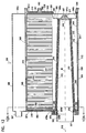
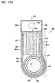
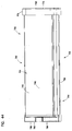
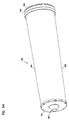
- Fig. 14 is a view of cartridge 340, the orientation being generally analogous to the orientation of the housing 301, Fig. 7 .
- inlet end 345 is shown, with arrow 310 indicating inlet flow.
- Interiorly received media pack 315 is depicted in phantom lines.
- Downstream clean air region 380 is depicted interiorly of the filter cartridge housing 342. Exit air flow from the filter cartridge 340, and thus filter cartridge housing 342, is indicated generally at 311.
- the cartridge 340 is a service part or replacement part. That is, when the air cleaner 300 is used, in due course media pack 315 will become sufficiently loaded with dust to warrant refurbishment or replacement. This is done by replacing the entire cartridge 340, for the example shown.
- the cartridge 340 comprises filter cartridge housing 342 defined by shell member 344 and first and second side members 350, 351.
- the shell member 344 generally wraps around portion of media pack 315 and region 380, but does not extend across inlet end 345, in the view depicted.
- the shell member 344 includes closed end section 344a extending across, and spaced from, outlet face 317 of the media pack 315.
- the shell member 344 further includes a first side 415 toward the viewer in Fig. 14 , and an opposite second side section 416 away from the viewer in Fig. 14 .
- the opposite side section 416 is viewable in Fig. 15 .
- FIG. 15 the view is taken toward closed end section 344a of shell member 344. Here, opposite sides 415, 416 are indicated.
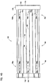
- FIG. 16 a top plan view of cartridge 340.
- the media pack 315 is viewable, exposed an inlet end 345 of the cartridge 340.
- inlet face 316 of the media pack 315 is viewable.
- the depiction is schematic, and there is no specific effort made to depict individual inlet flutes and outlet flutes of the media pack 315.
- the cartridge 340 may include a screen extending across cartridge face 345, and media pack face 316; a screen being represented by phantom lines 430. Further, or alternatively, a grid arrangement or other arrangement can be provided at this location.
- shell side 416 includes an outer or bottom, projection section 416x therein, discussed below.
- the media pack 315 will typically be secured to opposite end edges 415y, 416y, of shell member 344, along regions 440, 441 by an adhesive, for example a hot melt sealant or other sealant material. This would ensure against leakage of unfiltered air between the media pack 315 and the shell member 344.
- an adhesive for example a hot melt sealant or other sealant material. This would ensure against leakage of unfiltered air between the media pack 315 and the shell member 344.
- Fig. 17 is a elevational view of first or main filter cartridge 340 taken generally toward side member 350. The view is generally through outlet arrangement 346, to region 380. At 366a, the inner, closed surface of projection 366, Fig. 12 , is shown. At 367, the axially, outwardly, projecting recess, Fig. 12 , is shown.
- the media pack is indicated in Fig. 17 at 315, by phantom lines.
- air to be filtered would generally enter the cartridge 340 with the direction of arrow 310 and would exit the cartridge through outlet arrangement 346, toward the viewer.
- Fig. 18 a side elevational view of cartridge 340, taken generally toward end member 351.
- Perimeter seal member 364 is shown extending completely around a perimeter of end member 351.
- Handle 363 is viewable, projecting toward the viewer.
- the secondary filter cartridge support is viewable, with recess 367 projecting toward the viewer.
- the cartridge 340 in particular housing 342 and shell member 344, generally has a "d" or "b" shape, depending on which side is viewed.
- this shape will sometimes be referred to herein as a "d/b shape,” or by similar terms.
- the term "d/b shape” is intended to be applicable, even though the actual shape, in Fig. 17 and 18 , includes a curved portion 344a depending downwardly of an end of a straight side portion. In spite of this, the overall shape is reminiscent of a "d” or "b,” and thus the terms are used.
- the shell section 415 engages curved or round rounded end section 344a, tangentially. This is not the case for shell section 416, which provides for outwardly curved section 416x in transition toward curved end section 344a.
- This provides the referenced "b" and/or "d" shape to the shell member 344.
- Such a shape is useful, in general, when the dimension Y of the media pack 315, in Fig. 18 is smaller than the dimension X needed across region 380 to accommodate optional safety cartridge 341, Fig. 13 , or to provide to a desirable sized outlet arrangement 346, Fig. 17 .
- the dimension X references a dimension between outlet face 317 of the media pack 315, and a closed end of the shell 344 (or filter cartridge housing 342).
- the dimension Y is a general dimension through the media pack 315 in a direction both: orthogonal to a general air flow direction therethrough; and, through individual layers or strips of media within the media pack.
- the dimension "Z" is used to refer a distance between opposite sides 415, 416 of the filter cartridge housing 342 (or shell member 344). Typically, the dimension Z will be approximately the same as the dimension Y.
- the dimension X is at least 50% of each of the dimensions Y and Z; usually at least 75% and often at least 90%. In many instances, the dimension X will equal to or greater than the dimensions Y and Z; thus, often the ratios X/Y or X/Z will be at least 1.0, usually each ratio (X/Y and X/Z) is within the range of 1.0-1.7, inclusive; typically 1.0-1.5, inclusive.
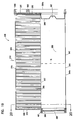
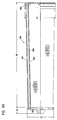
- FIG. 19 a sectional view of cartridge 340, taken generally along line 19-19, Fig. 15 .
- the cross-sectional view of cartridge 340, Fig. 19 is generally analogous to the cross-sectional view of Fig. 12 .
- Fig. 19 internally secured media pack 315, with inlet face 316 and outlet face 317 is viewable, secured within the filter cartridge housing 342.
- the inlet face 316 is shown aligned with inlet face 345 of the cartridge 340.
- Clean air region 380 is viewable, defined under shell member 344 in particular by shell end section 344a.
- Opposite end pieces 350, 351 are shown molded-in-place.
- Side member 350 defines outlet arrangement 346, in seal arrangement 460.
- the seal arrangement 460 is supported by seal support ring 461, to form an inwardly directed radial seal. This seal is sized and configured to form a seal to, and around, an outer surface 470o of flange 470 in the housing, Fig. 12 .
- side member 351 is closed, with: outer seal perimeter 364, handle 363 and projection 366, with recess 367 projecting axially away from outlet arrangement 346.
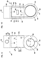
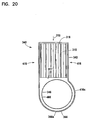
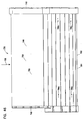
- FIG. 20 a schematic, cross-sectional view taken generally in the direction of line 20-20, Fig. 19 .
- the cross-sectional view is taken through the housing 342, and thus sections 415, 416 can be directly examined, as well projection 416x adjacent end section 344a, of shell member 344.
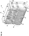
- FIG. 21 an enlarged, side elevational view of safety cartridge 341, Fig. 12 is provided.
- the cartridge 341, Fig. 21 includes media 371 extending between seal arrangement 375, end cap 376.
- Seal arrangement 375 includes an outer surface 375y with seal region 355 thereon, which will form a seal when pushed into an interior surface of flange 470, Fig. 12 .
- End cap 376 includes projection 377 thereon, which is sized to be engaged by, and supported by, support 366.
- the reference 500 depicts a second embodiment of an air cleaner assembly according to the present disclosure.
- the air cleaner assembly 500 includes a pre-cleaner 501 and a main air cleaner assembly 502.
- the air cleaner assembly 500 is depicted in an orientation as would be typical for use. However it is noted in the principles described could be applied with an air cleaner assembly in a different orientation, for example on its side.
- the pre-cleaner 501 includes a housing 505 defining an inlet end 506, and a dust ejector outlet 507.
- the dust ejector outlet 507 in the example depicted is not oriented directed downwardly, and thus would typically be attached to a vacuum dust scavenge system for drawing collected dust out of the pre-cleaner 501.
- the pre-cleaner 501 includes a plurality of cyclonic separator tubes 508.
- the tubes may be as conventional for use in pre-cleaner assemblies. Air would typically enter the assembly 500 in the direction of arrow 510. This would direct the air into inlet end 506 of the pre-cleaner 501. In particular the air would enter the cyclonic tubes 508, and the pre-cleaner 501. Cyclonic tubes 508 would separate out a portion of the dust, which would exit pre-cleaner 501 through outlet 507. The air, after passage through the optional pre-cleaner, would then move into the main air cleaner assembly 502 in the general direction of arrow 511. Within the main air cleaner assembly 502, the air is passed through a main filter cartridge, with filtering. Air is then optionally passed through a secondary or safety filter cartridge. The filtered air is generally directed outwardly from the main air cleaner assembly 502 through outlet 515.
- the main air cleaner assembly 502 includes a housing 516.
- the housing 516 is provided with a mounting pad arrangement 518, by which the air cleaner assembly 500 could be mounted in a vehicle or other equipment.
- the view oriented is generally a top (inlet) and an outlet side, as a perspective view.
- FIG. 23 a second top perspective view of the assembly 500.
- the view is taken toward a side 520 opposite the outlet 515.
- the view is taken toward side 520 which includes a removable service or access cover 521 thereon.
- access cover 521 is removable to allow service access to an internally received filter cartridge.
- the access cover 521 is shown with a handle receiver 525 therein.
- the handle receiver 525 includes a recess on the inside surface of the access cover 521, for receiving, projecting therein, a handle member of a internally received filter cartridge, in use.
- Fig. 24 a bottom plan view of assembly 500.
- pre-cleaner 501 is viewable mounted on main air cleaner assembly 502, and in particular on an inlet end 519 of the housing 516.
- Outlet 515 is viewable, for filtered air exit from the air cleaner assembly 500.
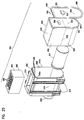
- Fig. 25 exploded perspective view of the air cleaner assembly 500, Figs. 22-24 .
- the view of Fig. 25 is generally analogous in orientation, to the view of Fig. 23 .
- pre-cleaner 501 comprises a shell 505 generally mountable over inlet 519 of housing 516. It is noted that for the particular housing 516 depicted, the inlet 519 is oriented so that air flow therethrough, is generally orthogonal the outlet flow through outlet 515.
- air cleaner housing 516 generally defines interior 516i, in which is received at least a main filter cartridge assembly 540, and in some instances an optional safety cartridge assembly 541, through access opening 516 0 .
- access cover 521 is shown.
- the access cover 521 is shown with an upper end 544 having a plurality of apertures 545 therethrough.
- the apertures 545 are aligned to position over the projections 546, along upper edge 516x housing 516.
- the access cover 521 can be hung by the engagement between projections 546 and receivers 544. Latching closed can then be accomplished with latch member 550.
- Main filter cartridge 540 is a service part, i.e., cartridge 540 is configured to be removed from assembly 500 and be replaced, or be refurbished, in due course.
- the main filter cartridge 540 includes a filter media therein, which would become loaded with contaminant, in time. Sufficiently loaded, the cartridge 540 is removed and is either refurbished or is replaced. Typically it is replaced with a new, but analogous, filter cartridge 540.
- main filter cartridge 540 includes a media pack therein, indicated generally at 630 having an inlet flow face 631 and an opposite outlet flow face 632.
- the media pack 630 may be, in general, analogous to media pack 315, as previously discussed.
- the cartridge 540 includes an inlet end 555.
- the inlet end 555 is a side of cartridge 540 into which inlet air is directed, for filtering.
- Positioned within cartridge 540, to receive inlet air through inlet 555 is the filter media pack 630, discussed below.
- the media pack would typically be permanently (i.e. non-removably) secured within an outer main filter cartridge housing 600 of cartridge 540, discussed below.
- the main filter cartridge 540 includes a perimeter housing seal member 557 around a closed side 558 thereof, positioned to seal against interior 516i the housing 516, when installed, adjacent air cleaner access opening 516o. Compression of the access cover 521 against edge 557x of the seal member 557 will facilitate this. This is discussed further below.
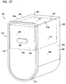
- FIG. 26 a second top perspective exploded view of the assembly 500, in this instance the orientation generally corresponding to that of Fig. 22 .
- cartridge 540 is viewable with inlet end 555.
- aperture 560 for filtered air from filter cartridge 540 is depicted. It can be seen that within the example filter cartridge 540 the air enters through end 555 and exits through aperture 560 generally orthogonal to the entrance. This is discussed further below.
- Fig. 26 Also viewable in Fig. 26 , is optional secondary or safety cartridge 541 comprising media 565 extending between opposite end caps 566, 567.
- end cap 566 is closed, i.e. it includes no aperture therethrough.
- End cap 567 is open and defines an opening 568 therethrough, in gas flow communication with an interior 565i surrounded by media 565.
- the end cap 567 includes an outer perimeter 569 configured to form a housing seal arrangement 570, positioned to engage a portion of the housing 516 and seal there against, in use, as discussed below.
- aperture 560 in the main filter cartridge 540 is an interior surface 573 configured to define a housing seal 575.
- the seal 575 is configured to engage and seal against portion of the housing 516, in use.
- air will enter filter cartridge 540 in the general direction of arrow 580.
- the air will pass through, and be filtered by a media pack 630 using media of the type previously discussed, and generally as shown and discussed below. Filtered air will then exit the main filter element 540 through the aperture 560.
- the cartridge 541 will generally project into an interior 540i of the main cartridge 540 at a location downstream from media pack 630. When this is the case, before the air exits aperture 560, it passes through media 565 into open interior 565i. Then, as the air passes outwardly through aperture 560 it also passes through aperture 568, to leave housing 516 through outlet 515.
- recess 525r defined by projection 525, Fig. 23 , is viewable.
- the recess 525r is sized and shaped to receive projecting therein a filter cartridge handle member 590, not viewable in Fig. 26 .
- the handle member 590 is viewable in Fig 25 .
- cartridge 540 is viewable.
- the cartridge 540 generally comprises a main filter cartridge housing 600 having a sidewall 601 defined by a shell 602.
- Shell 602 defines an open end 603 corresponding to open end 555 of cartridge 540 and to inlet face 631 of media pack 630.
- Housing 600 includes first and second end members 605, 606.
- end member 606 can be viewed as having optional handle member 550 thereon.
- End member 606 also includes peripheral housing seal member 610 thereon.
- the shell 602 generally has first and second, opposite, sides 615, 616 and a closed end section 617.
- media pack 630 is schematically depicted within housing 600, i.e. shell 602.
- the media pack 630 is depicted within an inlet flow face 631 and an opposite outlet flow face 632.
- the media pack 630 will be adhesively secured, and typically sealed, to opposite side sections 615, 616 of shell 602, along edges 615a, 616a, respectively.
- the media pack 630 is typically non-removably secured within filter cartridge housing 600.
- cartridge 540 is again viewable, the view being taken generally toward end 605 of housing 600.
- the end 605 can be a molded-in-place member.
- the end 605 can comprise, for example, a molded-in-place foamed polyurethane member.
- end 605 is viewed as having therein, aperture 560 defining interior surface 573 with housing seal arrangement 575 thereon.
- Interior 540i of main cartridge 540 is designated.
- region 670 a clean air region within interior 540i is designated.
- the clean air region 670 is generally oriented between inlet flow face 631 of media 630, and shell 602, in particular closed end 617 of shell 602.
- Fig. 29 an end elevational view taken toward end member 605, Fig. 28 .
- shell 602 defined by opposite side pieces 615, 616 and closed end 617, for the example shown, generally defines a "u"-shape.
- the media pack 630 is positioned between opposite side sections 615, 615, typically secured thereto with a adhesive, for example a sealant.
- End member 605 can be a molded-in-place end member, closing a side end of the media pack and a side of the end shell 602, but for passage of aperture 560 therethrough, into clean air region 670.
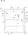
- a side elevational view of cartridge 540 is depicted. The view be taken generally toward side 615 of shell 602. Dimension X, extending across clean air region 670 between outlet flow face 632 of interiorly received cartridge 630 and closed end 617 of shell 602 is shown, schematically.
- end member 606 is depicted having an internal projection shown in phantom lines, at 690.
- Internal projection 690 projects into clean air region 670, from a remainder of end member 606.
- the projection 690 can be molded into the end member 606, or can comprise a preform made, and then put in place in end member 606, when end member 606 is molded-in-place.
- End member 606 can comprise foamed polyurethane, molded-in-place; and, projection 690 can comprise, in some instances, a preform, for example, a plastic member embedded within a remainder member 606 when formed.
- the projection 690 generally comprises a secondary cartridge support member, and will engage, Fig. 26 , end 566 secondary cartridge 541, during installation, to support end 566. This can be conducted, for example, by projection 690 extending around end 566, or by projection 590 being sized to project into a recess formed in end 566.
- side member 605, Fig. 30 will be referred to as "open” due to aperture 560 extending therethrough as a filter cartridge outlet flow aperture.
- end member 606 will be generally be characterized as a “closed” member, as it has no apertures therethrough.
- end members 605, 606 When end members 605, 606 are molded-in-place, they would typically include embedded therein, respectively, opposite sides 630a, 630b of media pack 630. Thus, end members 605, 605 seal closed sides 630a, 630b of media pack 630.
- peripheral seal member 610 includes an outer end surface 610x.
- surface 610x When the access cover 521, Fig. 26 , is pushed in place, surface 610x is engaged and will compress, bulging region radially, outwardly, in the general direction shown at arrow 695. This will facilitate sealing against inner surface 516i; of housing 516, Fig. 25 , in a manner analogous to that previously discussed for a previously described embodiment.
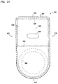
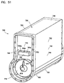
- Fig. 31 a view taken toward end member 606 is depicted.
- Assembly cartridge 540 for example , would be analogous to that of cartridge 340, as follows.
- Media pack 630 would be preformed.
- Shell 602 would be provided in the selected shape, for example u-shape, and media pack 630 would be positioned between side sections 615, 616, typically sealed thereto with an adhesive. There resulting combination would then be used in a molding process, to form opposite side member 605, 606. Either one of the side members 605, 606 could be formed first.
- a usable foamed polyurethane, for molded-in-place portions of members 605, 606 can comprise a material formed with as molded density of not greater than 30 lbs/cu.ft. (0.46 g/cc), typically not greater than 15 lbs/cu.ft (0.24 g/cc), and sometimes no greater than 10 lbs/cu.ft (0.16 g/cc).
- the overall resulting material would typically be formed with a hardness, shore A, of no greater than 30, typically no greater than 25 and often within the range of 12-20. It is noted that in some applications alternate densities and hardnesses can be used. However, the ranges stated will be typical, for many applications.
- the reference numeral 700, Fig. 32 generally designates an improved air cleaner assembly according to the present disclosure.
- the air cleaner assembly 700 generally comprises a housing 701.
- the housing 701 includes: first and second, opposite, sides 702, 703; an access cover end 704; and, an opposite, not viewable in Fig. 32 , outlet end 705.
- the housing surface includes a inlet (top) end 706, normally directed generally upwardly when housing 701 is installed; and, a closed (bottom) end opposite inlet end 706, the closed end generally being indicated at 707.
- the closed end 707 will be directed downwardly or substantially downwardly in installation.
- the particular air cleaner assembly 700 does not include a precleaner positioned over inlet end 706.
- a precleaner can be used.
- the precleaner can be in accord with the precleaner previously discussed herein, although alternatives are possible.
- the air cleaner assembly 700 can be in general accord with air cleaner assemblies previously described herein.
- access cover end 704 is typically provided with a removable access cover 710 thereon that, when removed, provides for service access to an interior of housing 701.
- the particular access cover 710 depicted is secured in place by a latch arrangement, in the example depicted comprising a plurality of latches 711, although alternatives are possible.
- the particular access cover 710 depicted is completely removable from a remainder of housing 701, during servicing, although alternatives are possible.
- the housing 701 when oriented with inlet end 706 depicted upwardly and opposite closed end 707 directed downwardly, when viewed from the side, the housing 701 generally has a b/d-shape, (or b/d-shaped).
- the shape is generally a "d-shape.”
- alternative shapes including, for example, u-shapes, are possible.
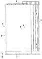
- FIG. 33 a side elevational view of air cleaner assembly 700 is taken at an end opposite that viewable in Fig. 32 .
- the view is taken toward outlet end 705.
- the end view of Fig. 33 shows a generally "b-shape" for the housing 701.
- AA 164.4 mm
- AB 116.1 mm
- AC 350 mm
- AD 61 mm
- AE 200 mm.
- outlet end 705 includes an air flow outlet 720 thereat, for filtered air to leave air cleaner assembly 700, and to be directed to downstream equipment, such as, eventually, an air intake for an internal combustion engine.
- bottom end 707 includes a central lower projection 707p thereon. It will be understood from further description below, that the central projection 707p generally extends across housing 701 between ends 704, 705, and provides a lower trough in the housing 701. Comparing Figs. 32 and 33 , it can be seen that it is reasonable to characterize the housing shape as a "d/b-shape", in spite of the presence of the of the projection 707p; and the term "d/b-shape" and variants thereof, as used herein, is meant to include within its scope a configuration such as that shown in Figs. 32 and 33 .
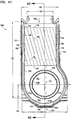
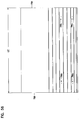
- a side elevational view of air cleaner assembly 700 is provided, the view being taken generally toward side 703, with portions of side 703 being broken away to depict internal detail.
- housing 701 will be a molded plastic component, and thus strengthening ribs 726 are shown in the housing 701.
- air flow inlet 730 for air to be filtered entering housing 701.
- air cleaner assembly 700 is depicted with no precleaner associated therewith. If a precleaner were used, it would typically be positioned over air flow inlet 730, analogously to previously described embodiments.
- frame member 732 over interior portion of outlet 720 is viewable.
- a portion of internally positioned main air filter cartridge 735 is also viewable, as is a portion of internally received safety filter cartridge 736.
- frame member 732 projects inwardly to housing 701, from outlet 720.
- Frame member 732 comprises a plurality spaced support 732a, tapering at narrow end 732b, in extension from outlet 720 inwardly of housing 701.
- Frame member 732 can assist in centering the open end of a safety element 736 or a main filter cartridge 735 inserted into air cleaner housing 701 through end 704, when access cover 710 is removed.
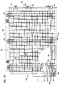
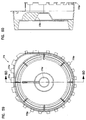
- FIG. 35 a view of air cleaner assembly 700 taken generally toward top, inlet, end 706.
- the view is generally taken through inlet 730 to an interior 701i of housing 701.
- the view is schematic and at inlet end features for an internally received filter cartridge 735 are not detailed, inside inlet 730.
- the reference numeral 735 is used to indicate the general location of the internally received filter cartridge.
- housing 701 includes a bottom section 739, comprising projection 707p with a drain aperture arrangement 740 therein.
- the drain aperture arrangement 740 comprises first and second spaced drain apertures 741, although an alternate number of drain apertures and location of drain apertures can be used.
- the drain aperture arrangement 740 comprises one or more drain apertures 741 through bottom 739 of housing 701. Should water collect within an interior 701i of housing 701, it will generally drain toward projection 707p, along an interior of bottom 739, and outwardly through drain aperture arrangement 740.
- the apertures 741 depicted, are positioned at approximate opposite ends of bottom 739 so that if the housing 701 is slanted toward one side or other, of the sides 704, 705, the water will still drain.
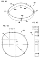
- Fig. 37 a second view analogous to Fig. 34 is provided, free of dimension lines for easier inspection. Features previously identified are indicated by the same reference numerals.
- air cleaner assembly 700 is depicted in a top perspective view, generally directed toward access end 704. Features previously identified are indicated by like reference numerals.
- FIG. 39 a schematic exploded perspective view of air cleaner assembly 700 is taken, generally toward upper inlet 706 end toward and also toward access end 704.
- Individual componentry depicted in Fig. 39 includes housing 701 (indicated as a remainder of the housing minus the access cover 710); access cover 710; main filter cartridge 735; and safety or secondary filter cartridge 736.
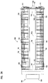
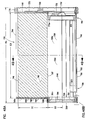
- FIG. 40 a cross-sectional view of air cleaner assembly 700 is depicted.
- main filter cartridge 735 can be seen to comprise a cartridge housing 744 including a media pack 745 having an inlet flow face or end 746 and an opposite flow face outlet end 747.
- the cartridge housing 744 comprises: opposite end members 748, 749; and, outer shell 750.
- the cartridge housing 744 defines an interior volume 744i in which the media pack 745 is positioned; and, the outlet end interior space 751 sized and positioned to receive safety cartridge 736 projecting therein. This is analogous to previously described embodiments. (The media pack 745 can be a stacked, blocked, media pack as previously described).
- air to be filtered will be directed into inlet face 746 of media pack 745.
- the media pack 745 can, in general, comprise a stacked media pack of z-filter strips, as previously described.
- the air will be filtered as it flow through flutes extending between faces 746, 747, since the flutes (media pack) will be sealed appropriately to cause the air to need to pass through the media, to exit flow face outlet end 747.
- the air exiting flow face outlet end 747 will then be directed into an interior 736i of safety cartridge 736, by passage through media 755 of secondary or safety cartridge 736.
- the air is then directed in the general direction of arrow 759 outwardly through cartridge housing outlet 760 and through air cleaner housing outlet 720. It is noted that this air flow direction is also through support member 732.
- outlet flow from air cleaner assembly 700 also involves outlet flow though outlet 760 of the cartridge housing 744 of main filter cartridge 735; and, through outlet end 761 of secondary or safety cartridge 736.
- Fig. 40 it is noted that when access cover 710 is removed, by release of latches 711, member 749 of main filter cartridge 735 will be viewable. By grasping handle member 765, cartridge 735 can be removed from interior 701i of housing 701. This will leave safety cartridge 736 in place, during servicing, if desired. Of course safety cartridge 736 can also be removed from housing 701 if desired.
- cover 710 includes a handle recess 765r therein, for projection therein of cartridge handle 765.
- housing 701 defines an outlet end 767, which provides a service access end for installation or removal of cartridge 735 and secondary cartridge 736. It is also noted that, as discussed below, at closed end 749, main filter cartridge 735 includes a peripheral seal member 770 which, under compression from access cover 710, by latches 711, will press against housing access cover 710 and housing end 767, forming a seal thereat, inhibiting air and outer leakage to housing interior 701i, during use.
- peripheral seal member 770 which, under compression from access cover 710, by latches 711, will press against housing access cover 710 and housing end 767, forming a seal thereat, inhibiting air and outer leakage to housing interior 701i, during use.
- a housing seal flange 705, or flange arrangement, in housing 701, in particular in end 705, for sealing cartridges 735, 736 thereto, is viewable in cross-section.
- FIG. 41 a cross-sectional view taken generally along line 41-41, Fig. 40 . It is noted that in Fig. 41 , a cross-sectional line indicating the cross-section of Fig. 40 , (i.e. line 40-40) is depicted.
- shell 750 of housing 744 of main filter cartridge 735 is viewable.
- Shell 750 (and thus housing 744) can be seen to have opposite sides 775, 776, and a curved or arcuate end 777.
- the end 777 will be considered arcuate, even if it comprises short straight sections arranged in an arc).
- Further shell 775 defines an open access end 778 opposite curved end 777, allowing for air flow entry into inlet face 746 of media pack 745.
- the curved end 777 can be seen to be arcuate, and to have a bottom 777b and upwardly curved opposite sides or side portions 777c.
- dimension D 6 generally corresponds to a dimension X across a closed end section 751 of the housing 744, downstream from the media pack 745.
- the dimension D 5 generally corresponds to a dimension Z between an opposite side section 775, 776 of the shell 750, where the shell engages the media pack 745, thus it also corresponds to a dimension Y through the media pack 745 in a direction perpendicular to gas flow therethrough and also perpendicular to the strips of media.
- the dimension X (corresponding to D 6 , Fig. 41 ) in a typical arrangement is at least 50% of a dimension D 5 (corresponding to dimensions Y or Z as previously described).
- the ratio of X/Y or X/Z is at least 0.5, usually at least 0.75, and typically at least 0.9. In typically arrangements X/Z will be at least 1.0 and not greater than 1.7; and, usually an amount within the range of 1-1.5, although are alternatives are possible.
- the dimension X/Z i.e. D 6 /D 5 is approximately 1.3).
- side 775 is generally tangential to curved end 777, however side 776 is not tangential to curved end 777.
- a portion of safety cartridge 736 is shown in cross-section.
- bottom end 739 in which drain arrangement 740, Fig. 36 is depicted can be seen as a lowermost, dropped, section or trough 707p.
- DA 164.4 mm
- DB 116.1 mm
- DC 350 mm
- DD 61 mm
- DE 200 mm.
- FIG. 42 an end elevational depiction of main air filter cartridge 735 is depicted.
- the view of Fig. 42 is generally toward closed end member 749.
- Closed end member 749 includes an overmold (molded-in-place) portion 775 and a pre-form closed portion 776.
- the overmold portion 775 will typically be molded-in-place, for example from a material such as a foamed polyurethane.
- overmold portion 775 is molded-in-place, in general it will seal a end of an enclosed media pack, and close an end of the shell, while securing pre-form end closure portion 776 in place.
- the polyurethane used for overmold portion 775 will generally comprise a foamed polyurethane as previously characterized herein for member 605. 606, of cartridge 540.
- end member 749 includes an outwardly directed handle portion 765 thereon, projecting outwardly toward the viewer in the view of Fig. 42 .
- Further overmold portion 775 include peripheral rim region 778, adjacent end 749.
- the cartridge 735 includes a cartridge housing 744 having an inlet end 780, and an opposite (bottom) end 781, a first side 782, and a second, opposite, side 783.
- End 780 corresponds to an inlet into which air is directed during entry into cartridge 735.
- Outlet flow from cartridge 735 is through end member 748 opposite end member 749.
- the main filter cartridge 735 has a general shape, when viewed from an end, corresponding b/d (or d/b)-shape. It is noted alternate shapes, for example a u-shape, can be used.
- FIG. 43 a view directed toward filter cartridge 735, and housing cartridge 744, from an end 748 opposite end 749.
- End 748 includes a overmold (molded-in-place) portion 785.
- the overmold portion 785 closes an end of the media pack 745 adjacent thereto, closes an end of the shell 750 adjacent thereto and defines outlet 760.
- outlet 760 is surrounded by seal member 790, which forms housing seal member on cartridge 735.
- the housing seal member 790 generally, forms a seal with housing 701, around cartridge outlet 760, when cartridge 735 is properly installed in housing 701.
- the particular housing seal member 790 depicted is configured to form an inwardly directed seal, against inwardly directed radial seal surface 791 of member 790.
- surface 791 does not simply define a circular perimeter, but rather a perimeter, seal surface shape that includes an arcuate section 791c, on one side, with an opposite side 791d including a central vertex 791v opposite a center of arcuate section 791c and engaged with arcuate section 791c by two, straight, tangential side sections 791, 791b extending at approximately right angles to one another, away from central vertex 791v.
- This shape for seal surface 791, and member 790 generally comprising: one arcuate side and an opposite side having central vertex with two straight sections engaging the arcuate side, provides for a relatively large outlet flow aperture 760, for escape of filtered air from interior 735i of cartridge 735.
- side 782 extends generally tangentially, with the curved bottom section 795 of the cartridge 735 (and hosing 744); and, the side 783 does not engage curved bottom section 795 tangentially.
- alternate possibilities can be used, including for example, a u-shape as discussed above.
- Fig. 44 a top plan view of filter cartridge 735 of main cartridge housing 744.
- the view is generally directed toward top end or inlet 781.
- media pack 745 Positioned within inlet end 781, would be provided media pack 745, Fig. 40 .
- the surface viewable would be inlet flow face or inlet end 746 of media pack 745; detailed features of media pack 745 not being drawn in the schematic of Fig. 44 .
- the media pack 745 would comprise strips of single facer material extending between, and with opposite sides sealed by, opposite end members 748, 749.
- a portion of shell 750, for cartridge 735, is depicted, extending between end members 748, 749.
- a bottom plan view of cartridge 735 and main cartridge housing 744 is shown.
- a portion of shell 750 is also seen extending between end members 748, 749.
- the portion of shell 750 generally corresponds to a curved bottom 795, adjacent bottom 781 of cartridge 735.
- curved bottom 795 includes an aperture arrangement 796 therethrough, the aperture arrangement 796 depicted comprising apertures 796.
- aperture arrangement 796 comprises a first arrangement 796a positioned generally adjacent, to and spaced from, end member 748; and, a second arrangement 796b positioned adjacent to, and spaced from, end member 749.
- the aperture arrangement 796 is configured to allow drainage of water that may collect within an interior of shell 750, outwardly, therefrom. It is noted that the apertures 796 extend through shell 750 at an interior region corresponding to a clean air region of cartridge 735, downstream of media pack 745.
- each of the arrangements 796a and 796b includes a bottom most aperture, aperture 796x, 796y respectively; and, each of arrangements 795a, 795b includes additional apertures 795c positioned in portions (i.e. curved side portions 777c, Fig. 41 ) of shell 750 curved upwardly from bottom 795.
- the additional apertures 795c provide ensures that drainage will occur, even if the cartridge 735 is tilted from an actual vertical orientation, Figs. 42 and 43 .
- the bottom central apertures 796x, 796y will ensure the drainage occurs when the cartridge 735 is oriented vertically as shown in Figs. 42 and 43 .
- Positioning aperture arrangements adjacent, but spaced from, opposite end member 748, 749 ensures that drainage will occur even if the cartridge 735 is tipped downwardly toward end member 748, or tipped downwardly toward end member 749.
- Fig. 46 a side elevational view of cartridge 735 is provided. A portion of shell 750 can be seen extending between end members 748, 749. Apertures 796c can be seen. The view of Fig. 46 is generally toward side 783, Fig. 43 .
- Fig. 47 a side elevational view of cartridge 735 taken toward side 782, i.e. the side opposite side 783, is viewed. Apertures 796c are viewable.
- a cross-sectional view of cartridge 735 is viewable.
- media pack 745 having inlet end 746 and outlet end 747 is viewable, positioned within shell 750, of main filter cartridge 744, and extending between members 748, 749.
- seal surface 791 can be seen to be tapered, having a central step or rib feature 791r which will provide for maximum compression, when pushed over an outlet tube of housing 701. It also noted that embedded within housing seal member 790 is provided support ring 800. The support ring 800 will form a pressure backing, for seal surface 791, when pushed around an outlet tube.
- member 748 comprising overmold 785, can be continuous in forming section 804 closing end 745x of media pack 745; and, housing seal member 790, defining an outlet for clean air from interior 735i of cartridge 735 (or interior 744i of cartridge housing 744).
- end member 749 can be seen to comprise overmold 775 defining outer perimeter seal 778 and handle member 765, while also securing in place preform 776.
- Preform 776 comprises a secondary support projection including an outer sidewall 776s (or inwardly projecting peripheral ring) projecting into interior 735i of cartridge 735, in particular into clean air volume 750i defined by curved end 795 of shell 750.
- the central interior portion of preform 776 is a closed end of the support projection, directed toward the air filter outlet flow aperture760, includes a central recess therein forming an axially outwardly directed receiver 776r surrounded by sidewall 776s and directed away from outlet 780.
- the receiver 776r is positioned to receive, projecting therein, a projection portion on a safety or secondary cartridge when installed within region 776x, as discussed below.
- FIG. 48B an enlarged fragmentary view of a selected portion of Fig. 48A .
- seal support ring 800 is shown embedded with region 790. It is also shown that support ring 800 engages an end or side edge portion 750e of shell 750, creating an axial bearing of ring 800 against shell 750, at ends thereof.
- FIG. 49 a cross-sectional view of cartridge 735, taken generally along line 49-49, Fig. 48A .
- outlet flow aperture 760 is viewable, having a shape with a curved or arcuate side 791c, and an opposite side with a central vertex 791v, and (straight) side sections 791a, 791c.
- the sides 791 a, 791 c generally engaging, tangentially, arcuate side 791c.
- the view of Fig. 49 is of outlet flow aperture 760 from an interior 735i of cartridge 730.
- shell 750 can be seen as having opposite sides corresponding to cartridge sides 782, 783; side 782 engaging curved bottom 795 of shell 750 tangentially; and, side 783 non-engaging curved bottom 795 tangentially, but extending generally parallel to side 782. Again, alternate shapes are possible.
- media pack 745 having inlet flow face or end 746 and outlet flow face or end 747, opposite end 746, is viewable positioned within interior 735i of cartridge 735 (or interior 744i of main cartridge housing 744). It is noted that adjacent face 746, at regions indicating generally at 805, the media pack 745 would typically be potted to, or i.e. sealed to, sides 782, 783 of shell 750. Of course at the opposite ends, the media pack 745 would generally be embedded within molded-in-place portions of end members 748, 749.
- FIG. 50 a side elevational view of cartridge 735 generally directed toward end member 748.
- the cross-section line 48A-48A, for Fig. 48A is indicated.
- cartridge 735 is viewable in a perspective, generally toward member 749 and top or inlet end 780.
- Preform 776 is viewable within overmold 775.
- the preform 776 can be seen to have an outwardly directed cone 810, which defines an interior receiver 776r, Fig. 48A .
- Flange 811 is provided extending toward handle 765 from projection 18.
- Flange 811 generally provides for indexing during a manufacture step.
- handle member 765 is shown with apertures 765a therein.
- shell 750 (and main cartridge housing 744) can be viewed as having opposite sides corresponding to sides 782, 783 of cartridge 735, and lower curved section 795, corresponding to bottom 781.
- FIG. 52 a view of cartridge 735 taken generally toward inlet 780 and outlet end member 748.
- Outlet flow aperture 760 can be seen in end member 748, allowing a view of portion of interior 735i.
- Selected apertures of aperture arrangement 796 are also viewable in shell 750.
- media section 820 is shown positioned within interior 735i, and in particular in shell 750 along an interior 750i thereof, in a position overlapping apertures 796 (A second, analogous, media strip would be positioned adjacent end 749).
- the media section 820 will close aperture 796 to flow of unfiltered air therethrough, into interior 735i, from an exterior environment.
- the media section 820 can be viewed as a media patch, secured within interior 750i of shell 750, at an appropriate location.
- the media section 820 can be made from media similar to that used for media pack 745, but typically not corrugated, fluted or folded.
- a single layer strip 821 for example, can be secured in place by sonic welding, hot melt adhesive or other means.
- FIG. 53 an enlarged fragmentary view of a portion of Fig. 50 , is viewable allowing further inspection of media section 820 in the form of strip 821.
- outlet shape for outlet aperture 760 having curved side 791c, and vertex 791v, with sides 791a, 791b extending therefrom at right angles, is viewable. Also viewable in Fig. 52 is recess 830, positioned in side 781a directed toward end 780. Recess 830 provides a notch relating to indexing the support ring 800.
- FIG. 54 an exploded view of cartridge 735 is viewable.
- Media pack 745 can be seen having inlet face 746 opposite outlet face 747 and side end 785x, 785y which are embedded and molded-in-place pieces 748, 749, respectively, for sealing.
- the media pack 745 includes opposite side surfaces 745a, 746b, extending between sides 745x, 745y, and end surfaces 746, 747.
- the sides 745a, 745b are engaged by the shell 750, when cartridge 735 is installed.
- a potting or sealing material is positioned between sides 745a, 745b, and shell 750, usually adjacent inlet face 746, when media pack 745 is positioned in shell 750.
- shell 750 can be seen to have sides 782, 783, and curved bottom 795.
- the curved bottom 795 can be seen to have the aperture arrangement 791 therethrough, covered, in an interior surface 750i by media section 820.
- overmold 748 will secure support ring 800 in place.
- End member 748 will also seal closed side 745x and an end 750x of shell 750.
- end member 748 will provide seal member 790, and flow apertures 760.
- preform 776 which will be positioned within end 750y of shell 750 before overmold 749 is positioned.
- Member 749 will close end 750y of shell 750, and seal closed end 745y of media pack 745, once installed.
- a side (end) elevational view of shell 750 is viewable.
- Fig. 56 a side elevational view of shell 750 is provided.
- the dimension GE indicated is 565.8 mm.
- shell 750 will be manufactured from cellulose fiber sheet material, metal or plastic, as previously described for other embodiments. However, a variety of alternate materials can be used for the shell 750.
- preform 776 In Fig. 57 , an outside perspective view of preform 776. It is noted that adjacent outer edge 776o, preform 776 includes outwardly directed radial projection 775p. Projections 775p are oriented to engage shell 750, when preform 776a is positioned in place, along those portions of preform 776 which engage the shell 750. Also provided are projections 775x, which are oriented to become embedded within the member 749, and to overlap the media pack 745.
- Fig. 58 a perspective view directed toward an inside of preform 776 is provided.
- a plan view of an exterior of preform 776 is provided.
- Fig. 60 a cross-sectional view taken along line 60-60, Fig. 59 is viewable.
- recess 776r is readily viewable.
- support ring 800 is depicted in perspective view.
- the support ring 800 can be seen to comprise a curved section 800c, comprising a side opposite a vertex 800v.
- the support 800 also includes side sections 800a, 800b, extending outwardly from central vertex 800b at approximate right angles, and generally engaging curved side 800c tangentially.
- support 800 is configured to surround outlet 760, Fig. 43 and to provide support for seal member 790, having a similar shape.
- support ring 800 includes an outer surface 800o with a plurality of outwardly flanges 840 thereon, which are positioned to overlap and abut shell 750.
- a plan view of support 800 is depicted.
- Fig. 63 a side elevational view of support 800 is depicted.
- safety cartridge 736 is depicted.
- the cartridge 736 comprises a media pack 850 extending between opposite ends 851, 852.
- End 851 is generally formed from a hard, molded-in-place polymer, such as a hard polyurethane, with central outwardly directed, conical projection 853.
- Projection 853 is sized to be received in and supported by receiver 776r, Fig. 60 . This is shown for example in the cross-section of Fig. 40 .
- End cap 842 is typically molded-in-place from a polyurethane that is soft and compressible, for example analogous to that used for seal member 750
- Seal 852 includes an outer seal surface 855, configured to form a radial seal with housing 701 Fig. 40 .
- the seal surface 855 of the safety cartridge 736 is defined in a generally circular perimeter, whereas the seal surface 791 of the main filter cartridge 735 defines a pattern previously described of a arcuate side 791c and an opposite side having a central vertex 791v and side sections 791a, 791b extending outwardly therefrom.
- two seal surfaces 791, 855 cannot be sealed, completely, along opposite sides of a single seal flange.
- Fig. 40 an assembly in cross-sectional view, attention is directed to housing seal flange 858.
- seal member 790 and seal surface 855 are shown sealed at opposite sides of flange 858.
- flange 858 would be expected to have a circular portion for seal surface 855, and a non-circular portion for the central vertex and sides of seal 790.
- media pack 850 has generally a conical shape, decreasing in cross-sectional diameter from end member 852 to end member 851.
- the media pack 850 will typically comprise media positioned between an inner support liner 860 and an outer support liner 861.
- Mesh or expanded materials can be used for liners 860, 861.
- cartridge 736 is shown in side elevational view, with a portion shown in cross-section.
- liners 860, 861 can be seen in opposite sides of the media 864.
- a first or main air filter cartridge usable as a service part in an air cleaner assembly.
- the filter air filter cartridge generally includes a media pack non-removably positioned (secured) within a filter cartridge housing.
- media pack typically comprises a stack of media strips of media defining an inlet flow face and an opposite outlet flow face.
- Such a media pack defines a plurality of flutes extending in a direction generally between the inlet and outlet flow faces; and, the media pack is closed (sealed) to passage of unfiltered air there- through, without passage through media within the media pack.
- the media pack includes first and second, opposite, sides extending between the inlet and outlet flow faces.
- the media strips comprise a strip of fluted media secured to a strip of facing media.
- the filter cartridge housing includes a shell member.
- the shell member includes the media pack secured therein, and includes a closed end portion defining a clean air volume adjacent the outlet flow face of the media pack.
- Example shell members are described, each of which have first and second opposite side sections, and a closed end portion. Typically, the closed end section has a bottom and opposite curved sides.
- the shell member has a d/b-shape. In another example the shell member has a u-shape.
- the closed end portion or section of the shell member can include a drain aperture arrangement therein.
- a filter media arrangement will be positioned over the drain aperture arrangement, to ensure that unfiltered air does not move into the clean air volume defined in the closed end portion of the shell member.
- the drain aperture arrangement can include a first aperture arrangement positioned adjacent to and spaced from a first end or end member of the shell member of filter cartridge; and, a second aperture arrangement positioned adjacent to, and spaced from, a second end member of the shell member or filter cartridge.
- the closed end portion of the filter cartridge comprises a bottom portion with opposite curved sides.
- the drain aperture arrangement would typically include at least one aperture in the bottom portion, and in an example described herein, at least one aperture in at each one of the opposite, curved, sides of the closed end portion.
- the filter cartridge housing includes a first end member positioned along the media pack first side, enclosing a side of the shell member.
- the first end member is molded-in-place and includes a first side of the media pack embedded therein, and sealed thereby.
- the first end member includes an air flow outlet arrangement therethrough, in communication with a cartridge clean air volume defined between the outlet flow face of the media pack and the closed end of the shell member.
- the first end member is molded-in-place and includes a first side of the media pack embedded therein, and sealed thereby.
- the second end member extends along the media pack second side and a side of the shell member opposite the first end member.
- the second end member is typically closed to passage of air therethrough.
- the second end member is molded-in-place, with the second side of the media pack embedded therein and sealed thereby.
- the first end member of the air filter cartridge housing includes a first air cleaner housing seal arrangement thereon, oriented surrounding the flow outlet arrangement.
- An example housing seal arrangement comprises an inwardly directed radial seal.
- An example inwardly directed radial seal is described and depicted, which includes a seal support therein.
- the first end member is a molded-in-place end member, with the first air cleaner housing seal arrangement molded integral therewith.
- the first end member comprises foamed polyurethane molded-in-place with a seal support ring embedded therein, surrounding the housing seal arrangement.
- the inwardly directed radial seal or radial seal surface of the housing seal arrangement can define a generally circular perimeter.
- a seal surface shape or perimeter is defined which as one arcuate side and a second side with a central vertex, having two opposite side sections extending therefrom.
- the air filter cartridge housing second end member also includes a peripheral housing seal member thereon.
- the peripheral housing seal member is oriented to engage, and to seal against, a portion of an air cleaner housing, when the air filter cartridge is installed for use.
- the second end member can comprise a molded-in- place end member, for example a polyurethane foam member.
- the molded-in-place second end member includes a secondary filter cartridge support projection extending into the clean air volume.
- the projection has a generally circular outer periphery and a closed inner end, the inner end including central axially outwardly directed recess therein. The recess is oriented to engage and support an end of a secondary filter cartridge, when the air filter cartridge is installed in an air cleaner assembly (for use), which also includes a secondary filter cartridge.
- the projection of the second end member includes an inwardly projected peripheral ring sized and shaped to engage and support a safety or secondary filter cartridge.
- the secondary filter cartridge support projection comprises a preform piece, i.e. piece formed separately, and then secured to second end member by being molded-in-place.
- the closed end section of the shell member is generally arcuate.
- the closed end section of the shell member defines a filter cartridge clean air volume having a dimension X thereacross, from the media pack outlet flow face to the closed end section of the shell, corresponding to at least 50% of a dimension Y through the media pack in a direction perpendicular to gas flow there- through and perpendicular to the strips of media.
- the dimension X in a typical arrangement is at least 50% of a dimension Z between opposite side sections of the shell member.
- the dimension Y and dimension Z are approximately the same.
- a ratio of X/Y or X/Z is at least 0.5, usually at least .75; and, typically at least 0.9. In typical arrangements the ratio X/Z will be at least 1.0 and not greater than 1.7, usually an amount within the range of 1-1.5, although alternatives are possible.
- the media pack is blocked, stacked, media pack, although alternatives are possible.
- a shell member is selected from the group consisting essentially of: cellulose fiber sheet (board) material; plastic; and, metal, although alternatives are possible.
- the second end member of the filter cartridge housing can be provided with an outer surface having a handle projection thereon, to facilitate grasping of the filter cartridge.
- a media pack is again non-removably secured within a filter cartridge housing comprising a shell member having first and second opposite side sections and a first closed end section.
- the media pack typically comprises a stack of strips as previously described and is non-removably secured within the shell member at a position between the first and second side sections; and, the shell member defines a clean air volume between the shell member closed end section and the media pack, the air clean air volume having a dimension X thereacross responding to at least 50% of a dimension Z between the shell member first and second opposite side sections.
- the dimension X is as previously characterized, relative to the dimension Z.
- the filter cartridge housing includes a first end member closing a first side of the media pack and the shell member.
- the first end member includes an air flow aperture therethrough in flow communication with the clean air volume; and, the first end member defines a housing outlet seal member thereon, around the air flow aperture.
- the filter cartridge housing includes a second end member mounted opposite the first end member and closing the second side of the media pack and shell member.
- the second end member is typically closed to air flow therethrough.
- the air cleaner assembly generally comprises a housing having a side wall defining an interior and including: an air flow inlet side; and, an air flow outlet arrangement.
- the air flow outlet arrangement is oriented in the housing side wall to provide an outlet flow direction generally orthogonal to an air flow inlet direction.
- the housing includes an access opening with a removable access cover thereover, along a side of the housing side wall opposite the air flow outlet arrangement.
- the air cleaner assembly housing includes a bottom with a drain arrangement therethrough, for water collected within the housing during use.
- a removable and replaceable first air filter cartridge is positioned in the housing interior.
- the first air filter cartridge can be generally configured as previously described, and is sized to pass through the access opening, when the access cover is removed.
- the first air filter cartridge is oriented with: an inlet flow face of the media pack oriented toward an air flow inlet side of the air cleaner housing; the air flow outlet arrangement of the first end member of the filter cartridge directed toward, and in air flow alignment with, the air flow outlet arrangement of the air cleaner housing; and, the second end member of the first air filter cartridge directed toward the access cover of the air cleaner housing.
- a secondary filter cartridge that is separable from each of the air cleaner housing and the first air filter cartridge.
- the secondary filter cartridge can comprise media surrounding an open air volume.
- the secondary filter cartridge is removably mounted on the air clean air housing over the housing air flow outlet arrangement and projecting through the first end member of the first filter cartridge into the first air filter cartridge cleaner volume.
- the secondary filter cartridge typically has a closed end remote from the air flow outlet arrangement.
- the second end member of the first filter cartridge can include an internal projection thereon in supporting engagement with a closed end of the secondary filter cartridge.
- the closed end of the secondary filter cartridge includes the central axial projection directed toward a closed member of the first filter cartridge, when installed.
- the closed end member of the first filter cartridge includes a recess therein sized and shaped to receive the central axial projection on the closed end of the secondary filter cartridge projecting therein.
- a generally conical shape is provided, with a larger, open, end engaging the fluid flow arrangement of the air cleaner housing.
- a generally cylindrical shape is shown, with an open end engaging the outlet arrangement of the air cleaner housing.
- the air flow outlet arrangement of the air cleaner housing is surrounded by a seal flange having an inner surface and an outer surface.
- the first end member of the first filter cartridge includes a housing seal member surrounding the air flow outlet arrangement therein, the housing seal member of the first air filter cartridge being removably sealed to the outer surface of the seal flange.
- the secondary filter cartridge includes an open end with an outer surface having a seal member thereon, which is removably sealed to the inner surface of the housing seal flange.
- the first air filter cartridge includes a peripheral housing perimeter seal member on the second end member.
- the first air filter cartridge is positioned within the cleaner housing with the peripheral housing perimeter seal member sealed to the air cleaner housing at a location adjacent to the housing access opening.
- the sealing can be accomplished, for example, by forming a peripheral housing perimeter seal member from a soft compressible molded-in-place material, such as a foamed polyurethane, and compressing the peripheral seal member with an access cover of the air cleaner housing, causing the seal member to bulge outwardly to engage the housing seal surface.
- the first air filter cartridge includes a handle member thereon, positioned on the second end member and projecting in a direction away from the first end member.
- the housing access cover includes a handle member recess thereon, into which the handle member on the first air filter cartridge projects.
- the filter housing outlet aperture includes a projection arrangement extending into the housing therefrom.
- the projection arrangement can be used as a guide, for positioning the main filter cartridge and safety filter cartridge, during installation.
- the methods of formation generally involve attaching a shell member as previously described to a media pack as previously described, typically by securing the media pack non-removably to the shell member, for example with a an adhesive extending therebetween.
- First and second end members are positioned over open ends of the shell member, to form the filter cartridge. Either one of the two end members can be positioned first.
- the shell member is generally chosen to define a clean air volume between a closed end thereof, across, and spaced from, the outlet flow face of the media pack.
- the clean air volume can be sized as previously described.
- the first end member When the first end member is secured in position, it is configured with an air flow aperture therethrough, in communication with the clean air volume.
- the first end member may be molded-in-place and include a molded integral housing seal member thereon, surrounding the outlet flow arrangement.
- the second end member is typically closed, and may include a peripheral housing seal arrangement thereon.
- the second member may further include a handle member thereon, projecting in a direction away from the first end member.
- a method of use of the filter cartridge generally involves installing the filter cartridge in an air cleaner housing as previously described; and, directing air to be filtered into the air cleaner housing through the housing inlet, and through the media pack of the filter cartridge. The air will then exit the media pack and enter the clean air volume of the filter cartridge. It is then turned and directed outwardly through the air flow outlet arrangement in the first end member.
- the method may be practiced with a secondary filter cartridge projecting into the clean air volume of the first clean air filter cartridge, as previously discussed.
Landscapes
- Chemical & Material Sciences (AREA)
- Chemical Kinetics & Catalysis (AREA)
- Physics & Mathematics (AREA)
- Geometry (AREA)
- Filtering Of Dispersed Particles In Gases (AREA)
Applications Claiming Priority (3)
| Application Number | Priority Date | Filing Date | Title |
|---|---|---|---|
| US321507P | 2007-11-15 | 2007-11-15 | |
| US13079008P | 2008-06-02 | 2008-06-02 | |
| PCT/US2008/083416 WO2009064894A1 (en) | 2007-11-15 | 2008-11-13 | Air filter arrangements; assemblies; and, methods |
Publications (2)
| Publication Number | Publication Date |
|---|---|
| EP2231302A1 EP2231302A1 (en) | 2010-09-29 |
| EP2231302B1 true EP2231302B1 (en) | 2016-04-13 |
Family
ID=40328371
Family Applications (1)
| Application Number | Title | Priority Date | Filing Date |
|---|---|---|---|
| EP08848734.3A Active EP2231302B1 (en) | 2007-11-15 | 2008-11-13 | Air filter arrangements; assemblies; and, methods |
Country Status (10)
| Country | Link |
|---|---|
| US (6) | US8216334B2 (es) |
| EP (1) | EP2231302B1 (es) |
| JP (1) | JP2011502782A (es) |
| CN (2) | CN103721481B (es) |
| AU (2) | AU2008320948B2 (es) |
| BR (1) | BRPI0820419B1 (es) |
| MX (1) | MX342896B (es) |
| RU (1) | RU2010124005A (es) |
| WO (1) | WO2009064894A1 (es) |
| ZA (1) | ZA201003411B (es) |
Families Citing this family (46)
| Publication number | Priority date | Publication date | Assignee | Title |
|---|---|---|---|---|
| US7520913B2 (en) | 2005-02-04 | 2009-04-21 | Donaldson Company, Inc. | Non-cylindrical filter elements, and methods |
| WO2008045326A2 (en) | 2006-10-06 | 2008-04-17 | Donaldson Company, Inc. | Air cleaner, replaceable filter cartridges, and methods |
| US8292984B2 (en) | 2007-07-20 | 2012-10-23 | Donaldson Company, Inc. | Air cleaner arrangments with end support for cartridge; components; and, methods |
| US8066791B2 (en) | 2007-07-20 | 2011-11-29 | Donaldson Company, Inc. | Air cleaner arrangements with internal and external support for cartridge; components; and, methods |
| EP2190554B1 (en) * | 2007-09-07 | 2013-01-09 | Donaldson Company, Inc. | Air filter assembly |
| MX342896B (es) | 2007-11-15 | 2016-10-18 | Donaldson Company Inc * | Arreglos de filtro de aire; montajes; y, metodos. |
| BRPI0916516B1 (pt) | 2008-07-22 | 2021-05-04 | Donaldson Company, Inc | Cartucho de filtro de ar e conjunto de filtro de ar |
| US8317890B2 (en) | 2008-08-29 | 2012-11-27 | Donaldson Company, Inc. | Filter assembly; components therefor; and, methods |
| IT1396360B1 (it) * | 2009-10-30 | 2012-11-19 | Valtek Spa | Filtro per combustibili gassosi, particolarmente metano e gpl. |
| EP2547419A4 (en) | 2010-03-17 | 2013-08-28 | Baldwin Filters Inc | LIQUID FILTER |
| WO2011115979A2 (en) | 2010-03-17 | 2011-09-22 | Baldwin Filters, Inc. | Fluid filter |
| SG184909A1 (en) * | 2010-04-20 | 2012-11-29 | Fibracast Ltd | Formed sheet membrane element and filtration system |
| US8984753B2 (en) * | 2010-05-20 | 2015-03-24 | 3M Innovative Properties Company | Method of making filter cartridge having roll-based housing sidewall |
| US8752533B2 (en) * | 2011-02-11 | 2014-06-17 | Briggs & Stratton Corporation | Air filter assembly for an engine |
| CA2852773A1 (en) | 2011-10-20 | 2013-04-25 | Fibracast Ltd. | Sheet molding with cylindrical roller and fixed platen |
| US9387425B2 (en) | 2011-10-26 | 2016-07-12 | Donaldson Company, Inc. | Filter assemblies; components and features thereof; and, methods of use and assembly |
| EP3777996B1 (en) | 2011-10-26 | 2022-11-30 | Donaldson Company, Inc. | Filter cartridge |
| US9611822B2 (en) * | 2011-12-30 | 2017-04-04 | Walker Design, Inc. | Air filter and silencer |
| USD749641S1 (en) * | 2012-02-08 | 2016-02-16 | Joerg Menssen | Air filter |
| WO2013139992A1 (de) * | 2012-03-23 | 2013-09-26 | Mann+Hummel Gmbh | Filterelement und luftfilter |
| US8734572B2 (en) | 2012-04-03 | 2014-05-27 | Bha Altair, Llc | Quick engagement method for gas turbine inlet filter installation and replacement |
| EP2999531B1 (en) | 2013-05-22 | 2019-12-25 | Donaldson Company, Inc. | Air cleaner and filter element |
| EP3237089B1 (en) * | 2014-12-27 | 2020-05-20 | Donaldson Company, Inc. | Air cleaner assembly and filter cartridge |
| US10132277B2 (en) | 2015-02-25 | 2018-11-20 | Element 1 Engineering Ltd. | Vehicle air intake housing |
| PL3265209T3 (pl) * | 2015-03-02 | 2021-07-26 | Donaldson Company, Inc. | Wkład filtracyjny powietrza i zespół oczyszczacza powietrza |
| JP6452540B2 (ja) * | 2015-05-07 | 2019-01-16 | タイガースポリマー株式会社 | エアクリーナ |
| USD786935S1 (en) | 2015-11-20 | 2017-05-16 | Baldwin Filters, Inc. | Filter element |
| AU2016259419B2 (en) | 2015-11-30 | 2020-12-10 | Parker-Hannifin Corporation | Engine Panel Filter and Housing System |
| DE102016103342A1 (de) * | 2016-02-25 | 2017-08-31 | Aesculap Ag | Gasdurchlässige Filterkassette für einen Sterilbehälter |
| EP3471856B1 (en) | 2016-06-17 | 2022-07-27 | Donaldson Company, Inc. | Air cleaner assemblies and cartridge |
| WO2018009339A1 (en) * | 2016-07-06 | 2018-01-11 | Donaldson Company, Inc. | Air cleaner assemblies |
| US10898141B2 (en) | 2016-09-16 | 2021-01-26 | Intelomed, Inc. | System and method for characterizing respiratory stress |
| MX2019006192A (es) | 2016-12-01 | 2019-08-12 | Donaldson Co Inc | Elementos filtrantes, ensamble de filtro de aire y metodos de uso y ensamblaje. |
| IT201600130256A1 (it) * | 2016-12-22 | 2018-06-22 | Wamgroup Spa | Depolveratore per fluidi gassosi e metodo per realizzarlo |
| GB201701105D0 (en) | 2017-01-23 | 2017-03-08 | Parker Hannifin Mfg (Uk) Ltd | A filter element |
| EP3401000A1 (en) | 2017-05-09 | 2018-11-14 | Donaldson Company, Inc. | Adapter and air filter cartridge being adapted for use with such an adapter |
| CN115105909A (zh) | 2017-06-05 | 2022-09-27 | 唐纳森公司 | 侧面装载式空气过滤器组件及其使用方法 |
| MX2020001477A (es) | 2017-08-09 | 2020-03-20 | Donaldson Co Inc | Cartuchos filtrantes, conjuntos de purificador de aire, carcasas, caracteristicas, componentes, metodos. |
| EP3572138B1 (en) | 2018-05-22 | 2021-12-22 | MANN+HUMMEL GmbH | Fluid filter with secondary filter element of lightweight construction |
| US11406924B2 (en) | 2018-06-15 | 2022-08-09 | Parker-Hannifin Corporation | Filter with protective/supportive flow face grating |
| USD1002792S1 (en) | 2019-02-05 | 2023-10-24 | Donaldson Company, Inc. | Filter cartridge |
| US11118545B2 (en) | 2019-03-26 | 2021-09-14 | Caterpillar Inc. | Precleaner system |
| JP2022519925A (ja) * | 2019-03-27 | 2022-03-25 | ドナルドソン カンパニー,インコーポレイティド | 軸方向に延在する流れ面を有するパーティクルセパレータフィルタ |
| US11666844B2 (en) | 2020-09-30 | 2023-06-06 | Caterpillar Inc. | Filtration device having a latch mechanism adapter |
| DE102021116212A1 (de) * | 2021-06-23 | 2022-12-29 | Vaillant Gmbh | Heizgerät, Verfahren zu dessen Betrieb und Verwendung einer Partikelabscheidevorrichtung |
| CN115217687B (zh) * | 2022-01-27 | 2024-01-23 | 广州汽车集团股份有限公司 | 空气滤清器 |
Family Cites Families (152)
| Publication number | Priority date | Publication date | Assignee | Title |
|---|---|---|---|---|
| US4242115A (en) | 1979-02-05 | 1980-12-30 | Donaldson Company, Inc. | Air cleaner assembly |
| DE8019041U1 (de) | 1980-07-16 | 1981-04-16 | Filterwerk Mann & Hummel Gmbh, 7140 Ludwigsburg | Ansaugluftfilter von brennkraftmaschinen |
| US4410427A (en) | 1981-11-02 | 1983-10-18 | Donaldson Company, Inc. | Fluid filtering device |
| US4476021A (en) | 1982-06-22 | 1984-10-09 | Alexander Souza | Rust, scale and foreign particle arrester |
| GB2159434B (en) | 1984-06-01 | 1988-05-18 | Coopers Filters Ltd | Air cleaner for i.c. engine |
| US4746340A (en) | 1986-10-28 | 1988-05-24 | Donaldson Company, Inc. | Air cleaner apparatus |
| US4925561A (en) | 1988-03-31 | 1990-05-15 | Tsuchiya Mfg. Co., Ltd. | Composite planar and triangularly pleated filter element |
| JP2830080B2 (ja) | 1988-07-08 | 1998-12-02 | 株式会社デンソー | ▲ろ▼過エレメントおよびその製造方法 |
| GB8821717D0 (en) | 1988-09-16 | 1988-10-19 | Atomic Energy Authority Uk | Air filter |
| USD326706S (en) | 1989-12-06 | 1992-06-02 | Ab Ph. Nederman & Co. | Air filter housing for use in a factory, laboratory or the like |
| US5222488A (en) | 1991-07-11 | 1993-06-29 | Donaldson Company, Inc. | Respirator air filter cartridge with a replaceable filter element |
| JP3362453B2 (ja) | 1993-05-21 | 2003-01-07 | 株式会社デンソー | 濾過エレメント |
| JP3299622B2 (ja) * | 1994-03-11 | 2002-07-08 | 豊田紡織株式会社 | エアクリーナ装置 |
| US5613992A (en) | 1994-11-23 | 1997-03-25 | Donaldson Company, Inc. | Reverse flow air filter arrangement and method |
| DE19654188C5 (de) * | 1995-12-26 | 2010-09-23 | Toyoda Boshoku Corp., Kariya-shi | Filterelement und Verfahren für dessen Herstellung |
| US5820646A (en) | 1996-04-26 | 1998-10-13 | Donaldson Company, Inc. | Inline filter apparatus |
| US5902364A (en) | 1996-04-26 | 1999-05-11 | Donaldson Company, Inc. | Conical filter |
| USD417268S (en) * | 1996-04-26 | 1999-11-30 | Donaldson Company, Inc. | Oval filter |
| USD399944S (en) | 1996-04-26 | 1998-10-20 | Donaldson Company, Inc. | Conical filter |
| ZA973639B (en) | 1996-04-26 | 1998-10-26 | Donaldson Co Inc | Fluted filter media |
| USD398046S (en) | 1996-04-26 | 1998-09-08 | Donaldson Company, Inc. | Combined filter element and frame therefor |
| US5772883A (en) | 1996-04-26 | 1998-06-30 | Donaldson Company, Inc. | Slanted inline filter |
| US5792247A (en) | 1996-04-26 | 1998-08-11 | Donaldson Company, Inc. | Integrated resonator and filter apparatus |
| US5895574A (en) | 1996-04-26 | 1999-04-20 | Donaldson Company, Inc. | Rolled liquid filter using fluted media |
| CA2272344C (en) | 1996-12-01 | 2006-03-28 | Clifford Roy Warner | A magnetic decontamination device |
| US5800581A (en) | 1997-04-07 | 1998-09-01 | Air-Maze Corporation | Air cleaner having filter element integrally formed with housing end cap |
| IN189834B (es) | 1997-04-18 | 2003-04-26 | Mann & Hummel Filter | |
| US6051042A (en) | 1997-09-12 | 2000-04-18 | Donaldson Company, Inc. | Air cleaner assembly |
| RU2132283C1 (ru) | 1998-04-29 | 1999-06-27 | Открытое акционерное общество "ГАЗ" | Устройство подвода воздуха от неподвижной цапфы к вращающейся ступице |
| JP3298052B2 (ja) | 1998-08-21 | 2002-07-02 | 豊田紡織株式会社 | エアフィルタ |
| US6221122B1 (en) * | 1999-02-26 | 2001-04-24 | Donaldson Company, Inc. | Filter element and methods |
| USD437401S1 (en) | 1999-02-26 | 2001-02-06 | Donaldson Company, Inc. | In-line air cleaner |
| US6179890B1 (en) | 1999-02-26 | 2001-01-30 | Donaldson Company, Inc. | Air cleaner having sealing arrangement between media arrangement and housing |
| USD447549S1 (en) * | 1999-02-26 | 2001-09-04 | Donaldson Company, Inc. | Filter frame holding flexible, irregular media |
| USD450827S1 (en) * | 1999-02-26 | 2001-11-20 | Donaldson Company, Inc. | Filter element having sealing system |
| US6210469B1 (en) | 1999-02-26 | 2001-04-03 | Donaldson Company, Inc. | Air filter arrangement having first and second filter media dividing a housing and methods |
| US6235195B1 (en) | 1999-02-26 | 2001-05-22 | Donaldson Company, Inc. | Filter element incorporating a handle member |
| USD461003S1 (en) * | 1999-02-26 | 2002-07-30 | Donaldson Company, Inc. | Filter element having sealing system |
| US6190432B1 (en) | 1999-02-26 | 2001-02-20 | Donaldson Company, Inc. | Filter arrangement; sealing system; and methods |
| US6348084B1 (en) * | 1999-11-05 | 2002-02-19 | Donaldson Company, Inc. | Filter element, air cleaner, and methods |
| USD437402S1 (en) * | 1999-11-05 | 2001-02-06 | Donaldson Company, Inc. | Filter element with centerpiece |
| USD444219S1 (en) * | 1999-11-05 | 2001-06-26 | Donaldson Company, Inc. | Centerpiece for filter element |
| US6572667B1 (en) | 1999-11-09 | 2003-06-03 | Filterwerk Mann & Hummel Gmbh | Filter system |
| US6348085B1 (en) * | 1999-11-10 | 2002-02-19 | Donaldson Company, Inc. | Filter arrangement and methods |
| US6416605B1 (en) | 1999-11-24 | 2002-07-09 | Donaldson Company, Inc. | Method for manufacturing fluted media |
| DE10026437A1 (de) | 2000-05-29 | 2001-12-06 | Mann & Hummel Filter | Filtereinrichtung |
| USD450828S1 (en) * | 2000-06-13 | 2001-11-20 | Donaldson Company, Inc. | Fluted filter element having a handle |
| US6368374B1 (en) | 2000-06-13 | 2002-04-09 | Donaldson Company, Inc. | Filter arrangement and methods |
| US6673136B2 (en) | 2000-09-05 | 2004-01-06 | Donaldson Company, Inc. | Air filtration arrangements having fluted media constructions and methods |
| USD471623S1 (en) * | 2000-12-04 | 2003-03-11 | Donaldson Company, Inc. | Safety filter element for engine air cleaner |
| USD477659S1 (en) * | 2000-12-04 | 2003-07-22 | Donaldson Company, Inc. | Air filter element for engine air cleaner |
| US6652614B2 (en) | 2000-12-04 | 2003-11-25 | Donaldson Company, Inc. | Filter system; element configuration; and methods |
| US6568540B1 (en) * | 2000-12-13 | 2003-05-27 | Nelson Industries, Inc. | Low force closure filter with integral seal |
| US6743317B2 (en) | 2000-12-19 | 2004-06-01 | Robert M. Wydeven | Method of sealing, housing and constructing honeycomb filters |
| DE50016080D1 (de) | 2000-12-22 | 2011-04-28 | Mann & Hummel Gmbh | Filtersystem |
| JP3562474B2 (ja) | 2001-02-07 | 2004-09-08 | 株式会社デンソー | エンジン制御モジュールの冷却機構 |
| US6571962B2 (en) | 2001-04-30 | 2003-06-03 | Fleetguard, Inc. | Cartridge filter element with housing seal retainer |
| USD460169S1 (en) * | 2001-06-06 | 2002-07-09 | Donaldson Company Inc. | Filter element having an inlet grid |
| US6517598B2 (en) | 2001-06-06 | 2003-02-11 | Donaldson Company, Inc. | Filter element having flange and methods |
| US6852141B2 (en) | 2001-06-06 | 2005-02-08 | Donaldson Company, Inc. | Filter element having center piece and methods |
| US6610126B2 (en) | 2001-06-06 | 2003-08-26 | Donaldson Company, Inc. | Filter element having sealing members and methods |
| US7488365B2 (en) | 2001-12-03 | 2009-02-10 | Donaldson Company, Inc. | Filter element using corrugated media sheet |
| USD473637S1 (en) * | 2001-12-03 | 2003-04-22 | Donaldson Company, Inc. | Fluted filter element |
| USD464129S1 (en) * | 2001-12-20 | 2002-10-08 | Donaldson Company, Inc. | Filter element with pinched seal |
| USD483459S1 (en) * | 2002-01-23 | 2003-12-09 | Donaldson Company, Inc. | Air filter element for engine |
| US6966940B2 (en) | 2002-04-04 | 2005-11-22 | Donaldson Company, Inc. | Air filter cartridge |
| EP1509311B2 (en) | 2002-05-09 | 2008-12-17 | Donaldson Company, Inc. | Air filter having fluted filter media |
| DE10222800B4 (de) | 2002-05-23 | 2013-06-27 | Mann + Hummel Gmbh | Filter in einem Filtergehäuse |
| MXPA05000459A (es) * | 2002-07-10 | 2005-03-23 | Donaldson Co Inc | Medio filtrante acanalado y proceso para su manufactura. |
| US7537631B2 (en) * | 2002-10-28 | 2009-05-26 | Donaldson Company, Inc. | Filter cartridges; air cleaners; and methods |
| EP1987872B1 (en) | 2002-10-28 | 2011-10-19 | Donaldson Company, Inc. | Air cleaner; replaceable filter cartridges |
| USD481101S1 (en) * | 2002-11-07 | 2003-10-21 | Donaldson Company, Inc. | Filter element |
| USD497202S1 (en) * | 2002-11-22 | 2004-10-12 | Donaldson Company, Inc. | Filter for engine |
| US7282075B2 (en) | 2002-12-11 | 2007-10-16 | Donaldson Company, Inc. | Z-filter media with reverse-flow cleaning systems and methods |
| USD484584S1 (en) * | 2003-01-22 | 2003-12-30 | Donaldson Company, Inc. | Filter element for engine |
| KR20050098922A (ko) | 2003-02-11 | 2005-10-12 | 도널드선 컴파니 인코포레이티드 | 에어 크리너 배열과 서비스가능한 필터 구성 요소 및 방법 |
| EP1608453B1 (en) * | 2003-03-18 | 2010-06-02 | Donaldson Company, Inc. | Improved process for coiling z-filter media |
| KR100559420B1 (ko) | 2003-09-25 | 2006-03-10 | 현대자동차주식회사 | 에어 프리 클리너 |
| WO2005040593A1 (en) | 2003-10-17 | 2005-05-06 | Donaldson Company, Inc. | Precleaner arrangement for use in air filtration, method of operation of precleaner and air cleaner comprising the precleaner arrangement |
| EP2316557B1 (en) * | 2003-11-12 | 2017-04-26 | Donaldson Company, Inc. | Air filter with slide mount for filtering element |
| US20050130508A1 (en) | 2003-12-10 | 2005-06-16 | Sheng-Hsing Yeh | Structure of connector |
| JP4664926B2 (ja) | 2003-12-22 | 2011-04-06 | ドナルドソン カンパニー,インコーポレイティド | シール構造を備えるフィルタエレメントおよびその製造方法 |
| WO2005077487A1 (en) | 2004-02-10 | 2005-08-25 | Donaldson Company, Inc. | Media arrangement; filter constructions; and, methods |
| US7682416B2 (en) * | 2004-02-17 | 2010-03-23 | Donaldson Company, Inc. | Air cleaner arrangements; serviceable filter elements; and, methods |
| KR101312897B1 (ko) * | 2004-03-24 | 2013-09-30 | 도날드슨 컴파니, 인코포레이티드 | 필터 요소, 에어클리너, 조립체, 및 방법 |
| USD506539S1 (en) * | 2004-03-24 | 2005-06-21 | Donaldson Company, Inc. | Filter cartridge |
| US20050229563A1 (en) * | 2004-04-19 | 2005-10-20 | Holzmann Mark V | Filter element |
| US7905936B2 (en) * | 2004-04-30 | 2011-03-15 | Donaldson Company, Inc. | Filter arrangements; housing; assemblies; and, methods |
| US7186282B2 (en) * | 2004-06-08 | 2007-03-06 | Kwang Yang Motor Co., Ltd. | Motor-vehicle air cleaner |
| JP4638495B2 (ja) * | 2004-06-08 | 2011-02-23 | ドナルドソン カンパニー,インコーポレイティド | Z型濾過媒体梱包体構造およびその製造方法 |
| ATE487529T1 (de) * | 2004-06-14 | 2010-11-15 | Donaldson Co Inc | Luftfilteranordnung und verfahren |
| EP1781397B1 (en) * | 2004-06-18 | 2013-06-12 | Donaldson Company, Inc. | Air cleaner arrangements and methods |
| CN101022877A (zh) * | 2004-07-20 | 2007-08-22 | 唐纳森公司 | Z过滤介质包结构;过滤器滤芯;空气滤清器及方法 |
| GB0417462D0 (en) | 2004-08-05 | 2004-09-08 | Domnick Hunter Ltd | Filter element |
| EP2246108B1 (en) * | 2004-08-06 | 2016-07-13 | Donaldson Company, Inc. | Air filter arrangement |
| DE602005025504D1 (de) * | 2004-08-25 | 2011-02-03 | Donaldson Co Inc | Luftreiniger und austauschbare filterpatronen |
| DE102005010443A1 (de) | 2004-09-21 | 2006-03-23 | Mann + Hummel Gmbh | Filterelement |
| US7569090B2 (en) * | 2004-11-12 | 2009-08-04 | Donaldson Company, Inc. | Method of forming filter arrangements; and, apparatus |
| USD520619S1 (en) * | 2004-12-15 | 2006-05-09 | Donaldson Company, Inc. | Air cleaner for engine |
| US8292983B2 (en) * | 2005-01-13 | 2012-10-23 | Donaldson Company, Inc. | Air filter cartridge and air cleaner assembly |
| BRPI0606628A2 (pt) * | 2005-01-13 | 2009-07-07 | Donaldson Co Inc | disposição de filtro de ar |
| US7520913B2 (en) * | 2005-02-04 | 2009-04-21 | Donaldson Company, Inc. | Non-cylindrical filter elements, and methods |
| EP1858619A2 (en) * | 2005-02-28 | 2007-11-28 | Donaldson Company, Inc. | Filter arrangement and methods |
| US7524349B2 (en) | 2005-05-03 | 2009-04-28 | Donaldson Company, Inc. | Air cleaner; air filter cartridge and method of manufacturing |
| US7608124B2 (en) | 2005-06-28 | 2009-10-27 | Geyer Iii Robert E | Particulate filtration system |
| ATE495811T1 (de) | 2005-08-16 | 2011-02-15 | Donaldson Co Inc | Luftreiniger mit verdrehsicherer anordnung und verfahren |
| KR101575553B1 (ko) * | 2005-10-11 | 2015-12-07 | 도날드슨 컴파니, 인코포레이티드 | 에어 필터 배열, 조립체, 및 방법 |
| CN101282775B (zh) | 2005-10-12 | 2011-08-10 | 科勒公司 | 空气滤清器组件 |
| EP1965888B1 (en) * | 2005-11-09 | 2011-08-03 | Donaldson Company, Inc. | Seal arrangement for filter cartridge |
| WO2007084689A2 (en) * | 2006-01-20 | 2007-07-26 | Donaldson Company, Inc. | Air cleaner configured for receipt of various sized filter cartridges; components thereof; and, methods |
| US7753982B2 (en) | 2006-02-17 | 2010-07-13 | Baldwin Filters, Inc. | Filter with drained jacket, seal indicator/lock means, and seal baffle |
| JP2007275786A (ja) * | 2006-04-07 | 2007-10-25 | Aisan Ind Co Ltd | 燃料フィルタ |
| EP1852637B1 (de) | 2006-05-01 | 2012-07-18 | MANN+HUMMEL GmbH | Filter mit einem radialen Dichtungssystem |
| USD600790S1 (en) * | 2006-05-10 | 2009-09-22 | Donaldson Company, Inc. | Filter cartridge |
| US7625419B2 (en) * | 2006-05-10 | 2009-12-01 | Donaldson Company, Inc. | Air filter arrangement; assembly; and, methods |
| DE102006025236A1 (de) | 2006-05-29 | 2008-01-10 | Mann + Hummel Gmbh | Luftfiltergehäuse für ein Luftfilterelement |
| DE102006025235A1 (de) | 2006-05-29 | 2008-01-10 | Mann + Hummel Gmbh | Axial durchströmbares Filterelement |
| DE102006028159B4 (de) | 2006-06-16 | 2015-11-12 | Mann + Hummel Gmbh | Kompaktluftfilterelement |
| US7972404B2 (en) * | 2006-06-22 | 2011-07-05 | Donaldson Company, Inc. | Air cleaner arrangements; components thereof; and, methods |
| US7713321B2 (en) * | 2006-06-22 | 2010-05-11 | Donaldson Company, Inc. | Air cleaner arrangements; components thereof; and, methods |
| JP4744391B2 (ja) * | 2006-08-09 | 2011-08-10 | 株式会社Roki | エアクリーナ |
| WO2008045326A2 (en) * | 2006-10-06 | 2008-04-17 | Donaldson Company, Inc. | Air cleaner, replaceable filter cartridges, and methods |
| WO2008095196A1 (en) | 2007-02-02 | 2008-08-07 | Donaldson Company, Inc. | Air filtration media pack, filter element, air filtration media, and methods |
| JP5385792B2 (ja) * | 2007-02-26 | 2014-01-08 | ドナルドソン カンパニー,インコーポレイティド | フィルタ構成物、エアークリーナアセンブリおよび方法 |
| WO2008124437A2 (en) * | 2007-04-03 | 2008-10-16 | Donaldson Company, Inc. | Air cleaner; air filter cartridge and method of manufacturing |
| MX2009005654A (es) * | 2007-04-27 | 2009-07-14 | Donaldson Co Inc | Ensamble, sistema y metodos para filtrar liquidos. |
| AU2008268271B8 (en) | 2007-06-26 | 2014-04-10 | Donaldson Company, Inc. | Filtration media pack, filter elements, and methods |
| US8292984B2 (en) | 2007-07-20 | 2012-10-23 | Donaldson Company, Inc. | Air cleaner arrangments with end support for cartridge; components; and, methods |
| US8066791B2 (en) | 2007-07-20 | 2011-11-29 | Donaldson Company, Inc. | Air cleaner arrangements with internal and external support for cartridge; components; and, methods |
| EP2190554B1 (en) * | 2007-09-07 | 2013-01-09 | Donaldson Company, Inc. | Air filter assembly |
| JP4578511B2 (ja) | 2007-09-10 | 2010-11-10 | 本田技研工業株式会社 | 内燃機関のエアクリーナ装置 |
| EP2072796B1 (en) | 2007-09-10 | 2012-09-19 | Honda Motor Co., Ltd. | Air cleaner device for internal combustion engine and internal combustion engine |
| MX342896B (es) * | 2007-11-15 | 2016-10-18 | Donaldson Company Inc * | Arreglos de filtro de aire; montajes; y, metodos. |
| US8177872B2 (en) | 2008-02-14 | 2012-05-15 | Donaldson Company, Inc. | Raincap precleaner, motor vehicle having a raincap precleaner, and method for precleaning air |
| USD635233S1 (en) * | 2008-06-02 | 2011-03-29 | Donaldson Company, Inc. | Filter cartridge |
| US8048187B2 (en) | 2008-06-30 | 2011-11-01 | Baldwin Filters, Inc. | Filter frame attachment and fluted filter having same |
| BRPI0916516B1 (pt) * | 2008-07-22 | 2021-05-04 | Donaldson Company, Inc | Cartucho de filtro de ar e conjunto de filtro de ar |
| CN102119049B (zh) * | 2008-08-06 | 2014-04-09 | 唐纳森公司 | 具有槽纹闭合结构的z-介质、方法和装置 |
| DE202008015440U1 (de) | 2008-11-20 | 2010-04-08 | Mann+Hummel Gmbh | Ansaugluftfilter für Verbrennungskraftmaschinen |
| DE202008017059U1 (de) | 2008-12-23 | 2010-05-12 | Mann + Hummel Gmbh | Filtereinrichtung für Brennkraftmaschinen |
| US8506668B2 (en) | 2009-03-30 | 2013-08-13 | Baldwin Filters, Inc. | Fluted filter with axial seal |
| WO2012116314A1 (en) | 2011-02-25 | 2012-08-30 | Donaldson Company, Inc. | Air filter cartridges; components thereof; and, air cleaner assemblies |
| US8475556B2 (en) | 2011-10-05 | 2013-07-02 | Mann + Hummel Gmbh | Filter cartridge system |
| EP3777996B1 (en) | 2011-10-26 | 2022-11-30 | Donaldson Company, Inc. | Filter cartridge |
| DE102012000490A1 (de) | 2012-01-13 | 2013-07-18 | Mann + Hummel Gmbh | Luftfilterelement und Luftfilter |
| WO2013139992A1 (de) | 2012-03-23 | 2013-09-26 | Mann+Hummel Gmbh | Filterelement und luftfilter |
| DE102012005732A1 (de) | 2012-03-23 | 2013-09-26 | Mann + Hummel Gmbh | Flachfilterelement und Luftfilter |
| US20140039237A1 (en) | 2012-08-06 | 2014-02-06 | Ming-Hsin Li | Medication dispensing device |
| EP2999531B1 (en) | 2013-05-22 | 2019-12-25 | Donaldson Company, Inc. | Air cleaner and filter element |
| WO2015010085A2 (en) | 2013-07-19 | 2015-01-22 | Donaldson Company, Inc. | Filter element, air cleaner, and methods |
| US9500164B2 (en) | 2014-08-29 | 2016-11-22 | Caterpillar, Inc. | Air filter element and filter housing |
| US11117079B2 (en) | 2017-01-20 | 2021-09-14 | Champion Laboratories, Inc. | Filter packs, processes for making filter packs, and air filters comprising filter packs |
-
2008
- 2008-11-13 MX MX2010005382A patent/MX342896B/es active IP Right Grant
- 2008-11-13 CN CN201310705735.XA patent/CN103721481B/zh active Active
- 2008-11-13 RU RU2010124005/05A patent/RU2010124005A/ru not_active Application Discontinuation
- 2008-11-13 CN CN200880124788.XA patent/CN101909719B/zh active Active
- 2008-11-13 JP JP2010534180A patent/JP2011502782A/ja not_active Withdrawn
- 2008-11-13 AU AU2008320948A patent/AU2008320948B2/en active Active
- 2008-11-13 BR BRPI0820419-5A patent/BRPI0820419B1/pt active IP Right Grant
- 2008-11-13 EP EP08848734.3A patent/EP2231302B1/en active Active
- 2008-11-13 WO PCT/US2008/083416 patent/WO2009064894A1/en active Application Filing
- 2008-11-14 US US12/291,893 patent/US8216334B2/en active Active
-
2010
- 2010-05-14 ZA ZA2010/03411A patent/ZA201003411B/en unknown
-
2012
- 2012-07-09 US US13/544,033 patent/US8663355B2/en active Active
-
2013
- 2013-11-15 AU AU2013257502A patent/AU2013257502B2/en active Active
-
2014
- 2014-03-03 US US14/195,092 patent/US9289712B2/en active Active
-
2016
- 2016-03-21 US US15/075,319 patent/US9943797B2/en active Active
-
2018
- 2018-03-12 US US15/918,664 patent/US10569212B2/en active Active
-
2020
- 2020-02-20 US US16/795,928 patent/US11185809B2/en active Active
Also Published As
| Publication number | Publication date |
|---|---|
| US20180200660A1 (en) | 2018-07-19 |
| AU2008320948B2 (en) | 2013-08-15 |
| BRPI0820419B1 (pt) | 2021-03-09 |
| MX2010005382A (es) | 2010-06-01 |
| JP2011502782A (ja) | 2011-01-27 |
| WO2009064894A1 (en) | 2009-05-22 |
| RU2010124005A (ru) | 2011-12-20 |
| US8663355B2 (en) | 2014-03-04 |
| US20200289972A1 (en) | 2020-09-17 |
| AU2008320948A1 (en) | 2009-05-22 |
| BRPI0820419A2 (pt) | 2015-05-19 |
| US8216334B2 (en) | 2012-07-10 |
| US20090223187A1 (en) | 2009-09-10 |
| US10569212B2 (en) | 2020-02-25 |
| US11185809B2 (en) | 2021-11-30 |
| US9943797B2 (en) | 2018-04-17 |
| AU2008320948A2 (en) | 2010-07-01 |
| CN101909719A (zh) | 2010-12-08 |
| CN103721481B (zh) | 2016-01-06 |
| US20130036718A1 (en) | 2013-02-14 |
| ZA201003411B (en) | 2011-03-30 |
| EP2231302A1 (en) | 2010-09-29 |
| CN101909719B (zh) | 2014-01-22 |
| US20140237959A1 (en) | 2014-08-28 |
| CN103721481A (zh) | 2014-04-16 |
| MX342896B (es) | 2016-10-18 |
| US20160199770A1 (en) | 2016-07-14 |
| AU2013257502B2 (en) | 2016-11-03 |
| US9289712B2 (en) | 2016-03-22 |
Similar Documents
| Publication | Publication Date | Title |
|---|---|---|
| US11185809B2 (en) | Air filter arrangements; assemblies; and, methods | |
| US11786857B2 (en) | Air filter arrangement; assembly; and, methods | |
| US10279300B2 (en) | Air cleaner assembly; components therefor; and, methods | |
| US8016903B2 (en) | Z-filter media pack arrangement; filter cartridge; air cleaner arrangement; and, methods | |
| US8083825B2 (en) | Filter arrangement and method | |
| US8012233B2 (en) | Filter cartridge for air cleaner | |
| US8915985B2 (en) | Air cleaner, components thereof, and methods | |
| US8292983B2 (en) | Air filter cartridge and air cleaner assembly | |
| US20240091690A1 (en) | Filter cartridges; air cleaner assemblies; housings; features; components; and, methods | |
| EP2444139A2 (en) | Air cleaner arrangements; components thereof; and, methods | |
| WO2009059177A1 (en) | Air cleaner arrangements; components thereof; and, methods |
Legal Events
| Date | Code | Title | Description |
|---|---|---|---|
| PUAI | Public reference made under article 153(3) epc to a published international application that has entered the european phase |
Free format text: ORIGINAL CODE: 0009012 |
|
| 17P | Request for examination filed |
Effective date: 20100615 |
|
| AK | Designated contracting states |
Kind code of ref document: A1 Designated state(s): AT BE BG CH CY CZ DE DK EE ES FI FR GB GR HR HU IE IS IT LI LT LU LV MC MT NL NO PL PT RO SE SI SK TR |
|
| AX | Request for extension of the european patent |
Extension state: AL BA MK RS |
|
| DAX | Request for extension of the european patent (deleted) | ||
| 17Q | First examination report despatched |
Effective date: 20120906 |
|
| GRAP | Despatch of communication of intention to grant a patent |
Free format text: ORIGINAL CODE: EPIDOSNIGR1 |
|
| INTG | Intention to grant announced |
Effective date: 20151016 |
|
| GRAS | Grant fee paid |
Free format text: ORIGINAL CODE: EPIDOSNIGR3 |
|
| GRAA | (expected) grant |
Free format text: ORIGINAL CODE: 0009210 |
|
| RIN1 | Information on inventor provided before grant (corrected) |
Inventor name: NELSON, BENNY, KEVIN Inventor name: KUHN, JOHN, DAVID Inventor name: NELSON, DAVID, WAYNE Inventor name: LARSON, DONALD DUANE |
|
| AK | Designated contracting states |
Kind code of ref document: B1 Designated state(s): AT BE BG CH CY CZ DE DK EE ES FI FR GB GR HR HU IE IS IT LI LT LU LV MC MT NL NO PL PT RO SE SI SK TR |
|
| REG | Reference to a national code |
Ref country code: GB Ref legal event code: FG4D |
|
| REG | Reference to a national code |
Ref country code: AT Ref legal event code: REF Ref document number: 789499 Country of ref document: AT Kind code of ref document: T Effective date: 20160415 Ref country code: CH Ref legal event code: EP |
|
| REG | Reference to a national code |
Ref country code: IE Ref legal event code: FG4D |
|
| REG | Reference to a national code |
Ref country code: DE Ref legal event code: R096 Ref document number: 602008043618 Country of ref document: DE |
|
| REG | Reference to a national code |
Ref country code: LT Ref legal event code: MG4D |
|
| REG | Reference to a national code |
Ref country code: AT Ref legal event code: MK05 Ref document number: 789499 Country of ref document: AT Kind code of ref document: T Effective date: 20160413 |
|
| REG | Reference to a national code |
Ref country code: NL Ref legal event code: MP Effective date: 20160413 |
|
| PG25 | Lapsed in a contracting state [announced via postgrant information from national office to epo] |
Ref country code: NL Free format text: LAPSE BECAUSE OF FAILURE TO SUBMIT A TRANSLATION OF THE DESCRIPTION OR TO PAY THE FEE WITHIN THE PRESCRIBED TIME-LIMIT Effective date: 20160413 Ref country code: PL Free format text: LAPSE BECAUSE OF FAILURE TO SUBMIT A TRANSLATION OF THE DESCRIPTION OR TO PAY THE FEE WITHIN THE PRESCRIBED TIME-LIMIT Effective date: 20160413 Ref country code: FI Free format text: LAPSE BECAUSE OF FAILURE TO SUBMIT A TRANSLATION OF THE DESCRIPTION OR TO PAY THE FEE WITHIN THE PRESCRIBED TIME-LIMIT Effective date: 20160413 Ref country code: LT Free format text: LAPSE BECAUSE OF FAILURE TO SUBMIT A TRANSLATION OF THE DESCRIPTION OR TO PAY THE FEE WITHIN THE PRESCRIBED TIME-LIMIT Effective date: 20160413 Ref country code: NO Free format text: LAPSE BECAUSE OF FAILURE TO SUBMIT A TRANSLATION OF THE DESCRIPTION OR TO PAY THE FEE WITHIN THE PRESCRIBED TIME-LIMIT Effective date: 20160713 |
|
| REG | Reference to a national code |
Ref country code: FR Ref legal event code: PLFP Year of fee payment: 9 |
|
| PG25 | Lapsed in a contracting state [announced via postgrant information from national office to epo] |
Ref country code: LV Free format text: LAPSE BECAUSE OF FAILURE TO SUBMIT A TRANSLATION OF THE DESCRIPTION OR TO PAY THE FEE WITHIN THE PRESCRIBED TIME-LIMIT Effective date: 20160413 Ref country code: HR Free format text: LAPSE BECAUSE OF FAILURE TO SUBMIT A TRANSLATION OF THE DESCRIPTION OR TO PAY THE FEE WITHIN THE PRESCRIBED TIME-LIMIT Effective date: 20160413 Ref country code: PT Free format text: LAPSE BECAUSE OF FAILURE TO SUBMIT A TRANSLATION OF THE DESCRIPTION OR TO PAY THE FEE WITHIN THE PRESCRIBED TIME-LIMIT Effective date: 20160816 Ref country code: SE Free format text: LAPSE BECAUSE OF FAILURE TO SUBMIT A TRANSLATION OF THE DESCRIPTION OR TO PAY THE FEE WITHIN THE PRESCRIBED TIME-LIMIT Effective date: 20160413 Ref country code: AT Free format text: LAPSE BECAUSE OF FAILURE TO SUBMIT A TRANSLATION OF THE DESCRIPTION OR TO PAY THE FEE WITHIN THE PRESCRIBED TIME-LIMIT Effective date: 20160413 Ref country code: ES Free format text: LAPSE BECAUSE OF FAILURE TO SUBMIT A TRANSLATION OF THE DESCRIPTION OR TO PAY THE FEE WITHIN THE PRESCRIBED TIME-LIMIT Effective date: 20160413 Ref country code: GR Free format text: LAPSE BECAUSE OF FAILURE TO SUBMIT A TRANSLATION OF THE DESCRIPTION OR TO PAY THE FEE WITHIN THE PRESCRIBED TIME-LIMIT Effective date: 20160714 |
|
| PG25 | Lapsed in a contracting state [announced via postgrant information from national office to epo] |
Ref country code: BE Free format text: LAPSE BECAUSE OF FAILURE TO SUBMIT A TRANSLATION OF THE DESCRIPTION OR TO PAY THE FEE WITHIN THE PRESCRIBED TIME-LIMIT Effective date: 20160413 Ref country code: IT Free format text: LAPSE BECAUSE OF FAILURE TO SUBMIT A TRANSLATION OF THE DESCRIPTION OR TO PAY THE FEE WITHIN THE PRESCRIBED TIME-LIMIT Effective date: 20160413 |
|
| REG | Reference to a national code |
Ref country code: DE Ref legal event code: R097 Ref document number: 602008043618 Country of ref document: DE |
|
| PG25 | Lapsed in a contracting state [announced via postgrant information from national office to epo] |
Ref country code: RO Free format text: LAPSE BECAUSE OF FAILURE TO SUBMIT A TRANSLATION OF THE DESCRIPTION OR TO PAY THE FEE WITHIN THE PRESCRIBED TIME-LIMIT Effective date: 20160413 Ref country code: DK Free format text: LAPSE BECAUSE OF FAILURE TO SUBMIT A TRANSLATION OF THE DESCRIPTION OR TO PAY THE FEE WITHIN THE PRESCRIBED TIME-LIMIT Effective date: 20160413 Ref country code: SK Free format text: LAPSE BECAUSE OF FAILURE TO SUBMIT A TRANSLATION OF THE DESCRIPTION OR TO PAY THE FEE WITHIN THE PRESCRIBED TIME-LIMIT Effective date: 20160413 Ref country code: CZ Free format text: LAPSE BECAUSE OF FAILURE TO SUBMIT A TRANSLATION OF THE DESCRIPTION OR TO PAY THE FEE WITHIN THE PRESCRIBED TIME-LIMIT Effective date: 20160413 Ref country code: EE Free format text: LAPSE BECAUSE OF FAILURE TO SUBMIT A TRANSLATION OF THE DESCRIPTION OR TO PAY THE FEE WITHIN THE PRESCRIBED TIME-LIMIT Effective date: 20160413 |
|
| PLBE | No opposition filed within time limit |
Free format text: ORIGINAL CODE: 0009261 |
|
| STAA | Information on the status of an ep patent application or granted ep patent |
Free format text: STATUS: NO OPPOSITION FILED WITHIN TIME LIMIT |
|
| 26N | No opposition filed |
Effective date: 20170116 |
|
| PG25 | Lapsed in a contracting state [announced via postgrant information from national office to epo] |
Ref country code: SI Free format text: LAPSE BECAUSE OF FAILURE TO SUBMIT A TRANSLATION OF THE DESCRIPTION OR TO PAY THE FEE WITHIN THE PRESCRIBED TIME-LIMIT Effective date: 20160413 |
|
| REG | Reference to a national code |
Ref country code: CH Ref legal event code: PL |
|
| PG25 | Lapsed in a contracting state [announced via postgrant information from national office to epo] |
Ref country code: LI Free format text: LAPSE BECAUSE OF NON-PAYMENT OF DUE FEES Effective date: 20161130 Ref country code: CH Free format text: LAPSE BECAUSE OF NON-PAYMENT OF DUE FEES Effective date: 20161130 |
|
| REG | Reference to a national code |
Ref country code: IE Ref legal event code: MM4A |
|
| PG25 | Lapsed in a contracting state [announced via postgrant information from national office to epo] |
Ref country code: LU Free format text: LAPSE BECAUSE OF NON-PAYMENT OF DUE FEES Effective date: 20161130 |
|
| REG | Reference to a national code |
Ref country code: FR Ref legal event code: PLFP Year of fee payment: 10 |
|
| PG25 | Lapsed in a contracting state [announced via postgrant information from national office to epo] |
Ref country code: IE Free format text: LAPSE BECAUSE OF NON-PAYMENT OF DUE FEES Effective date: 20161113 |
|
| PG25 | Lapsed in a contracting state [announced via postgrant information from national office to epo] |
Ref country code: HU Free format text: LAPSE BECAUSE OF FAILURE TO SUBMIT A TRANSLATION OF THE DESCRIPTION OR TO PAY THE FEE WITHIN THE PRESCRIBED TIME-LIMIT; INVALID AB INITIO Effective date: 20081113 Ref country code: CY Free format text: LAPSE BECAUSE OF FAILURE TO SUBMIT A TRANSLATION OF THE DESCRIPTION OR TO PAY THE FEE WITHIN THE PRESCRIBED TIME-LIMIT Effective date: 20160413 |
|
| PG25 | Lapsed in a contracting state [announced via postgrant information from national office to epo] |
Ref country code: IS Free format text: LAPSE BECAUSE OF FAILURE TO SUBMIT A TRANSLATION OF THE DESCRIPTION OR TO PAY THE FEE WITHIN THE PRESCRIBED TIME-LIMIT Effective date: 20160413 Ref country code: MC Free format text: LAPSE BECAUSE OF FAILURE TO SUBMIT A TRANSLATION OF THE DESCRIPTION OR TO PAY THE FEE WITHIN THE PRESCRIBED TIME-LIMIT Effective date: 20160413 |
|
| PG25 | Lapsed in a contracting state [announced via postgrant information from national office to epo] |
Ref country code: BG Free format text: LAPSE BECAUSE OF FAILURE TO SUBMIT A TRANSLATION OF THE DESCRIPTION OR TO PAY THE FEE WITHIN THE PRESCRIBED TIME-LIMIT Effective date: 20160413 |
|
| PG25 | Lapsed in a contracting state [announced via postgrant information from national office to epo] |
Ref country code: MT Free format text: LAPSE BECAUSE OF NON-PAYMENT OF DUE FEES Effective date: 20161113 |
|
| P01 | Opt-out of the competence of the unified patent court (upc) registered |
Effective date: 20230412 |
|
| PGFP | Annual fee paid to national office [announced via postgrant information from national office to epo] |
Ref country code: GB Payment date: 20231019 Year of fee payment: 16 |
|
| PGFP | Annual fee paid to national office [announced via postgrant information from national office to epo] |
Ref country code: TR Payment date: 20231027 Year of fee payment: 16 Ref country code: FR Payment date: 20231019 Year of fee payment: 16 Ref country code: DE Payment date: 20231019 Year of fee payment: 16 |