EP3572138B1 - Fluid filter with secondary filter element of lightweight construction - Google Patents
Fluid filter with secondary filter element of lightweight construction Download PDFInfo
- Publication number
- EP3572138B1 EP3572138B1 EP18173518.4A EP18173518A EP3572138B1 EP 3572138 B1 EP3572138 B1 EP 3572138B1 EP 18173518 A EP18173518 A EP 18173518A EP 3572138 B1 EP3572138 B1 EP 3572138B1
- Authority
- EP
- European Patent Office
- Prior art keywords
- filter
- filter element
- fluid
- housing
- secondary filter
- Prior art date
- Legal status (The legal status is an assumption and is not a legal conclusion. Google has not performed a legal analysis and makes no representation as to the accuracy of the status listed.)
- Active
Links
- 239000012530 fluid Substances 0.000 title claims description 61
- 238000010276 construction Methods 0.000 title description 4
- 238000007789 sealing Methods 0.000 claims description 30
- 239000000463 material Substances 0.000 claims description 14
- 238000001914 filtration Methods 0.000 claims description 7
- 210000002105 tongue Anatomy 0.000 claims description 6
- 239000013618 particulate matter Substances 0.000 claims description 5
- 239000011148 porous material Substances 0.000 claims description 4
- 239000002245 particle Substances 0.000 description 6
- 238000002485 combustion reaction Methods 0.000 description 4
- 229920001971 elastomer Polymers 0.000 description 4
- 238000004519 manufacturing process Methods 0.000 description 4
- 238000012423 maintenance Methods 0.000 description 3
- 239000011347 resin Substances 0.000 description 3
- 229920005989 resin Polymers 0.000 description 3
- 239000000806 elastomer Substances 0.000 description 2
- 229920000965 Duroplast Polymers 0.000 description 1
- 239000004638 Duroplast Substances 0.000 description 1
- 238000005452 bending Methods 0.000 description 1
- 230000006835 compression Effects 0.000 description 1
- 238000007906 compression Methods 0.000 description 1
- 239000000356 contaminant Substances 0.000 description 1
- 230000001419 dependent effect Effects 0.000 description 1
- 230000001627 detrimental effect Effects 0.000 description 1
- 230000000694 effects Effects 0.000 description 1
- 239000000835 fiber Substances 0.000 description 1
- 238000002347 injection Methods 0.000 description 1
- 239000007924 injection Substances 0.000 description 1
- 238000003780 insertion Methods 0.000 description 1
- 230000037431 insertion Effects 0.000 description 1
- 239000002184 metal Substances 0.000 description 1
- 238000009988 textile finishing Methods 0.000 description 1
Images


Classifications
-
- B—PERFORMING OPERATIONS; TRANSPORTING
- B01—PHYSICAL OR CHEMICAL PROCESSES OR APPARATUS IN GENERAL
- B01D—SEPARATION
- B01D46/00—Filters or filtering processes specially modified for separating dispersed particles from gases or vapours
- B01D46/24—Particle separators, e.g. dust precipitators, using rigid hollow filter bodies
- B01D46/2403—Particle separators, e.g. dust precipitators, using rigid hollow filter bodies characterised by the physical shape or structure of the filtering element
- B01D46/2411—Filter cartridges
- B01D46/2414—End caps including additional functions or special forms
-
- B—PERFORMING OPERATIONS; TRANSPORTING
- B01—PHYSICAL OR CHEMICAL PROCESSES OR APPARATUS IN GENERAL
- B01D—SEPARATION
- B01D46/00—Filters or filtering processes specially modified for separating dispersed particles from gases or vapours
- B01D46/56—Filters or filtering processes specially modified for separating dispersed particles from gases or vapours with multiple filtering elements, characterised by their mutual disposition
- B01D46/62—Filters or filtering processes specially modified for separating dispersed particles from gases or vapours with multiple filtering elements, characterised by their mutual disposition connected in series
- B01D46/64—Filters or filtering processes specially modified for separating dispersed particles from gases or vapours with multiple filtering elements, characterised by their mutual disposition connected in series arranged concentrically or coaxially
-
- B—PERFORMING OPERATIONS; TRANSPORTING
- B01—PHYSICAL OR CHEMICAL PROCESSES OR APPARATUS IN GENERAL
- B01D—SEPARATION
- B01D2265/00—Casings, housings or mounting for filters specially adapted for separating dispersed particles from gases or vapours
- B01D2265/02—Non-permanent measures for connecting different parts of the filter
- B01D2265/028—Snap, latch or clip connecting means
-
- B—PERFORMING OPERATIONS; TRANSPORTING
- B01—PHYSICAL OR CHEMICAL PROCESSES OR APPARATUS IN GENERAL
- B01D—SEPARATION
- B01D2271/00—Sealings for filters specially adapted for separating dispersed particles from gases or vapours
- B01D2271/02—Gaskets, sealings
- B01D2271/025—Making of sealings
-
- B—PERFORMING OPERATIONS; TRANSPORTING
- B01—PHYSICAL OR CHEMICAL PROCESSES OR APPARATUS IN GENERAL
- B01D—SEPARATION
- B01D2271/00—Sealings for filters specially adapted for separating dispersed particles from gases or vapours
- B01D2271/02—Gaskets, sealings
- B01D2271/027—Radial sealings
-
- B—PERFORMING OPERATIONS; TRANSPORTING
- B01—PHYSICAL OR CHEMICAL PROCESSES OR APPARATUS IN GENERAL
- B01D—SEPARATION
- B01D2279/00—Filters adapted for separating dispersed particles from gases or vapours specially modified for specific uses
- B01D2279/60—Filters adapted for separating dispersed particles from gases or vapours specially modified for specific uses for the intake of internal combustion engines or turbines
Definitions
- the invention relates to a fluid filter for filtering fluid, in particular air, with a secondary filter element of lightweight construction and to a use of a secondary filter element.
- a fluid filter which may be used for filtering air and which comprises a filter housing with an integral central support tube.
- the central support tube extends along a longitudinal axis of the filter housing within the filter housing.
- the known fluid filter has a primary filter element arranged inside the filter housing in an exchangeable manner, and an accessory or secondary filter element, which is positioned at least partially inside the primary filter element. Both filter elements are arranged coaxially with respect to the longitudinal axis of the filter housing such that the fluid to be filtered can sequentially flow through a filter medium of the primary filter element and subsequently the secondary filter element in a radial direction from outside to inside.
- the secondary filter element has a filter medium, which is directly supported in a radially inward direction by the central support tube.
- the filter medium at one of the free end portions of the secondary filter element, directly engages in a groove-shaped retaining structure of the filter housing.
- the Secondary filter element has an end disc which is snap-fitted to the central support tube.
- WO 02/49738 A1 describes a fluid filter with a main filter element and a secondary filter element, wherein the secondary element is held force-fit in the housing.
- the holding force is applied indirectly through a contact between a housing cover and a closed side of the secondary element.
- the sealing of the secondary filter element against the housing is at least partly realized by a filter media of the secondary filter element.
- the fluid filter according to the invention has the features as given in claim 1.
- a secondary filter element according to the invention is given in claim 13.
- Preferred embodiments of the invention are subject of the dependent claims.
- the secondary filter element of the fluid filter serves to protect the clean side of the filter element against an entry of undesirable particulate matter during maintenance work of the fluid filter, in particular when the primary filter element is replaced. Normally, dirt particles and other contaminants located inside the filter housing may become loosened and enter the clean side of the filter housing.
- the secondary filter element comprises a support structure with a mounting ring positioned at the first end portion of the secondary filter element and to which the filter medium is fixed in a non-detachably manner.
- a sealing between the first end portion of the secondary filter element and the filter housing is effected partially or solely by the filter medium of the secondary filter element. Due to the mounting ring, the filter medium is reinforced just at the end portion of the filter element, which is to sealingly abut against the filter housing. Mounting of the secondary filter element can be thereby be greatly facilitated and the risk of a damage of the filter medium is further reduced. As a result, the clean side of the fluid filter can be more reliably protected against an unwanted ingress of dirt particles.
- the support structure of the secondary filter element has an end disc.
- the mounting ring and the end disc are preferably connected to one another by axial struts.
- the filter medium of the secondary filter element can be further reinforced such that the risk of an unwanted deformation or rupture of the filter medium is further reduced, in particular when mounting the filter element inside the filter housing.
- the filter medium may be formed of a highly flexible and rather low-cost material.
- the mounting ring and the end disc can alternatively be interconnected by the filter medium of the second filter element only.
- material usage can be further minimized.
- the filter medium of the secondary filter element then needs to have rather stiff and (in an axial direction) self-supporting properties. This may be achieved by a textile finishing of the filter medium.
- the filter medium may be partially embedded in a resin material.
- the filter medium of the secondary filter element may be glued, stitched and/or welded to the supporting structure.
- a sealing between the secondary filter element and the filter housing there may be an elastically deformable, in particular elastomeric, sealing ring provided which encompasses the filter medium of the secondary filter element in the region of the mounting ring and which, preferably in a radial direction, sealingly abuts against a sealing surface of the filter housing.
- the sealing ring may be made of rubber or a suitable elastomer.
- the secondary filter element is snap-fitted to the filter housing, in particular the central support tube thereof, to ensure a proper seating of the secondary filter element within the filter housing. An unwanted dislodgement of the secondary filter element during use or during maintenance work can thereby be prevented.
- the filter housing has a groove-shaped retaining structure with the first end portion of the filter element engaging into the said retaining structure.
- the groove-shaped retaining structure preferably tapers in an axial direction towards the groove base (bottom). This allows an easy mounting of the second filter element in a sealing position inside the groove.
- the first end-portion of the secondary filter element can be held in said retaining structure in a radial press-fit.
- the filter medium and the mounting ring, in an unloaded state, that is unmounted state preferably have a greater radial thickness than the minimal radial clear width of the groove-shaped retaining structure. This allows for a sufficient radial sealing between the first end portion of the secondary filter element and the filter housing.
- the said filter medium may be doubled at the end portion of the secondary filter element.
- the filter medium is preferably simply folded back with a free end section thereof.
- more material of the filter medium can be compacted by a radial compression thereof and which ensures an improved sealing capacity of the filter medium.
- this may also help compensate for dimensional tolerances of the supporting ring as well as the retaining structure.
- the filter medium of the secondary filter element comprises or consists of a fibrous, in particular a non-woven, material. These materials are available at low cost and with suitable mean pore sizes.
- the filter medium may have a larger mean pore size than the filter medium of the primary filter element as this is sufficient for protection of aggregates further downstream against damage.
- the filter medium of the second filter element is preferably designed, structured and adapted for filtering coarse particulate matter from the fluid, in particular with a diameter exceeding 0.1 millimeters.
- the secondary filter element can be snap-fitted to the filter housing.
- the secondary filter element may also be positioned in a predefined mounting position with respect to the filter housing as well as the main filter element. Further, the risk of an unfavorable dislodgment of the secondary filter element from its seal seat in the aforementioned groove-shaped retaining structure can be reliably prevented.
- the central support tube preferably has an outer diameter, which tapers in an axial direction towards the free end thereof.
- the secondary filter element may be threaded more easily on the central support tube without damaging the support structure and/or filter medium of the secondary filter element.
- the filter housing may preferably comprise a filter bowl having a first opening and a lid for closing of the opening, wherein the central support tube is molded to or mounted, in particular snap-fitted, glued or welded, on the housing lid.
- the support tube can be made of a thicker and a highly durable material which has a long life expectancy that exceeds that of the main filter element many times.
- the support structure of the secondary filter element is preferably made of a resin such as a thermoplast or a duroplast.
- the filter container may have a second opening positioned opposite to the first opening and a cover which is releasably attached to the filter container for closure of the second opening. This may further facilitate the replacement of the main filter element, in particular if the filter is mounted in a confined or difficult to reach space.
- the secondary filter element according to the invention due to its lightweight and simple construction, is cost-efficient to manufacture and can be mounted easily and safely in the filter housing.
- a fluid filter 10 which may, for instance, be used as an air filter for an air intake of a combustion engine, in particular a utility vehicle such as a truck or a bulldozer or the like.
- Fig. 1 the fluid filter 10 is shown in its partially assembled state
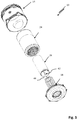
- Figs. 2 and 3 show exploded views of the fluid filter 10.
- the fluid filter 10 comprises a multi-part filter housing 12 with a filter container 14 extending along a longitudinal axis 16 of the filter housing 12 an which is only partially displayed in Fig. 1 .
- There is a housing lid 18 which serves to close an opening 20 of the filter container 14 provided at one end thereof.
- the housing lid 18 is detachably locked and secured against loosening on the filter container 14 which may, for instance, be realized by snap-fit, a mutual thread engagement of the housing lid 18 and the filter container 14 or by separate fastening means such as screws or the like.
- the filter housing 12, here the housing lid 18, is provided with a central support tube 22.
- the central support tube 22 is preferably molded-on the housing lid 18 such that the housing lid 18 and the support tube 22 can be manufactured as an one-piece injection-moulded part in a cost-efficient way.
- the central support tube 22 is thus an integral part of the filter housing 12 and is as such designed as a long-life part.
- the fluid filter 10 comprises a main or primary filter element 24 and an auxiliary or secondary filter element 26, which are each placed inside the filter housing 12 for filtering particulate matter, in particular dirt particles, contained in the fluid.
- Both the primary filter element 24 and the secondary filter element 26 are of a basically cylindrical design and comprise a filter medium 28 which is arranged in a circular fashion around a longitudinal axis 30, 32 of the respective filter element 24, 26.
- the filter medium 28 of the primary filter element may be a zig-zag-shaped pleated filter medium 28 to thereby increase the functional filter surface of the primary filter element 24.
- the filter medium 28 of the secondary filter element 26 preferably comprises or consists of a non-woven material.
- the filter medium of the secondary filter medium has a greater pore size than the filter medium 28 of the primary filter element 26.
- the fluid to be filtered sequentially flows through the primary and the secondary filter element 24, 26 in a radial direction from outside to inside.
- the secondary filter element is thus - in fluid view - arranged downstream with respect to the primary filter element 24.
- a clean fluid side of the fluid filter is denominated 34.
- the primary and the secondary filter element 24, 26 are each provided with an end disk 36 and which covers the filter medium 28 in an axial direction.
- the end disks 36 are formed of a resin material with the respective filter medium glued or welded to the end disk 36 or embedded in the material of the respective end disk 36.
- the primary filter element 24 has an integral central tube 38 of a perforated or grid-shaped design which supports the filter medium 28 of the primary filter element 24 in a radial direction on the inside thereof and which is best seen in Figs. 1 and 3 .
- Each of the filter elements 24, 26 has a central recess generally designated 40 in the drawing.
- the central recess 40 of the secondary filter element 26 is designed, structured and dimensioned such that the secondary filter element 26 may be directly threaded, that is slided, on the central support tube 22 of the filter housing 12.
- the central support tube 22 has a cross section which tapers towards a free end thereof.
- the central recess 40 of the primary filter element 24 is designed, structured and dimensioned such that the primary filter element 24 may be slided onto the secondary filter element 26 when mounting the primary filter element 24 inside the filter housing 12.
- the central support tube 22, the primary and the secondary filter element 24, 26 are arranged coaxially with respect to the longitudinal axis 16 of the filter housing 12.
- the secondary filter element is supported in a radial direction on an inside thereof by the central support tube 22 of the filter housing 12.
- the primary filter element 24 can clog resulting in an increase of pressure difference at the fluid filter 10.
- the primary filter element therefore, needs to be replaced at certain intervals to maintain a sufficient filtering function.
- the secondary filter element 26 preferably remains in its mounted position inside the filter housing 12 thereby serving as a back-up or safety filter element to prevent an ingress of dirt particles into the clean side 34 of the fluid filter 10 to protect an aggregate, in particular a combustion engine, fluidly connected thereto from potential damage associated therewith.
- the secondary filter element 26 can be made of a rather filigree construction with only very little material usage.
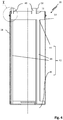
- Fig. 4 shows the secondary filter element 26 in a cropped view.
- the secondary filter element 26 has a minimalistic support structure 42, which is positioned in a radial direction on an inside of the filter medium.
- the support structure comprises a mounting ring 44, the end disk 36 and which are interconnected to one another by a plurality of axial struts 46 only. In other words, there are no further transverse struts, which interconnect the axial struts.
- the filter medium 28 is circumferentially attached, in particular glued, to the mounting ring 44 as well as to the end disc 36 of the support structure 42.
- the filter medium 28 of the secondary filter element 26 is sufficiently stabilized for mounting the secondary filter element 26 on the central support tube 22 of the fluid filter housing 12 ( Fig. 1 ) and maintaining a predetermined axial extension of the filter medium 28.
- snap-in tongues 48 provided on the mounting ring 44 of the support structure 42 which serve for a detachably connecting the secondary filter element 26 to the filter housing, preferably the central support tube 22 thereof.
- the snap-in tongues 48 are provided with first and second slanted surfaces 50, 52 such that the snap-in tongues may be easily slided into their locking position on filter housing 12 and be removed out of the said locking position ( Fig. 1 ) in an axial direction if necessary.
- a sealing abutment of the secondary filter element 26 against the filter housing 12 is desirable for preventing a bypass of contaminated fluid to the clean side ( Fig. 1 ) of the fluid filter 10.
- a sealing seat of the secondary filter element is realized in the embodiment shown in Figs 1 to 4 by a seal ring 54 which encompasses the filter medium 28 of the secondary filter element 26 in the region of tits first end portion 56 and which is in a sealing contact with a corresponding sealing surface provided by the filter housing, in particular the housing lid 18 thereof.
- the sealing ring 54 is preferably made of rubber or another rubber-elastically deformable material, in particular an elastomer, to ensure a sufficient sealing capacity.
- the seal ring 54 may be formed as a simple O-ring or, alternatively, may have a different cross-sectional shape.
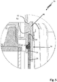
- Fig. 5 there is shown a detailed cutout of the fluid filter 10 which is designated "Z" in Fig. 1 .
- the snap-in tongues 48 each engage behind a ring shoulder 58 of the housing lid 18 which protrudes towards the longitudinal axis 16 of the filter housing 12 in a radially inside direction.
- the sealing ring 54 abuts against the sealing surface 60 of the housing lid 18 and the filter medium 18 in a radial direction.
- Fig. 6 shows a detailed view of a further embodiment of the fluid filter 10, where a sealing seat of the first end portion 65 of the secondary filter element 26 in the filter housing 12 is realized without a separate sealing element.
- the first end portion 56 of the secondary filter element 26 engages in a retaining structure 62 of the housing lid which is designed as a radial groove.
- the radial grove is designed dimensioned and structured such that the filter medium 28 is compressed in a radial direction between the radially inner mounting ring and the radially outer sealing surface of the filter housing 12. Due to the radial contact pressing of the filter medium 28 against the sealing surface 60, it is the filter medium 28 itself which acts as a sealing element.
- the groove-shaped retaining structure 62 tapers in an axial direction to facilitate insertion of the secondary filter element 26.
- the filter medium 28 and the mounting ring preferably have a radial thickness 64 in the unloaded state, that is in the unmounted state of the secondary filter element, which exceeds the minimal radial width 66 of the retaining structure 62 to allow for a compensation of typical manufacturing tolerances and to thereby provide a sufficient sealing effect.
Description
- The invention relates to a fluid filter for filtering fluid, in particular air, with a secondary filter element of lightweight construction and to a use of a secondary filter element.
-
DE 10 2015 004 965 A1 discloses a fluid filter which may be used for filtering air and which comprises a filter housing with an integral central support tube. The central support tube extends along a longitudinal axis of the filter housing within the filter housing. The known fluid filter has a primary filter element arranged inside the filter housing in an exchangeable manner, and an accessory or secondary filter element, which is positioned at least partially inside the primary filter element. Both filter elements are arranged coaxially with respect to the longitudinal axis of the filter housing such that the fluid to be filtered can sequentially flow through a filter medium of the primary filter element and subsequently the secondary filter element in a radial direction from outside to inside. The secondary filter element has a filter medium, which is directly supported in a radially inward direction by the central support tube. The filter medium, at one of the free end portions of the secondary filter element, directly engages in a groove-shaped retaining structure of the filter housing. The Secondary filter element has an end disc which is snap-fitted to the central support tube. When mounting of the secondary filter element to the retaining structure, the filter medium may be easily damaged such that there is a rsik of an ingress of dirt particles into the clean side of the fluid filter during replacement of the primary filter element. This may lead to damages to other components, such as a combustion engine of a motor vehicle or a fluid pump fluidly connected thereto. Further, the sealing abutment of the filter medium engaging against one of the groove flanks of the retaining structure is inevitably limited due to manufacturing tolerances of the secondary filter element and the filter housing. -
WO 02/49738 A1 - It is the object of the invention to provide a fluid filter with a secondary filter element and a secondary filter element that can be manufactured in a cost-efficient way and which may be mounted more safely to provide for a reliable sealing of the secondary filter element with respect to the filter housing.
- The fluid filter according to the invention has the features as given in claim 1. A secondary filter element according to the invention is given in claim 13. Preferred embodiments of the invention are subject of the dependent claims.
- In the fluid filter according to the invention, the secondary filter element of the fluid filter serves to protect the clean side of the filter element against an entry of undesirable particulate matter during maintenance work of the fluid filter, in particular when the primary filter element is replaced. Normally, dirt particles and other contaminants located inside the filter housing may become loosened and enter the clean side of the filter housing. When restarting the fluid filter, particulate matter would otherwise put a machine or component positioned downstream the fluid filter, e.g. a combustion engine of a car or truck, a high-pressure (injection) pump or the like, at risk for damage. The secondary filter element comprises a support structure with a mounting ring positioned at the first end portion of the secondary filter element and to which the filter medium is fixed in a non-detachably manner. A sealing between the first end portion of the secondary filter element and the filter housing is effected partially or solely by the filter medium of the secondary filter element. Due to the mounting ring, the filter medium is reinforced just at the end portion of the filter element, which is to sealingly abut against the filter housing. Mounting of the secondary filter element can be thereby be greatly facilitated and the risk of a damage of the filter medium is further reduced. As a result, the clean side of the fluid filter can be more reliably protected against an unwanted ingress of dirt particles.
- The support structure of the secondary filter element has an end disc. The mounting ring and the end disc are preferably connected to one another by axial struts. Thereby, the filter medium of the secondary filter element can be further reinforced such that the risk of an unwanted deformation or rupture of the filter medium is further reduced, in particular when mounting the filter element inside the filter housing. In this case, the filter medium may be formed of a highly flexible and rather low-cost material. Advantageously, there are no transverse bracings provided to minimize material usage and manufacturing costs of the secondary filter element.
- According to the invention, the mounting ring and the end disc can alternatively be interconnected by the filter medium of the second filter element only. By this, material usage can be further minimized. It is needless to say that the filter medium of the secondary filter element then needs to have rather stiff and (in an axial direction) self-supporting properties. This may be achieved by a textile finishing of the filter medium. For instance, the filter medium may be partially embedded in a resin material. Also, there may be metal or other fibers provided in the filter medium having a sufficient resistance to bending
- According to the invention, the filter medium of the secondary filter element may be glued, stitched and/or welded to the supporting structure.
- A sealing between the secondary filter element and the filter housing, there may be an elastically deformable, in particular elastomeric, sealing ring provided which encompasses the filter medium of the secondary filter element in the region of the mounting ring and which, preferably in a radial direction, sealingly abuts against a sealing surface of the filter housing. The sealing ring may be made of rubber or a suitable elastomer.
- The secondary filter element is snap-fitted to the filter housing, in particular the central support tube thereof, to ensure a proper seating of the secondary filter element within the filter housing. An unwanted dislodgement of the secondary filter element during use or during maintenance work can thereby be prevented.
- According to a preferred embodiment of the invention, the filter housing has a groove-shaped retaining structure with the first end portion of the filter element engaging into the said retaining structure. The groove-shaped retaining structure preferably tapers in an axial direction towards the groove base (bottom). This allows an easy mounting of the second filter element in a sealing position inside the groove. Further, the first end-portion of the secondary filter element can be held in said retaining structure in a radial press-fit. As to this, the filter medium and the mounting ring, in an unloaded state, that is unmounted state, preferably have a greater radial thickness than the minimal radial clear width of the groove-shaped retaining structure. This allows for a sufficient radial sealing between the first end portion of the secondary filter element and the filter housing.
- To further enhance the sealing capacity of the filter medium, the said filter medium may be doubled at the end portion of the secondary filter element. For this, the filter medium is preferably simply folded back with a free end section thereof. By this, more material of the filter medium can be compacted by a radial compression thereof and which ensures an improved sealing capacity of the filter medium. Clearly, this may also help compensate for dimensional tolerances of the supporting ring as well as the retaining structure.
- According to a further preferred embodiment of the invention, the filter medium of the secondary filter element comprises or consists of a fibrous, in particular a non-woven, material. These materials are available at low cost and with suitable mean pore sizes.
- The filter medium may have a larger mean pore size than the filter medium of the primary filter element as this is sufficient for protection of aggregates further downstream against damage. As to this, the filter medium of the second filter element is preferably designed, structured and adapted for filtering coarse particulate matter from the fluid, in particular with a diameter exceeding 0.1 millimeters.
- With respect to a cost-efficient and easy mounting of the secondary filter element inside the housing, the secondary filter element can be snap-fitted to the filter housing. By this, the secondary filter element may also be positioned in a predefined mounting position with respect to the filter housing as well as the main filter element. Further, the risk of an unfavorable dislodgment of the secondary filter element from its seal seat in the aforementioned groove-shaped retaining structure can be reliably prevented.
- According to the invention, the central support tube preferably has an outer diameter, which tapers in an axial direction towards the free end thereof. By this, the secondary filter element may be threaded more easily on the central support tube without damaging the support structure and/or filter medium of the secondary filter element.
- The filter housing may preferably comprise a filter bowl having a first opening and a lid for closing of the opening, wherein the central support tube is molded to or mounted, in particular snap-fitted, glued or welded, on the housing lid. This allows for an easy and cost-efficient replacement of the main filter element. Further, the support tube can be made of a thicker and a highly durable material which has a long life expectancy that exceeds that of the main filter element many times.
- The support structure of the secondary filter element is preferably made of a resin such as a thermoplast or a duroplast.
- The filter container may have a second opening positioned opposite to the first opening and a cover which is releasably attached to the filter container for closure of the second opening. This may further facilitate the replacement of the main filter element, in particular if the filter is mounted in a confined or difficult to reach space.
- The secondary filter element according to the invention, due to its lightweight and simple construction, is cost-efficient to manufacture and can be mounted easily and safely in the filter housing.
- Embodiments or the present invention will now be described, by way of example only, with reference to the accompanying drawings, in which:
- Fig. 1
- illustrates a fluid filter with a filter housing in which are seated a main and an auxiliary filter element, which serves as a safety element by which a potentially detrimental ingress of dirt particles onto the clean side of the fluid filter can be prevented during maintenance work;
- Fig. 2
- illustrates the fluid filter according to
Fig. 1 in a partially exploded view of it parts; - Fig. 3
- illustrates the fluid filter according to
Fig. 1 in a further partially exploded view of it parts; - Fig. 4
- shows a cross-sectional view of a secondary filter element of the fluid filter according to
Fig. 1 , - Fig. 5
- shows a detailed sectional view of the fluid filter according to
Fig. 1 ; - Fig. 6
- shows an alternative embodiment of a fluid filter in a partial sectional view.
- Referring to
Figures 1 to 3 , there is shown afluid filter 10 according to the invention and which may, for instance, be used as an air filter for an air intake of a combustion engine, in particular a utility vehicle such as a truck or a bulldozer or the like. InFig. 1 , thefluid filter 10 is shown in its partially assembled state, whereasFigs. 2 and3 show exploded views of thefluid filter 10. Thefluid filter 10 comprises amulti-part filter housing 12 with afilter container 14 extending along a longitudinal axis 16 of thefilter housing 12 an which is only partially displayed inFig. 1 . There is ahousing lid 18 which serves to close anopening 20 of thefilter container 14 provided at one end thereof. Thehousing lid 18 is detachably locked and secured against loosening on thefilter container 14 which may, for instance, be realized by snap-fit, a mutual thread engagement of thehousing lid 18 and thefilter container 14 or by separate fastening means such as screws or the like. Thefilter housing 12, here thehousing lid 18, is provided with acentral support tube 22. Thecentral support tube 22 is preferably molded-on thehousing lid 18 such that thehousing lid 18 and thesupport tube 22 can be manufactured as an one-piece injection-moulded part in a cost-efficient way. Thecentral support tube 22 is thus an integral part of thefilter housing 12 and is as such designed as a long-life part. - The
fluid filter 10 comprises a main orprimary filter element 24 and an auxiliary orsecondary filter element 26, which are each placed inside thefilter housing 12 for filtering particulate matter, in particular dirt particles, contained in the fluid. Both theprimary filter element 24 and thesecondary filter element 26 are of a basically cylindrical design and comprise afilter medium 28 which is arranged in a circular fashion around a longitudinal axis 30, 32 of therespective filter element filter medium 28 of the primary filter element may be a zig-zag-shapedpleated filter medium 28 to thereby increase the functional filter surface of theprimary filter element 24. Thefilter medium 28 of thesecondary filter element 26 preferably comprises or consists of a non-woven material. It needs to be noted, that the filter medium of the secondary filter medium has a greater pore size than thefilter medium 28 of theprimary filter element 26. The fluid to be filtered sequentially flows through the primary and thesecondary filter element primary filter element 24. A clean fluid side of the fluid filter is denominated 34. The primary and thesecondary filter element end disk 36 and which covers thefilter medium 28 in an axial direction. Theend disks 36 are formed of a resin material with the respective filter medium glued or welded to theend disk 36 or embedded in the material of therespective end disk 36. Theprimary filter element 24 has an integralcentral tube 38 of a perforated or grid-shaped design which supports thefilter medium 28 of theprimary filter element 24 in a radial direction on the inside thereof and which is best seen inFigs. 1 and3 . - Each of the
filter elements central recess 40 of thesecondary filter element 26 is designed, structured and dimensioned such that thesecondary filter element 26 may be directly threaded, that is slided, on thecentral support tube 22 of thefilter housing 12. Thecentral support tube 22 has a cross section which tapers towards a free end thereof. Thecentral recess 40 of theprimary filter element 24 is designed, structured and dimensioned such that theprimary filter element 24 may be slided onto thesecondary filter element 26 when mounting theprimary filter element 24 inside thefilter housing 12. In the assembled state of thefluid filter 10 as shown inFigure 1 , thecentral support tube 22, the primary and thesecondary filter element filter housing 12. The secondary filter element is supported in a radial direction on an inside thereof by thecentral support tube 22 of thefilter housing 12. - During use of the
fluid filter 10, theprimary filter element 24 can clog resulting in an increase of pressure difference at thefluid filter 10. The primary filter element, therefore, needs to be replaced at certain intervals to maintain a sufficient filtering function. When replacing theprimary filter element 24, thesecondary filter element 26 preferably remains in its mounted position inside thefilter housing 12 thereby serving as a back-up or safety filter element to prevent an ingress of dirt particles into theclean side 34 of thefluid filter 10 to protect an aggregate, in particular a combustion engine, fluidly connected thereto from potential damage associated therewith. - Due to the
central support tube 22 provided by the filter housing, thesecondary filter element 26 can be made of a rather filigree construction with only very little material usage. -
Fig. 4 shows thesecondary filter element 26 in a cropped view. Thesecondary filter element 26 has aminimalistic support structure 42, which is positioned in a radial direction on an inside of the filter medium. The support structure comprises a mountingring 44, theend disk 36 and which are interconnected to one another by a plurality ofaxial struts 46 only. In other words, there are no further transverse struts, which interconnect the axial struts. Thefilter medium 28 is circumferentially attached, in particular glued, to the mountingring 44 as well as to theend disc 36 of thesupport structure 42. By means of thesupport structure 42, thefilter medium 28 of thesecondary filter element 26 is sufficiently stabilized for mounting thesecondary filter element 26 on thecentral support tube 22 of the fluid filter housing 12 (Fig. 1 ) and maintaining a predetermined axial extension of thefilter medium 28. - There are snap-in
tongues 48 provided on the mountingring 44 of thesupport structure 42 which serve for a detachably connecting thesecondary filter element 26 to the filter housing, preferably thecentral support tube 22 thereof. The snap-intongues 48 are provided with first and secondslanted surfaces filter housing 12 and be removed out of the said locking position (Fig. 1 ) in an axial direction if necessary. A sealing abutment of thesecondary filter element 26 against thefilter housing 12 is desirable for preventing a bypass of contaminated fluid to the clean side (Fig. 1 ) of thefluid filter 10. A sealing seat of the secondary filter element is realized in the embodiment shown inFigs 1 to 4 by aseal ring 54 which encompasses thefilter medium 28 of thesecondary filter element 26 in the region of titsfirst end portion 56 and which is in a sealing contact with a corresponding sealing surface provided by the filter housing, in particular thehousing lid 18 thereof. The sealingring 54 is preferably made of rubber or another rubber-elastically deformable material, in particular an elastomer, to ensure a sufficient sealing capacity. Theseal ring 54 may be formed as a simple O-ring or, alternatively, may have a different cross-sectional shape. - In
Fig. 5 , there is shown a detailed cutout of thefluid filter 10 which is designated "Z" inFig. 1 . The snap-intongues 48 each engage behind aring shoulder 58 of thehousing lid 18 which protrudes towards the longitudinal axis 16 of thefilter housing 12 in a radially inside direction. The sealingring 54 abuts against the sealingsurface 60 of thehousing lid 18 and thefilter medium 18 in a radial direction. -
Fig. 6 shows a detailed view of a further embodiment of thefluid filter 10, where a sealing seat of the first end portion 65 of thesecondary filter element 26 in thefilter housing 12 is realized without a separate sealing element. Thefirst end portion 56 of thesecondary filter element 26 engages in a retainingstructure 62 of the housing lid which is designed as a radial groove. The radial grove is designed dimensioned and structured such that thefilter medium 28 is compressed in a radial direction between the radially inner mounting ring and the radially outer sealing surface of thefilter housing 12. Due to the radial contact pressing of thefilter medium 28 against the sealingsurface 60, it is thefilter medium 28 itself which acts as a sealing element. It needs to be noted, that the groove-shapedretaining structure 62 tapers in an axial direction to facilitate insertion of thesecondary filter element 26. Thefilter medium 28 and the mounting ring preferably have aradial thickness 64 in the unloaded state, that is in the unmounted state of the secondary filter element, which exceeds theminimal radial width 66 of the retainingstructure 62 to allow for a compensation of typical manufacturing tolerances and to thereby provide a sufficient sealing effect.
Claims (12)
- Fluid filter (10) for filtering a fluid, in particular air, comprising:- a filter housing (12) having an integral central support tube (22) which extends along a longitudinal axis (16) of the filter housing (12) within the filter housing (12);- a primary filter element (24) arranged inside the filter housing (12) in an exchangeable manner, and
a secondary filter element (26), which is positioned at least partially inside the main filter element (24) and which is supported in a radial direction on an inside thereof by the central support tube (22), wherein the secondary filter element (26) comprises a support structure (42) and a filter medium (28) arranged in a ring-shaped fashion around the support-structure (42), the support structure (42) comprising a mounting ring (44) positioned at a first end portion (56) of the secondary filter element (26) to which the filter medium (28) is fixed in a non-detachably manner and wherein a sealing between the first end portion (56) of the secondary filter element (26) and the filter housing (12) is effected partially or solely by the filter medium (28) of the secondary filter element (26), wherein the support structure of the secondary filter element (26) has an end disc (36), wherein the mounting ring (44) and the end disk (36) are connected to one another by axial struts (46), wherein the secondary filter element (26) is snap-fitted to the filter housing (12), in particular the central support tube (22) thereof, and wherein there are snap-in tongues (48) provided on the mounting ring (44) of the support structure (42) which serve for a detachable connecting the secondary filter element (26) to the filter housing. - Fluid filter according to claim 1, characterized in that there is an elastically deformable sealing ring (54) provided which encompasses said filter medium (28) of the secondary filter element (26) in the region of the mounting ring (44) and which, in a radial direction, sealingly abuts against a sealing surface (60) of the filter housing (12).
- Fluid filter according to any of the preceding claims, characterized in that the filter housing (12) has a groove-shaped retaining structure (62) with the first end portion (56) of the secondary filter element (26) engaging in said retaining structure (62).
- Fluid filter according to claim 3, characterized in that the groove-shaped retaining structure tapers in an axial direction such that the first end-portion (56) of the secondary filter element (26) is held in said retaining structure (62) in a radial press-fit.
- Fluid filter according to any of the preceding claims, characterized in that the filter medium (28), at the first end portion (56) of the secondary filter element (26), is doubled, in particular folded back.
- Fluid filter according to any one of the preceding claims, characterized in that the central support tube (22) of has a cross section which tapers in an axial direction towards a free end thereof.
- Fluid filter according to any of the preceding claims, characterized in that the filter medium (28) of the secondary filter element (26) comprises or is made of a fibrous, in particular non-woven, material.
- Fluid filter according to any of the preceding claims, characterized in that the filter medium (28) of the second filter element (26) has a larger mean pore size than the filter medium (28) of the primary filter element (24).
- Fluid filter according to claim 8, characterized in that the filter medium (28) of the secondary filter element (26) is designed, structured and adapted for filtering coarse particulate matter from the fluid, in particular with a diameter exceeding 0,1 millimeters.
- Fluid filter according to any of the preceding claims, characterized in that the filter housing comprises a filter container 14 having a first opening 20 and a lid for closing of the first opening 20, wherein the central support tube (22) is molded to or mounted, in particular snap-fitted, glued or welded, on the housing lid (18).
- Fluid filter according to claims 3 and 10, characterized in that the groove-shaped retaining structure (62) is provided on the housing lid (18).
- Use of a secondary filter element (26) in a fluid filter (10) according to any of the preceding claims,- wherein secondary filter element (26) is adapted to be positioned at least partially inside the main filter element (24) of the fluid filter (10) and in an installed position is supported in a radial direction on an inside thereof by the central support tube (22) of the fluid filter (10),- wherein the secondary filter element (26) comprises a support structure (42) and a filter medium (28) arranged in a ring-shaped fashion around the support-structure (42),- the support structure (42) comprising a mounting ring (44) positioned at a first end portion (56) of the secondary filter element (26) to which the filter medium (28) is fixed in a non-detachably manner and wherein a sealing between the first end portion (56) of the secondary filter element (26) and the filter housing (12) can be effected partially or solely by the filter medium (28) of the secondary filter element (26),- wherein the support structure of the secondary filter element (26) has an end disc (36),- wherein the mounting ring (44) and the end disk (36) are connected to one another by axial struts (46),- wherein the secondary filter element (26) can be snap-fitted to the filter housing (12) of the fluid filter (10), in particular the central support tube (22) thereof, and wherein there are snap-in tongues (48) provided on the mounting ring (44) of the support structure (42) which serve for a detachable connecting the secondary filter element (26) to the filter housing.
Priority Applications (3)
| Application Number | Priority Date | Filing Date | Title |
|---|---|---|---|
| EP18173518.4A EP3572138B1 (en) | 2018-05-22 | 2018-05-22 | Fluid filter with secondary filter element of lightweight construction |
| PCT/EP2019/062520 WO2019224079A1 (en) | 2018-05-22 | 2019-05-15 | Fluid filter with secondary filter element of lightweight construction |
| CN201980034125.7A CN112118899B (en) | 2018-05-22 | 2019-05-15 | Fluid filter with lightweight construction secondary filter element |
Applications Claiming Priority (1)
| Application Number | Priority Date | Filing Date | Title |
|---|---|---|---|
| EP18173518.4A EP3572138B1 (en) | 2018-05-22 | 2018-05-22 | Fluid filter with secondary filter element of lightweight construction |
Publications (2)
| Publication Number | Publication Date |
|---|---|
| EP3572138A1 EP3572138A1 (en) | 2019-11-27 |
| EP3572138B1 true EP3572138B1 (en) | 2021-12-22 |
Family
ID=62222481
Family Applications (1)
| Application Number | Title | Priority Date | Filing Date |
|---|---|---|---|
| EP18173518.4A Active EP3572138B1 (en) | 2018-05-22 | 2018-05-22 | Fluid filter with secondary filter element of lightweight construction |
Country Status (3)
| Country | Link |
|---|---|
| EP (1) | EP3572138B1 (en) |
| CN (1) | CN112118899B (en) |
| WO (1) | WO2019224079A1 (en) |
Families Citing this family (3)
| Publication number | Priority date | Publication date | Assignee | Title |
|---|---|---|---|---|
| DE102020131394A1 (en) * | 2020-11-26 | 2022-06-02 | Hengst Se | Primary filter for an air filter system |
| DE102021106524A1 (en) * | 2021-03-17 | 2022-09-22 | Mann+Hummel Gmbh | Filter element and filter system |
| EP4342564A1 (en) * | 2022-09-20 | 2024-03-27 | MANN+HUMMEL GmbH | Gas filter system |
Citations (10)
| Publication number | Priority date | Publication date | Assignee | Title |
|---|---|---|---|---|
| EP0752263A1 (en) * | 1995-07-07 | 1997-01-08 | Flair Corporation | Filter end cap attachment |
| DE19727369A1 (en) | 1997-06-27 | 1999-01-07 | Knecht Filterwerke Gmbh | Tubular filter element |
| WO2002049738A1 (en) | 2000-12-21 | 2002-06-27 | Filterwerk Mann + Hummel Gmbh | Filter element |
| WO2009014986A1 (en) | 2007-07-20 | 2009-01-29 | Donaldson Company, Inc. | Air cleaner arrangements with internal and external support for cartridge; components; and, methods |
| US7537631B2 (en) | 2002-10-28 | 2009-05-26 | Donaldson Company, Inc. | Filter cartridges; air cleaners; and methods |
| WO2012143793A1 (en) * | 2011-04-20 | 2012-10-26 | Ufi Innovation Center S.R.L. | A filter group |
| EP2086663B1 (en) | 2006-10-06 | 2014-05-14 | Donaldson Company, Inc. | Air cleaner |
| US20140144111A1 (en) | 2012-11-29 | 2014-05-29 | Donaldson Company Inc. | Filter cartridges; features and methods of assemlby; air cleaner assemblies; and, filter cartridge combinations |
| US9289712B2 (en) | 2007-11-15 | 2016-03-22 | Donaldson Company, Inc. | Air filter arrangements; assemblies; and, methods |
| DE102015004965A1 (en) | 2015-04-20 | 2016-10-20 | Mann + Hummel Gmbh | Secondary element for a filter system and filter system with a secondary element |
Family Cites Families (5)
| Publication number | Priority date | Publication date | Assignee | Title |
|---|---|---|---|---|
| AU2007211933A1 (en) * | 2007-08-24 | 2009-03-12 | Shanghai Kohler Electronics, Ltd. | Check valve and filter arrangement |
| CN201193574Y (en) * | 2008-04-25 | 2009-02-11 | 中国第一汽车集团公司 | Double stage air filter assembly structure |
| FR2993475B1 (en) * | 2012-07-19 | 2015-06-26 | Cummins Filtration Sarl | FILTERING ASSEMBLY COMPRISING A REMOVABLE FILTRATION CARTRIDGE |
| CN103785212B (en) * | 2014-01-26 | 2015-11-18 | 上虞市怡和金属机械制造有限公司 | A kind of dismountable type lubricating oil filter |
| US10682597B2 (en) * | 2016-04-14 | 2020-06-16 | Baldwin Filters, Inc. | Filter system |
-
2018
- 2018-05-22 EP EP18173518.4A patent/EP3572138B1/en active Active
-
2019
- 2019-05-15 WO PCT/EP2019/062520 patent/WO2019224079A1/en active Application Filing
- 2019-05-15 CN CN201980034125.7A patent/CN112118899B/en active Active
Patent Citations (11)
| Publication number | Priority date | Publication date | Assignee | Title |
|---|---|---|---|---|
| EP0752263A1 (en) * | 1995-07-07 | 1997-01-08 | Flair Corporation | Filter end cap attachment |
| DE19727369A1 (en) | 1997-06-27 | 1999-01-07 | Knecht Filterwerke Gmbh | Tubular filter element |
| WO2002049738A1 (en) | 2000-12-21 | 2002-06-27 | Filterwerk Mann + Hummel Gmbh | Filter element |
| US7537631B2 (en) | 2002-10-28 | 2009-05-26 | Donaldson Company, Inc. | Filter cartridges; air cleaners; and methods |
| EP2086663B1 (en) | 2006-10-06 | 2014-05-14 | Donaldson Company, Inc. | Air cleaner |
| WO2009014986A1 (en) | 2007-07-20 | 2009-01-29 | Donaldson Company, Inc. | Air cleaner arrangements with internal and external support for cartridge; components; and, methods |
| US20160279557A1 (en) | 2007-07-20 | 2016-09-29 | Donaldson Company, Inc. | Air cleaner arrangements; components; and methods |
| US9289712B2 (en) | 2007-11-15 | 2016-03-22 | Donaldson Company, Inc. | Air filter arrangements; assemblies; and, methods |
| WO2012143793A1 (en) * | 2011-04-20 | 2012-10-26 | Ufi Innovation Center S.R.L. | A filter group |
| US20140144111A1 (en) | 2012-11-29 | 2014-05-29 | Donaldson Company Inc. | Filter cartridges; features and methods of assemlby; air cleaner assemblies; and, filter cartridge combinations |
| DE102015004965A1 (en) | 2015-04-20 | 2016-10-20 | Mann + Hummel Gmbh | Secondary element for a filter system and filter system with a secondary element |
Also Published As
| Publication number | Publication date |
|---|---|
| CN112118899B (en) | 2024-02-02 |
| EP3572138A1 (en) | 2019-11-27 |
| WO2019224079A1 (en) | 2019-11-28 |
| CN112118899A (en) | 2020-12-22 |
Similar Documents
| Publication | Publication Date | Title |
|---|---|---|
| US10137390B2 (en) | Filter device, especially liquid filter | |
| US10408173B2 (en) | Filter element | |
| EP3572138B1 (en) | Fluid filter with secondary filter element of lightweight construction | |
| US7267706B2 (en) | Air filter | |
| EP2340883B1 (en) | Liquid filter arrangement | |
| US20170036155A1 (en) | Air filter system and air filter element for an air filter system | |
| US20080053884A1 (en) | Liquid filter element having keys | |
| CN101257956B (en) | Liquid filtering device | |
| US20060201865A1 (en) | Fuel filter with keys | |
| US20130270162A1 (en) | Liquid filter having a filter bypass valve and filter insert therefor | |
| CA2652904A1 (en) | Tri-flow filter element with venting | |
| US9314721B2 (en) | Filter system with seal | |
| US9914085B2 (en) | Filter element and filter system | |
| EP2744584A2 (en) | Hydraulic spin-on filter cartridge having base plate supporting radially directed seal | |
| US20160332095A1 (en) | Filtration System with Anti Drain Valve and Drain X-Seal | |
| US11554338B2 (en) | Filter elements, air cleaner assemblies, and methods of use and assembly | |
| US10486096B2 (en) | Axial flow air filter element | |
| US20090145825A1 (en) | Filter Arrangement for Liquids | |
| CN108698581B (en) | Air drying cylinder | |
| US20200261830A1 (en) | Filter | |
| CN105386902B (en) | Filter element and filter system | |
| US8361314B2 (en) | Single piece resilient combination bottom support and relief valve end seal element for fluid filters | |
| US8636901B2 (en) | Two part resilient combination bottom support and relief valve end seal assembly for fluid filters | |
| CN114746161A (en) | Liquid filter and volume compensation element for a liquid filter | |
| CN112584913A (en) | Filter device, filter element and adapter |
Legal Events
| Date | Code | Title | Description |
|---|---|---|---|
| PUAI | Public reference made under article 153(3) epc to a published international application that has entered the european phase |
Free format text: ORIGINAL CODE: 0009012 |
|
| STAA | Information on the status of an ep patent application or granted ep patent |
Free format text: STATUS: THE APPLICATION HAS BEEN PUBLISHED |
|
| AK | Designated contracting states |
Kind code of ref document: A1 Designated state(s): AL AT BE BG CH CY CZ DE DK EE ES FI FR GB GR HR HU IE IS IT LI LT LU LV MC MK MT NL NO PL PT RO RS SE SI SK SM TR |
|
| AX | Request for extension of the european patent |
Extension state: BA ME |
|
| STAA | Information on the status of an ep patent application or granted ep patent |
Free format text: STATUS: REQUEST FOR EXAMINATION WAS MADE |
|
| 17P | Request for examination filed |
Effective date: 20191211 |
|
| RBV | Designated contracting states (corrected) |
Designated state(s): AL AT BE BG CH CY CZ DE DK EE ES FI FR GB GR HR HU IE IS IT LI LT LU LV MC MK MT NL NO PL PT RO RS SE SI SK SM TR |
|
| STAA | Information on the status of an ep patent application or granted ep patent |
Free format text: STATUS: EXAMINATION IS IN PROGRESS |
|
| STAA | Information on the status of an ep patent application or granted ep patent |
Free format text: STATUS: EXAMINATION IS IN PROGRESS |
|
| 17Q | First examination report despatched |
Effective date: 20201014 |
|
| RAP3 | Party data changed (applicant data changed or rights of an application transferred) |
Owner name: MANN+HUMMEL GMBH |
|
| GRAP | Despatch of communication of intention to grant a patent |
Free format text: ORIGINAL CODE: EPIDOSNIGR1 |
|
| STAA | Information on the status of an ep patent application or granted ep patent |
Free format text: STATUS: GRANT OF PATENT IS INTENDED |
|
| INTG | Intention to grant announced |
Effective date: 20210727 |
|
| GRAS | Grant fee paid |
Free format text: ORIGINAL CODE: EPIDOSNIGR3 |
|
| GRAA | (expected) grant |
Free format text: ORIGINAL CODE: 0009210 |
|
| STAA | Information on the status of an ep patent application or granted ep patent |
Free format text: STATUS: THE PATENT HAS BEEN GRANTED |
|
| RIN1 | Information on inventor provided before grant (corrected) |
Inventor name: SCHULDT, JOACHIM Inventor name: VENKATRAMAN, SRIDHAR Inventor name: KUMARESAN, PRABHU Inventor name: SHARMA, MRIDUL Inventor name: NEEF, PASCAL Inventor name: FRITZSCHING, TORSTEN |
|
| AK | Designated contracting states |
Kind code of ref document: B1 Designated state(s): AL AT BE BG CH CY CZ DE DK EE ES FI FR GB GR HR HU IE IS IT LI LT LU LV MC MK MT NL NO PL PT RO RS SE SI SK SM TR |
|
| REG | Reference to a national code |
Ref country code: GB Ref legal event code: FG4D |
|
| REG | Reference to a national code |
Ref country code: CH Ref legal event code: EP |
|
| REG | Reference to a national code |
Ref country code: DE Ref legal event code: R096 Ref document number: 602018028414 Country of ref document: DE |
|
| REG | Reference to a national code |
Ref country code: AT Ref legal event code: REF Ref document number: 1456706 Country of ref document: AT Kind code of ref document: T Effective date: 20220115 |
|
| REG | Reference to a national code |
Ref country code: IE Ref legal event code: FG4D |
|
| REG | Reference to a national code |
Ref country code: LT Ref legal event code: MG9D |
|
| PG25 | Lapsed in a contracting state [announced via postgrant information from national office to epo] |
Ref country code: RS Free format text: LAPSE BECAUSE OF FAILURE TO SUBMIT A TRANSLATION OF THE DESCRIPTION OR TO PAY THE FEE WITHIN THE PRESCRIBED TIME-LIMIT Effective date: 20211222 Ref country code: LT Free format text: LAPSE BECAUSE OF FAILURE TO SUBMIT A TRANSLATION OF THE DESCRIPTION OR TO PAY THE FEE WITHIN THE PRESCRIBED TIME-LIMIT Effective date: 20211222 Ref country code: FI Free format text: LAPSE BECAUSE OF FAILURE TO SUBMIT A TRANSLATION OF THE DESCRIPTION OR TO PAY THE FEE WITHIN THE PRESCRIBED TIME-LIMIT Effective date: 20211222 Ref country code: BG Free format text: LAPSE BECAUSE OF FAILURE TO SUBMIT A TRANSLATION OF THE DESCRIPTION OR TO PAY THE FEE WITHIN THE PRESCRIBED TIME-LIMIT Effective date: 20220322 |
|
| REG | Reference to a national code |
Ref country code: NL Ref legal event code: MP Effective date: 20211222 |
|
| REG | Reference to a national code |
Ref country code: AT Ref legal event code: MK05 Ref document number: 1456706 Country of ref document: AT Kind code of ref document: T Effective date: 20211222 |
|
| PG25 | Lapsed in a contracting state [announced via postgrant information from national office to epo] |
Ref country code: SE Free format text: LAPSE BECAUSE OF FAILURE TO SUBMIT A TRANSLATION OF THE DESCRIPTION OR TO PAY THE FEE WITHIN THE PRESCRIBED TIME-LIMIT Effective date: 20211222 Ref country code: NO Free format text: LAPSE BECAUSE OF FAILURE TO SUBMIT A TRANSLATION OF THE DESCRIPTION OR TO PAY THE FEE WITHIN THE PRESCRIBED TIME-LIMIT Effective date: 20220322 Ref country code: LV Free format text: LAPSE BECAUSE OF FAILURE TO SUBMIT A TRANSLATION OF THE DESCRIPTION OR TO PAY THE FEE WITHIN THE PRESCRIBED TIME-LIMIT Effective date: 20211222 Ref country code: HR Free format text: LAPSE BECAUSE OF FAILURE TO SUBMIT A TRANSLATION OF THE DESCRIPTION OR TO PAY THE FEE WITHIN THE PRESCRIBED TIME-LIMIT Effective date: 20211222 Ref country code: GR Free format text: LAPSE BECAUSE OF FAILURE TO SUBMIT A TRANSLATION OF THE DESCRIPTION OR TO PAY THE FEE WITHIN THE PRESCRIBED TIME-LIMIT Effective date: 20220323 |
|
| PG25 | Lapsed in a contracting state [announced via postgrant information from national office to epo] |
Ref country code: NL Free format text: LAPSE BECAUSE OF FAILURE TO SUBMIT A TRANSLATION OF THE DESCRIPTION OR TO PAY THE FEE WITHIN THE PRESCRIBED TIME-LIMIT Effective date: 20211222 |
|
| PG25 | Lapsed in a contracting state [announced via postgrant information from national office to epo] |
Ref country code: SM Free format text: LAPSE BECAUSE OF FAILURE TO SUBMIT A TRANSLATION OF THE DESCRIPTION OR TO PAY THE FEE WITHIN THE PRESCRIBED TIME-LIMIT Effective date: 20211222 Ref country code: SK Free format text: LAPSE BECAUSE OF FAILURE TO SUBMIT A TRANSLATION OF THE DESCRIPTION OR TO PAY THE FEE WITHIN THE PRESCRIBED TIME-LIMIT Effective date: 20211222 Ref country code: RO Free format text: LAPSE BECAUSE OF FAILURE TO SUBMIT A TRANSLATION OF THE DESCRIPTION OR TO PAY THE FEE WITHIN THE PRESCRIBED TIME-LIMIT Effective date: 20211222 Ref country code: PT Free format text: LAPSE BECAUSE OF FAILURE TO SUBMIT A TRANSLATION OF THE DESCRIPTION OR TO PAY THE FEE WITHIN THE PRESCRIBED TIME-LIMIT Effective date: 20220422 Ref country code: ES Free format text: LAPSE BECAUSE OF FAILURE TO SUBMIT A TRANSLATION OF THE DESCRIPTION OR TO PAY THE FEE WITHIN THE PRESCRIBED TIME-LIMIT Effective date: 20211222 Ref country code: EE Free format text: LAPSE BECAUSE OF FAILURE TO SUBMIT A TRANSLATION OF THE DESCRIPTION OR TO PAY THE FEE WITHIN THE PRESCRIBED TIME-LIMIT Effective date: 20211222 Ref country code: CZ Free format text: LAPSE BECAUSE OF FAILURE TO SUBMIT A TRANSLATION OF THE DESCRIPTION OR TO PAY THE FEE WITHIN THE PRESCRIBED TIME-LIMIT Effective date: 20211222 |
|
| PG25 | Lapsed in a contracting state [announced via postgrant information from national office to epo] |
Ref country code: PL Free format text: LAPSE BECAUSE OF FAILURE TO SUBMIT A TRANSLATION OF THE DESCRIPTION OR TO PAY THE FEE WITHIN THE PRESCRIBED TIME-LIMIT Effective date: 20211222 Ref country code: AT Free format text: LAPSE BECAUSE OF FAILURE TO SUBMIT A TRANSLATION OF THE DESCRIPTION OR TO PAY THE FEE WITHIN THE PRESCRIBED TIME-LIMIT Effective date: 20211222 |
|
| REG | Reference to a national code |
Ref country code: DE Ref legal event code: R026 Ref document number: 602018028414 Country of ref document: DE |
|
| PG25 | Lapsed in a contracting state [announced via postgrant information from national office to epo] |
Ref country code: IS Free format text: LAPSE BECAUSE OF FAILURE TO SUBMIT A TRANSLATION OF THE DESCRIPTION OR TO PAY THE FEE WITHIN THE PRESCRIBED TIME-LIMIT Effective date: 20220422 |
|
| PLBI | Opposition filed |
Free format text: ORIGINAL CODE: 0009260 |
|
| PLAX | Notice of opposition and request to file observation + time limit sent |
Free format text: ORIGINAL CODE: EPIDOSNOBS2 |
|
| PG25 | Lapsed in a contracting state [announced via postgrant information from national office to epo] |
Ref country code: DK Free format text: LAPSE BECAUSE OF FAILURE TO SUBMIT A TRANSLATION OF THE DESCRIPTION OR TO PAY THE FEE WITHIN THE PRESCRIBED TIME-LIMIT Effective date: 20211222 Ref country code: AL Free format text: LAPSE BECAUSE OF FAILURE TO SUBMIT A TRANSLATION OF THE DESCRIPTION OR TO PAY THE FEE WITHIN THE PRESCRIBED TIME-LIMIT Effective date: 20211222 |
|
| 26 | Opposition filed |
Opponent name: DONALDSON COMPANY, INC. Effective date: 20220922 |
|
| PLAB | Opposition data, opponent's data or that of the opponent's representative modified |
Free format text: ORIGINAL CODE: 0009299OPPO |
|
| R26 | Opposition filed (corrected) |
Opponent name: DONALDSON COMPANY, INC. Effective date: 20220922 |
|
| REG | Reference to a national code |
Ref country code: CH Ref legal event code: PL |
|
| REG | Reference to a national code |
Ref country code: BE Ref legal event code: MM Effective date: 20220531 |
|
| GBPC | Gb: european patent ceased through non-payment of renewal fee |
Effective date: 20220522 |
|
| PG25 | Lapsed in a contracting state [announced via postgrant information from national office to epo] |
Ref country code: MC Free format text: LAPSE BECAUSE OF FAILURE TO SUBMIT A TRANSLATION OF THE DESCRIPTION OR TO PAY THE FEE WITHIN THE PRESCRIBED TIME-LIMIT Effective date: 20211222 Ref country code: LU Free format text: LAPSE BECAUSE OF NON-PAYMENT OF DUE FEES Effective date: 20220522 Ref country code: LI Free format text: LAPSE BECAUSE OF NON-PAYMENT OF DUE FEES Effective date: 20220531 Ref country code: CH Free format text: LAPSE BECAUSE OF NON-PAYMENT OF DUE FEES Effective date: 20220531 |
|
| PLBB | Reply of patent proprietor to notice(s) of opposition received |
Free format text: ORIGINAL CODE: EPIDOSNOBS3 |
|
| PG25 | Lapsed in a contracting state [announced via postgrant information from national office to epo] |
Ref country code: SI Free format text: LAPSE BECAUSE OF FAILURE TO SUBMIT A TRANSLATION OF THE DESCRIPTION OR TO PAY THE FEE WITHIN THE PRESCRIBED TIME-LIMIT Effective date: 20211222 |
|
| PG25 | Lapsed in a contracting state [announced via postgrant information from national office to epo] |
Ref country code: IE Free format text: LAPSE BECAUSE OF NON-PAYMENT OF DUE FEES Effective date: 20220522 Ref country code: FR Free format text: LAPSE BECAUSE OF NON-PAYMENT OF DUE FEES Effective date: 20220531 |
|
| PG25 | Lapsed in a contracting state [announced via postgrant information from national office to epo] |
Ref country code: IT Free format text: LAPSE BECAUSE OF FAILURE TO SUBMIT A TRANSLATION OF THE DESCRIPTION OR TO PAY THE FEE WITHIN THE PRESCRIBED TIME-LIMIT Effective date: 20211222 Ref country code: GB Free format text: LAPSE BECAUSE OF NON-PAYMENT OF DUE FEES Effective date: 20220522 Ref country code: BE Free format text: LAPSE BECAUSE OF NON-PAYMENT OF DUE FEES Effective date: 20220531 |
|
| P01 | Opt-out of the competence of the unified patent court (upc) registered |
Effective date: 20230530 |
|
| PGFP | Annual fee paid to national office [announced via postgrant information from national office to epo] |
Ref country code: DE Payment date: 20220620 Year of fee payment: 6 |
|
| PLCK | Communication despatched that opposition was rejected |
Free format text: ORIGINAL CODE: EPIDOSNREJ1 |
|
| PG25 | Lapsed in a contracting state [announced via postgrant information from national office to epo] |
Ref country code: HU Free format text: LAPSE BECAUSE OF FAILURE TO SUBMIT A TRANSLATION OF THE DESCRIPTION OR TO PAY THE FEE WITHIN THE PRESCRIBED TIME-LIMIT; INVALID AB INITIO Effective date: 20180522 |