EP2229028B1 - Vorrichtung zur vermessung biologischer proben und system zur vermessung biologischer proben damit - Google Patents
Vorrichtung zur vermessung biologischer proben und system zur vermessung biologischer proben damit Download PDFInfo
- Publication number
- EP2229028B1 EP2229028B1 EP08863718.6A EP08863718A EP2229028B1 EP 2229028 B1 EP2229028 B1 EP 2229028B1 EP 08863718 A EP08863718 A EP 08863718A EP 2229028 B1 EP2229028 B1 EP 2229028B1
- Authority
- EP
- European Patent Office
- Prior art keywords
- transmission power
- history information
- power
- transmitter
- biological sample
- Prior art date
- Legal status (The legal status is an assumption and is not a legal conclusion. Google has not performed a legal analysis and makes no representation as to the accuracy of the status listed.)
- Not-in-force
Links
Images


Classifications
-
- A—HUMAN NECESSITIES
- A61—MEDICAL OR VETERINARY SCIENCE; HYGIENE
- A61B—DIAGNOSIS; SURGERY; IDENTIFICATION
- A61B5/00—Measuring for diagnostic purposes; Identification of persons
- A61B5/0002—Remote monitoring of patients using telemetry, e.g. transmission of vital signals via a communication network
-
- G—PHYSICS
- G01—MEASURING; TESTING
- G01N—INVESTIGATING OR ANALYSING MATERIALS BY DETERMINING THEIR CHEMICAL OR PHYSICAL PROPERTIES
- G01N33/00—Investigating or analysing materials by specific methods not covered by groups G01N1/00 - G01N31/00
- G01N33/48—Biological material, e.g. blood, urine; Haemocytometers
- G01N33/483—Physical analysis of biological material
- G01N33/487—Physical analysis of biological material of liquid biological material
- G01N33/48785—Electrical and electronic details of measuring devices for physical analysis of liquid biological material not specific to a particular test method, e.g. user interface or power supply
- G01N33/48792—Data management, e.g. communication with processing unit
-
- A—HUMAN NECESSITIES
- A61—MEDICAL OR VETERINARY SCIENCE; HYGIENE
- A61B—DIAGNOSIS; SURGERY; IDENTIFICATION
- A61B2560/00—Constructional details of operational features of apparatus; Accessories for medical measuring apparatus
- A61B2560/02—Operational features
- A61B2560/0204—Operational features of power management
- A61B2560/0209—Operational features of power management adapted for power saving
-
- A—HUMAN NECESSITIES
- A61—MEDICAL OR VETERINARY SCIENCE; HYGIENE
- A61B—DIAGNOSIS; SURGERY; IDENTIFICATION
- A61B5/00—Measuring for diagnostic purposes; Identification of persons
- A61B5/145—Measuring characteristics of blood in vivo, e.g. gas concentration or pH-value ; Measuring characteristics of body fluids or tissues, e.g. interstitial fluid or cerebral tissue
- A61B5/14532—Measuring characteristics of blood in vivo, e.g. gas concentration or pH-value ; Measuring characteristics of body fluids or tissues, e.g. interstitial fluid or cerebral tissue for measuring glucose, e.g. by tissue impedance measurement
-
- G—PHYSICS
- G16—INFORMATION AND COMMUNICATION TECHNOLOGY [ICT] SPECIALLY ADAPTED FOR SPECIFIC APPLICATION FIELDS
- G16H—HEALTHCARE INFORMATICS, i.e. INFORMATION AND COMMUNICATION TECHNOLOGY [ICT] SPECIALLY ADAPTED FOR THE HANDLING OR PROCESSING OF MEDICAL OR HEALTHCARE DATA
- G16H10/00—ICT specially adapted for the handling or processing of patient-related medical or healthcare data
- G16H10/40—ICT specially adapted for the handling or processing of patient-related medical or healthcare data for data related to laboratory analysis, e.g. patient specimen analysis
-
- G—PHYSICS
- G16—INFORMATION AND COMMUNICATION TECHNOLOGY [ICT] SPECIALLY ADAPTED FOR SPECIFIC APPLICATION FIELDS
- G16H—HEALTHCARE INFORMATICS, i.e. INFORMATION AND COMMUNICATION TECHNOLOGY [ICT] SPECIALLY ADAPTED FOR THE HANDLING OR PROCESSING OF MEDICAL OR HEALTHCARE DATA
- G16H40/00—ICT specially adapted for the management or administration of healthcare resources or facilities; ICT specially adapted for the management or operation of medical equipment or devices
- G16H40/60—ICT specially adapted for the management or administration of healthcare resources or facilities; ICT specially adapted for the management or operation of medical equipment or devices for the operation of medical equipment or devices
- G16H40/67—ICT specially adapted for the management or administration of healthcare resources or facilities; ICT specially adapted for the management or operation of medical equipment or devices for the operation of medical equipment or devices for remote operation
Definitions
- the present invention relates to a biological sample measurement apparatus, and more specifically, relates to a biological sample measurement apparatus having a wireless communication function, and to a biological sample measurement system equipped with this.
- wireless portable terminal devices have been disclosed in which the transmission power is optimally adjusted.
- a reception power RX that is the power of the signal received by the communication partner device in a communication state is compared with a reference power RXref that is a reference for the reception power, and if RX is not greater than RXref, the transmission power is returned to its default value, but if RX is greater than RXref, the transmission power is reduced before data is transmitted.
- the transmission power is returned to its original value, but if the error rate has not decreased, the transmission power is controlled by maintaining the current transmission power.
- Patent Citation 1 Japanese Laid-Open Patent Application H10-285109 (disclosed on 23 Oct. 1998)
- the Japanese patent application JP2002 251461 is concerned with a data processing device which effectively utilizes data measured by plural kinds of measuring instruments.
- this patent application suggests a portable terminal device which collects test data of one subject by plural kinds of measuring instruments such a as blood sugar measuring instrument, a sphygmomanometer and transmits these plural kinds of test data to the data processing device in an order predetermined for a particular receiver.
- the Japanese patent application JP2007 013538 is directed towards a communication method for effectively carrying out communication with a simple structure.
- the method includes a storage step for storing history of transmission situations when transmitting data to the communication equipment on the reception side as transmission history information; a communication path situations decision step for deciding the communication situations with the communication equipment on the reception side on the basis of the transmission history information; and a transmission power control step for controlling the transmission power in transmitting data to the communication equipment on the reception side on the basis of a decision result of the communication path situations decision part.
- JP 2002-251461 discloses a measurement device suitable to collect and process biological data, e.g., to determine the level of metabolites or to determine further parameters like blood pressure, pulse rate or body temperature and the like.
- JP 2007-013538 discloses the use of transmission history information as basis for controlling transmission power as part of a data communication method capable of performing efficient communication.
- the transmission power is optimized on the basis of the error rate, optimization of the transmission power cannot be achieved until a specific volume of data is sent or received. Therefore, the transmission power cannot be optimized if an extremely small quantity of data is sent wirelessly, such as blood glucose level data measured with a wireless blood glucose meter, for example.
- the biological sample measurement apparatus pertaining to the first invention is a biological sample measurement apparatus for communicating wirelessly with external device, comprising a biological data measurement component, a transmitter, a receiver, a storage component, and a transmission power determiner.
- the biological data measurement component measures biological data.
- the transmitter transmits the biological data measured by the biological data measurement component.
- the receiver receives an acknowledge signal that is returned when the external device has properly received the biological data transmitted by the transmitter.
- the storage component stores history information whether or not the acknowledge signal was received and a transmission power when the transmitter has transmitted the biological data.
- the transmission power determiner extracts history information from the history information stored in the storage component and determines transmission power of the transmitter for further biological data, on the basis of the extracted history information for previously transmitted biological data from the biological sample measurement apparatus.
- the transmission power determiner determines the transmission power of the transmitter before the transmitter transmits the further biological data.
- the transmission power determiner extracts the history information in conformity with an extraction condition of a transmission determination rule such that the extracted history information includes transmission power and a presence or an absence of the received acknowledge signal for the previously transmitted biological data measured under a specific environment in which the biological measurement apparatus is used.
- the transmission power determiner determines the transmission power when the transmitter transmits on the basis of the history information stored in the storage component, or history information extracted according to a transmission power determination rule that sets forth extraction conditions.
- a portable terminal (a type of external device) has properly received a blood glucose level sent by a wireless blood glucose meter (a type of biological sample measurement apparatus)
- the portable terminal transmits the acknowledge signal to the wireless blood glucose meter.
- the wireless blood glucose meter stores as a piece of history information the transmission power when the blood glucose level was sent and whether or not the acknowledge signal was received for that transmission, and determines the transmission power during transmission on the basis of this history information.
- the optimization of transmission power in a wireless terminal device was performed on the basis of the error rate during transmission and reception.
- the transmission power cannot be optimized unless a specific volume of data is transmitted or received, so the transmission power cannot be optimized if an extremely small quantity of data is sent wirelessly, such as a blood glucose level measured with a wireless blood glucose meter, for example.
- the transmission power when the transmitter transmits biological data and whether or not an acknowledge signal has been received for that transmission are stored as history information, and the transmission power during transmission by the transmitter is determined on the basis of this history information. Also, the transmission power may be determined on the basis of history information extracted according to a transmission power determination rule that sets forth the specific extraction conditions.
- the transmission power of the transmitter transmission power in a piece of history information indicating that the biological data sent by the transmitter has been properly received. For example, even though a specific volume of data has not been sent or received between the wireless blood glucose meter and the portable terminal, it is possible to determine as the transmission power of the transmitter transmission power in a piece of history information for which the acknowledge signal has been received, that is, a piece of history information at which intercommunication was possible between the wireless blood glucose meter and the portable terminal. Also, for example, if there are a plurality of pieces of history information at which intercommunication was possible between the wireless blood glucose meter and the portable terminal, the lowest transmission power in the plurality of pieces of history information can be determined as the transmission power of the transmitter.
- the biological sample measurement apparatus pertaining to the second invention is the biological sample measurement apparatus pertaining to the first invention, wherein the transmission power determiner extracts a specific number of pieces of the history information according to the transmission power determination rule, and determines the transmission power of the transmitter so that the transmission power of the transmitter is lower than the transmission power stored as the history information, when the extracted history information includes at least a specific number of pieces of the history information for which the acknowledge signal has been received.
- the transmission power determiner decides that the output of the transmission power is sufficient in transmission by the transmitter, and the transmission power is lowered by a specific value.
- the transmission power determination rule referred to here means the conditions for extracting the history information, such as a condition that the extraction will be performed in the order of newest to oldest, or a condition that the extraction will be performed on the same day of the week or at the same time of day as when the biological data is measured.
- the transmission power in transmission by the transmitter is preferably kept as low as possible, while still allowing communication, in order to reduce power consumption.
- the transmission power of the transmitter can be lowered while still allowing communication, so a power saving can be obtained.
- the biological sample measurement apparatus pertaining to the third invention is the biological sample measurement apparatus pertaining to the first invention, wherein the transmission power determiner extracts a specific number of pieces of the history information according to a transmission power determination rule, and determines the transmission power of the transmitter so that the transmission power of the transmitter is higher than the transmission power stored as the history information, when the extracted history information does not include at least a specific number of pieces of the history information for which the acknowledge signal has been received.
- the transmission power determiner decides that the output of the transmission power is insufficient in transmission by the transmitter, and the transmission power is raised by a specific value.
- the transmission power can be determined more optimally so that the biological data sent by the transmitter can be received properly.
- the transmission power can be determined more optimally so that the data sent from the wireless blood glucose meter can be properly received by the portable terminal.
- the biological sample measurement apparatus pertaining to the fourth invention is the biological sample measurement apparatus pertaining to any of the first to third inventions, further comprising a noise power measurement component for measuring noise power just before the transmitter transmits, wherein the storage component further stores as the history information the noise power measured by the noise power measurement component.
- a noise power measurement component that measures the noise power just before transmission by the transmitter is further provided in order to take into account the noise power in determining the transmission power in transmission by the transmitter.
- the storage component stores the noise power measured by the noise power measurement component as history information along with whether or not there is an acknowledge signal and the transmission power when the transmitter transmits biological data.
- noise power generally has an adverse effect on communication between wireless terminal devices.
- the biological sample measurement apparatus pertaining to the fifth invention is the biological sample measurement apparatus pertaining to the fourth invention, wherein the transmission power determiner extracts the history information for which the acknowledge signal has been received according to the transmission power determination rule, and determines the transmission power of the transmitter on the basis of the noise power measured by the noise power measurement component, so that a ratio of the measured noise power to the transmission power of the transmitter is the same as a ratio of the noise power to the transmission power in the extracted history information.
- the ratio of noise power to transmission power which is the inverse of so-called S/N ratio, is calculated from the history information indicating that the biological data sent by the transmitter has been properly received. Since the noise power during transmission is a known condition by noise power measurement component, the transmission power during transmission by the transmitter is determined so as to obtain the inverse of the above-mentioned S/N ratio on the basis of this.
- the biological sample measurement apparatus pertaining to the sixth invention is the biological sample measurement apparatus pertaining to the fourth invention, wherein the transmission power determiner extracts a specific number of pieces of the history information according to the transmission power determination rule, and determines the transmission power of the transmitter on the basis of the noise power measured by the noise power measurement component, so that a ratio of the measured noise power to the transmission power of the transmitter is greater than the ratio of the noise power to the transmission power in the history information, when the extracted history information includes at least a specific number of pieces of the history information for which the acknowledge signal has been received.
- the transmission power determiner determines that the transmission power is sufficient in transmission by the transmitter, and the S/N ratio is lowered by a specific value.
- the transmission power in transmission by the transmitter is preferably kept as low as possible, while still allowing communication, in order to reduce power consumption.
- the transmission power of the transmitter can be lowered while still allowing communication, so a power saving can be obtained.
- the biological sample measurement apparatus pertaining to the seventh invention is the biological sample measurement apparatus pertaining to the fourth invention, wherein the transmission power determiner extracts a specific number of pieces of the history information according to a transmission power determination rule, and determines the transmission power of the transmitter with respect to the noise power measured by the noise power measurement component, so that a ratio of the measured noise power to the transmission power of the transmitter is less than the ratio of the noise power to the transmission power in the history information, when the extracted history information does not include at least a specific number of pieces of the history information for which the acknowledge signal has been received.
- the transmission power determiner determines that the transmission power is insufficient in transmission by the transmitter, and the S/N ratio is raised by a specific value.
- the transmission power can be determined more optimally so that the biological data sent by the transmitter can be properly received.
- the transmission power can be determined more optimally so that the data sent from the wireless blood glucose meter can be properly received by the portable terminal.
- the biological sample measurement apparatus pertaining to the eighth invention is a biological sample measurement apparatus for communicating wirelessly with an external device, comprising a biological data measurement component, a transmitter, a receiver, a storage component, and a transmission power determiner.
- the biological data measurement component measures the biological data.
- the transmitter transmits the biological data measured by the biological data measurement component.
- the receiver receives an acknowledge signal that is returned when the external device has properly received the biological data transmitted by the transmitter.
- the storage component stores a reference reception power that is the optimal reception power when the external device receives the biological data, and the history information that includes whether or not an acknowledge signal was received and transmission power when the transmitter transmitted the biological data, and reception power when the external device has received the biological data.
- the transmission power determiner extracts history information from the history information stored in the storage component, and determines transmission power of the transmitter for further biological data, on the basis of the extracted history information for previously transmitted biological data from the biological sample measurement apparatus.
- the transmission power determiner determines the transmission power of the transmitter before the transmitter transmits the further biological data.
- the transmission power determiner extracts the history information in conformity with an extraction condition of a transmission determination rule such that the extracted history information includes reference reception power, transmission power and a presence or an absence of a received acknowledgement signal for the previously transmitted biological data measured under a specific environment in which the biological sample measurement apparatus is used.
- the transmission power determiner determines the transmission power in transmission by the transmitter on the basis of the history information and reference reception power stored in the storage component, or the history information extracted according to a transmission power determination rule that sets forth extraction conditions and the reference reception power.
- the “reception power when an external device received the biological data” here can be stored in the storage component by replying simultaneously with the acknowledge signal returned by the external device, and receiving the acknowledge signal.
- the “reference reception power” defines the reception power for an external device to properly receive biological data, that is, the optimal reception power in receiving biological data. If we ignore the external environment and so forth, an external device can generally receive biological data properly if the transmitter sends at transmission power corresponding to the reference reception power.
- the optimization of transmission power in a wireless terminal device was performed on the basis of the error rate during transmission and reception.
- the transmission power cannot be optimized unless a specific volume of data is transmitted or received, so the transmission power cannot be optimized if an extremely small quantity of data is sent wirelessly, such as a blood glucose level measured with a wireless blood glucose meter, for example.
- a reference reception power that is the optimal reception power for the external device, and history information including the transmission power when the transmitter transmitted biological data, whether or not an acknowledge signal was received for this transmission, and the reception power when an external device received the biological data are stored, and the transmission power in transmission by the transmitter is determined on the basis of this history information and reference reception power.
- the transmission power may be determined on the basis of the history information extracted according to a transmission power determination rule that sets forth specific extraction conditions, and reference reception power.
- the transmission power in transmission by the transmitter can be determined by comparing the reference reception power stored in the storage component with, for example, the most recent history information for which an acknowledge signal has been received. Accordingly, for example, even though a specific volume of data has not been sent or received between the wireless blood glucose meter and the portable terminal, it is possible to determine the transmission power in transmission by the transmitter on the basis of the history information stored in the storage component.
- the biological sample measurement apparatus pertaining to the ninth invention is the biological sample measurement apparatus pertaining to the eighth invention, wherein the transmission power determiner extracts one piece of the history information according to the transmission power determination rule, and compares the reception power in the extracted history information with the reference reception power, and if the reception power is higher than the reference reception power, the transmission power when the transmitter transmits is determined so as to be lower than the transmission power stored as the extracted history information, and if the reception power is lower than the reference reception power, the transmission power when the transmitter transmits is determined so as to be higher than the transmission power stored as the extracted history information.
- the most recent history information is extracted, for example.
- the reference reception power and the reception power included in the extracted history information are compared, and the transmission power in transmission by the transmitter is determined on the basis of the comparison result.
- the transmission power at which the transmitter transmits and the reception power at which the external device receives may differ with the external environment and so forth.
- the external environment here also encompasses the remaining battery charge of the external device, and situations such as when the external device has been replaced.
- the transmission power in transmission by the transmitter can be determined on the basis of the reception power when the external device on the reception side actually received biological data.
- the transmission power can be properly optimized even when the transmission power in transmission by the transmitter and the reception power when received by the external device are different due to the external environment or the like.
- the biological sample measurement apparatus pertaining to the tenth invention is the biological sample measurement apparatus pertaining to the eighth or ninth invention, wherein the transmission power determiner extracts a specific number of pieces of the history information according to the transmission power determination rule, and if the extracted history information includes at least a specific number of pieces of the history information for which the acknowledge signal has been received, the reference reception power is set lower than the value stored in the storage component.
- the transmission power determiner decides that the output of reception power is sufficient in reception by an external device, and lowers the reference reception power by a specific value.
- the transmission power determination rule referred to here means the conditions for extracting history information, such as a condition that the extraction will be performed in the order of newest to oldest, or a condition that the extraction will be performed on the same day of the week or at the same time of day as when the biological data is measured.
- the transmission power in transmission by the transmitter is preferably kept as low as possible, while still allowing communication, in order to reduce power consumption. That is, since the transmission power in transmission by the transmitter is determined on the basis of the reference reception power, the transmission power in transmission by the transmitter can be lowered by lowering the reference reception power.
- the biological sample measurement apparatus pertaining to the eleventh invention is the biological sample measurement apparatus pertaining to the eighth or ninth invention, wherein the transmission power determiner extracts a specific number of pieces of the history information according to the transmission power determination rule, and if the extracted history information does not include at least a specific number of pieces of the history information for which the acknowledge signal has been received, the reference reception power is set higher than the value stored in the storage component.
- the transmission power determiner decides that the output of reception power is insufficient in reception by an external device, and raises the reference reception power by a specific value.
- the transmission power in transmission by the transmitter is determined on the basis of the reference reception power, the transmission power in transmission by the transmitter can be raised by raising the reference reception power.
- the transmission power can be optimally determined so that the biological data sent by the transmitter can be properly received.
- the reference reception power can be set optimally so that the data sent from the wireless blood glucose meter can be properly received by the portable terminal.
- the biological sample measurement apparatus pertaining to the twelfth invention is the biological sample measurement apparatus pertaining to any of the first to eleventh inventions, wherein the transmission power determination rule is set up so as to extract the history information in the order of newest to oldest.
- the transmission power determination rule is set up so that the history information stored in the storage component is extracted in the order of newest to oldest.
- the biological sample measurement apparatus pertaining to the thirteenth invention is the biological sample measurement apparatus pertaining to any of the first to twelfth inventions, wherein the transmission power determination rule is set up so as to extract, from among the history information stored in the storage component, the history information for the same day of the week as when the history information is extracted by the transmission power determiner.
- the optimal transmission power to be transmitted by the transmitter will vary with the environment in which the biological sample measurement apparatus is used. It is considered most likely that on a given day of the week, the user will generally use the biological sample measurement apparatus in the same place, that is, in the same environment. Accordingly, it is considered most likely that history information for which there is an acknowledge signal corresponding to the same conditions (same day of the week) as when the history information is extracted, that is, when a measurement is made with the biological sample measurement apparatus, will afford the optimal transmission power.
- the environment in which the biological sample measurement apparatus is used can be taken into account, so the transmission power can be determined more optimally.
- the biological sample measurement apparatus pertaining to the fourteenth invention is the biological sample measurement apparatus pertaining to any of the first to thirteenth inventions, wherein the transmission power determination rule is set up so as to extract the history information of the same time period as when the history information is extracted by the transmission power determiner.
- the transmission power determination rule is set up so that, of the history information stored in the storage component, the history information of the same time period as when the history information was extracted by the transmission power determiner will be extracted.
- the environment in which the biological sample measurement apparatus is used can be taken into account, so the transmission power can be determined more optimally.
- the biological sample measurement apparatus pertaining to the fifteenth invention is the biological sample measurement apparatus pertaining to any of the first to fourteenth inventions, wherein the transmission power determiner determines the maximum transmission power which the transmitter is able to output if the biological data measured by the biological data measurement component is not a value within a specific range.
- the biological data measured by the biological data measurement component is higher than a specific value
- the biological data is sent at the maximum transmission power at which the transmitter is able to output.
- the biological data measured by the biological data measurement component is higher than a specific value
- the biological data is sent at the maximum transmission power at which the transmitter is able to output to the portable terminal.
- the probability that the biological data sent by the transmitter cannot be received due to some kind of problem For instance, if the blood glucose level measured by a wireless blood glucose meter is higher than a specific value, that is, if there is an urgent need for treatment by a physician or the like, it is possible to lower the probability of a situation in which the portable terminal cannot receive the blood glucose level.
- the biological sample measurement apparatus pertaining to the sixteenth invention is the biological sample measurement apparatus pertaining to any of the first to fifteenth inventions, further comprising an interface having a display component for displaying the biological data measured by the biological data measurement component, an operating setting component for allowing the user to make various operating settings, and an alarm sound output component for outputting an alarm sound, wherein, if the biological data measured by the biological data measurement component is lower than a specific value, an alarm sound is outputted from the alarm sound output component, and an emergency status is displayed on the display component.
- the alarm sound output component outputs an alarm sound, and some kind of message is displayed on the display component.
- a blood glucose level that is below a specific value represents a dangerous situation to a diabetes patient, and in some cases can lead to impaired consciousness.
- the alarm sound output component outputs an alarm sound, and how to deal with hypoglycemia or another such message is displayed on the display component.
- the user himself or a person close to the user of the biological sample measurement apparatus can be alerted that the user is in a dangerous situation. Also, even if the person using the wireless blood glucose meter should lose consciousness, a person nearby will be able to take the appropriate measures by looking at the message displayed on the display component.
- the biological sample measurement apparatus pertaining to the seventeenth invention is the biological sample measurement apparatus pertaining to the sixteenth invention, wherein the emergency status is a telephone number.
- the biological sample measurement apparatus pertaining to the eighteenth invention is the biological sample measurement apparatus pertaining to the sixteenth or seventeenth invention, wherein the emergency status is a method for treating hypoglycemia.
- the biological sample measurement apparatus pertaining to the nineteenth invention is the biological sample measurement apparatus pertaining to any of the first to eighteenth inventions, wherein the biological data measurement component is a wireless blood glucose meter constituted so as to measure a blood glucose level.
- the transmission power in the history information stored in the storage component with which an acknowledge signal has been received can be determined as the transmission power in transmission by the transmitter.
- transmission power can be optimized regardless of the volume of data being transmitted.
- the biological sample measurement system pertaining to the twentieth invention comprises a biological sample measurement apparatus and an external device.
- the biological sample measurement apparatus is the biological sample measurement apparatus pertaining to any of the eighth to eleventh inventions.
- the external device has an external receiver, an error detector, an external transmitter, a reception power determiner, and a transmission power selector.
- the external receiver receives biological data transmitted from the biological sample measurement apparatus.
- the error detector determines whether or not the external receiver has properly received the biological data.
- the external transmitter transmits an acknowledge signal to the biological sample measurement apparatus when the error detector has determined that the biological data has been properly received.
- the reception power determiner measures the reception power when the external receiver has received the biological data, and compares this with a specific value.
- the transmission power selector selects the transmission power of the external transmitter on the basis of the determination result of the reception power determiner.
- the biological sample measurement system pertaining to the twenty-first invention is the biological sample measurement system pertaining to the twentieth invention, wherein the transmission power selector selects the maximum power as the transmission power in the external transmitter when the reception power determiner has determined that the reception power when the biological data has been received by the external receiver is lower than the specific value.
- the biological sample measurement apparatus pertaining to the present invention and the biological sample measurement system equipped with this apparatus, make it possible to optimize the transmission power regardless of the volume of data being sent.
- a wireless blood glucose meter (biological sample measurement apparatus) 2 pertaining to an embodiment of the present invention will now be described through reference to FIGS. 1 to 12 .
- a blood glucose level (biological data) is measured about eight times a day with the wireless blood glucose meter 2.
- the user of the wireless blood glucose meter 2 connects an electrochemical, disposable biosensor 1 to the wireless blood glucose meter 2, and puts a spot of blood on the biosensor 1.
- the wireless blood glucose meter 2 detects the blood glucose level from the connected biosensor 1, and sends the detected blood glucose level data to a portable terminal (external device) 3 used to load measurement data about a patient by a physician or the like.
- the portable terminal 3 sends an acknowledge signal to the wireless blood glucose meter 2 upon receiving the blood glucose level data from the wireless blood glucose meter 2.
- FIG. 1 illustrates a wireless blood glucose meter and a peripheral device in an embodiment of the present invention.
- the wireless blood glucose meter 2 has a blood glucose level detector (biological data measurement component) 21, a transmitter 22, a receiver 23, a storage component 24, a transmission power determiner 25, and an interface 26.
- the blood glucose level detector 21 measures a blood glucose level from a spot of blood placed on the biosensor 1. The blood glucose level thus measured is then transferred to the transmitter 22, the transmission power determiner 25, and the interface 26.
- the transmission power determiner 25 determines the transmission power from the history information stored in the storage component 24, and from the blood glucose level outputted from the blood glucose level detector 21.
- the transmitter 22 sends the blood glucose level data detected by the blood glucose level detector 21 at the transmission power determined by the transmission power determiner 25.
- the portable terminal 3 sends an acknowledge signal upon receiving blood glucose level data sent from the transmitter 22.
- the receiver 23 Upon receiving an acknowledge signal from the portable terminal 3, the receiver 23 outputs to the transmitter 22 information indicating that an acknowledge signal has been received.
- the receiver 23 has received an acknowledge signal, information indicating that an acknowledge signal has been received from the portable terminal 3 and the transmission power in transmission by the transmitter 22 are stored as history information in the storage component 24. Also, if an acknowledge signal cannot be received by the receiver 23 within 600 ms even though the transmitter 22 has sent a blood glucose level to the portable terminal 3, information indicating that an acknowledge signal has been received and the transmission power in transmission by the transmitter 22 are stored as history information. If the receiver 23 cannot receive an acknowledge signal, the transmitter 22 sets the transmission power to the maximum value possible and resends the blood glucose level data to the portable terminal 3. This retransmission of the blood glucose level data is performed five times at most, until the receiver 23 receives an acknowledge signal, but acknowledge signal receipt information with respect to the retransmission and the transmission power of the transmitter 22 are not stored in the storage component 24.
- the interface 26 serves as an interface component when the user operates the wireless blood glucose meter 2, and has an operating setting component 261 and a display component 262, for example.
- the interface 26 will be discussed in detail later.
- the transmission power in history information indicating acknowledge signal receipt stored in the storage component 24 can be determined as the transmission power during transmission by the transmitter 22. As a result, the transmission power can be optimized regardless of the volume of data being sent.
- the blood glucose level detector 21 will be described in detail through reference to FIG. 2 , which is a block diagram of the blood glucose level detector 21.
- the blood glucose level detector 21 has a connector 211, a computation amplifier 212, a feedback resistor 213, an A/D conversion circuit 215, and a computation circuit 216.
- the biosensor 1 here is a disposable, electrochemical type, and has a working electrode 11, a counter electrode 12, and a reactant 13.
- the working electrode 11 comes into contact with an electrode 2111 when the biosensor 1 is inserted into the connector 211.
- the counter electrode 12 comes into contact with an electrode 2112 when the biosensor 1 is inserted into the connector 211.
- the reactant 13 is formed from an enzyme, a mediator, or the like. When a spot of blood is placed on the reactant 13, the reactant 13 dissolves in the blood and undergoes an enzyme reaction.
- the connector 211 is an insertion opening for inserting the biosensor 1, and has the electrode 2111 and the electrode 2112.
- the electrode 2111 comes into contact with the working electrode 11 included in the biosensor 1
- the electrode 2112 comes into contact with the counter electrode 12 included in the biosensor 1.
- the computation amplifier 212 applies voltage to the working electrode 11 and the counter electrode 12 through the electrode 2111 in contact with the working electrode 11 of the biosensor 1 and the electrode 2112 in contact with the counter electrode 12 of the biosensor 1.
- Current that is correlated to the glucose concentration in the blood flows through the feedback resistor 213 to the biosensor 1 at this point.
- a non-inverting input terminal 2122 of the computation amplifier 212 is connected to a reference potential 214 here.
- the computation amplifier 212 controls so as to keep the non-inverting input terminal 2122 and an inverting input terminal 2121 at the same potential, so a voltage in which the reference potential 214 is added to the potential drop produced by the current of the feedback resistor 213 is generated at an output terminal 2123. Consequently, a voltage that is proportional to the current flowing to the biosensor 1 is generated at the output terminal 2123, and current-voltage conversion can be performed.
- the A/D conversion circuit 215 converts the voltage generated at the output terminal 2123 into a digital value.
- the A/D conversion circuit 215 sends the converted digital value to the computation circuit 216.
- the computation circuit 216 computes the digital value sent from the A/D conversion circuit. Consequently, the glucose concentration in the blood can be calculated from the value for the current flowing to the biosensor 1.
- the computation circuit 216 transfers the calculated glucose concentration to the transmitter 22 and the interface 26.
- the following processing for example is carried out in obtaining the glucose concentration in the blood.
- FIG. 3 is a block diagram of the transmitter 22, and FIG. 4 , which is a control flowchart for the transmitter 22.
- the transmitter 22 has a transmission control circuit 221, an optimal power holding register 222, a maximum power holding register 223, and a transmission circuit 225.
- the transmission control circuit 221 controls the selector 224 and the transmission circuit 225.
- the optimal power holding register 222 holds the optimal power outputted from the transmission power determiner 25.
- the maximum power holding register 223 holds the maximum transmission power that can be sent by the wireless blood glucose meter 2.
- the selector 224 switches the power outputted to the transmission circuit 225 between the optimal power holding register 222 and the maximum power holding register 223.
- the transmission circuit 225 takes the blood glucose level data sent from the blood glucose level detector 21 and sends it to the portable terminal 3 at the power sent from the selector 224.
- the transmission control circuit 221 switches the selector 224 so that when the optimal power is written to the optimal power holding register 222, the optimal power stored in the optimal power holding register 222 is outputted to the transmission circuit 225.
- the transmission control circuit 221 also instructs the transmission circuit 225 to send the blood glucose level outputted from the blood glucose level detector 21 to the portable terminal 3. Consequently, the transmission circuit 225 can send the blood glucose level outputted from the blood glucose level detector 21 to the portable terminal 3 at the optimal power.
- the transmission circuit 225 creates transmission data by modulating the product of adding an error detection code to the measurement data, then adds a preamble pattern and a sync pattern to the head of this, and sends this to the portable terminal 3.
- the transmission control circuit 221 issues a command to transmit to the transmission circuit 225, and begins counting with an internal timer.
- the portable terminal 3 sends out an acknowledge signal 500 ms after the receipt of the blood glucose level data.
- the transmission control circuit 221 instructs the receiver 23 to begin receiving 100 ms after transmission, and ends the receipt by the receiver 23 600 ms after the start of transmission.
- the transmission control circuit 221 confirms whether or not an acknowledge signal has been received by the receiver 23. If the receiver 23 has received an acknowledge signal from the portable terminal 3, the transmission control circuit 221 controls the transmission circuit 225 so that the transmission of the blood glucose level to the portable terminal 3 is ended. At this point, the transmission control circuit 221 uses the day of the week and time information inputted from the interface 26 and stores "the day of transmission, the transmission start time, the transmission power during transmission, and whether or not an acknowledge signal has been received" as history information in the storage component 24.
- the transmission control circuit 221 switches the selector 224 so that the value stored in the maximum power holding register 223 is inputted to the transmission circuit 225.
- the transmission control circuit 221 then instructs the transmission circuit 225 to resend the blood glucose level. Consequently, the transmission circuit 225 can send the blood glucose level outputted from the blood glucose level detector 21 to the portable terminal 3 at the maximum transmission power at which the wireless blood glucose meter 2 is able to transmit.
- the retransmission of the blood glucose level by the transmission circuit 225 is performed in a similar way with the first transmission, up to a maximum of five times.
- the various information mentioned above is not stored as history information in the storage component 24.
- the transmission control circuit 221 instructs the transmission circuit 225 to end the transmission of the blood glucose level.
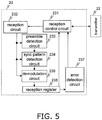
- FIG. 5 is a block diagram of the receiver 23, and FIG. 6 , which is a control flowchart for the receiver 23.
- the receiver 23 has a reception control circuit 231, a reception circuit 232, a preamble detection circuit 233, a sync pattern detection circuit 234, a demodulation circuit 235, a reception register 236, and an error detection circuit 237.
- the reception control circuit 231 receives a reception commencement command from the transmitter 22, and controls the reception circuit 232.
- the reception circuit 232 performs detection of carrier waves from received signals, gain control, conversion to intermediate frequencies, and other such processing, and transfers the processed data to the preamble detection circuit 233, the sync pattern detection circuit 234, and the demodulation circuit 235.
- the preamble detection circuit 233 performs detection of a preamble pattern. When a preamble pattern is detected, the preamble detection circuit 233 outputs an actuation pulse to the sync pattern detection circuit 234.
- the sync pattern detection circuit 234 performs detection of a sync pattern from reception data outputted from the reception circuit 232, by means of the actuation pulse from the preamble detection circuit 233.
- the demodulation circuit 235 performs demodulation of reception data using as a reference the sync pattern detected by the sync pattern detection circuit 234.
- the reception register 236 stores the reception data demodulated by the demodulation circuit 235.
- the error detection circuit 237 performs error detection on reception data, and outputs the result to the reception control circuit 231.
- the reception control circuit 231 Upon receipt of a result notification from the error detection circuit 237, the reception control circuit 231 outputs to the transmitter 22 information to the effect that an acknowledge signal has been received if no error was detected in the reception data and a code indicating an acknowledge signal was present in a specific region of the reception data, and otherwise outputs information to the effect that there was no acknowledge signal, and ends the reception operation.
- the reception control circuit 231 also ends the reception operation when a reception end signal has been received from the transmitter 22.
- FIG. 7 is a block diagram of the storage component 24, the transmission power and the blood glucose level storage format shown in FIG. 8 , and the storage component 24 control flowchart of FIG. 9 .
- the storage component 24 has a memory 241, a memory control circuit 242, an arbitration circuit 243, a condition identification circuit 244, a current pointer 245, an address generation circuit 246, and a data register 247.
- blocks that read and write data to the storage component 24 include the blood glucose level detector 21, the transmitter 22, and the transmission power determiner 25. Since special access from the transmission power determiner 25 to the storage component 24 is performed, this will be discussed in detail at a later point.
- the blood glucose level detector 21 includes parameters necessary for finding a blood glucose level, which are loaded in a nonvolatile memory of the storage component 24 before shipment from the factory. Also, during blood glucose level measurement, parameters loaded before shipment from the factory are read out in order to convert from a voltage value to a blood glucose level.
- the transmitter 22 loads various information (day of the week, transmission time (h), whether or not an acknowledge signal has been received (ACK), transmission power, and blood glucose level) according to the format shown in FIG. 8 .
- the arbitration circuit 243 arbitrates a memory access request from the blood glucose level detector 21 and the transmitter 22, and allocates a memory access right to the block that outputted a memory access request.
- the block to which the memory access right was allocated transfers write data to the storage component 24 if the access direction information (whether it is memory read or memory write) is memory write.
- the data register 247 temporarily loads write data and read data to the memory 241.
- the memory control circuit 242 produces a control signal for the memory 241.
- the memory control circuit 242 performs access control with respect to the memory 241 upon supply of access direction information.
- the memory 241 is a memory that stores data, such as an EEPROM or a DRAM. Since the parameters for finding a blood glucose level are put in memory before shipment from the factory, the memory 241 comprises either a nonvolatile memory alone, or a nonvolatile memory plus a volatile memory.
- the write address and write data are outputted to the memory 241 from the address generation circuit 246 and the data register 247, respectively, under control of the memory control circuit 242, and processing is ended at the point when the data is written to the memory 241.
- the data read out from the memory 241 is temporarily stored in the data register 247. The read data stored in the data register 247 is transferred to the block subject to memory access, and memory read processing ends.
- the memory access to the memory 241 is memory write from the transmitter 22, for example, then after the day of the week, the transmission time (h), whether or not an acknowledge signal has been received, transmission power, and blood glucose level data are written to the address indicated by the current pointer 245 of the memory 241, the value of the current pointer 245 is increased by 4 bytes. If the value of the current pointer 245 indicated the head of the DATA 255 in FIG. 8 before the current pointer 245 was increased by 4, then the value of the current pointer 245 is changed to a value indicating the head of DATA0.
- a memory access request signal from the transmission power determiner 25 to the storage component 24 is arbitrated by the arbitration circuit 243. If a memory access right is granted to the transmission power determiner 25, the condition identification circuit 244 performs data extraction by searching, in the reverse order from that stored in the storage component 24 (that is, starting from the most recent point), on the basis of the extraction conditions (transmission power determination rule) inputted at the interface 26.
- condition identification circuit 244 decides whether it is data for the same day of the week as that at the time of use, data for the same time period, data that is unrelated to the day of week or time period, or data for the same day of the week and the same time period.
- history information is extracted on the basis of the empirical rule that it is most likely that on a given day of the week or at a given time period, the user will generally use the wireless blood glucose meter 2 in the same place, that is, in the same environment. Consequently, the transmission power in transmission by the transmitter can be determined according to the usage environment.
- the transmission power determiner 25 then continues memory access to the storage component 24 until five sets of history information matching the extraction conditions have been found, or until all of the history information has been checked.
- the address generation circuit 246 stores the current value of the current pointer 245 once access of the transmission power determiner 25 starts, after which a four-byte address is outputted as a memory address to the memory control circuit 242 from the value indicated by the current pointer 245 in the direction of decreasing addresses, for each memory address.
- the memory control circuit 242 reads four bytes of data from the memory 241 by using the memory address received from the address generation circuit 246.
- the data that is read out is stored in the data register 247.
- the condition identification circuit 244 analyzes the data stored in the data register 247, and determines whether or not it matches the history conditions received from the interface 26. If there are fewer than five sets of data matching the history conditions, the condition identification circuit 244 repeats memory read while subtracting four bytes at a time from the value of the memory current pointer 245 that manages the address of the memory storing information related to transmission data. However, once all of the history information has been read, access is ended even though there are fewer than five sets of data matching the history conditions. When access is ended, the value of the current pointer 245 is returned to the value that was stored at the start of access.
- FIG. 10 is a block diagram of the transmission power determiner 25, and FIG. 11 , which is a control flowchart for the transmission power determiner 25.
- the transmission power determiner 25 comprises a transmission power control circuit 251, a conversion table 252, a transmission power selector 253, and a transmission power register 254.
- the transmission power control circuit 251 controls the conversion table 252 and the transmission power control circuit 251.
- the conversion table 252 outputs a power value that is 2dBm greater than or 2dBm less than the power outputted by the transmission power control circuit 251.
- the transmission power selector 253 switches the transmission power stored in the transmission power register 254.
- the transmission power register 254 outputs the transmission power stored as the optimal power to the transmitter 22.
- NA in the control flowchart of FIG. 11 indicates a count value indicating the number of pieces of history information for which there was no receipt of an acknowledge signal in the history information read out from the storage component 24.
- the transmission power control circuit 251 checks whether the blood glucose level is at least 400 mg/dl when blood glucose level data and an actuation pulse are outputted from the blood glucose level detector 21.
- the transmission power control circuit 251 switches the transmission power selector 253 and stores the maximum transmission power in the transmission power register 254.
- the transmission power register 254 then outputs the maximum transmission power stored as the optimal power to the transmitter 22. This makes it possible to minimize the loss of transmission due to insufficient transmission power in situations where urgent care by a physician or the like is necessary.
- the transmission power control circuit 251 sends a memory access request to the storage component 24.
- the transmission power control circuit 251 checks whether the history information includes information about whether or not an acknowledge signal has been received, and counts the number without receipt of an acknowledge signal in the received history information as NA (NO ACK).
- the transmission power control circuit 251 will switch the transmission power selector 253 so that a value that is 2 dBm less than the latest transmission power is outputted, and store this in the transmission power register 254.
- the transmission power control circuit 251 will switch the transmission power selector 253 so as to output at the -5 dBm specified as the minimum power, and store this in the transmission power register 254.
- the transmission power in transmission by the transmitter 22 can be reduced while still allowing communication between the portable terminal 3 and the wireless blood glucose meter 2, thus achieving a power saving.
- the transmission power control circuit 251 will switch the transmission power selector 253 so that a value that is 2 dBm greater than this transmission power is outputted, and store this in the transmission power register 254.
- the transmission power control circuit 251 will switch the transmission power selector 253 so as to output at the +5 dBm specified as the maximum power, and store this in the transmission power register 254.
- the transmission power selector 253 selects the power outputted by the transmission power control circuit 251 so that the most recent transmission power included in the history information will be stored in the transmission power register 254.
- the transmission power in transmission by the transmitter 22 can be determined more optimally so that the data sent from the wireless blood glucose meter 2 can be properly received by the portable terminal 3.
- the transmission power selector 253 selects the initial power when the user begins to use the wireless blood glucose meter 2, or when no history information has been stored in the storage component 24 due to software resetting or the like.
- the "initial power” here is enough power for radio waves to reach, assuming normal use, and is, for example, an intermediate value between the maximum transmission power and the minimum transmission power at which communication is possible.
- the transmission power register 254 then outputs the power stored as the optimal power to the transmitter 22.
- FIG. 12 is a block diagram of the interface 26.
- the user adjusts the settings by using the operating setting component 261 while checking the setting categories displayed on the display component 262.
- the setting categories here include the day of the week, the time, the history conditions for determining the transmission power (setting whether to use data for the same day of the week, data for the same time period, data that is unrelated to the day of week or time period, or data for the same day of the week and the same time period as the history information), and other such information.
- the history conditions set with the operating setting component 261 are outputted to the transmission power determiner 25. Meanwhile, the day of the week and time are outputted to a time manager 264.
- the time manager 264 manages the current day of the week and time along with the setting information.
- the information about day of the week and time managed in the time manager 264 is outputted to the transmitter 22.
- the display component 262 displays the calculated blood glucose level. If the calculated blood glucose level is 50 mg/dL or less, the user (diabetes patient) is in an extremely dangerous situation, so the alarm sound output component 263 outputs an alarm sound in order to alert any people around the user to this danger. It is conceivable that the user may have lost consciousness, so the display component 262 displays an emergency contact telephone number or information related to emergency measures, such as ingesting sugar.
- the wireless blood glucose meter 2 in another embodiment of the present invention will now be described through reference to FIGS. 13 to 17 .
- This embodiment differs from the first embodiment in that a noise power acquisition component (noise power measurement component) 28 is provided to calculate the transmission power in transmission by the transmitter 22, and the noise power measured in the noise power acquisition component 28 is also taken into account.
- a noise power acquisition component noise power measurement component 28
- the parts that are in common with the first embodiment will not be described again, and only the control flow of the receiver 23, the format of data storage in the memory 241, and the transmission power determiner 25 that are different from the first embodiment will be described in detail.
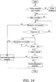
- FIG. 13 is a block diagram of the receiver 23, and FIG. 14 , which is a control flowchart for the receiver 23.
- the noise power acquisition component 28 for receiving noise is added to the first embodiment (see FIG. 5 ).
- the noise power acquisition component 28 acquires the noise power around where the noise power acquisition component 28 is installed, and outputs it to the transmitter 22.
- FIG. 14 a control flow for receiving noise is newly added to the first embodiment (see FIG. 6 ).
- the reception control circuit 231 starts the operation of the noise power acquisition component 28 under a noise reception start command from the transmission control circuit 221.
- the noise power acquisition component 28 measures the reception power in the frequency band used for communication.
- the reception control circuit 231 stops the operation of the noise power acquisition component 28 when a noise reception end command is inputted from the transmission control circuit 221. Then, the noise power acquisition component 28 sends the received noise power to the transmission power determiner 25.
- the difference in the storage component 24 from that in the first embodiment (see FIG. 8 ) is that noise power is stored in the memory 241 as shown in FIG. 15 .
- FIG. 16 is a block diagram of the transmission power determiner 25, and FIG. 17 , which is a control flowchart for the transmission power determiner 25.
- the conversion table 252 is deleted from the first embodiment (see FIG. 10 ), and a power computation circuit 255 that calculates the optimal power and a noise power register 256 that stores the noise power outputted from the noise power acquisition component 28 are added.
- the noise power outputted from the noise power acquisition component 28 is stored in the noise power register 256.
- the transmission power control circuit 251 checks whether the blood glucose level is at least 400 mg/dL.
- the transmission power register 254 switches the transmission power selector 253 and outputs the maximum transmission power as the optimal power to the transmitter 22.
- the transmission power control circuit 251 sends a memory access request to the storage component 24.
- history information is transferred as read data from the storage component 24 to the transmission power control circuit 251.
- the power computation circuit 255 outputs power so that the noise ratio of the noise power register 256 with respect to the output of the power computation circuit 255 is 0.9 times, 1.0 times, and 1.1 times the noise ratio of the noise power with respect to the transmission power of the most recent history information (labeled as x0.9, ⁇ 1.0, and ⁇ 1.1 in FIG. 16 ). Also, the transmission power control circuit 251 checks whether or not an acknowledge signal receipt is included in the history information, and counts the number where there is no acknowledge signal receipt in the received history information as NA (no acknowledge).
- the transmission power control circuit 251 switches the transmission power selector 253 so that a value that is 1.1 times as calculated by the power computation circuit 255 is stored in the transmission power register 254.
- the transmission power control circuit 251 switches the transmission power selector 253 so that a value that is 1.0 times as calculated by the power computation circuit 255 is stored in the transmission power register 254.
- the transmission power in transmission by the transmitter 22 can be reduced while still allowing communication between the portable terminal 3 and the wireless blood glucose meter 2, thus achieving a power saving.
- the transmission power control circuit 251 switches the transmission power selector 253 so that a value that is 0.9 times as calculated by the power computation circuit 255 is stored in the transmission power register 254.
- the transmission power control circuit 251 switches the transmission power selector 253 so that a value that is 1.0 times as calculated by the power computation circuit 255 is stored in the transmission power register 254.
- the transmission power in transmission by the transmitter 22 can be determined more optimally so that the data sent from the wireless blood glucose meter 2 can be received by the portable terminal 3.
- the transmission power control circuit 251 switches the transmission power selector 253 so that a value of 1.0 times as calculated by the power computation circuit 255 is stored in the transmission power register 254. Consequently, the optimal transmission power is supplied to the transmitter 22. If no history information has been stored in the storage component 24, the selection of the initial power is the same as in FIG. 10 .
- a blood glucose level measurement system (biological sample measurement system) 4 pertaining to an embodiment of the present invention will now be described through reference to FIGS. 18 to 21 .
- This embodiment differs from the first embodiment in that the reception power in data reception by a portable terminal (external device) 3 from a wireless blood glucose meter 2 is included in the acknowledge signal sent from the portable terminal 3 to the wireless blood glucose meter 2. Accordingly, differences from the first embodiment are the format of the data stored in the memory 241 of the storage component 24, the method for accessing this memory 241, and the method for determining the transmission power. These points will be described in detail, but the rest of the constitution and operation that are the same as in the first embodiment will not be described again.
- the acknowledge signal sent from the portable terminal 3 and received by the receiver 23 is composed of status information and the reception power when data is received by the portable terminal 3.
- the transmitter 22 sends blood glucose level data to the portable terminal 3, after which the storage component 24 is instructed to store various information (day of the week, transmission hour (time), transmission power,whether or not an acknowledge signal has been received (ACK), reception power in reception by the portable terminal 3, reference reception power, and blood glucose level) according to the format shown in FIG. 18 .
- the reference reception power will be discussed below.
- FIG. 19 is a block diagram of the transmission power determiner 25, and FIG. 20 , which is a control flowchart for the transmission power determiner 25.
- the transmission power determiner 25 comprises a transmission power control circuit 251, a conversion table 252, a transmission power selector 253, a transmission power register 254, and a reception power selector 255.
- the transmission power control circuit 251 controls the conversion table 252 and the transmission power control circuit 251.
- the conversion table 252 outputs a power value that is 2dBm greater than or 2dBm less than the power outputted by the transmission power control circuit 251.
- the transmission power selector 253 switches the transmission power stored in the transmission power register 254.
- the transmission power register 254 outputs the transmission power stored as the optimal power to the transmitter 22.
- the reception power selector 255 switches the reference reception power set as the optimal reception power when the portable terminal 3 receives blood glucose level data.
- NA in the control flowchart of FIG. 20 indicates a count value indicating the number of pieces of history information for which there was no receipt of an acknowledge signal in the history information read out from the storage component 24.
- the transmission power control circuit 251 checks whether the blood glucose level is at least 400 mg/dL when blood glucose level data and an actuation pulse are outputted from the blood glucose level detector 21.
- the transmission power control circuit 251 switches the transmission power selector 253 and stores the maximum transmission power in the transmission power register 254.
- the transmission power register 254 then outputs the maximum transmission power stored as the optimal power to the transmitter 22. This makes it possible to minimize the loss of transmission due to insufficient transmission power in situations where urgent care by a physician or the like is necessary.
- the transmission power control circuit 251 sends a memory access request to the storage component 24.
- the transmission power control circuit 251 checks whether the history information includes information about whether or not an acknowledge signal has been received, and counts the number without receipt of an acknowledge signal in the received history information as NA (no acknowledge).
- the transmission power control circuit 251 inputs the reference reception power to the conversion table 252, and if the most recent transmission power included in the history information (latest transmission power) is not equal to or lower than the -5 dBm specified as the minimum power (indicating that the initial power was -5 dBm), the transmission power control circuit 251 will switch the reception power selector 255 so that a value that is 2 dBm less than the reference reception power is calculated as a new reference reception power, and store this in the storage component 24.
- the transmission power control circuit 251 will switch the reception power selector 255 so as to output at the current reference reception power, and store this in the storage component 24.
- the transmission power control circuit 251 inputs the reference reception power to the conversion table 252, and if the latest transmission power is not at least the +5 dBm specified as the maximum power (indicating that the initial power was +5 dBm), the transmission power control circuit 251 will switch the reception power selector 255 so that a value that is 2 dBm greater than the reference reception power is calculated as a new reference reception power, and store this in the storage component 24. On the other hand, if the latest transmission power is at least the +5 dBm specified as the maximum power, the transmission power control circuit 251 will switch the reception power selector 255 so as to output at the current reference reception power, and store this in the storage component 24.
- the transmission power control circuit 251 compares the reference reception power with the reception power for the most recent history information (latest reception power). If the latest reception power is at least 5 dBm greater than the newly calculated reference reception power, the transmission power control circuit 251 inputs the transmission power for the history information to the conversion table 252 and switches the transmission power selector 253 so that a value that is 2 dBm less than the latest transmission power is calculated as a new transmission power, and stores this in the transmission power register 254.
- the transmission power register 254 then outputs the power stored as the optimal power to the transmitter 22.
- the transmission power in transmission by the transmitter 22 can be reduced while still allowing communication between the portable terminal 3 and the wireless blood glucose meter 2, thus achieving a power saving.
- the transmission power control circuit 251 inputs the transmission power for the history information to the conversion table 252 and switches the transmission power selector 253 so that a value that is 2 dBm greater than the latest transmission power is calculated as a new transmission power, and stores this in the transmission power register 254.
- the transmission power control circuit 251 stores this in the transmission power register 254 without making any changes to the latest transmission power.
- the transmission power register 254 then outputs the power stored as the optimal power to the transmitter 22.
- the transmission power in transmission by the transmitter 22 can be determined optimally so that the data sent by the wireless blood glucose meter 2 can be properly received by the portable terminal 3.
- the transmission power selector 253 selects the initial power when the user begins to use the wireless blood glucose meter 2, or when no history information has been stored in the storage component 24 due to software resetting or the like.
- the "initial power” here is enough power for radio waves to reach, assuming normal use, and is, for example, an intermediate value between the maximum transmission power and the minimum transmission power at which communication is possible.
- the reference reception power is set on the basis of the reception power when the portable terminal 3 on the reception side actually receives blood glucose level data, and the transmission power can be determined, so the transmission power can be properly optimized even if the transmission power in transmission by the wireless blood glucose meter 2 and the reception power in reception by the portable terminal 3 are different due to the external environment or the like.
- FIG. 21 is a block diagram of the portable terminal 3. As shown in FIG. 21 , the portable terminal 3 has a receiver (external receiver) A1, a reception power determiner A2, an error detector A3, a storage component A4, a transmission power selector A5, and a transmitter (external transmitter) A6.
- a receiver external receiver
- A2 reception power determiner
- A3 reception power determiner
- A3 storage component
- A4 transmission power selector
- A6 a transmitter (external transmitter) A6.
- the receiver A1 detects carrier waves from the received signals, and outputs to the reception power determiner A2. It also uses a preamble pattern or sync pattern of the received signals to demodulate transmission data, and outputs the demodulated data to the error detector A3.
- the reception power determiner A2 calculates the reception power in the reception of data by the receiver A1 from the carrier wave outputted from the receiver A1, and compares this with a specific value.
- the reception power is outputted to the transmitter A6, and the comparison result to the transmission power selector A5.
- the specific value here is set by the transmission power determiner 25 in the wireless blood glucose meter 2 to a value that is greater than the lower limit power at which the portable terminal 3 can receive, and less than the -5 dBm specified as the minimum power in transmission.
- this specific value is the remainder of subtracting the power that attenuates at the distance between the portable terminal 3 and the wireless blood glucose meter 2 assumed in normal usage from the above-mentioned minimum power (-5 dBm).
- the transmission power selector A5 instructs the transmitter A6 to set the transmission power to the maximum power when a result is transmitting indicating that the reception power is below the specific value.
- the error detector A3 performs error detection on the demodulated data outputted from the receiver A1 by using an error detection code added to this data. If the result of error detection is that there are no errors, measurement data is taken out of the demodulated data and outputted to the storage component A4. The transmitter A6 is then notified that the measurement data has been properly received.
- the storage component A4 stores the measurement data outputted from the error detector A3.
- the transmitter A6 sends an acknowledge signal to the wireless blood glucose meter 2 upon being notified that the measurement data has been properly received from the error detector A3.
- the reception power measured by the reception power determiner A2 is included in this acknowledge signal. If the reception power determiner A2 here has sent out a notification that the reception power is lower than the specific value, transmission is performed at the maximum power at which transmission is possible.
- the transmitter A6 sends an non-acknowledge signal to the wireless blood glucose meter 2 (interpreted at the wireless blood glucose meter 2 to mean that data transmission was not carried out properly). At this point, transmission is performed at the maximum power at which transmission is possible, regardless of the determination result of the reception power determiner A2.
- the acknowledge signal can reliably reach the wireless blood glucose meter 2 even in a situation in which the wireless blood glucose meter 2 and the portable terminal 3 are farther apart than normal, or in which there is an obstruction or the like between the wireless blood glucose meter 2 and the portable terminal 3, so that the radio waves are attenuated more than expected along the way. Consequently, there will be no cases in which an acknowledge signal cannot be received at the wireless blood glucose meter 2 even though the data was sent properly from the wireless blood glucose meter 2 to the portable terminal 3, and this prevents the wireless blood glucose meter 2 from deciding that the data was not sent properly and resending the data.
- the measurement apparatus may be one that measures lactic acid, uric acid, or the like, and as long as it is an apparatus that wirelessly transmits this data to another terminal or the like, the effect will be the same as that with the wireless blood glucose meter 2 pertaining to the above embodiment.
- the condition for extracting history information was extracting history information for the same day of the week and the same time period as during measurement, but the present invention is not limited to this.
- the condition may be such that extraction is performed in the order of newest to oldest, or may be such that extraction is performed on the same day of the week and in the same time period as during measurement and from the newest entry.
- the extraction condition (the transmission power determination rule) allows it to be matched to the usage conditions of the person using the wireless blood glucose meter.
- the transmission power control circuit 251 switched the transmission power selector 253 so that a value 2 dBm less than or greater than the latest transmission power would be outputted according to the history information, but the present invention is not limited to this.
- the transmission power control circuit may switch the transmission power selector so that a value 3 dBm less than or greater than the latest transmission power is outputted, and the amount by which the value is greater or less does not matter.
- the value can be set to a suitable range as desired.
- the power computation circuit 255 determined the transmission power so that the noise ratio of the noise power register 256 to the transmission power, according to the history information and the measured noise, would be 0.9 times, 1.0 times, and 1.1 times the noise ratio of the noise power to the transmission power of the most recent history information, but the present invention is not limited to this.
- the noise ratio adjusted by the reception power selector 255 may be adjusted so that the result is 0.8 times, 1.0 times, and 1.2 times, and this adjustment ratio is not that important.
- the adjustment ratio can be set to a suitable range as desired.
- the transmission power control circuit 251 switched the reception power selector 255 so as to set to a value that is 2 dBm less than or greater than the reference reception power currently stored, according to the history information, but the present invention is not limited to this.
- the transmission power control circuit may switch the reception power selector so as to set to a value 3 dBm less than or greater than the reference reception power that has been set, and the amount by which the value is greater or less does not matter.
- the value can be set to a suitable range as desired.
- the transmission power control circuit 251 checked whether or not the blood glucose level was at least 400 mg/dL when blood glucose level data and an actuation pulse were outputted from the blood glucose level detector 21, but the present invention is not limited to this.
- This number is nothing but a common index used by diabetes patients, and may instead be set to a value of 350 mg/dL, for example, as dictated by the user.
- the alarm sound output component 263 and the display component 262 emitted an alarm if the measured blood glucose level was 50 mg/dL or less, but here again these may be set as dictated by the user.
- control blocks shown in FIG. 1 were each constructed from a hardware function, but the present invention is not limited to this.
- control blocks shown in FIG. 1 may, for example, comprise a single piece of hardware or computer software, or hardware and computer software functions may be combined, and this may be suitably determined according to the processing capability and so forth.
- the biological sample measurement apparatus pertaining to the present invention affords less power consumption in communication using weak radio waves, and is useful as a biological sample measurement apparatus that performs wireless communication using a battery as its power supply.
Landscapes
- Health & Medical Sciences (AREA)
- Engineering & Computer Science (AREA)
- Life Sciences & Earth Sciences (AREA)
- Physics & Mathematics (AREA)
- Biomedical Technology (AREA)
- Biophysics (AREA)
- Molecular Biology (AREA)
- Pathology (AREA)
- Medical Informatics (AREA)
- General Health & Medical Sciences (AREA)
- Chemical & Material Sciences (AREA)
- Analytical Chemistry (AREA)
- Computer Networks & Wireless Communication (AREA)
- Hematology (AREA)
- Food Science & Technology (AREA)
- Medicinal Chemistry (AREA)
- Human Computer Interaction (AREA)
- Biochemistry (AREA)
- Optics & Photonics (AREA)
- General Physics & Mathematics (AREA)
- Immunology (AREA)
- Databases & Information Systems (AREA)
- Urology & Nephrology (AREA)
- Heart & Thoracic Surgery (AREA)
- Surgery (AREA)
- Animal Behavior & Ethology (AREA)
- Public Health (AREA)
- Veterinary Medicine (AREA)
- Measurement Of The Respiration, Hearing Ability, Form, And Blood Characteristics Of Living Organisms (AREA)
- Measuring And Recording Apparatus For Diagnosis (AREA)
- Investigating Or Analysing Biological Materials (AREA)
- Near-Field Transmission Systems (AREA)
- Mobile Radio Communication Systems (AREA)
Claims (21)
- Messvorrichtung für biologische Proben (2) zum drahtlosen Kommunizieren mit einer externen Vorrichtung (3), Folgendes umfassend:eine Messkomponente für biologische Daten (21) zum Messen biologischer Daten;einen Sender (22) zum Übertragen der biologischen Daten, die von der Messkomponente für biologische Daten (21) gemessen werden;einen Empfänger (23) zum Empfangen eines Bestätigungssignals, das zurückgesendet wird, wenn die externe Vorrichtung (3) die von dem Sender (22) übertragenen biologischen Daten korrekt empfangen hat;eine Speicherkomponente (24) zum Speichern einer Verlaufsinformation, ob das Bestätigungssignal empfangen wurde oder nicht, und Übertragungsleistung, wenn der Sender (22) die biologischen Daten übertragen hat; undeine Übertragungsleistungs-Bestimmungseinrichtung (25) zum Extrahieren einer Verlaufsinformation aus der Speicherkomponente (24) gemäß einer Übertragungsleistungs-Bestimmungsregel, welche Extraktionsbedingungen zum Extrahieren einer Verlaufsinformation für dieselbe Verwendungsumgebung festlegt, wobei die Extraktionsbedingungen so festgelegt sind, dass die Verlaufsinformation für denselben Wochentag und dieselbe Zeitperiode wie die aktuelle Messzeit extrahiert wird,und zum Bestimmen der Übertragungsleistung des Senders (22), basierend darauf, ob ein Bestätigungssignal empfangen wurde oder nicht, und auf der Grundlage der Übertragungsleistung, die als extrahierte Verlaufsinformation gespeichert ist, wobei die Übertragungsleistung bestimmt wird, bevor der Sender (22) die biologischen Daten überträgt.
- Messvorrichtung für biologische Proben (2) nach Anspruch 1,wobei die Übertragungsleistungs-Bestimmungseinrichtung (25) eine spezifische Anzahl von Teilen der Verlaufsinformation gemäß der Übertragungsleistungs-Bestimmungsregel extrahiert und die Übertragungsleistung des Senders (22) bestimmt, so dass die Übertragungsleistung des Senders (22) niedriger ist als die Übertragungsleistung, die als die Verlaufsinformation gespeichert ist, wenn die extrahierte Verlaufsinformation mindestens eine spezifische Anzahl von Teilen der Verlaufsinformation enthält, für die das Bestätigungssignal empfangen wurde.
- Messvorrichtung für biologische Proben (2) nach Anspruch 1,wobei die Übertragungsleistungs-Bestimmungseinrichtung (25) eine spezifische Anzahl von Teilen der Verlaufsinformation gemäß der Übertragungsleistungs-Bestimmungsregel extrahiert und die Übertragungsleistung des Senders (22) bestimmt, so dass die Übertragungsleistung des Senders (22) höher ist als die Übertragungsleistung, die als die Verlaufsinformation gespeichert ist, wenn die extrahierte Verlaufsinformation nicht mindestens eine spezifische Anzahl von Teilen der Verlaufsinformation enthält, für die das Bestätigungssignal empfangen wurde.
- Messvorrichtung für biologische Proben (2) nach einem der Ansprüche 1 bis 3, weiterhin umfassend eine Rauschleistungsmesskomponente (28) zum Messen von Rauschleistung unmittelbar vor dem Übertragen durch den Sender (22), wobei die Speicherkomponente (24) ferner die von der Rauschleistungsmesskomponente (28) gemessene Rauschleistung als die Verlaufsinformation speichert.
- Messvorrichtung für biologische Proben (2) nach Anspruch 4,wobei die Übertragungsleistungs-Bestimmungseinrichtung (25) die Verlaufsinformation extrahiert, für die das Bestätigungssignal gemäß der Übertragungsleistungs-Bestimmungsregel empfangen wurde, und die Übertragungsleistung des Senders (22) auf der Grundlage der von der Rauschleistungsmesskomponente (28) gemessenen Rauschleistung bestimmt, so dass ein Verhältnis der gemessenen Rauschleistung zu der Übertragungsleistung des Senders (22) gleich einem Verhältnis der Rauschleistung zu der Übertragungsleistung in der extrahierten Verlaufsinformation ist.
- Messvorrichtung für biologische Proben (2) nach Anspruch 4,wobei die Übertragungsleistungs-Bestimmungseinrichtung (25) eine spezifische Anzahl von Teilen der Verlaufsinformation gemäß der Übertragungsleistungs-Bestimmungsregel extrahiert und die Übertragungsleistung des Senders (22) bestimmt, auf der Basis der von der Rauschleistungsmesskomponente (28) gemessenen Rauschleistung, so dass ein Verhältnis der gemessenen Rauschleistung zu der Übertragungsleistung des Senders (22) größer ist als das Verhältnis der Rauschleistung zu der Übertragungsleistung in der Verlaufsinformation, wenn die extrahierte Verlaufsinformation mindestens eine spezifische Anzahl von Teilen der Verlaufsinformation enthält, für die das Bestätigungssignal empfangen wurde.
- Messvorrichtung für biologische Proben (2) nach Anspruch 4,wobei die Übertragungsleistungs-Bestimmungseinrichtung (25) eine spezifische Anzahl von Teilen der Verlaufsinformation gemäß der Übertragungsleistungs-Bestimmungsregel extrahiert und die Übertragungsleistung des Senders (22) bestimmt, in Bezug auf die von der Rauschleistungsmesskomponente (28) gemessenen Rauschleistung, so dass ein Verhältnis der gemessenen Rauschleistung zu der Übertragungsleistung des Senders (22) kleiner ist als das Verhältnis der Rauschleistung zu der Übertragungsleistung in der Verlaufsinformation, wenn die extrahierte Verlaufsinformation nicht mindestens eine spezifische Anzahl von Teilen der Verlaufsinformation enthält, für die das Bestätigungssignal empfangen wurde.
- Messvorrichtung für biologische Proben (2) zum drahtlosen Kommunizieren mit einer externen Vorrichtung (3), Folgendes umfassend:eine Messkomponente für biologische Daten (21) zum Messen biologischer Daten;einen Sender (22) zum Übertragen der biologischen Daten, die von der Messkomponente für biologische Daten (21) gemessen werden;einen Empfänger (23) zum Empfangen eines Bestätigungssignals, das zurückgeführt wird, wenn die externe Vorrichtung (3) die von dem Sender (22) übertragenen biologischen Daten korrekt empfangen hat;eine Speicherkomponente (24) zum Speichern einer Referenzempfangsleistung, welche die optimale Empfangsleistung ist, wenn die externe Vorrichtung (3) die biologischen Daten empfängt, und der Verlaufsinformation, die umfasst, ob das Bestätigungssignal empfangen wurde oder nicht, und der Übertragungsleistung, wenn der Sender (22) die biologischen Daten übertragen hat, und der Empfangsleistung, wenn die externe Vorrichtung (3) die biologischen Daten empfangen hat; undeine Übertragungsleistungs-Bestimmungseinrichtung (25) zum Extrahieren einer Verlaufsinformation aus der Speicherkomponente (24) gemäß einer Übertragungsleistungs-Bestimmungsregel, welche Extraktionsbedingungen zum Extrahieren einer Verlaufsinformation für dieselbe Verwendungsumgebung festlegt, und zum Bestimmen der Übertragungsleistung des Senders (22), basierend darauf, ob ein Bestätigungssignal empfangen wurde oder nicht, und auf der Grundlage der Übertragungsleistung, die als extrahierte Verlaufsinformation gespeichert ist, wobei die Übertragungsleistung bestimmt wird, bevor der Sender (22) die biologischen Daten überträgt, wobei die Extraktionsbedingungen so festgelegt sind, dass die Verlaufsinformation für denselben Wochentag und denselben Zeitraum wie die aktuelle Messzeit extrahiert wird.
- Messvorrichtung für biologische Proben (2) nach Anspruch 8,wobei die Übertragungsleistungs-Bestimmungseinrichtung (25) einen Teil der Verlaufsinformation gemäß der Übertragungsleistungs-Bestimmungsregel extrahiert und die Empfangsleistung in der extrahierten Verlaufsinformation mit der Referenzempfangsleistung vergleicht, und wenn die Empfangsleistung höher ist, die Übertragungsleistung - wenn der Sender (22) übermittelt - so bestimmt wird, dass sie niedriger ist als die Übertragungsleistung, die als die extrahierte Verlaufsinformation gespeichert ist, und wenn die Empfangsleistung niedriger ist, die Übertragungsleistung - wenn der Sender (22) übermittelt - so bestimmt wird, dass sie höher ist als die Übertragungsleistung, die als die extrahierte Verlaufsinformation gespeichert ist.
- Messvorrichtung für biologische Proben (2) nach Anspruch 8 oder 9,wobei die Übertragungsleistungs-Bestimmungseinrichtung (25) eine spezifische Anzahl von Teilen der Verlaufsinformation gemäß der Übertragungsleistungs-Bestimmungsregel extrahiert, und wenn die extrahierte Verlaufsinformation mindestens eine spezifische Anzahl von Teilen der Verlaufsinformation enthält, für die das Bestätigungssignal empfangen wird, die Referenzempfangsleistung niedriger als der in der Speicherkomponente (24) gespeicherte Wert festgelegt wird.
- Messvorrichtung für biologische Proben (2) nach Anspruch 8 oder 9,wobei die Übertragungsleistungs-Bestimmungseinrichtung (25) eine spezifische Anzahl von Teilen der Verlaufsinformation gemäß der Übertragungsleistungs-Bestimmungsregel extrahiert, und wenn die extrahierte Verlaufsinformation nicht mindestens eine spezifische Anzahl von Teilen der Verlaufsinformation enthält, für die das Bestätigungssignal empfangen wird, die Referenzempfangsleistung höher als der in der Speicherkomponente (24) gespeicherte Wert festgelegt wird.
- Messvorrichtung für biologische Proben (2) nach einem der Ansprüche 1 bis 11,wobei die Übertragungsleistungs-Bestimmungsregel festgelegt ist, um die Verlaufsinformation in der Reihenfolge von neu nach alt zu extrahieren.
- Messvorrichtung für biologische Proben (2) nach einem der Ansprüche 1 bis 12,wobei die Übertragungsleistungs-Bestimmungsregel festgelegt ist, um die Verlaufsinformation für denselben Wochentag zu extrahieren, wie wenn die Verlaufsinformation durch die Übertragungsleistungs-Bestimmungseinrichtung (25) extrahiert wird.
- Messvorrichtung für biologische Proben (2) nach einem der Ansprüche 1 bis 13,wobei die Übertragungsleistungs-Bestimmungsregel festgelegt ist, um die Verlaufsinformation für dieselbe Zeitperiode zu extrahieren, wie wenn die Verlaufsinformation durch die Übertragungsleistungs-Bestimmungseinrichtung (25) extrahiert wird.
- Messvorrichtung für biologische Proben (2) nach einem der Ansprüche 1 bis 14,wobei die Übertragungsleistungs-Bestimmungseinrichtung (25) die maximale Übertragungsleistung bestimmt, die der Sender (22) ausgeben kann, wenn die biologischen Daten, die von der Messkomponente für biologische Daten gemessen werden, nicht einen Wert innerhalb eines bestimmten Bereichs darstellen.
- Messvorrichtung für biologische Proben nach einem der Ansprüche 1 bis 15, ferner umfassendeine Schnittstelle (26) mit einer Anzeigekomponente (262) zum Anzeigen der biologischen Daten, die von der Messkomponente für biologische Daten (21) gemessen werden,eine Betriebseinstellungskomponente (261) zum Ermöglichen, dass der Benutzer verschiedene Betriebseinstellungen vornimmt, und eine Alarmtonausgabekomponente (263) zum Ausgeben eines Alarmtons,wobei, wenn der von der Messkomponente für biologische Daten (21) gemessene biologische Daten-Wert niedriger als ein spezifischer Wert ist, ein Alarmton von der Alarmtonausgabekomponente (263) ausgegeben wird und ein Notfallstatus auf der Anzeigekomponente (261) angezeigt wird.
- Messvorrichtung für biologische Proben (2) nach Anspruch 16,wobei der Notfallstatus eine Telefonnummer ist.
- Messvorrichtung für biologische Proben (2) nach Anspruch 16 oder 17,wobei der Notfallstatus ein Verfahren zum Behandeln von Hypoglykämie ist.
- Messvorrichtung für biologische Proben (2) nach einem der Ansprüche 1 bis 18,wobei die Messkomponente für biologische Daten (21) ein drahtloses Blutzuckermessgerät ist, das so eingerichtet ist, um einen Blutzuckerspiegel zu messen.
- Messsystem für biologische Proben, Folgendes umfassend:die Messvorrichtung für biologische Proben (2) nach einem der Ansprüche 8 bis 11; undeine externe Vorrichtung (3) mit einem externen Empfänger (A 1) zum Empfangen biologischer Daten, die von der Messvorrichtung für biologische Proben (2) übertragen werden, einen Fehlerdetektor (A 3) zum Bestimmen, ob der externe Empfänger (A 1) die biologischen Daten korrekt empfangen hat oder nicht, einen externen Sender (A 6) zum Übertragen eines Bestätigungssignals an die Messvorrichtung für biologische Proben (2), wenn der Fehlerdetektor (A 3) bestimmt hat, dass die biologischen Daten korrekt empfangen wurden, eine Empfangsleistungs-Bestimmungseinrichtung (A 2) zum Messen der Empfangsleistung, wenn der externe Empfänger (A 1) die biologischen Daten empfangen und mit einem spezifischen Wert verglichen hat, und eine Übertragungsleistungs-Auswahlvorrichtung (A 5) zum Auswählen der Übertragungsleistung des externen Senders (A 6) anhand des Bestimmungsergebnisses der Empfangsleistungs-Bestimmungseinrichtung (A 2).
- Messsystem für biologische Proben nach Anspruch 20,wobei die Übertragungsleistungs-Auswahlvorrichtung die maximale Leistung als die Übertragungsleistung in dem externen Sender auswählt, wenn die Empfangsleistungs-Bestimmungseinrichtung IO bestimmt hat, dass die Empfangsleistung, wenn die biologischen Daten von dem externen Empfänger empfangen wurden, niedriger als der spezifische Wert ist.
Applications Claiming Priority (5)
| Application Number | Priority Date | Filing Date | Title |
|---|---|---|---|
| JP2007333786 | 2007-12-26 | ||
| JP2008015643 | 2008-01-25 | ||
| JP2008015641 | 2008-01-25 | ||
| JP2008015642 | 2008-01-25 | ||
| PCT/JP2008/003756 WO2009081538A1 (ja) | 2007-12-26 | 2008-12-12 | 生体試料測定装置およびこれを備えた生体試料測定システム |
Publications (5)
| Publication Number | Publication Date |
|---|---|
| EP2229028A1 EP2229028A1 (de) | 2010-09-15 |
| EP2229028A8 EP2229028A8 (de) | 2011-04-13 |
| EP2229028A4 EP2229028A4 (de) | 2011-08-24 |
| EP2229028B1 true EP2229028B1 (de) | 2018-05-09 |
| EP2229028B8 EP2229028B8 (de) | 2018-07-04 |
Family
ID=40800856
Family Applications (1)
| Application Number | Title | Priority Date | Filing Date |
|---|---|---|---|
| EP08863718.6A Not-in-force EP2229028B8 (de) | 2007-12-26 | 2008-12-12 | Vorrichtung zur vermessung biologischer proben und system zur vermessung biologischer proben damit |
Country Status (4)
| Country | Link |
|---|---|
| US (1) | US8271015B2 (de) |
| EP (1) | EP2229028B8 (de) |
| JP (1) | JP5043810B2 (de) |
| WO (1) | WO2009081538A1 (de) |
Families Citing this family (13)
| Publication number | Priority date | Publication date | Assignee | Title |
|---|---|---|---|---|
| JP4544338B2 (ja) * | 2008-04-28 | 2010-09-15 | ソニー株式会社 | 送電装置、受電装置、送電方法、プログラム、および電力伝送システム |
| EP2618155A4 (de) * | 2010-09-16 | 2016-01-27 | Panasonic Healthcare Holdings Co Ltd | System zur messung biologischer proben |
| US8849459B2 (en) * | 2010-10-15 | 2014-09-30 | Roche Diagnostics Operations, Inc. | Power management system for a handheld medical device |
| CN102725767B (zh) * | 2010-11-30 | 2016-01-20 | 松下电器(美国)知识产权公司 | 通信装置以及通信方法 |
| WO2012131828A1 (ja) * | 2011-03-29 | 2012-10-04 | テルモ株式会社 | データ移送装置およびデータ移送システム |
| JP5535251B2 (ja) | 2011-04-26 | 2014-07-02 | アークレイ株式会社 | 試料測定装置および試料測定システム |
| US9526437B2 (en) | 2012-11-21 | 2016-12-27 | i4c Innovations Inc. | Animal health and wellness monitoring using UWB radar |
| US10149617B2 (en) | 2013-03-15 | 2018-12-11 | i4c Innovations Inc. | Multiple sensors for monitoring health and wellness of an animal |
| US10531401B2 (en) | 2014-03-20 | 2020-01-07 | Xiaomi Inc. | Method, terminal device and system for controlling transmission |
| JP6539545B2 (ja) * | 2015-08-28 | 2019-07-03 | 富士フイルム株式会社 | 検査装置及びその作動方法 |
| EP3301975B1 (de) * | 2016-09-28 | 2019-05-01 | Intel IP Corporation | Vorrichtungen und verfahren zur messung von benachbarten zellen auf anderen frequenzen oder in anderen rat sendend |
| JP7222616B2 (ja) * | 2018-06-13 | 2023-02-15 | 日本光電工業株式会社 | センサ、および生体情報監視システム |
| JP7123676B2 (ja) * | 2018-07-20 | 2022-08-23 | オムロンヘルスケア株式会社 | 生体データ測定システム及び生体データ測定方法 |
Family Cites Families (20)
| Publication number | Priority date | Publication date | Assignee | Title |
|---|---|---|---|---|
| JP2879836B2 (ja) * | 1991-08-07 | 1999-04-05 | ケイディディ株式会社 | 衛星通信・放送の送信電力制御方式 |
| KR19990008052A (ko) * | 1995-04-25 | 1999-01-25 | 마이클 피 노바 | 기억 장치를 갖는 원격적으로 프로그램 가능한 매트릭스 및 이의 용도 |
| JPH1079776A (ja) * | 1996-09-03 | 1998-03-24 | Toyota Motor Corp | 通信方法 |
| JPH10285109A (ja) | 1997-04-10 | 1998-10-23 | Matsushita Electric Ind Co Ltd | 無線携帯端末機 |
| JP2000188775A (ja) * | 1998-12-22 | 2000-07-04 | Canon Inc | 通信装置、通信システム、通信方法、及び記憶媒体 |
| JP2002142014A (ja) * | 2000-11-01 | 2002-05-17 | Canon Inc | 通信装置 |
| JP4742182B2 (ja) * | 2001-02-23 | 2011-08-10 | アークレイ株式会社 | データ送受信装置、データ管理装置、データ処理装置、およびプログラム |
| JP2003309495A (ja) * | 2002-04-16 | 2003-10-31 | Seiko Instruments Inc | データ電送装置 |
| GB2393356B (en) * | 2002-09-18 | 2006-02-01 | E San Ltd | Telemedicine system |
| JP3906168B2 (ja) * | 2003-02-28 | 2007-04-18 | 株式会社東芝 | 電子機器および同機器のシステム制御方法 |
| JP4354778B2 (ja) * | 2003-10-30 | 2009-10-28 | 京セラ株式会社 | 通信システム、通信装置、及び通信方法 |
| JP2006148484A (ja) * | 2004-11-18 | 2006-06-08 | Matsushita Electric Ind Co Ltd | 通信装置及び送信電力制御方法 |
| JP2006165742A (ja) * | 2004-12-03 | 2006-06-22 | Matsushita Electric Ind Co Ltd | 無線通信装置及び送信出力制御方法 |
| JP2006340952A (ja) * | 2005-06-10 | 2006-12-21 | Matsushita Electric Ind Co Ltd | 生体情報管理システム、およびそのプログラム |
| JP2007000188A (ja) * | 2005-06-21 | 2007-01-11 | Toshiba Corp | 医療支援装置 |
| JP2007013538A (ja) * | 2005-06-30 | 2007-01-18 | Matsushita Electric Ind Co Ltd | データ通信方法及びデータ通信装置 |
| JP2007075372A (ja) * | 2005-09-14 | 2007-03-29 | Mitsuba Corp | 生体信号監視装置 |
| JP4606308B2 (ja) * | 2005-11-15 | 2011-01-05 | 三菱電機株式会社 | 無線通信装置及び無線通信システム |
| US8798661B2 (en) * | 2005-12-23 | 2014-08-05 | Qualcomm Incorporated | Method and apparatus for determining output transmit power for an access channel in a wireless communication network |
| US8654868B2 (en) * | 2006-04-18 | 2014-02-18 | Qualcomm Incorporated | Offloaded processing for wireless applications |
-
2008
- 2008-12-03 JP JP2008309060A patent/JP5043810B2/ja active Active
- 2008-12-12 WO PCT/JP2008/003756 patent/WO2009081538A1/ja not_active Ceased
- 2008-12-12 US US12/600,582 patent/US8271015B2/en active Active
- 2008-12-12 EP EP08863718.6A patent/EP2229028B8/de not_active Not-in-force
Non-Patent Citations (1)
| Title |
|---|
| None * |
Also Published As
| Publication number | Publication date |
|---|---|
| EP2229028A4 (de) | 2011-08-24 |
| JP2009195679A (ja) | 2009-09-03 |
| EP2229028A8 (de) | 2011-04-13 |
| EP2229028B8 (de) | 2018-07-04 |
| US20100159835A1 (en) | 2010-06-24 |
| US8271015B2 (en) | 2012-09-18 |
| WO2009081538A1 (ja) | 2009-07-02 |
| EP2229028A1 (de) | 2010-09-15 |
| JP5043810B2 (ja) | 2012-10-10 |
Similar Documents
| Publication | Publication Date | Title |
|---|---|---|
| EP2229028B1 (de) | Vorrichtung zur vermessung biologischer proben und system zur vermessung biologischer proben damit | |
| US11298056B2 (en) | Methods and systems for early signal attenuation detection and processing | |
| US12396645B2 (en) | Analyte monitoring system and methods | |
| US8318096B2 (en) | Biological sample measurement apparatus | |
| US10750952B2 (en) | Continuous glucose monitoring system and methods of use | |
| US9226701B2 (en) | Error detection in critical repeating data in a wireless sensor system | |
| US20160317071A1 (en) | Method and apparatus for providing dynamic multi-stage signal amplification in a medical device | |
| US20090318789A1 (en) | Analyte Monitoring System and Methods | |
| US20130231544A1 (en) | Analyte Monitoring System And Methods | |
| US20100184478A1 (en) | Wireless communication system and personal digital assistant | |
| HK40007248A (en) | Method for a wireless data communication between a sensor system and a receiver, and system for a wireless data communication | |
| WO2013066847A1 (en) | Analyte sensor |
Legal Events
| Date | Code | Title | Description |
|---|---|---|---|
| PUAI | Public reference made under article 153(3) epc to a published international application that has entered the european phase |
Free format text: ORIGINAL CODE: 0009012 |
|
| 17P | Request for examination filed |
Effective date: 20100726 |
|
| AK | Designated contracting states |
Kind code of ref document: A1 Designated state(s): AT BE BG CH CY CZ DE DK EE ES FI FR GB GR HR HU IE IS IT LI LT LU LV MC MT NL NO PL PT RO SE SI SK TR |
|
| AX | Request for extension of the european patent |
Extension state: AL BA MK RS |
|
| RIN1 | Information on inventor provided before grant (corrected) |
Inventor name: ANDO, HIROSHI Inventor name: OOZAWA, AKIYOSHI Inventor name: AOKI, TOORU Inventor name: OKUDA, EIJI Inventor name: IMAI, NORIO Inventor name: MANABE, KAZUO |
|
| DAX | Request for extension of the european patent (deleted) | ||
| A4 | Supplementary search report drawn up and despatched |
Effective date: 20110722 |
|
| RIC1 | Information provided on ipc code assigned before grant |
Ipc: H04W 52/24 20090101ALI20110718BHEP Ipc: G01N 27/416 20060101ALI20110718BHEP Ipc: G01N 27/26 20060101ALI20110718BHEP Ipc: G01N 27/327 20060101ALI20110718BHEP Ipc: H04W 52/22 20090101AFI20110718BHEP Ipc: G06F 19/00 20110101ALI20110718BHEP |
|
| RAP1 | Party data changed (applicant data changed or rights of an application transferred) |
Owner name: PANASONIC HEALTHCARE CO., LTD. |
|
| 17Q | First examination report despatched |
Effective date: 20141209 |
|
| RAP1 | Party data changed (applicant data changed or rights of an application transferred) |
Owner name: PANASONIC HEALTHCARE HOLDINGS CO., LTD. |
|
| RAP1 | Party data changed (applicant data changed or rights of an application transferred) |
Owner name: PANASONIC HEALTHCARE HOLDINGS CO., LTD. |
|
| STAA | Information on the status of an ep patent application or granted ep patent |
Free format text: STATUS: EXAMINATION IS IN PROGRESS |
|
| REG | Reference to a national code |
Ref country code: DE Ref legal event code: R079 Ref document number: 602008055215 Country of ref document: DE Free format text: PREVIOUS MAIN CLASS: H04W0052220000 Ipc: A61B0005000000 |
|
| GRAP | Despatch of communication of intention to grant a patent |
Free format text: ORIGINAL CODE: EPIDOSNIGR1 |
|
| STAA | Information on the status of an ep patent application or granted ep patent |
Free format text: STATUS: GRANT OF PATENT IS INTENDED |
|
| RIC1 | Information provided on ipc code assigned before grant |
Ipc: G01N 33/487 20060101ALI20171122BHEP Ipc: A61B 5/00 20060101AFI20171122BHEP |
|
| INTG | Intention to grant announced |
Effective date: 20171221 |
|
| GRAS | Grant fee paid |
Free format text: ORIGINAL CODE: EPIDOSNIGR3 |
|
| GRAA | (expected) grant |
Free format text: ORIGINAL CODE: 0009210 |
|
| STAA | Information on the status of an ep patent application or granted ep patent |
Free format text: STATUS: THE PATENT HAS BEEN GRANTED |
|
| AK | Designated contracting states |
Kind code of ref document: B1 Designated state(s): AT BE BG CH CY CZ DE DK EE ES FI FR GB GR HR HU IE IS IT LI LT LU LV MC MT NL NO PL PT RO SE SI SK TR |
|
| REG | Reference to a national code |
Ref country code: GB Ref legal event code: FG4D |
|
| REG | Reference to a national code |
Ref country code: CH Ref legal event code: EP Ref country code: AT Ref legal event code: REF Ref document number: 996766 Country of ref document: AT Kind code of ref document: T Effective date: 20180515 |
|
| REG | Reference to a national code |
Ref country code: IE Ref legal event code: FG4D |
|
| REG | Reference to a national code |
Ref country code: DE Ref legal event code: R096 Ref document number: 602008055215 Country of ref document: DE |
|
| RAP2 | Party data changed (patent owner data changed or rights of a patent transferred) |
Owner name: PHC HOLDINGS CORPORATION |
|
| REG | Reference to a national code |
Ref country code: DE Ref legal event code: R082 Ref document number: 602008055215 Country of ref document: DE Representative=s name: EISENFUEHR SPEISER PATENTANWAELTE RECHTSANWAEL, DE |
|
| REG | Reference to a national code |
Ref country code: NL Ref legal event code: MP Effective date: 20180509 |
|
| REG | Reference to a national code |
Ref country code: LT Ref legal event code: MG4D |
|
| PG25 | Lapsed in a contracting state [announced via postgrant information from national office to epo] |
Ref country code: BG Free format text: LAPSE BECAUSE OF FAILURE TO SUBMIT A TRANSLATION OF THE DESCRIPTION OR TO PAY THE FEE WITHIN THE PRESCRIBED TIME-LIMIT Effective date: 20180809 Ref country code: NO Free format text: LAPSE BECAUSE OF FAILURE TO SUBMIT A TRANSLATION OF THE DESCRIPTION OR TO PAY THE FEE WITHIN THE PRESCRIBED TIME-LIMIT Effective date: 20180809 Ref country code: ES Free format text: LAPSE BECAUSE OF FAILURE TO SUBMIT A TRANSLATION OF THE DESCRIPTION OR TO PAY THE FEE WITHIN THE PRESCRIBED TIME-LIMIT Effective date: 20180509 Ref country code: LT Free format text: LAPSE BECAUSE OF FAILURE TO SUBMIT A TRANSLATION OF THE DESCRIPTION OR TO PAY THE FEE WITHIN THE PRESCRIBED TIME-LIMIT Effective date: 20180509 Ref country code: SE Free format text: LAPSE BECAUSE OF FAILURE TO SUBMIT A TRANSLATION OF THE DESCRIPTION OR TO PAY THE FEE WITHIN THE PRESCRIBED TIME-LIMIT Effective date: 20180509 Ref country code: FI Free format text: LAPSE BECAUSE OF FAILURE TO SUBMIT A TRANSLATION OF THE DESCRIPTION OR TO PAY THE FEE WITHIN THE PRESCRIBED TIME-LIMIT Effective date: 20180509 |
|
| PG25 | Lapsed in a contracting state [announced via postgrant information from national office to epo] |
Ref country code: NL Free format text: LAPSE BECAUSE OF FAILURE TO SUBMIT A TRANSLATION OF THE DESCRIPTION OR TO PAY THE FEE WITHIN THE PRESCRIBED TIME-LIMIT Effective date: 20180509 Ref country code: LV Free format text: LAPSE BECAUSE OF FAILURE TO SUBMIT A TRANSLATION OF THE DESCRIPTION OR TO PAY THE FEE WITHIN THE PRESCRIBED TIME-LIMIT Effective date: 20180509 Ref country code: HR Free format text: LAPSE BECAUSE OF FAILURE TO SUBMIT A TRANSLATION OF THE DESCRIPTION OR TO PAY THE FEE WITHIN THE PRESCRIBED TIME-LIMIT Effective date: 20180509 Ref country code: GR Free format text: LAPSE BECAUSE OF FAILURE TO SUBMIT A TRANSLATION OF THE DESCRIPTION OR TO PAY THE FEE WITHIN THE PRESCRIBED TIME-LIMIT Effective date: 20180810 |
|
| REG | Reference to a national code |
Ref country code: AT Ref legal event code: MK05 Ref document number: 996766 Country of ref document: AT Kind code of ref document: T Effective date: 20180509 |
|
| PG25 | Lapsed in a contracting state [announced via postgrant information from national office to epo] |
Ref country code: EE Free format text: LAPSE BECAUSE OF FAILURE TO SUBMIT A TRANSLATION OF THE DESCRIPTION OR TO PAY THE FEE WITHIN THE PRESCRIBED TIME-LIMIT Effective date: 20180509 Ref country code: PL Free format text: LAPSE BECAUSE OF FAILURE TO SUBMIT A TRANSLATION OF THE DESCRIPTION OR TO PAY THE FEE WITHIN THE PRESCRIBED TIME-LIMIT Effective date: 20180509 Ref country code: DK Free format text: LAPSE BECAUSE OF FAILURE TO SUBMIT A TRANSLATION OF THE DESCRIPTION OR TO PAY THE FEE WITHIN THE PRESCRIBED TIME-LIMIT Effective date: 20180509 Ref country code: SK Free format text: LAPSE BECAUSE OF FAILURE TO SUBMIT A TRANSLATION OF THE DESCRIPTION OR TO PAY THE FEE WITHIN THE PRESCRIBED TIME-LIMIT Effective date: 20180509 Ref country code: RO Free format text: LAPSE BECAUSE OF FAILURE TO SUBMIT A TRANSLATION OF THE DESCRIPTION OR TO PAY THE FEE WITHIN THE PRESCRIBED TIME-LIMIT Effective date: 20180509 Ref country code: AT Free format text: LAPSE BECAUSE OF FAILURE TO SUBMIT A TRANSLATION OF THE DESCRIPTION OR TO PAY THE FEE WITHIN THE PRESCRIBED TIME-LIMIT Effective date: 20180509 Ref country code: CZ Free format text: LAPSE BECAUSE OF FAILURE TO SUBMIT A TRANSLATION OF THE DESCRIPTION OR TO PAY THE FEE WITHIN THE PRESCRIBED TIME-LIMIT Effective date: 20180509 |
|
| REG | Reference to a national code |
Ref country code: DE Ref legal event code: R097 Ref document number: 602008055215 Country of ref document: DE |
|
| PG25 | Lapsed in a contracting state [announced via postgrant information from national office to epo] |
Ref country code: IT Free format text: LAPSE BECAUSE OF FAILURE TO SUBMIT A TRANSLATION OF THE DESCRIPTION OR TO PAY THE FEE WITHIN THE PRESCRIBED TIME-LIMIT Effective date: 20180509 |
|
| PLBE | No opposition filed within time limit |
Free format text: ORIGINAL CODE: 0009261 |
|
| STAA | Information on the status of an ep patent application or granted ep patent |
Free format text: STATUS: NO OPPOSITION FILED WITHIN TIME LIMIT |
|
| 26N | No opposition filed |
Effective date: 20190212 |
|
| PG25 | Lapsed in a contracting state [announced via postgrant information from national office to epo] |
Ref country code: SI Free format text: LAPSE BECAUSE OF FAILURE TO SUBMIT A TRANSLATION OF THE DESCRIPTION OR TO PAY THE FEE WITHIN THE PRESCRIBED TIME-LIMIT Effective date: 20180509 |
|
| REG | Reference to a national code |
Ref country code: CH Ref legal event code: PL |
|
| GBPC | Gb: european patent ceased through non-payment of renewal fee |
Effective date: 20181212 |
|
| PG25 | Lapsed in a contracting state [announced via postgrant information from national office to epo] |
Ref country code: LU Free format text: LAPSE BECAUSE OF NON-PAYMENT OF DUE FEES Effective date: 20181212 Ref country code: MC Free format text: LAPSE BECAUSE OF FAILURE TO SUBMIT A TRANSLATION OF THE DESCRIPTION OR TO PAY THE FEE WITHIN THE PRESCRIBED TIME-LIMIT Effective date: 20180509 |
|
| REG | Reference to a national code |
Ref country code: IE Ref legal event code: MM4A |
|
| REG | Reference to a national code |
Ref country code: BE Ref legal event code: MM Effective date: 20181231 |
|
| PG25 | Lapsed in a contracting state [announced via postgrant information from national office to epo] |
Ref country code: IE Free format text: LAPSE BECAUSE OF NON-PAYMENT OF DUE FEES Effective date: 20181212 Ref country code: FR Free format text: LAPSE BECAUSE OF NON-PAYMENT OF DUE FEES Effective date: 20181231 |
|
| PG25 | Lapsed in a contracting state [announced via postgrant information from national office to epo] |
Ref country code: BE Free format text: LAPSE BECAUSE OF NON-PAYMENT OF DUE FEES Effective date: 20181231 |
|
| PG25 | Lapsed in a contracting state [announced via postgrant information from national office to epo] |
Ref country code: GB Free format text: LAPSE BECAUSE OF NON-PAYMENT OF DUE FEES Effective date: 20181212 Ref country code: LI Free format text: LAPSE BECAUSE OF NON-PAYMENT OF DUE FEES Effective date: 20181231 Ref country code: CH Free format text: LAPSE BECAUSE OF NON-PAYMENT OF DUE FEES Effective date: 20181231 |
|
| PG25 | Lapsed in a contracting state [announced via postgrant information from national office to epo] |
Ref country code: MT Free format text: LAPSE BECAUSE OF NON-PAYMENT OF DUE FEES Effective date: 20181212 |
|
| PG25 | Lapsed in a contracting state [announced via postgrant information from national office to epo] |
Ref country code: TR Free format text: LAPSE BECAUSE OF FAILURE TO SUBMIT A TRANSLATION OF THE DESCRIPTION OR TO PAY THE FEE WITHIN THE PRESCRIBED TIME-LIMIT Effective date: 20180509 |
|
| PG25 | Lapsed in a contracting state [announced via postgrant information from national office to epo] |
Ref country code: PT Free format text: LAPSE BECAUSE OF FAILURE TO SUBMIT A TRANSLATION OF THE DESCRIPTION OR TO PAY THE FEE WITHIN THE PRESCRIBED TIME-LIMIT Effective date: 20180509 |
|
| PG25 | Lapsed in a contracting state [announced via postgrant information from national office to epo] |
Ref country code: CY Free format text: LAPSE BECAUSE OF FAILURE TO SUBMIT A TRANSLATION OF THE DESCRIPTION OR TO PAY THE FEE WITHIN THE PRESCRIBED TIME-LIMIT Effective date: 20180509 Ref country code: HU Free format text: LAPSE BECAUSE OF FAILURE TO SUBMIT A TRANSLATION OF THE DESCRIPTION OR TO PAY THE FEE WITHIN THE PRESCRIBED TIME-LIMIT; INVALID AB INITIO Effective date: 20081212 |
|
| PG25 | Lapsed in a contracting state [announced via postgrant information from national office to epo] |
Ref country code: IS Free format text: LAPSE BECAUSE OF FAILURE TO SUBMIT A TRANSLATION OF THE DESCRIPTION OR TO PAY THE FEE WITHIN THE PRESCRIBED TIME-LIMIT Effective date: 20180909 |
|
| PGFP | Annual fee paid to national office [announced via postgrant information from national office to epo] |
Ref country code: DE Payment date: 20211227 Year of fee payment: 14 |
|
| REG | Reference to a national code |
Ref country code: DE Ref legal event code: R119 Ref document number: 602008055215 Country of ref document: DE |
|
| PG25 | Lapsed in a contracting state [announced via postgrant information from national office to epo] |
Ref country code: DE Free format text: LAPSE BECAUSE OF NON-PAYMENT OF DUE FEES Effective date: 20230701 |