EP2225615B1 - Verfahren zum drucken eines bildes auf ein blatt in einem drucker - Google Patents
Verfahren zum drucken eines bildes auf ein blatt in einem drucker Download PDFInfo
- Publication number
- EP2225615B1 EP2225615B1 EP07866266A EP07866266A EP2225615B1 EP 2225615 B1 EP2225615 B1 EP 2225615B1 EP 07866266 A EP07866266 A EP 07866266A EP 07866266 A EP07866266 A EP 07866266A EP 2225615 B1 EP2225615 B1 EP 2225615B1
- Authority
- EP
- European Patent Office
- Prior art keywords
- sheet
- frame
- transport path
- track
- transport
- Prior art date
- Legal status (The legal status is an assumption and is not a legal conclusion. Google has not performed a legal analysis and makes no representation as to the accuracy of the status listed.)
- Not-in-force
Links
- 238000000034 method Methods 0.000 title claims abstract description 43
- 230000032258 transport Effects 0.000 description 104
- 230000001360 synchronised effect Effects 0.000 description 3
- 238000013459 approach Methods 0.000 description 2
- 238000010586 diagram Methods 0.000 description 2
- 230000007246 mechanism Effects 0.000 description 2
- 239000000126 substance Substances 0.000 description 2
- 230000007723 transport mechanism Effects 0.000 description 2
- 230000001133 acceleration Effects 0.000 description 1
- 230000001419 dependent effect Effects 0.000 description 1
- 238000001514 detection method Methods 0.000 description 1
- 238000007599 discharging Methods 0.000 description 1
- 230000002452 interceptive effect Effects 0.000 description 1
- 239000002245 particle Substances 0.000 description 1
- 238000011144 upstream manufacturing Methods 0.000 description 1
Images

Classifications
-
- G—PHYSICS
- G03—PHOTOGRAPHY; CINEMATOGRAPHY; ANALOGOUS TECHNIQUES USING WAVES OTHER THAN OPTICAL WAVES; ELECTROGRAPHY; HOLOGRAPHY
- G03G—ELECTROGRAPHY; ELECTROPHOTOGRAPHY; MAGNETOGRAPHY
- G03G21/00—Arrangements not provided for by groups G03G13/00 - G03G19/00, e.g. cleaning, elimination of residual charge
- G03G21/14—Electronic sequencing control
-
- G—PHYSICS
- G03—PHOTOGRAPHY; CINEMATOGRAPHY; ANALOGOUS TECHNIQUES USING WAVES OTHER THAN OPTICAL WAVES; ELECTROGRAPHY; HOLOGRAPHY
- G03G—ELECTROGRAPHY; ELECTROPHOTOGRAPHY; MAGNETOGRAPHY
- G03G15/00—Apparatus for electrographic processes using a charge pattern
- G03G15/65—Apparatus which relate to the handling of copy material
- G03G15/6555—Handling of sheet copy material taking place in a specific part of the copy material feeding path
- G03G15/6558—Feeding path after the copy sheet preparation and up to the transfer point, e.g. registering; Deskewing; Correct timing of sheet feeding to the transfer point
- G03G15/6561—Feeding path after the copy sheet preparation and up to the transfer point, e.g. registering; Deskewing; Correct timing of sheet feeding to the transfer point for sheet registration
- G03G15/6564—Feeding path after the copy sheet preparation and up to the transfer point, e.g. registering; Deskewing; Correct timing of sheet feeding to the transfer point for sheet registration with correct timing of sheet feeding
-
- G—PHYSICS
- G03—PHOTOGRAPHY; CINEMATOGRAPHY; ANALOGOUS TECHNIQUES USING WAVES OTHER THAN OPTICAL WAVES; ELECTROGRAPHY; HOLOGRAPHY
- G03G—ELECTROGRAPHY; ELECTROPHOTOGRAPHY; MAGNETOGRAPHY
- G03G15/00—Apparatus for electrographic processes using a charge pattern
- G03G15/65—Apparatus which relate to the handling of copy material
- G03G15/6555—Handling of sheet copy material taking place in a specific part of the copy material feeding path
- G03G15/6558—Feeding path after the copy sheet preparation and up to the transfer point, e.g. registering; Deskewing; Correct timing of sheet feeding to the transfer point
- G03G15/6567—Feeding path after the copy sheet preparation and up to the transfer point, e.g. registering; Deskewing; Correct timing of sheet feeding to the transfer point for deskewing or aligning
-
- G—PHYSICS
- G03—PHOTOGRAPHY; CINEMATOGRAPHY; ANALOGOUS TECHNIQUES USING WAVES OTHER THAN OPTICAL WAVES; ELECTROGRAPHY; HOLOGRAPHY
- G03G—ELECTROGRAPHY; ELECTROPHOTOGRAPHY; MAGNETOGRAPHY
- G03G2215/00—Apparatus for electrophotographic processes
- G03G2215/00362—Apparatus for electrophotographic processes relating to the copy medium handling
- G03G2215/00367—The feeding path segment where particular handling of the copy medium occurs, segments being adjacent and non-overlapping. Each segment is identified by the most downstream point in the segment, so that for instance the segment labelled "Fixing device" is referring to the path between the "Transfer device" and the "Fixing device"
- G03G2215/00405—Registration device
-
- G—PHYSICS
- G03—PHOTOGRAPHY; CINEMATOGRAPHY; ANALOGOUS TECHNIQUES USING WAVES OTHER THAN OPTICAL WAVES; ELECTROGRAPHY; HOLOGRAPHY
- G03G—ELECTROGRAPHY; ELECTROPHOTOGRAPHY; MAGNETOGRAPHY
- G03G2215/00—Apparatus for electrophotographic processes
- G03G2215/00362—Apparatus for electrophotographic processes relating to the copy medium handling
- G03G2215/00367—The feeding path segment where particular handling of the copy medium occurs, segments being adjacent and non-overlapping. Each segment is identified by the most downstream point in the segment, so that for instance the segment labelled "Fixing device" is referring to the path between the "Transfer device" and the "Fixing device"
- G03G2215/00417—Post-fixing device
- G03G2215/0043—Refeeding path
- G03G2215/00438—Inverter of refeeding path
-
- G—PHYSICS
- G03—PHOTOGRAPHY; CINEMATOGRAPHY; ANALOGOUS TECHNIQUES USING WAVES OTHER THAN OPTICAL WAVES; ELECTROGRAPHY; HOLOGRAPHY
- G03G—ELECTROGRAPHY; ELECTROPHOTOGRAPHY; MAGNETOGRAPHY
- G03G2215/00—Apparatus for electrophotographic processes
- G03G2215/00362—Apparatus for electrophotographic processes relating to the copy medium handling
- G03G2215/00535—Stable handling of copy medium
- G03G2215/00556—Control of copy medium feeding
- G03G2215/00561—Aligning or deskewing
-
- G—PHYSICS
- G03—PHOTOGRAPHY; CINEMATOGRAPHY; ANALOGOUS TECHNIQUES USING WAVES OTHER THAN OPTICAL WAVES; ELECTROGRAPHY; HOLOGRAPHY
- G03G—ELECTROGRAPHY; ELECTROPHOTOGRAPHY; MAGNETOGRAPHY
- G03G2215/00—Apparatus for electrophotographic processes
- G03G2215/00362—Apparatus for electrophotographic processes relating to the copy medium handling
- G03G2215/00535—Stable handling of copy medium
- G03G2215/00556—Control of copy medium feeding
- G03G2215/00599—Timing, synchronisation
-
- G—PHYSICS
- G03—PHOTOGRAPHY; CINEMATOGRAPHY; ANALOGOUS TECHNIQUES USING WAVES OTHER THAN OPTICAL WAVES; ELECTROGRAPHY; HOLOGRAPHY
- G03G—ELECTROGRAPHY; ELECTROPHOTOGRAPHY; MAGNETOGRAPHY
- G03G2215/00—Apparatus for electrophotographic processes
- G03G2215/00362—Apparatus for electrophotographic processes relating to the copy medium handling
- G03G2215/00535—Stable handling of copy medium
- G03G2215/00717—Detection of physical properties
- G03G2215/00721—Detection of physical properties of sheet position
-
- G—PHYSICS
- G03—PHOTOGRAPHY; CINEMATOGRAPHY; ANALOGOUS TECHNIQUES USING WAVES OTHER THAN OPTICAL WAVES; ELECTROGRAPHY; HOLOGRAPHY
- G03G—ELECTROGRAPHY; ELECTROPHOTOGRAPHY; MAGNETOGRAPHY
- G03G2215/00—Apparatus for electrophotographic processes
- G03G2215/01—Apparatus for electrophotographic processes for producing multicoloured copies
- G03G2215/0103—Plural electrographic recording members
- G03G2215/0119—Linear arrangement adjacent plural transfer points
- G03G2215/0138—Linear arrangement adjacent plural transfer points primary transfer to a recording medium carried by a transport belt
- G03G2215/0141—Linear arrangement adjacent plural transfer points primary transfer to a recording medium carried by a transport belt the linear arrangement being horizontal
Definitions
- the present invention generally relates to a method of printing an image onto a sheet in a printer having at least one print module and a transport arrangement defining a transport path for transporting sheets through the at least one print module.
- a printing apparatus having at least one print module and a transport arrangement defining a transport path for transporting sheets throughout the printing apparatus.
- the transport arrangement typically has a plurality of separate transport units, which interact to transport the sheet throughout the printing apparatus.
- One of these units is typically designated for transporting sheets through the at least one print module.
- This designated unit is typically operated with a constant speed which is synchronized with the printing speed of the print module. Such synchronization may for example be achieved by frictionally driving a photoconductor drum of the print module by a transport belt of the transport unit.
- Another transport unit is typically formed by an aligner, which while transporting a sheet along the transport path provides alignment of the sheet with respect to the print module.
- the sheet For proper registration of an image on a sheet it is necessary that the sheet is properly aligned to a latent toner image generated in the print module. It has to be aligned, with respect to skew, a cross-track position and an in-track position.
- Skew and cross-track alignment are typically unproblematic, because sheets can be deskewed aligned with respect to the cross-track position independent of the status of the print process within the print module.
- In-track alignment necessitates specific timing of generating a latent toner image in the print module and transporting of the sheet into the print module.
- a sheet is transferred by the aligner in an aligned manner (with respect to skew and cross-track positioning) to the designated transport unit for transporting the sheet through the print module.
- the lead edge of the sheet is detected at a certain position, which then triggers issuance of a start of frame signal which sets of generation of a latent toner image in the print module.
- the generation of the latent toner image typically includes generating a latent charge image on a rotating photoconductor drum, and transferring toner to the photoconductor drum in accordance with the latent charge image, to thereby generate a latent toner image on the rotating photoconductor drum.
- This latent toner image may then be transferred to a rotating transfer roller, which finally transfers the latent toner image in a transfer nip onto a sheet, which is transported through the print module by the designated transport unit.
- the point of detection of the lead edge of the sheet has to be spaced from the transfer nip by at least the distance extending from the transfer nip around the transfer roller and the photoconductor drum to a writing device for generating the latent charge image on the photoconductor drum.
- the transport unit thus has to have an extension downstream of the transfer nip which is larger than the distance around the photoconductor drum and the transfer roller from the point of generating the latent charge image to the transfer nip.
- Another concept of achieving proper in-track alignment of a sheet with respect to a latent toner image is a method which is called paper-follows-image.
- the start of frame signal is issued at fixed point in time prior to the sheet to be printed being transferred to the transport unit for transporting the sheet through the print module.
- the generation of the latent toner image is thus started independent of the position of the sheet to be printed.
- the sheet then has to be transferred with a specific timing to the transport unit which transports the sheet through the print module.
- the aligner may have slow-down and speed-up capabilities for advancing delaying transferring the sheet to the transport device in accordance with the specific timing.
- the sheet always arrives at the aligner within a certain time frame, which allows the aligner to transfer the sheet with the specific timing to the transport unit for transporting the sheet through the print module.
- These time frames may be rather short, depending on the speed up/slow down capabilities of the aligner and the inter-frame distances used, i.e. the distances set for subsequent sheets in the transport path.
- high accuracy of those sections of the transport arrangement which are arranged downstream of the aligner are necessary, which leads to an expensive set-up especially if the transport path extends over several sheet length, which is typically the case when a duplex path is provided.
- a method for printing an image onto a sheet in accordance with claim 1 is provided.
- the method in particular provides printing an image onto a sheet in a printer having at least one print module and a transport arrangement defining a transport path for transporting sheets through the at least one print module.
- a frame clock signal generator is operated for generating a constant series of frame clock signals, feeding of a sheet approximately into a frame position along the sheet transport path in accordance with the frame clock signal, wherein the frame position corresponds to a desired sheet position along the sheet transport path.
- the sheet is then transported along the sheet transport path and the actual position of the sheet in the sheet transport path with respect to the frame position is determined and it is checked whether the actual sheet position meets the frame position within predetermined limit.
- a start of frame signal is generated after a predetermined number of the frame clock signals following the feeding of the sheet into the frame position, wherein the start of frame signal sets a fixed time for starting generation of a latent toner image in the print module for transfer to the sheet, and the sheet is then aligned in accordance with the start of frame signal, to align the sheet to the latent toner image generated in the print module.
- the above method thus, provides a combination of a image follows paper and paper follows image methods described above, inasmuch as starting generation of the latent toner image occurs a fixed time after feeding the sheet into a frame position along the sheet transport path, which time is defined by the predetermined number of frame clock signals and the start of frame signal. At the same time, fine alignment of the sheet to the latent toner image is performed in accordance with the start of frame signal. This method, thus, allows use of a shorter designated transport apparatus for transporting the sheet through the print module.
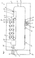
- Fig. 1 shows a schematic side view of an electro-photographic printing apparatus 1.
- the printing apparatus 1 has a housing 3 for mounting different elements therein or thereon, as will be described in more detail herein below.
- a transport arrangement 6 defining a closed loop transport path 7 is provided within the housing 3 within the housing 3 .
- the following are arranged within the housing 3 along the transport path 7: a sheet supply 9, a sheet-aligner 15, a print unit 17, a fuser 19, an inverter 21 and a speed-up/delay unit 22.
- a proofing tray 23 and a sheet output 25 are provided external to the housing. Even though these elements are shown outside of the housing 3, they may also be integrated within the housing 3.
- the transport arrangement 6 may be of any suitable type for transporting a sheet along the transport path 7 through the printing apparatus 1.
- the transport arrangement 6 is formed by a plurality of transport units, with each unit forming a section of the transport path 7. At least one transport unit (not shown) is provided for transporting sheets along a section of the transport path 7 extending from the sheet supply 9 to the aligner 15.
- the aligner 15 forms another transport unit (as will be described in more detail herein below), forming a first alignment section of the transport path 7. Downstream of the aligner 15, a transport unit 28 is provided, which is a designated transport unit for transporting sheets through the print unit 17.
- the transport unit 28 as shown is formed by a belt 30, which is entrained about two rollers 31, at least one of which is driven by an appropriate drive mechanism (not shown).
- the belt 30 is preferably an electrostatic type belt or a suction type belt, which enables securely holding a sheet in a fixed relation to the belt, while transporting the same through the print unit 17.
- the fuser 19 Downstream of the transport unit 28, the fuser 19 has an internal transport unit, forming another section of the transport path. At least one transport unit (not shown) is provided for transporting sheets along another section of the transport path 7 extending from the fuser 19 to inverter 21, which also forms a transport unit.
- An further transport unit (not shown) is arranged downstream of the inverter 21 for transporting sheets from the inverter 21 to the speed-up/delay unit 22, which forms the last transport unit for defining the transport path 7.
- the speed-up/delay unit 22 forms a second alignment section of the transport path 7.
- Downstream of the speed-up/delay unit 22, the at least one transport unit for transporting sheets along the section of the transport path 7 extending from the sheet supply 9 to the aligner 15 is arranged.
- the respective transport units are driven by respective drives and controlled by a controller, for synchronization of a sheet transport throughout the printing apparatus 1. Sheets, which are fed from the sheet supply 9 into the transport path 7 are transported by the individual transport units throughout the printing apparatus 1 along a direction of transport as indicated by arrow A. This direction of transport is also called the "in-track" direction.
- a guide unit 35 Downstream of the fuser 19, a guide unit 35 is provided, for selectively guiding a sheet towards the proofing tray 23, the sheet output 25 or further along the transport path 7.
- the section of the transport path 7 extending between sheet supply 9 to the guide unit 35 may be called a simplex path, while the section extending between guide unit 35 and sheet supply 9 may be called a duplex path, in which sheets which have an image printed on a first side thereof are cycled back to the simplex path while being inverted, to allow printing on the reverse side, as is known in the art.
- the sheet supply 9 has a storage compartment 37 for storing a stack of sheets 38 and a feeder (not shown) for feeding individual sheets 38 into the transport path 7, as indicated by the dashed line B.
- the sheet supply 9 can be of any suitable design for feeding individual sheets 38 into the transport path 7. Even though, Fig. 1 only shows a single sheet supply 9, several sheet supplies, which may for example hold different types of sheets may be provided. These sheet supplies may be arranged in a manner that the sheets are in substance fed at the same position into the transport path 7. Feeding of sheets into the transport path is timed with a frame clock signal, as will be explained in more detail hereinbelow.
- the sheet aligner 15 is arranged downstream of the position where sheets 38 are feed into the transport path by the sheet supply 9.
- the distance along the transport path 7 extending from the position at which the sheet supply 9 feeds sheets 38 to the aligner 15 is larger than several lengths of the sheets 38.
- the sheet aligner 15 may be of any suitable type for aligning sheets 38 in the transport path with respect to an in-track position, i.e. in the direction of transport A and preferably also with respect to skew and with respect to a cross-track position, i.e. at right angle to the direction of transport A.
- the sheet aligner 15 as shown has a pre-alignment section 40 and a final alignment section 41, as is known in the art.
- the pre-alignment section 40 and the final alignment section 41 are capable of providing a predetermined maximum amount of adjustment with respect to the in-track position of a sheet, which amount is limited by the maximum acceleration/deceleration of a sheet transport mechanism while the sheet is within the aligner and is also influenced by the length of the aligner.
- the amount may also be influenced by skew and cross-track misalignment of the sheet which may also be corrected in the aligner.
- the inter frame distances may limit the maximum amount the aligner may adjust the position of the sheet in the in-track direction. The maximum amount of adjustment may thus be calculated on for each sheet entering the aligner or may be fixed for a specific aligner.
- the pre-alignment section 40 has at least one lead edge sensor 42 for sensing a lead edge of a sheet entering the pre-alignment section 40.
- the lead edge sensor 42 is located at the downstream end of the pre-alignment section 40.
- the lead edge sensor 42 is connected to a controller 44, as shown in Fig. 2 , which controller 44 controls several aspects of a printing operation, as will be explained in more detail hereinbelow.
- the lead edge sensor may have two sensors which are spaced a predetermined distance in the cross-track direction, to determine skewing of a sheet upon entering the pre-alignment section.
- the print unit 17 is arranged downstream of the sheet aligner 15 and has one or more electro-photographic print modules 45.
- the printing apparatus 1 as shown in Fig. 1 has five electro-photographic print modules 45 for the application of toner onto a sheet 38. Depending on the printing apparatus 1, a lower or higher number of printing modules 45 may be provided.
- the five print modules 45 each have a photoconductor drum 47, a charge device 49, a selective discharge device 51, a toner application device 53, a transfer roller 55 and a back-up roller 57.
- the photoconductor drum 47 may be of a known type having a photoconducting surface.
- the photoconductor drum 47 may be coupled to a drive mechanism (not shown), for rotating the drum in the direction of arrow C.
- the photoconductor drum 47 is mounted to be freely rotatable about a centered axis of rotation, and rotation of the photoconductor drum 47 is achieved by movement of belt 30, which is frictionally coupled to the photoconductor drum 47 via transfer roller 55.
- the charging device 49 may be any suitable device for homogenously charging the outer surface of the photoconductor drum 47, such as a corona discharge device.
- the selective discharging device 51 is arranged downstream of the charging device 49 in the direction of rotation C of the photoconductor drum 47.
- the selective discharge device 51 may be a device capable of selectively directing light onto the charged surface of the photoconductor drum 47, to thereby selectively locally discharge the surface of the photoconductor drum 47. In so doing, a latent charge image may be formed on the surface of the photoconductor drum 47.
- a typical device used for this purpose is an LED arrangement having a plurality of light emitting diodes arranged in series across the entire width of the photoconductor drum. Each diode addresses one print dot and the spacing between the LED's corresponds to the resolution desired for the printed image.
- the toner application device 53 may be of any suitable design applying a toner to the photoconductor drum 47 in accordance with the latent charge image. It may be of the type having a magnet roller in contact with toner particles and a jump roller. Suitable toner application devices are described e.g. in US4546060 and US 20060177240 .
- the transfer roller 55 is arranged below the photoconductor drum 47 and in contact therewith, such that a transfer nip is formed therebetween.
- the transfer roller 55 preferably has an elastic surface to ensure proper contact across the transfer nip between the photoconductor drum 47 and the transfer roller 55.
- Transfer roller 55 is mounted to be freely rotatable about a centered axis of rotation. During operation of the print module 45, transfer roller 55 is rotated in the direction of arrow D by movement of belt 30, which is frictionally coupled thereto.
- the back-up roller 57 is arranged below the transfer roller 55 and forms another transfer nip therewith, through which the transport belt 30 and a sheet 38 may pass. The back-up roller 57 ensures that the belt 30 or a sheet 38 (if present) is pressed against the transfer roller 57 while being moved through the transfer nip.
- the fuser 19 may be of any suitable type for fusing toner applied by the print modules 45 to a sheet 38, while transporting the sheet along the transport path.
- the fuser 19 may be of a contact type using for example fusing rollers and/or a fuser belt, or of a noncontact type using for example UV-radiation or microwaves for fusing a toner to a sheet.
- the type of fuser 19 is at least partially dependent on the toner used in the print module 45.
- the guide 35 which is arranged downstream of fuser 19, may be of any suitable design for selectively guiding a sheet 38 towards the proofing tray 23, the sheet output 25 or further along the transport path 7.
- Inverter 21 is arranged downstream of the guide 35 along the transport path 7 and upstream of the sheet supply 9.
- the sheet inverter 21 is of any suitable type for inverting a sheet in the transport path, to allow duplex printing of a sheet 38.
- Inverter 21 is preferably of a type, in which the sheet is inverted in such a manner, that the leading edge of the sheet is not changed during the inversion process.
- the speed-up/delay unit 22 may be any suitable transport unit, which provides for locally speeding up/delaying transport of a sheet 38 therethrough in such a manner that at the inlet and outlet ends of the unit, the speed of the sheet is synchronized in substance to the speed of transport of adjacent transport units.
- the speed-up/delay unit 22 is arranged at the end of the duplex path for feeding sheets 38 which are in the duplex path back into the simplex path. Feeding of sheets by the speed-up/delay unit 22 into the simplex path is also timed with a frame clock signal, as will be explained in more detail hereinbelow.
- the proofing tray 23 may be any suitable tray for receiving sheets 32 thereon for proofing purposes, as known in the art.
- the sheet output 25 may again be of any suitable design for receiving printed sheets 32. As shown in Fig. 1 , the sheet output 25 has a tray 60, which may be moved up and down, as indicated by double-headed arrow E, depending on the number of sheets stacked thereon.
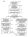
- a series of constant frame clock signals n. n+1, n+2 .... is generated.
- This series of frame clock signals may for example be generated by a frame signal generator which may be incorporated into the control unit 44 shown in Fig. 2 or which may be a separate element.
- the frame clock signals are evenly spaced and each signal defines the beginning and/or the end of a frame at a certain position along the sheet transport path 7.
- a frame virtually defines a desired sheet position along the sheet transport path 7. The position of a frame is not stationary, but virtually moves with a predetermined speed along the sheet transport path 7.
- a virtual print queue will be formed, for example by the controller 44 shown in Fig. 2 , in which images to be printed are assigned to frames in accordance with the frame clock signals. The images to be printed will be assigned to a corresponding frame prior to feeding of a sheet into the frame.
- Block 102 specifically shows the example of feeding a sheet into the sheet transport path at frame clock signal n.
- Feeding of the sheet into the sheet transport path 7 occurs at the beginning of the simplex path described above with respect to Fig. 1 , either via sheet supply 9 or the speed up/delay unit 22.
- the sheet is approximately positioned into the virtual position of a frame along the transport path.
- the sheet is then transported by the respective transport unit along the sheet transport path 7 towards aligner 15, in accordance with block 104.
- the respective sheet transport device is controlled to transport the actual sheet approximately synchronous to the movement of the (virtual) frame along the sheet transport path.
- the lead edge of the sheet Upon entering the aligner 15, the lead edge of the sheet will be detected, as indicated by block 106.
- decision block 108 it is determined whether the sheet 38 is in the desired position defined by the frame within predetermined limits.
- the predetermined limits define a predetermined maximum deviation from the desired sheet position defined by the frame in the in-track direction.
- the predetermined limits may be defined in accordance with the capability of the aligner 15 to speed-up/delay movement of a sheet there through for transferring the sheet to transport unit 28, without interfering with sheets in previous or subsequent frames.
- n+x could signify the generation of a frame clock signal n+x in the series of frame clock signals, wherein x is an integer.
- n could stand for the point in time when the frame clock signal n was generated and x could denote a specific time span.
- the fixed timer after being started will issue a start of frame signal after a fixed time.
- the start of frame signal will then start generation of a latent toner image at print module 45, by first generating a latent charge image on the photoconductor drum 47 of the respective print module 45 followed by transferring the toner thereto according to the latent charge image.
- a fixed timer for each print module (each setting a different predetermined time) for issuing respective start of frame signals may be started at the same time, as obviously the start of frame signals have to be staggered for the different print modules 45.
- the aligner 15 will then be controlled in such a manner that the in-track sheet position of the sheet is aligned in accordance with the start of frame signal.
- This alignment entails transferring the sheet from the aligner 15 to belt 30 of transport unit 28 at a fixed timing with respect to the start of frame signal. By so doing, it may be ensured that the sheet 38 enters the transfer nip between transfer roller 55 and back-up roller 57 of each print module in registration with the latent toner image.
- the latent toner image is printed onto the sheet while being transported through the nip between transfer roller 55 and back-up roller 57, i.e. the latent toner image is transferred in the nip in a registered manner, to the sheet. The image is then fused to the sheet as is known in the art.
- a time shift ⁇ t for starting the fixed timer for issuing the start of frame signal is determined. This time shift is determined in accordance with the deviation of the sheet from its desired position, i.e. the virtual frame position.
- the term ⁇ t defines a time span, and may have a positive or negative value, depending of whether the sheet is to far advanced with respect to the frame position or to far behind.
- block 120 the fixed timer for issuing the start of frame signal is started, at a specified time after generation of frame clock signal n in accordance with which the sheet was fed into the transport path 7. This is indicated in block 120 by the notation n+x+ ⁇ t, wherein the term n+x may have the same meaning as explained above and wherein the term ⁇ t corresponds to the time shift determined in block 118.
- the fixed timer after being started will again issue a start of frame signal after a fixed time.
- the start of frame signal will then start generation of a latent toner image at print module 45, by first generating a latent charge image on the photoconductor drum 47 of the respective print module 45 followed by transferring the toner thereto according to the latent charge image.
- a fixed timer for each print module (each setting a different predetermined time) for issuing respective start of frame signals may be started at the same time, as obviously the start of frame signals have to be staggered for the different print modules 45.
- the aligner 15 will then be controlled in such a manner that the in-track sheet position of the sheet is aligned in accordance with the start of frame signal.
- This alignment entails transferring the sheet from the aligner 15 to belt 30 of transport unit 28 at a fixed timing with respect to the start of frame signal. By so doing, it may be ensured that the sheet 38 enters the transfer nip between transfer roller 55 and back-up roller 57 of each print module in registration with the latent toner image.
- the process then proceeds to block 116 where the latent toner image is printed onto the sheet while being transported through the nip between transfer roller 55 and back-up roller 57, i.e. the latent toner image is transferred in the nip in a registered manner, to the sheet.
- the image is then fused to the sheet as is known in the art.
- the above method of operating the printing apparatus thus uses a specific combination of the known paper-follows-image and image-follows-paper methods.
- This specific combination allows for a shorter transport unit for transporting the sheets through the print unit 17 compared to the transport unit required when using the image-follows-paper method.
- the generation of the start of frame signal respectively the start of a fixed timer for generating the start of frame signal has to be shifted in accordance with the image-follows-paper method of operation described above. Thereafter, however, a paper-follows-image method may again be used by aligning the in-track sheet position in accordance with the start of frame signal.
Landscapes
- Physics & Mathematics (AREA)
- General Physics & Mathematics (AREA)
- Registering Or Overturning Sheets (AREA)
- Handling Of Cut Paper (AREA)
- Accessory Devices And Overall Control Thereof (AREA)
- Control Or Security For Electrophotography (AREA)
- Color Electrophotography (AREA)
Claims (15)
- Verfahren zum Drucken eines Bildes auf ein Blatt in einem Drucker, der mindestens ein Druckmodul und einen Transportmechanismus umfasst, welcher eine Transportbahn bildet zum Transportieren von Blättern am mindestens einen Druckmodul vorbei, mit den Schritten:- Erzeugen einer Reihe konstanter Rahmentaktsignale;- Fördern eines Blattes ungefähr in einen Rahmen entlang der Blatttransportbahn gemäß dem Rahmentaktsignal, wobei der Rahmen eine virtuelle erwünschte Blattposition definiert, die sich mit einer vorbestimmten Geschwindigkeit entlang der Blatttransportbahn bewegt;- Transportieren des Blattes entlang der Blatttransportbahn;- Bestimmen einer spurgenauen Position des Blattes in der Blatttransportbahn und Bestimmen, ob die spurgenaue Position dem Rahmen innerhalb vorbestimmter Grenzen entspricht;- wenn das Blatt dem Rahmen innerhalb vorbestimmter Grenzen entspricht, Bewirken des Starts eines Rahmensignals zu einem vorbestimmten festen Zeitpunkt im Anschluss an die Erzeugung des Rahmentaktsignals, gemäß dem das Blatt in den Rahmen gefördert wurde, wobei der Start des Rahmensignals das Erzeugen eines latenten Tonerbildes im Druckmodul in Gang setzt zur Übertragung des latenten Tonerbildes auf das Blatt;- wenn das Blatt der Rahmenposition innerhalb vorbestimmter Grenzen nicht entspricht, Bewirken des Starts des Rahmensignals zu einem vorgegebenen Zeitpunkt im Anschluss an die Erzeugung des Rahmentaktsignals, gemäß dem das Blatt in den Rahmen gefördert wurde, wobei der vorgegebene Zeitpunkt dem vorbestimmten festen Zeitpunkt entspricht, zu dem eine Zeitverschiebung addiert wird, wobei die Zeitverschiebung auf der Grundlage der Abweichung des aktuellen Blattes bestimmt wird;- spurgenaues Ausrichten des Blattes gemäß dem Beginn des Rahmensignals und Transportieren des so ausgerichteten Blattes durch das Druckmodul in Ausrichtung mit dem latenten Tonerbild, um dieses auf das Blatt zu übertragen.
- Verfahren nach einem der vorhergehenden Ansprüche, worin der Schritt des spurgenauen Ausrichtens des Blattes sich zumindest teilweise zeitlich überlappt mit der Erzeugung des latenten Tonerbildes im Druckmodul.
- Verfahren nach einem der vorhergehenden Ansprüche, worin das Blatt zwischen den Schritten des Förderns des Blattes und des Bestimmens seiner spurgenauen Position über mehrere Blattlängen hinweg entlang der Transportbahn transportiert wird.
- Verfahren nach einem der Ansprüche 1 bis 3, worin das Blatt mittels einer einer Duplexbahn des Druckers zugeordneten Beschleunigungs-/Verzögerungseinheit in die Rahmenposition gefördert wird.
- Verfahren nach einem der vorhergehenden Ansprüche, worin eine Druckwarteschlange, die ein zu druckendes Bild einem Rahmen zuordnet, erzeugt wird, ehe das Blatt in die Rahmenposition gefördert wird.
- Verfahren nach einem der vorhergehenden Ansprüche, worin die Bestimmung der spurgenauen Position des Blattes in einer Ausrichtungseinheit erfolgt, in der das Blatt ausgerichtet wird.
- Verfahren nach Anspruch 6, worin die Ausrichtungseinheit eine Vorabausrichtungseinheit und eine Schlussausrichtungseinheit umfasst und worin die Bestimmung der spurgenauen Position des Blattes zum Zwecke des Bestimmens, ob die spurgenaue Position dem Rahmen innerhalb vorbestimmter Grenzen entspricht, in der Vorabausrichtungseinheit erfolgt.
- Verfahren nach Anspruch 7, worin die Bestimmung der spurgenauen Position an einem stromabwärts gelegenen Ende der Vorabausrichtungseinheit erfolgt.
- Verfahren nach einem der vorhergehenden Ansprüche, worin die Bestimmung der spurgenauen Position durch Erkennen einer Vorlaufkante des Blattes in mindestens einer Position erfolgt.
- Verfahren nach einem der vorhergehenden Ansprüche, worin die Bestimmung der spurgenauen Ausrichtung des Blattes durch Erkennen einer Vorlaufkante des Blattes in mindestens zwei Positionen erfolgt, welche in einer Richtung, die rechtwinklig zur Transportrichtung des Blattes liegt, einen vorbestimmten Abstand voneinander haben.
- Verfahren nach einem der vorhergehenden Ansprüche, worin die vorbestimmten Grenzen durch die Kapazität einer Ausrichtungseinheit definiert sind, um den Transport des Blattes entlang der Transportbahn innerhalb der Ausrichtungseinheit zu beschleunigen/zu verlangsamen.
- Verfahren nach Anspruch 11, worin, um den Transport des Blattes entlang der Transportbahn zu beschleunigen/zu verlangsamen, die Kapazität der Ausrichtungseinheit auf der Grundlage mindestens einer x-Spur oder einer schrägen Fehlausrichtung des Blattes bei seinem Eintritt in die Ausrichtungseinheit berechnet wird.
- Verfahren nach einem der vorhergehenden Ansprüche, worin das Blatt vor oder während seiner spurgenauen Ausrichtung auch bezüglich einer Schrägausrichtung und einer quer zur Spur verlaufenden Ausrichtung ausgerichtet wird.
- Verfahren nach einem der vorhergehenden Ansprüche, worin die Ausrichtung des Blattes in einer Ausrichtungseinheit erfolgt, die das Blatt in eine vorbestimmte Position auf einen Transportmechanismus fördert, damit das Blatt am mindestens einen Printmodul vorbeitransportiert werden kann.
- Verfahren nach Anspruch 14, worin der Transportmechanismus einen Riemen umfasst, der mit einer Fotoleitertrommel des Druckmoduls in Reibungsverbindung steht.
Applications Claiming Priority (1)
| Application Number | Priority Date | Filing Date | Title |
|---|---|---|---|
| PCT/EP2007/011422 WO2009080090A1 (en) | 2007-12-24 | 2007-12-24 | A method for printing an image onto a sheet in a printer |
Publications (2)
| Publication Number | Publication Date |
|---|---|
| EP2225615A1 EP2225615A1 (de) | 2010-09-08 |
| EP2225615B1 true EP2225615B1 (de) | 2011-05-25 |
Family
ID=39759778
Family Applications (1)
| Application Number | Title | Priority Date | Filing Date |
|---|---|---|---|
| EP07866266A Not-in-force EP2225615B1 (de) | 2007-12-24 | 2007-12-24 | Verfahren zum drucken eines bildes auf ein blatt in einem drucker |
Country Status (5)
| Country | Link |
|---|---|
| US (1) | US20120093524A1 (de) |
| EP (1) | EP2225615B1 (de) |
| JP (1) | JP2011508269A (de) |
| AT (1) | ATE511125T1 (de) |
| WO (1) | WO2009080090A1 (de) |
Families Citing this family (1)
| Publication number | Priority date | Publication date | Assignee | Title |
|---|---|---|---|---|
| DE102009058960A1 (de) * | 2009-12-18 | 2011-06-22 | Eastman Kodak Co., N.Y. | Vorrichtung und Verfahren zum Aufbringen und Fixieren eines Tonerbildes auf einem Substrat |
Family Cites Families (13)
| Publication number | Priority date | Publication date | Assignee | Title |
|---|---|---|---|---|
| JP3744728B2 (ja) * | 1999-06-15 | 2006-02-15 | 富士ゼロックス株式会社 | シート搬送装置及びこれを用いた画像形成装置 |
| DE10234629A1 (de) * | 2002-07-29 | 2004-02-19 | Nexpress Solutions Llc | Verfahren und Vorrichtung zur Bereitstellung von Bögen in einer Druckmaschine |
| JP2004107014A (ja) * | 2002-09-18 | 2004-04-08 | Canon Inc | 画像形成装置 |
| JP4474964B2 (ja) * | 2004-03-24 | 2010-06-09 | 富士ゼロックス株式会社 | 画像形成装置、画像検査装置および画像検査方法 |
| JP4432605B2 (ja) * | 2004-05-11 | 2010-03-17 | 富士ゼロックス株式会社 | 電子写真用転写用紙 |
| JP4654638B2 (ja) * | 2004-09-07 | 2011-03-23 | 富士ゼロックス株式会社 | シート姿勢調整装置 |
| JP2006267779A (ja) * | 2005-03-25 | 2006-10-05 | Pfu Ltd | 液体現像電子写真装置 |
| DE102005038324A1 (de) * | 2005-08-11 | 2007-02-15 | Eastman Kodak Co. | Verfahren zum Transportieren von Bögen in einer digitalen Druckmaschine |
| JP2006347732A (ja) * | 2005-06-17 | 2006-12-28 | Fujifilm Holdings Corp | シート状記録媒体供給装置 |
| DE102005038325A1 (de) * | 2005-08-11 | 2007-02-15 | Eastman Kodak Co. | Verfahren zum Kontrollieren von Bögen in einer digitalen Druckmaschine |
| JP2007076250A (ja) * | 2005-09-15 | 2007-03-29 | Ricoh Co Ltd | 画像形成装置、その制御方法及びプログラム |
| JP4724603B2 (ja) * | 2006-05-26 | 2011-07-13 | キヤノン株式会社 | シート搬送装置、画像形成装置及び画像読取装置 |
| JP4961899B2 (ja) * | 2006-08-29 | 2012-06-27 | ブラザー工業株式会社 | 画像形成装置 |
-
2007
- 2007-12-24 US US12/810,357 patent/US20120093524A1/en not_active Abandoned
- 2007-12-24 JP JP2010540030A patent/JP2011508269A/ja active Pending
- 2007-12-24 EP EP07866266A patent/EP2225615B1/de not_active Not-in-force
- 2007-12-24 WO PCT/EP2007/011422 patent/WO2009080090A1/en not_active Ceased
- 2007-12-24 AT AT07866266T patent/ATE511125T1/de not_active IP Right Cessation
Also Published As
| Publication number | Publication date |
|---|---|
| US20120093524A1 (en) | 2012-04-19 |
| ATE511125T1 (de) | 2011-06-15 |
| WO2009080090A1 (en) | 2009-07-02 |
| JP2011508269A (ja) | 2011-03-10 |
| EP2225615A1 (de) | 2010-09-08 |
Similar Documents
| Publication | Publication Date | Title |
|---|---|---|
| JP5201966B2 (ja) | 画像形成装置 | |
| US7525564B2 (en) | Image printing apparatus | |
| US9454120B2 (en) | Image forming apparatus | |
| US20080191413A1 (en) | Paper transport path of image forming apparatus | |
| US6795683B2 (en) | Tandem type printing system | |
| US6826384B2 (en) | Apparatus for a pre-registration speed and timing adjust system | |
| JP4578265B2 (ja) | 画像記録装置およびその制御方法 | |
| JPH11109828A (ja) | 電子写真装置 | |
| US7878497B2 (en) | Image forming apparatus and sheet inserting device | |
| JP2004004781A (ja) | 両面印刷ループを有する印刷装置のシートの搬送の制御方法 | |
| CN105393173B (zh) | 图像形成装置 | |
| US10474078B2 (en) | Image forming apparatus and method of controlling the same | |
| US8622380B2 (en) | Sheet feeding device and image forming apparatus | |
| CN101339379A (zh) | 成像设备 | |
| EP2225615B1 (de) | Verfahren zum drucken eines bildes auf ein blatt in einem drucker | |
| JP5987018B2 (ja) | 画像形成装置 | |
| US20130195531A1 (en) | Image-forming apparatus and method for controlling image-forming apparatus | |
| JP4387378B2 (ja) | 画像形成装置 | |
| JP2006248644A (ja) | 画像形成装置 | |
| US6751437B2 (en) | Image forming apparatus | |
| JP4627049B2 (ja) | 画像形成装置 | |
| US7088947B1 (en) | Post processor inserter speed and timing adjust unit | |
| US20050265761A1 (en) | Electrophotographic printing apparatus and printing system | |
| JPH06156797A (ja) | 画像形成装置の用紙搬送装置 | |
| JP4526510B2 (ja) | 画像形成装置 |
Legal Events
| Date | Code | Title | Description |
|---|---|---|---|
| PUAI | Public reference made under article 153(3) epc to a published international application that has entered the european phase |
Free format text: ORIGINAL CODE: 0009012 |
|
| 17P | Request for examination filed |
Effective date: 20100603 |
|
| AK | Designated contracting states |
Kind code of ref document: A1 Designated state(s): AT BE BG CH CY CZ DE DK EE ES FI FR GB GR HU IE IS IT LI LT LU LV MC MT NL PL PT RO SE SI SK TR |
|
| AX | Request for extension of the european patent |
Extension state: AL BA HR MK RS |
|
| GRAP | Despatch of communication of intention to grant a patent |
Free format text: ORIGINAL CODE: EPIDOSNIGR1 |
|
| DAX | Request for extension of the european patent (deleted) | ||
| GRAS | Grant fee paid |
Free format text: ORIGINAL CODE: EPIDOSNIGR3 |
|
| GRAA | (expected) grant |
Free format text: ORIGINAL CODE: 0009210 |
|
| AK | Designated contracting states |
Kind code of ref document: B1 Designated state(s): AT BE BG CH CY CZ DE DK EE ES FI FR GB GR HU IE IS IT LI LT LU LV MC MT NL PL PT RO SE SI SK TR |
|
| REG | Reference to a national code |
Ref country code: GB Ref legal event code: FG4D |
|
| REG | Reference to a national code |
Ref country code: CH Ref legal event code: EP |
|
| REG | Reference to a national code |
Ref country code: IE Ref legal event code: FG4D |
|
| REG | Reference to a national code |
Ref country code: DE Ref legal event code: R096 Ref document number: 602007014923 Country of ref document: DE Effective date: 20110707 |
|
| REG | Reference to a national code |
Ref country code: NL Ref legal event code: T3 |
|
| PG25 | Lapsed in a contracting state [announced via postgrant information from national office to epo] |
Ref country code: LT Free format text: LAPSE BECAUSE OF FAILURE TO SUBMIT A TRANSLATION OF THE DESCRIPTION OR TO PAY THE FEE WITHIN THE PRESCRIBED TIME-LIMIT Effective date: 20110525 Ref country code: SE Free format text: LAPSE BECAUSE OF FAILURE TO SUBMIT A TRANSLATION OF THE DESCRIPTION OR TO PAY THE FEE WITHIN THE PRESCRIBED TIME-LIMIT Effective date: 20110525 Ref country code: PT Free format text: LAPSE BECAUSE OF FAILURE TO SUBMIT A TRANSLATION OF THE DESCRIPTION OR TO PAY THE FEE WITHIN THE PRESCRIBED TIME-LIMIT Effective date: 20110926 |
|
| PG25 | Lapsed in a contracting state [announced via postgrant information from national office to epo] |
Ref country code: BE Free format text: LAPSE BECAUSE OF FAILURE TO SUBMIT A TRANSLATION OF THE DESCRIPTION OR TO PAY THE FEE WITHIN THE PRESCRIBED TIME-LIMIT Effective date: 20110525 Ref country code: SI Free format text: LAPSE BECAUSE OF FAILURE TO SUBMIT A TRANSLATION OF THE DESCRIPTION OR TO PAY THE FEE WITHIN THE PRESCRIBED TIME-LIMIT Effective date: 20110525 Ref country code: IS Free format text: LAPSE BECAUSE OF FAILURE TO SUBMIT A TRANSLATION OF THE DESCRIPTION OR TO PAY THE FEE WITHIN THE PRESCRIBED TIME-LIMIT Effective date: 20110925 Ref country code: LV Free format text: LAPSE BECAUSE OF FAILURE TO SUBMIT A TRANSLATION OF THE DESCRIPTION OR TO PAY THE FEE WITHIN THE PRESCRIBED TIME-LIMIT Effective date: 20110525 Ref country code: AT Free format text: LAPSE BECAUSE OF FAILURE TO SUBMIT A TRANSLATION OF THE DESCRIPTION OR TO PAY THE FEE WITHIN THE PRESCRIBED TIME-LIMIT Effective date: 20110525 Ref country code: FI Free format text: LAPSE BECAUSE OF FAILURE TO SUBMIT A TRANSLATION OF THE DESCRIPTION OR TO PAY THE FEE WITHIN THE PRESCRIBED TIME-LIMIT Effective date: 20110525 Ref country code: CY Free format text: LAPSE BECAUSE OF FAILURE TO SUBMIT A TRANSLATION OF THE DESCRIPTION OR TO PAY THE FEE WITHIN THE PRESCRIBED TIME-LIMIT Effective date: 20110525 Ref country code: GR Free format text: LAPSE BECAUSE OF FAILURE TO SUBMIT A TRANSLATION OF THE DESCRIPTION OR TO PAY THE FEE WITHIN THE PRESCRIBED TIME-LIMIT Effective date: 20110826 Ref country code: ES Free format text: LAPSE BECAUSE OF FAILURE TO SUBMIT A TRANSLATION OF THE DESCRIPTION OR TO PAY THE FEE WITHIN THE PRESCRIBED TIME-LIMIT Effective date: 20110905 |
|
| PG25 | Lapsed in a contracting state [announced via postgrant information from national office to epo] |
Ref country code: CZ Free format text: LAPSE BECAUSE OF FAILURE TO SUBMIT A TRANSLATION OF THE DESCRIPTION OR TO PAY THE FEE WITHIN THE PRESCRIBED TIME-LIMIT Effective date: 20110525 Ref country code: EE Free format text: LAPSE BECAUSE OF FAILURE TO SUBMIT A TRANSLATION OF THE DESCRIPTION OR TO PAY THE FEE WITHIN THE PRESCRIBED TIME-LIMIT Effective date: 20110525 |
|
| PG25 | Lapsed in a contracting state [announced via postgrant information from national office to epo] |
Ref country code: RO Free format text: LAPSE BECAUSE OF FAILURE TO SUBMIT A TRANSLATION OF THE DESCRIPTION OR TO PAY THE FEE WITHIN THE PRESCRIBED TIME-LIMIT Effective date: 20110525 Ref country code: PL Free format text: LAPSE BECAUSE OF FAILURE TO SUBMIT A TRANSLATION OF THE DESCRIPTION OR TO PAY THE FEE WITHIN THE PRESCRIBED TIME-LIMIT Effective date: 20110525 Ref country code: DK Free format text: LAPSE BECAUSE OF FAILURE TO SUBMIT A TRANSLATION OF THE DESCRIPTION OR TO PAY THE FEE WITHIN THE PRESCRIBED TIME-LIMIT Effective date: 20110525 Ref country code: SK Free format text: LAPSE BECAUSE OF FAILURE TO SUBMIT A TRANSLATION OF THE DESCRIPTION OR TO PAY THE FEE WITHIN THE PRESCRIBED TIME-LIMIT Effective date: 20110525 |
|
| PLBE | No opposition filed within time limit |
Free format text: ORIGINAL CODE: 0009261 |
|
| STAA | Information on the status of an ep patent application or granted ep patent |
Free format text: STATUS: NO OPPOSITION FILED WITHIN TIME LIMIT |
|
| 26N | No opposition filed |
Effective date: 20120228 |
|
| PG25 | Lapsed in a contracting state [announced via postgrant information from national office to epo] |
Ref country code: IT Free format text: LAPSE BECAUSE OF FAILURE TO SUBMIT A TRANSLATION OF THE DESCRIPTION OR TO PAY THE FEE WITHIN THE PRESCRIBED TIME-LIMIT Effective date: 20110525 |
|
| REG | Reference to a national code |
Ref country code: DE Ref legal event code: R097 Ref document number: 602007014923 Country of ref document: DE Effective date: 20120228 |
|
| PG25 | Lapsed in a contracting state [announced via postgrant information from national office to epo] |
Ref country code: MC Free format text: LAPSE BECAUSE OF NON-PAYMENT OF DUE FEES Effective date: 20111231 |
|
| REG | Reference to a national code |
Ref country code: CH Ref legal event code: PL |
|
| REG | Reference to a national code |
Ref country code: IE Ref legal event code: MM4A |
|
| PG25 | Lapsed in a contracting state [announced via postgrant information from national office to epo] |
Ref country code: CH Free format text: LAPSE BECAUSE OF NON-PAYMENT OF DUE FEES Effective date: 20111231 Ref country code: LI Free format text: LAPSE BECAUSE OF NON-PAYMENT OF DUE FEES Effective date: 20111231 Ref country code: IE Free format text: LAPSE BECAUSE OF NON-PAYMENT OF DUE FEES Effective date: 20111224 |
|
| PG25 | Lapsed in a contracting state [announced via postgrant information from national office to epo] |
Ref country code: MT Free format text: LAPSE BECAUSE OF FAILURE TO SUBMIT A TRANSLATION OF THE DESCRIPTION OR TO PAY THE FEE WITHIN THE PRESCRIBED TIME-LIMIT Effective date: 20110525 |
|
| PGFP | Annual fee paid to national office [announced via postgrant information from national office to epo] |
Ref country code: GB Payment date: 20121128 Year of fee payment: 6 |
|
| PGFP | Annual fee paid to national office [announced via postgrant information from national office to epo] |
Ref country code: FR Payment date: 20121219 Year of fee payment: 6 Ref country code: NL Payment date: 20121212 Year of fee payment: 6 |
|
| PGFP | Annual fee paid to national office [announced via postgrant information from national office to epo] |
Ref country code: DE Payment date: 20121221 Year of fee payment: 6 |
|
| PG25 | Lapsed in a contracting state [announced via postgrant information from national office to epo] |
Ref country code: LU Free format text: LAPSE BECAUSE OF NON-PAYMENT OF DUE FEES Effective date: 20111224 |
|
| PG25 | Lapsed in a contracting state [announced via postgrant information from national office to epo] |
Ref country code: BG Free format text: LAPSE BECAUSE OF FAILURE TO SUBMIT A TRANSLATION OF THE DESCRIPTION OR TO PAY THE FEE WITHIN THE PRESCRIBED TIME-LIMIT Effective date: 20110825 |
|
| PG25 | Lapsed in a contracting state [announced via postgrant information from national office to epo] |
Ref country code: TR Free format text: LAPSE BECAUSE OF FAILURE TO SUBMIT A TRANSLATION OF THE DESCRIPTION OR TO PAY THE FEE WITHIN THE PRESCRIBED TIME-LIMIT Effective date: 20110525 |
|
| PG25 | Lapsed in a contracting state [announced via postgrant information from national office to epo] |
Ref country code: HU Free format text: LAPSE BECAUSE OF FAILURE TO SUBMIT A TRANSLATION OF THE DESCRIPTION OR TO PAY THE FEE WITHIN THE PRESCRIBED TIME-LIMIT Effective date: 20110525 |
|
| REG | Reference to a national code |
Ref country code: DE Ref legal event code: R119 Ref document number: 602007014923 Country of ref document: DE |
|
| REG | Reference to a national code |
Ref country code: NL Ref legal event code: V1 Effective date: 20140701 |
|
| GBPC | Gb: european patent ceased through non-payment of renewal fee |
Effective date: 20131224 |
|
| REG | Reference to a national code |
Ref country code: DE Ref legal event code: R119 Ref document number: 602007014923 Country of ref document: DE Effective date: 20140701 |
|
| REG | Reference to a national code |
Ref country code: FR Ref legal event code: ST Effective date: 20140829 |
|
| PG25 | Lapsed in a contracting state [announced via postgrant information from national office to epo] |
Ref country code: DE Free format text: LAPSE BECAUSE OF NON-PAYMENT OF DUE FEES Effective date: 20140701 Ref country code: NL Free format text: LAPSE BECAUSE OF NON-PAYMENT OF DUE FEES Effective date: 20140701 |
|
| PG25 | Lapsed in a contracting state [announced via postgrant information from national office to epo] |
Ref country code: FR Free format text: LAPSE BECAUSE OF NON-PAYMENT OF DUE FEES Effective date: 20131231 Ref country code: GB Free format text: LAPSE BECAUSE OF NON-PAYMENT OF DUE FEES Effective date: 20131224 |