EP2224576B1 - Stator für einen elektronisch kommutierten Gleichstrommotor - Google Patents
Stator für einen elektronisch kommutierten Gleichstrommotor Download PDFInfo
- Publication number
- EP2224576B1 EP2224576B1 EP09015223.2A EP09015223A EP2224576B1 EP 2224576 B1 EP2224576 B1 EP 2224576B1 EP 09015223 A EP09015223 A EP 09015223A EP 2224576 B1 EP2224576 B1 EP 2224576B1
- Authority
- EP
- European Patent Office
- Prior art keywords
- stator
- clamping ring
- stator according
- ring
- poles
- Prior art date
- Legal status (The legal status is an assumption and is not a legal conclusion. Google has not performed a legal analysis and makes no representation as to the accuracy of the status listed.)
- Active
Links
Images



Classifications
-
- H—ELECTRICITY
- H02—GENERATION; CONVERSION OR DISTRIBUTION OF ELECTRIC POWER
- H02K—DYNAMO-ELECTRIC MACHINES
- H02K1/00—Details of the magnetic circuit
- H02K1/06—Details of the magnetic circuit characterised by the shape, form or construction
- H02K1/12—Stationary parts of the magnetic circuit
- H02K1/14—Stator cores with salient poles
- H02K1/146—Stator cores with salient poles consisting of a generally annular yoke with salient poles
- H02K1/148—Sectional cores
-
- H—ELECTRICITY
- H02—GENERATION; CONVERSION OR DISTRIBUTION OF ELECTRIC POWER
- H02K—DYNAMO-ELECTRIC MACHINES
- H02K1/00—Details of the magnetic circuit
- H02K1/06—Details of the magnetic circuit characterised by the shape, form or construction
- H02K1/12—Stationary parts of the magnetic circuit
- H02K1/18—Means for mounting or fastening magnetic stationary parts on to, or to, the stator structures
-
- H—ELECTRICITY
- H02—GENERATION; CONVERSION OR DISTRIBUTION OF ELECTRIC POWER
- H02K—DYNAMO-ELECTRIC MACHINES
- H02K15/00—Processes or apparatus specially adapted for manufacturing, assembling, maintaining or repairing of dynamo-electric machines
- H02K15/02—Processes or apparatus specially adapted for manufacturing, assembling, maintaining or repairing of dynamo-electric machines of stator or rotor bodies
- H02K15/028—Fastening stator or rotor bodies to casings, supports, shafts or hubs
-
- H—ELECTRICITY
- H02—GENERATION; CONVERSION OR DISTRIBUTION OF ELECTRIC POWER
- H02K—DYNAMO-ELECTRIC MACHINES
- H02K3/00—Details of windings
- H02K3/04—Windings characterised by the conductor shape, form or construction, e.g. with bar conductors
- H02K3/28—Layout of windings or of connections between windings
Definitions
- the invention relates to a stator (10) for an electronically commutated direct current motor, with a plurality of stator poles (1) designed as individual parts, consisting of a pole core (25), pole pieces (26) and yoke sections (27), the yoke sections (27) of the stator poles (1) have interlocking profiles against which they abut one another in such a way that they form a hollow cylindrical yoke (35), the pole cores (25) connecting radially inward to the yoke sections (27) such that the individual stator poles (1 ) are each provided with insulation and a winding and that the wound stator poles (1) are held together by a holding part that does not serve as a motor housing.
- a generic stator is known in which two plastic holding parts are provided with axially projecting pins which engage in holes in the yoke sections of the stator poles and thereby connect them to one another.
- These plastic holding parts can only serve as adjustment means for the stator poles, but cannot brace them sufficiently.
- To brace the poles they must be pressed into the motor housing in a known manner. It is known, for example, to mount the motor housing by shrinking onto the stator poles or to provide the stator poles with yielding projections in order to enable pressing into the motor housing.
- all of these known methods can be carried out only with great effort.
- a stator for an electronically commutated DC motor with a plurality of stator poles formed as individual parts, consisting of a pole core, pole pieces and yoke sections, the yoke sections of the stator poles having intermeshing profiles, on which the yoke sections rest against one another in such a way that they form a hollow cylindrical yoke , wherein the pole cores connect radially inward to the yoke sections, that the individual stator poles are each provided with insulation and a winding and that the wound stator poles are held together by a holding part, characterized in that the holding part metallic clamping ring is known, which is placed under prestress around the entire circumference of the hollow cylindrical yoke and braces the stator poles together.
- the WO 2007/107131 A1 discloses a stator formed from a plurality of interlocking stator poles, which are held together by a tension ring.
- the JP 2007 259620 A discloses a stator of a motor with several individual stator poles, which are held together by means of a clamping ring.
- the object of the present invention is to present a stator for an electronically commutated direct current motor which can be assembled simply and reliably and which facilitates the assembly of the stator in the motor housing.
- the holding part is a metallic tension ring, which is placed under prestress around the entire circumference of the hollow cylindrical yoke, the stator poles can be easily clamped together, the tension ring is neither required as a yoke nor as a motor housing element and can therefore be designed and optimized for its primary task will. Since the stator no longer necessarily has to be clamped to the motor housing and the clamping ring and the motor housing do not have to serve as a yoke element, there is greater freedom of design also with regard to the tightness of the housing and the weight.
- the clamping ring 4 is also in one piece with screw eyes 8 which are angled at right angles and extend radially outwards.
- Fig. 1 shows a stator pole 1, consisting of a pole core 25, pole pieces 26, yoke sections 27, which have mutually matching profiles in the form of a concave profile 28 and a convex profile 29, a trench-shaped recess 30 from which a projection 23 emerges.
- the projection 23 does not encompass the entire length of the stator pole 1, but is arranged in the center and leaves a receiving space at both ends.
- the stator poles can be designed both as punch-packaged parts and as powder-pressed parts.
- Fig. 2 shows an end cap 3, with a receiving space 24 for receiving the stator pole on one side, in addition the end cap 3 comprises receiving areas for a winding head of a stator winding and slots 19 for fixing winding ends of the stator winding.
- Fig. 3 shows a further end cap 2, which is designed without slots, but otherwise designed as the end cap 3.
- Fig. 4 shows the end cap 2 from a different perspective.
- Fig. 5 represents a stator pole 1 with end caps 2, 3 mounted on its opposite end faces. End caps of this type are known and are used in a variety of configurations.
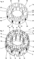
- Fig. 6 shows for illustration a stator ring composed of nine stator poles without end caps and without winding. In the form shown, the stator is not in any assembly step because the end caps and the winding are first applied.
- Fig. 7 shows the stator Fig. 6 with fitted end caps 2 and 3.
- the winding is omitted for the sake of simplicity.
- the end caps do not extend into a radial area between the stator pole or pole piece and a rotor, not shown here.
- All end caps 3 with slots 19 are arranged on the same side of the stator poles and all end caps 2 without slots on the opposite side.
- Fig. 8 shows the arrangement according to Fig. 7 with additionally mounted clamping ring 4, which serves as a holding part for the stator poles.
- the clamping ring 4 is shown as an individual part.
- the clamping ring is rolled from a stamped sheet metal strip and attached to the Ends mechanically connected.
- the connection point 13 is designed as a caulked button.
- the clamping ring consists essentially of two ring areas 36 which are connected to one another via bridges 18.
- the bridges 18 are slightly radially inwardly deformed in their center, so that there is a radial preload which ensures a play-free connection between the tension ring and the stator poles after assembly.
- connection between the two ring areas 36 is partially interrupted by recesses 37, so that webs 14 remain and H-shaped connection areas remain between the ring areas 36.
- the ring regions 36 are deformed radially inwards on the peripheral sections relative to the webs 14.
- the axially inwardly deformed areas serve as axial securing webs 11 for axial fixing to the projections 23 of the stator poles 1.
- the clamping ring 4 is also in one piece with screw-on eyelets 8 which are angled at right angles and extend radially outward.
- the screw eyes 8 are arranged in the peripheral sections in which bridges 18 or webs 14 are present between the ring regions 36.
- the screw-on eyelets 8 serve to fasten the assembled stator in a motor housing.
- adjustment openings 16 are provided parallel to the screw-on eyelets 8, which are necessary for an exact position assignment of the stator in the motor housing.
- the clamping ring 4 comprises a star point connection 9 which projects axially. The clamping ring can thus serve as an additional function as an electrical star point connection 9 for the stator winding.
- Fig. 9 shows the arrangement according to Fig. 8 with an additional insulating ring 5, which is pushed over the clamping ring 4 and fixed to it.
- the insulating ring 5 is shown as a single part.
- the insulating ring has a reduced-diameter area on its inner circumference which forms a stop ring 38.
- the insulating ring is interrupted several times in order to achieve radial flexibility for its mounting on the stator.
- Snap hooks 17 are formed on the inner circumference of a plurality of tines remaining due to the interruptions.
- the area between the snap hooks and the stop ring 38 is provided as a receiving space for the clamping ring 4.
- adjustment pins 15 are formed, which can be inserted into the adjustment openings 16 of the clamping ring and thus enable precise alignment.
- adjustment pins 21 are formed, which are used to adjust a circuit board.
- the insulating ring 5 also has slots 20 for receiving the winding ends of the stator windings.
- Receptacles 22 for insulation displacement contacts which are fastened on the printed circuit board, adjoin the inner regions of the slots 20.
- the slots 20 are aligned with the slots 19 of the end caps 3 and are accordingly mounted on the same side of the stator poles.
- Fig. 11 shows the simplified stator 10 without end caps and winding with the tension ring 4.
- the axial securing webs 11 take up the space of recesses 30 and hold the tension ring 4 axially on the projections 23 on the stator poles.
- Fig. 12 shows another perspective of the stator according to Fig. 11 , with one pole omitted for better illustration. It can be clearly seen that the web 14 maintains the circumferential contour of the clamping ring 4 while the axial securing webs 11 are deformed inwards. In order to obtain this shape, the axial securing webs 11 must be stretched in relation to the original shape.
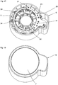
- Fig. 15 shows the stator 10, which is mounted axially in the motor housing 6 via screws 34.
- the stator is shown without an insulating ring.
- Connector pins 32 are mounted in a region of the motor housing 6 that adjoins the stator radially.
- Fig. 16 shows the arrangement Fig. 15 with insulating ring 5, insulation displacement contacts 31 being shown, which in this assembly state are actually not provided without a printed circuit board.
- Fig. 17 shows the arrangement Fig. 16 with a printed circuit board 33, which are inserted on the adjusting pins 21 of the insulating ring 5 and interconnect the stator windings and connects them to the connector pins 32.
- Fig. 18 shows the closed motor housing 6 with a housing cover 7.
- Reference list 1 Stator pole 34 Screws 2nd End cap without slit 35
- Conclusion 3rd Slotted end cap 36 Ring area 4th Tension ring 37
- Recess 5 Insulating ring 38
- Stop ring 6 Motor housing 7 Housing cover 8th Screw-on eye 9
- Neutral point connection 10th stator 11 Axial securing web 12th breakthrough 13 Liaison 14 web 15
- Adjustment pin for clamping ring 16 Adjustment breakthrough 17th Snap hook 18th bridge 19th Slit in the end cap 20th Slit in the insulating ring 21
- Adjustment pin for circuit board 22 Holder for insulation displacement contact 23 head Start 24th Recording room for pole 25th Polkern 26 Pole piece 27 Inference section 28 concave profile 29 convex profile 30th Recess 31 Insulation displacement contact 32 Connector pin 33 Circuit board
Landscapes
- Engineering & Computer Science (AREA)
- Power Engineering (AREA)
- Manufacturing & Machinery (AREA)
- Insulation, Fastening Of Motor, Generator Windings (AREA)
Description
- Die Erfindung betrifft einen Stator (10) für einen elektronisch kommutierten Gleichstrommotor, mit einer Mehrzahl von als Einzelteile ausgebildeten Statorpolen (1), bestehend aus einem Polkern (25), Polschuhen (26) und Rückschlussabschnitten (27), wobei die Rückschlussabschnitte (27) der Statorpole (1) ineinandergreifende Profilierungen aufweisen an welchen sie so einander anliegen, dass sie miteinander einen hohlzylindrischen Rückschluss (35) bilden, wobei die Polkerne (25) radial nach innen gerichtet an die Rückschlussabschnitte (27) anschließen, dass die einzelnen Statorpole (1) jeweils mit einer Isolierung und einer Wicklung versehen sind und dass die bewickelten Statorpole (1) durch ein nicht als Motorgehäuse dienendes Halteteil zusammengehalten werden.
- Aus der
DE 10 2005 051 506 A1 ist ein gattungsgemäßer Stator bekannt, bei dem zwei aus Kunststoff bestehende Halteteile mit axial vorspringenden Stiften vorgesehen sind, die in Löcher der Rückschlussabschnitte der Statorpole eingreifen und diese dadurch miteinander verbinden. Diese Kunststoffhalteteile können lediglich als Justagemittel für die Statorpole dienen, diese aber nicht ausreichend miteinander verspannen. Für die Verspannung der Pole müssen diese nach bekannter Weise im Motorgehäuse eingepresst werden. Es ist beispielhaft bekannt Motorgehäuse durch Aufschrumpfen auf die Statorpole zu montieren oder Statorpole mit nachgebenden Vorsprüngen zu versehen um ein Einpressen in das Motorgehäuse zu ermöglichen. Alle diese bekannten Verfahren lassen sich jedoch nur sehr aufwändig durchführen. - Aus der nächstliegenden
US 2010 / 007 236 ist ein Stator für einen elektronisch kommutierten Gleichstrommotor mit einer Mehrzahl von als Einzelteile ausgebildeten Statorpolen, bestehend aus einem Polkern, Polschuhen und Rückschlussabschnitten, wobei die Rückschlussabschnitte der Statorpole ineinandergreifende Profilierungen aufweisen, an welchen die Rückschlussabschnitte so einander anliegen, dass sie miteinander einen hohlzylindrischen Rückschluss bilden, wobei die Polkerne radial nach innen gerichtet an die Rückschlussabschnitte anschließen, dass die einzelnen Statorpole jeweils mit einer Isolierung und einer Wicklung versehen sind und dass die bewickelten Statorpole durch ein Halteteil zusammengehalten werden, dadurch gekennzeichnet, dass das Halteteil ein metallischer Spannring ist, der unter Vorspannung um den gesamten Umfang des hohlzylindrischen Rückschluss herum gelegt ist und die Statorpole miteinander verspannt, bekannt. - Die
WO 2007 / 107131 A1 offenbart einen Stator, gebildet aus mehreren ineinandergreifenden Statorpolen, die über einen Spannring zusammengehalten sind. - Aus der
JP 2008 278653 A - Die
JP 2007 259620 A - Aus der
JP 2008 086172 A - Aufgabe der vorliegenden Erfindung ist es einen Stator für einen elektronisch kommutierten Gleichstrommotor darzustellen, der einfach und zuverlässig montiert werden kann und der die Montage des Stators im Motorgehäuse erleichtert.
- Diese Aufgabe wird erfindungsgemäß durch das Kennzeichen des Anspruchs 1 gelöst. Da das Halteteil ein metallischer Spannring ist, der unter Vorspannung um den gesamten Umfang des hohlzylindrischen Rückschlusses herum gelegt ist, können die Statorpole einfach miteinander verspannt werden, dabei wird der Spannring weder als Rückschlussnoch als Motorgehäuseelement benötigt und kann daher für seine primäre Aufgabe ausgelegt und optimiert werden. Da der Stator nicht mehr notwendigerweise mit dem Motorgehäuse verspannt werden muss und der Spannring sowie auch das Motorgehäuse nicht als Rückschlusselement dienen muss, besteht eine größere Gestaltungsfreiheit auch hinsichtlich der Gehäusedichtigkeit und des Gewichts. Der Spannring 4 ist darüber hinaus mit Anschraubösen 8 einstückig, die rechtwinklig abgewinkelt sind und sich radial nach außen erstrecken.
- Weiterbildungen und vorteilhafte Ausgestaltungen der Erfindung werden in den Unteransprüchen dargestellt.
- Ein Ausführungsbeispiel der Erfindung wird nachfolgend anhand der Zeichnung näher erläutert. Es zeigen:
- Fig. 1
- einen Statorpol,
- Fig. 2
- eine erste Endkappe mit Schlitz,
- Fig. 3
- eine zweite Endkappe ohne Schlitz,
- Fig. 4
- die zweite Endkappe aus einer anderen Perspektive,
- Fig. 5
- einen Statorpol mit montierten Endkappen,
- Fig. 6
- zu einem Stator zusammengefügte Statorpole,
- Fig. 7
- zu einem Stator zusammengefügte Statorpole mit montierten Endkappen,
- Fig. 8
- der Stator aus
Fig. 7 mit einem Spannring, - Fig. 9
- der Stator aus
Fig. 8 mit einem Isolierring, - Fig. 10
- der Spannring als Einzelteil,
- Fig. 11
- der montierte Spannring mit Stator ohne Endkappen,
- Fig. 12
- der Stator nach
Fig. 11 aus einer anderen Perspektive mit einem weggelassenen Pol, - Fig. 13
- den Isolierring als Einzelteil,
- Fig. 14
- den Isolierring aus einer anderen Perspektive,
- Fig. 15
- den Stator in einem Motorgehäuse angeordnet ohne Isolierring,
- Fig. 16
- den Stator nach
Fig. 15 mit Isolierring, - Fig. 17
- den Stator nach
Fig. 16 mit einer Leiterplatte und - Fig. 18
- den Stator nach
Fig. 17 mit geschlossenem Motorgehäuse. -
Fig. 1 zeigt einen Statorpol 1, bestehend aus einem Polkern 25, Polschuhen 26, Rückschlussabschnitten 27, die ineinander passende Profilierungen in Form eines konkaven Profils 28 und eines konvexen Profils 29 aufweisen, einer grabenförmigen Ausnehmung 30 aus der ein Vorsprung 23 hervortritt. Der Vorsprung 23 umfasst nicht die gesamte Länge des Statorpols 1, sondern ist mittig angeordnet und belässt an beiden Enden einen Aufnahmeraum. Die Statorpole können sowohl als stanzpaketierte Teile als auch als pulvergepresste Teile ausgeführt sein. -
Fig. 2 zeigt eine Endkappe 3, mit einem Aufnahmeraum 24 zur einseitigen Aufnahme des Statorpols, zusätzliche umfasst die Endkappe 3 Aufnahmebereiche für einen Wickelkopf einer Statorwicklung und Schlitze 19 zur Fixierung von Wicklungsenden der Statorwicklung. -
Fig. 3 zeigt eine weitere Endkappe 2, die ohne Schlitze ausgeführt ist, im übrigen aber wie die Endkappe 3 ausgebildet ist. -
Fig. 4 zeigt die Endkappe 2 aus einer anderen Perspektive. -
Fig. 5 stellt einen Statorpol 1 mit auf dessen gegenüberliegenden Stirnseiten montierten Endkappen 2, 3 dar. Endkappen dieser Art sind bekannt und werden in vielfältiger Ausgestaltung verwendet. -
Fig. 6 zeigt zur Veranschaulichung einen aus neun Statorpolen zusammengesetzten Statorring ohne Endkappen und ohne Wicklung. In der dargestellten Form liegt der Stator in keinem Montageschritt vor, weil zunächst die Endkappen und die Wicklung aufgebracht werden. -
Fig. 7 zeigt den Stator ausFig. 6 mit montierten Endkappen 2 und 3. Die Wicklung ist der Einfachheit halber weggelassen. Die Endkappen erstrecken sich nicht in einen radialen Bereich zwischen Statorpol bzw. Polschuh und einem hier nicht dargestellten Rotor. Alle Endkappen 3 mit Schlitzen 19 sind auf der gleichen Seite der Statorpole angeordnet und alle Endkappen 2 ohne Schlitze auf der gegenüberliegenden Seite. -
Fig. 8 zeigt die Anordnung gemäßFig. 7 mit zusätzlich montiertem Spannring 4, der als Halteteil für die Statorpole dient. InFig. 10 ist der Spannring 4 als Einzelteil dargestellt. Der Spannring ist im gezeigten Beispiel aus einem gestanzten Blechstreifen gerollt und an den Enden mechanisch verbunden. Die Verbindungsstelle 13 ist als verstemmter Knopf ausgebildet. Der Spannring besteht im wesentlichen aus zwei Ringbereichen 36, die über Brücken 18 miteinander verbunden sind. Die Brücken 18 sind in ihrer Mitte geringfügig radial nach innen verformt, so dass eine radiale Vorspannung gegeben ist, die nach der Montage eine spielfreie Verbindung zwischen dem Spannring und den Statorpolen sicherstellt. An drei Stellen ist die Verbindung zwischen den beiden Ringbereichen 36 durch Aussparungen 37 partiell unterbrochen, so dass Stege 14 verbleiben und H-förmige Verbindungsbereiche zwischen den Ringbereichen 36 verbleiben. Die Ringbereiche 36 sind auf den Umfangsabschnitten gegenüber den Stegen 14 radial nach innen verformt. Die axial nach innen verformten Bereiche dienen als Axialsicherungsstege 11 zur axialen Fixierung an den Vorsprüngen 23 der Statorpole 1. Der Spannring 4 ist darüber hinaus mit Anschraubösen 8 einstückig, die rechtwinklig abgewinkelt sind und sich radial nach außen erstrecken. Die Anschraubösen 8 sind in den Umfangsabschnitten angeordnet, in denen Brücken 18 oder Stege 14 zwischen den Ringbereichen 36 vorhanden sind. Die Anschraubösen 8 dienen als Befestigungsmöglichkeit des montierten Stators in einem Motorgehäuse. Weiter sind Justagedurchbrüche 16 parallel zu den Anschraubösen 8 vorgesehen, die für eine genaue Lagezuordnung des Stators im Motorgehäuse notwendig sind. Der Spannring 4 umfasst einen Sternpunktanschluss 9 der axial vorspringt. Der Spannring kann somit als Zusatzfunktion als elektrischer Sternpunktanschluss 9 für die Statorwicklung dienen. -
Fig. 9 zeigt die Anordnung gemäßFig. 8 mit zusätzlich montiertem Isolierring 5, der über den Spannring 4 geschoben und daran fixiert ist. In denFig. 13 und 14 ist der Isolierring 5 als Einzelteil dargestellt. Der Isolierring weist an einem ersten axialen Ende an seinem Innenumfang einen durchmesserreduzierten Bereich auf, der einen Anschlagring 38 bildet. An dem gegenüberliegenden axialen Ende ist der Isolierring mehrfach unterbrochen, um eine radiale Nachgiebigkeit für seine Montage auf den Stator zu erreichen. An mehreren durch die Unterbrechungen verbleibenden Zacken sind am Innenumfang Schnapphaken 17 angeformt. Der Bereich zwischen den Schnapphaken und dem Anschlagring 38 ist als Aufnahmeraum für den Spannring 4 vorgesehen. Mit dem Isolierring 5 sind Justagestifte 15 mitgeformt, die in die Justagedurchbrüche 16 des Spannrings fügbar sind und somit eine genaue Ausrichtung ermöglichen. Auf der axial gegenüberliegenden Seite sind Justagestifte 21 mitgeformt, die zur Justage einer Leiterplatte dienen. Der Isolierring 5 weist weiter Schlitze 20 zur Aufnahme der Wicklungsenden der Statorwicklungen auf. An die Innenbereiche der Schlitze 20 schließen Aufnahmen 22 für Schneidklemmkontakte an, die auf der Leiterplatte befestigt sind. Die Schlitze 20 fluchten mit den Schlitzen 19 der Endkappen 3 und sind entsprechend auf der gleichen Seite der Statorpole montiert. -
Fig. 11 zeigt den vereinfacht dargestellten Stator 10 ohne Endkappen und Wicklung mit montiertem Spannring 4. Die Axialsicherungsstege 11 nehmen den Raum von Ausnehmungen 30 ein und halten den Spannring 4 axial an den Vorsprüngen 23 an den Statorpolen fest. -
Fig. 12 zeigt eine andere Perspektive des Stators gemäßFig. 11 , wobei ein Pol zur besseren Veranschaulichung weggelassen ist. Deutlich zu erkennen ist, dass der Steg 14 die Umfangskontur des Spannrings 4 beibehält während die Axialsicherungsstege 11 nach innen verformt sind. Um diese Form zu erhalten müssen die Axialsicherungsstege 11 gegenüber der Ursprünglichen Form gestreckt sein. -
Fig. 15 zeigt den Stator 10, der im Motorgehäuse 6 über Schrauben 34 axial montiert ist. Hierbei ist der Stator ohne Isolierring dargestellt. In einem radial an den Stator anschließenden Bereich des Motorgehäuses 6 sind Steckerstifte 32 montiert. -
Fig. 16 zeigt die Anordnung ausFig. 15 mit Isolierring 5, wobei Schneidklemmkontakte 31 dargestellt sind, die in diesem Montagezustand tatsächlich nicht ohne Leiterplatte vorgesehen sind. -
Fig. 17 zeigt die Anordnung aufFig. 16 mit einer Leiterplatte 33, die auf den Justierstiften 21 des Isolierrings 5 gesteckt sind und die Statorwicklungen miteinander verschalten und mit den Steckerstiften 32 verbindet. -
Fig. 18 zeigt die das geschlossene Motorgehäuse 6 mit einem Gehäusedeckel 7.Bezugszeichenliste 1 Statorpol 34 Schrauben 2 Endkappe ohne Schlitz 35 Rückschluss 3 Endkappe mit Schlitz 36 Ringbereich 4 Spannring 37 Aussparung 5 Isolierring 38 Anschlagring 6 Motorgehäuse 7 Gehäusedeckel 8 Anschrauböse 9 Sternpunktanschluss 10 Stator 11 Axialsicherungssteg 12 Durchbruch 13 Verbindungsstelle 14 Steg 15 Justagestift für Spannring 16 Justagedurchbruch 17 Schnapphaken 18 Brücke 19 Schlitz in Endkappe 20 Schlitz im Isolierring 21 Justagestift für Leiterplatte 22 Aufnahme für Schneidklemmkontakt 23 Vorsprung 24 Aufnahmeraum für Pol 25 Polkern 26 Polschuh 27 Rückschlussabschnitt 28 konkaves Profil 29 konvexes Profil 30 Ausnehmung 31 Schneidklemmkontakt 32 Steckerstift 33 Leiterplatte
Claims (13)
- Stator (10) für einen elektronisch kommutierten Gleichstrommotor, mit einer Mehrzahl von als Einzelteile ausgebildeten Statorpolen (1), bestehend aus einem Polkern (25), Polschuhen (26) und Rückschlussabschnitten (27), wobei die Rückschlussabschnitte (27) der Statorpole (1) ineinandergreifende Profilierungen aufweisen an welchen die Rückschlussabschnitte (27) so einander anliegen, dass sie miteinander einen hohlzylindrischen Rückschluss (35) bilden, wobei die Polkerne (25) radial nach innen gerichtet an die Rückschlussabschnitte (27) anschließen, dass die einzelnen Statorpole (1) jeweils mit einer Isolierung und einer Wicklung versehen sind und dass die bewickelten Statorpole (1) durch ein Halteteil zusammengehalten werden und das Halteteil ein metallischer Spannring (4) ist, der unter Vorspannung um den gesamten Umfang des hohlzylindrischen Rückschlusses (35) herum gelegt ist und die Statorpole (1) miteinander verspannt, dadurch gekennzeichnet, dass der Spannring (4) mit Anschraubösen (8) einstückig ist, die an einen Ringbereich (36) anschließen und rechtwinklig abgebogen sind.
- Stator nach Anspruch 1, dadurch gekennzeichnet, dass der Spannring (4) in seiner Grundform ein Hohlzylinder mit einer Vielzahl von Durchbrüchen (12) ist, wobei Brücken (18) und Stege (14) verbleiben, welche zwei vollumfängliche Ringbereiche (36) miteinander verbinden.
- Stator nach Anspruch 2, dadurch gekennzeichnet, dass die Ringbereiche (36) an mehreren Stellen radial nach innen verformt sind, so dass sie Axialsicherungsmittel (11) bilden.
- Stator nach Anspruch 3, dadurch gekennzeichnet, dass die Axialsicherungsmittel (11) im Bereich von Stegen (14) angeordnet sind, die durch Aussparungen (37) von den Axialsicherungsmitteln (11) getrennt sind und die Ringbereiche (36) miteinander verbinden.
- Stator nach Anspruch 3 oder 4, dadurch gekennzeichnet, dass die Axialsicherungsmittel (11) in Ausnehmungen (30) des hohlzylindrischen Rückschlusses (35) radial nach innen eingreifen wobei in einem mittleren Abschnitt der Ausnehmungen (30) sich radial nach außen erstreckende Vorsprünge (23) an den Axialsicherungsmitteln (11) anliegen.
- Stator nach Anspruch 2, 3, 4 oder 5, dadurch gekennzeichnet, dass die Brücken (18) nach innen auf den hohlzylindrischen Rückschluss (35) vorgespannt sind.
- Stator nach Anspruch 1, 2, 3 oder 4, dadurch gekennzeichnet, dass das Halteteil zumindest eine elektrische Verbindung zum Herstellen der Verschaltung der Wicklungen des Stators (10) umfasst.
- Stator nach Anspruch 2, 3, 4 oder 7, dadurch gekennzeichnet, dass das Halteteil, in Form des Spannrings (4), mit einem Sternpunktanschluss (9) einstückig ist, der axial an einem Ringbereich (36) anschließt und über die Stirnseite der Statorpole (1) vorspringt.
- Stator nach Anspruch-1, dadurch gekennzeichnet, dass der Stator (10) über den Spannring (4) mit einem Motorgehäuse (6) verschraubt, verstemmt, vernietet oder ultraschallverschweißt ist.
- Stator nach zumindest einem der vorangehenden Ansprüche, dadurch gekennzeichnet, dass der Spannring (4) aus einem ursprünglich ebenen Blechstreifen besteht, deren Enden nach einem Biegeprozess miteinander verbunden sind und eine Verbindungsstelle (13) bilden.
- Stator nach zumindest einem der vorangehenden Ansprüche, dadurch gekennzeichnet, dass der Spannring (4) mit einem Isolierring (5) verbunden ist, der Schlitze (20) zur Aufnahme von Wicklungsenden und Aufnahmen (22) für Schneidklemmkontakte (31)aufweist.
- Stator nach Anspruch 11, dadurch gekennzeichnet, dass der Isolierring (5) mit Rastnasen versehen ist, die an einer Kante eines Ringbereichs (36) des Spannrings (4) verriegelt sind.
- Stator nach Anspruch 11 oder 12, dadurch gekennzeichnet, dass der Isolierring (5) mit einer Leiterplatte (33) mechanisch verbunden ist, welche die Wicklungsenden mit dem Sternpunktanschluss (9) und Steckerstiften (32) verschaltet.
Applications Claiming Priority (1)
| Application Number | Priority Date | Filing Date | Title |
|---|---|---|---|
| DE102009010782A DE102009010782A1 (de) | 2009-02-26 | 2009-02-26 | Stator für einen elektronisch kommutierten Gleichstrommotor |
Publications (3)
| Publication Number | Publication Date |
|---|---|
| EP2224576A2 EP2224576A2 (de) | 2010-09-01 |
| EP2224576A3 EP2224576A3 (de) | 2016-09-07 |
| EP2224576B1 true EP2224576B1 (de) | 2020-04-01 |
Family
ID=42243025
Family Applications (1)
| Application Number | Title | Priority Date | Filing Date |
|---|---|---|---|
| EP09015223.2A Active EP2224576B1 (de) | 2009-02-26 | 2009-12-09 | Stator für einen elektronisch kommutierten Gleichstrommotor |
Country Status (3)
| Country | Link |
|---|---|
| US (1) | US8198780B2 (de) |
| EP (1) | EP2224576B1 (de) |
| DE (1) | DE102009010782A1 (de) |
Families Citing this family (9)
| Publication number | Priority date | Publication date | Assignee | Title |
|---|---|---|---|---|
| DE102010056120A1 (de) * | 2010-12-20 | 2012-07-05 | C. & E. Fein Gmbh | Verschaltungseinrichtung für einen Elektromotor |
| US9343930B2 (en) | 2012-05-25 | 2016-05-17 | Baldor Electric Company | Segmented stator assembly |
| DE102012020547A1 (de) * | 2012-10-19 | 2014-04-24 | Sew-Eurodrive Gmbh & Co Kg | Elektromotor mit Stator |
| CN105324915B (zh) * | 2013-07-19 | 2017-11-17 | 本田技研工业株式会社 | 定子 |
| US10177633B2 (en) | 2014-12-23 | 2019-01-08 | Abb Schweiz Ag | Multiphase fractional slot concentrated winding machine with end mounted detachable or integrated multiphase series converter circuit |
| CN108702043B (zh) * | 2016-02-29 | 2021-02-02 | 株式会社安川电机 | 旋转电机和旋转电机的制造方法 |
| WO2018092208A1 (ja) | 2016-11-16 | 2018-05-24 | 三菱電機株式会社 | 回転電機の保護カバー |
| JP2020156147A (ja) * | 2019-03-18 | 2020-09-24 | 株式会社デンソー | ブラシレスモータ |
| JP6900988B2 (ja) * | 2019-10-15 | 2021-07-14 | ダイキン工業株式会社 | ロータリ圧縮機 |
Family Cites Families (11)
| Publication number | Priority date | Publication date | Assignee | Title |
|---|---|---|---|---|
| US4425523A (en) * | 1982-06-04 | 1984-01-10 | Westinghouse Electric Corp. | Core spring support system for a dynamoelectric machine |
| US6941644B2 (en) * | 1999-09-27 | 2005-09-13 | Reliance Electric Technologies, Llc | Method for winding segments of a segmented wound member of an electromechanical device |
| DE10026003A1 (de) * | 2000-05-25 | 2001-12-06 | Bosch Gmbh Robert | Stator |
| JP3661589B2 (ja) * | 2000-11-21 | 2005-06-15 | 日産自動車株式会社 | モータまたは発電機 |
| DE102005051506B4 (de) * | 2005-10-26 | 2025-03-13 | Sew-Eurodrive Gmbh & Co Kg | Elektromotor und Verfahren zum Herstellen eines Elektromotors |
| WO2007107131A1 (de) * | 2006-03-20 | 2007-09-27 | Temic Automotive Electric Motors Gmbh | Stator für einen elektromotor und verfahren zu dessen herstellung |
| JP2007259620A (ja) * | 2006-03-24 | 2007-10-04 | Matsushita Electric Ind Co Ltd | 固定子 |
| JP2008086172A (ja) * | 2006-09-28 | 2008-04-10 | Sumitomo Electric Ind Ltd | 焼嵌リングおよびモータのステータ |
| JP4807219B2 (ja) * | 2006-10-20 | 2011-11-02 | トヨタ自動車株式会社 | ステータコアおよび回転電機 |
| JP5172199B2 (ja) * | 2007-04-27 | 2013-03-27 | 住友電気工業株式会社 | ステータ |
| JP5354888B2 (ja) * | 2007-11-05 | 2013-11-27 | 株式会社ミツバ | ブラシレスモータ |
-
2009
- 2009-02-26 DE DE102009010782A patent/DE102009010782A1/de not_active Withdrawn
- 2009-12-09 EP EP09015223.2A patent/EP2224576B1/de active Active
-
2010
- 2010-02-04 US US12/700,237 patent/US8198780B2/en active Active
Non-Patent Citations (1)
| Title |
|---|
| None * |
Also Published As
| Publication number | Publication date |
|---|---|
| DE102009010782A1 (de) | 2010-09-09 |
| US8198780B2 (en) | 2012-06-12 |
| US20100213788A1 (en) | 2010-08-26 |
| EP2224576A3 (de) | 2016-09-07 |
| EP2224576A2 (de) | 2010-09-01 |
Similar Documents
| Publication | Publication Date | Title |
|---|---|---|
| EP2224576A2 (de) | Stator für einen elektronisch kommutierten Gleichstrommotor | |
| DE102013113975C5 (de) | Halterahmen für einen Steckverbinder | |
| DE202005011721U1 (de) | Stator eines Elektromotors mit Wicklungs-Verschaltungsanordnung | |
| DE102018102976A1 (de) | Drahthalter | |
| EP2022157A1 (de) | Verfahren zur herstellung eines stators und zugehöriger stator | |
| DE102017222076B4 (de) | Elektromotor sowie Schalteinheit hierfür | |
| DE112011100434T5 (de) | Sicherungseinheit | |
| EP2586117A2 (de) | Befestigung von einzelmagneten eines maschinenteils einer elektrischen maschine | |
| EP3255642A1 (de) | Montagesatz für eine drossel und drossel | |
| DE202015103266U1 (de) | Bürstenmotor | |
| DE102016108825B4 (de) | Klemmanordnung und Anschlussklemme | |
| DE102015104444A1 (de) | Elektromotor | |
| EP3477781A1 (de) | Steckerbuchse für leiterplatinen | |
| DE3538940A1 (de) | Verdrahtungsanordnung fuer den motor eines elektrowerkzeugs | |
| DE4034277C2 (de) | ||
| WO2021028077A1 (de) | Buchse xlr 8+2 pcb | |
| EP2410634B1 (de) | Elektrokleinmotor sowie Verfahren zur Herstellung eines Elektrokleinmotors | |
| DE102014220620A1 (de) | Anker, drehende elektrische Vorrichtung und Ankerherstellungsverfahren | |
| EP0279078A2 (de) | Kontakteinrichtung | |
| DE3639004C2 (de) | ||
| DE102012106224B4 (de) | Endkappenanordnung für einen Elektromotor | |
| EP2009769A2 (de) | Wicklungsträger für einen Elektromotor mit einzelnen Spulenwicklungen | |
| DE102017208350A1 (de) | Elektronisch kommutierter Motor | |
| DE3538942A1 (de) | Feldstecker fuer einen elektromotor | |
| EP4078734A1 (de) | Steckverbindung, steckmodul und kontaktelement |
Legal Events
| Date | Code | Title | Description |
|---|---|---|---|
| PUAI | Public reference made under article 153(3) epc to a published international application that has entered the european phase |
Free format text: ORIGINAL CODE: 0009012 |
|
| AK | Designated contracting states |
Kind code of ref document: A2 Designated state(s): AT BE BG CH CY CZ DE DK EE ES FI FR GB GR HR HU IE IS IT LI LT LU LV MC MK MT NL NO PL PT RO SE SI SK SM TR |
|
| AX | Request for extension of the european patent |
Extension state: AL BA RS |
|
| PUAL | Search report despatched |
Free format text: ORIGINAL CODE: 0009013 |
|
| AK | Designated contracting states |
Kind code of ref document: A3 Designated state(s): AT BE BG CH CY CZ DE DK EE ES FI FR GB GR HR HU IE IS IT LI LT LU LV MC MK MT NL NO PL PT RO SE SI SK SM TR |
|
| AX | Request for extension of the european patent |
Extension state: AL BA RS |
|
| RIC1 | Information provided on ipc code assigned before grant |
Ipc: H02K 3/28 20060101ALI20160803BHEP Ipc: H02K 1/14 20060101AFI20160803BHEP Ipc: H02K 15/02 20060101ALI20160803BHEP Ipc: H02K 1/18 20060101ALI20160803BHEP |
|
| STAA | Information on the status of an ep patent application or granted ep patent |
Free format text: STATUS: REQUEST FOR EXAMINATION WAS MADE |
|
| 17P | Request for examination filed |
Effective date: 20161213 |
|
| GRAP | Despatch of communication of intention to grant a patent |
Free format text: ORIGINAL CODE: EPIDOSNIGR1 |
|
| STAA | Information on the status of an ep patent application or granted ep patent |
Free format text: STATUS: GRANT OF PATENT IS INTENDED |
|
| INTG | Intention to grant announced |
Effective date: 20190920 |
|
| GRAS | Grant fee paid |
Free format text: ORIGINAL CODE: EPIDOSNIGR3 |
|
| GRAA | (expected) grant |
Free format text: ORIGINAL CODE: 0009210 |
|
| STAA | Information on the status of an ep patent application or granted ep patent |
Free format text: STATUS: THE PATENT HAS BEEN GRANTED |
|
| AK | Designated contracting states |
Kind code of ref document: B1 Designated state(s): AT BE BG CH CY CZ DE DK EE ES FI FR GB GR HR HU IE IS IT LI LT LU LV MC MK MT NL NO PL PT RO SE SI SK SM TR |
|
| REG | Reference to a national code |
Ref country code: GB Ref legal event code: FG4D Free format text: NOT ENGLISH |
|
| REG | Reference to a national code |
Ref country code: AT Ref legal event code: REF Ref document number: 1252628 Country of ref document: AT Kind code of ref document: T Effective date: 20200415 Ref country code: CH Ref legal event code: EP |
|
| REG | Reference to a national code |
Ref country code: DE Ref legal event code: R096 Ref document number: 502009016149 Country of ref document: DE |
|
| REG | Reference to a national code |
Ref country code: IE Ref legal event code: FG4D Free format text: LANGUAGE OF EP DOCUMENT: GERMAN |
|
| PG25 | Lapsed in a contracting state [announced via postgrant information from national office to epo] |
Ref country code: BG Free format text: LAPSE BECAUSE OF FAILURE TO SUBMIT A TRANSLATION OF THE DESCRIPTION OR TO PAY THE FEE WITHIN THE PRESCRIBED TIME-LIMIT Effective date: 20200701 |
|
| REG | Reference to a national code |
Ref country code: NL Ref legal event code: MP Effective date: 20200401 |
|
| REG | Reference to a national code |
Ref country code: LT Ref legal event code: MG4D |
|
| PG25 | Lapsed in a contracting state [announced via postgrant information from national office to epo] |
Ref country code: IS Free format text: LAPSE BECAUSE OF FAILURE TO SUBMIT A TRANSLATION OF THE DESCRIPTION OR TO PAY THE FEE WITHIN THE PRESCRIBED TIME-LIMIT Effective date: 20200801 Ref country code: SE Free format text: LAPSE BECAUSE OF FAILURE TO SUBMIT A TRANSLATION OF THE DESCRIPTION OR TO PAY THE FEE WITHIN THE PRESCRIBED TIME-LIMIT Effective date: 20200401 Ref country code: GR Free format text: LAPSE BECAUSE OF FAILURE TO SUBMIT A TRANSLATION OF THE DESCRIPTION OR TO PAY THE FEE WITHIN THE PRESCRIBED TIME-LIMIT Effective date: 20200702 Ref country code: NO Free format text: LAPSE BECAUSE OF FAILURE TO SUBMIT A TRANSLATION OF THE DESCRIPTION OR TO PAY THE FEE WITHIN THE PRESCRIBED TIME-LIMIT Effective date: 20200701 Ref country code: FI Free format text: LAPSE BECAUSE OF FAILURE TO SUBMIT A TRANSLATION OF THE DESCRIPTION OR TO PAY THE FEE WITHIN THE PRESCRIBED TIME-LIMIT Effective date: 20200401 Ref country code: NL Free format text: LAPSE BECAUSE OF FAILURE TO SUBMIT A TRANSLATION OF THE DESCRIPTION OR TO PAY THE FEE WITHIN THE PRESCRIBED TIME-LIMIT Effective date: 20200401 Ref country code: PT Free format text: LAPSE BECAUSE OF FAILURE TO SUBMIT A TRANSLATION OF THE DESCRIPTION OR TO PAY THE FEE WITHIN THE PRESCRIBED TIME-LIMIT Effective date: 20200817 Ref country code: LT Free format text: LAPSE BECAUSE OF FAILURE TO SUBMIT A TRANSLATION OF THE DESCRIPTION OR TO PAY THE FEE WITHIN THE PRESCRIBED TIME-LIMIT Effective date: 20200401 Ref country code: CZ Free format text: LAPSE BECAUSE OF FAILURE TO SUBMIT A TRANSLATION OF THE DESCRIPTION OR TO PAY THE FEE WITHIN THE PRESCRIBED TIME-LIMIT Effective date: 20200401 |
|
| PG25 | Lapsed in a contracting state [announced via postgrant information from national office to epo] |
Ref country code: LV Free format text: LAPSE BECAUSE OF FAILURE TO SUBMIT A TRANSLATION OF THE DESCRIPTION OR TO PAY THE FEE WITHIN THE PRESCRIBED TIME-LIMIT Effective date: 20200401 Ref country code: HR Free format text: LAPSE BECAUSE OF FAILURE TO SUBMIT A TRANSLATION OF THE DESCRIPTION OR TO PAY THE FEE WITHIN THE PRESCRIBED TIME-LIMIT Effective date: 20200401 |
|
| REG | Reference to a national code |
Ref country code: DE Ref legal event code: R097 Ref document number: 502009016149 Country of ref document: DE |
|
| PG25 | Lapsed in a contracting state [announced via postgrant information from national office to epo] |
Ref country code: DK Free format text: LAPSE BECAUSE OF FAILURE TO SUBMIT A TRANSLATION OF THE DESCRIPTION OR TO PAY THE FEE WITHIN THE PRESCRIBED TIME-LIMIT Effective date: 20200401 Ref country code: ES Free format text: LAPSE BECAUSE OF FAILURE TO SUBMIT A TRANSLATION OF THE DESCRIPTION OR TO PAY THE FEE WITHIN THE PRESCRIBED TIME-LIMIT Effective date: 20200401 Ref country code: RO Free format text: LAPSE BECAUSE OF FAILURE TO SUBMIT A TRANSLATION OF THE DESCRIPTION OR TO PAY THE FEE WITHIN THE PRESCRIBED TIME-LIMIT Effective date: 20200401 Ref country code: EE Free format text: LAPSE BECAUSE OF FAILURE TO SUBMIT A TRANSLATION OF THE DESCRIPTION OR TO PAY THE FEE WITHIN THE PRESCRIBED TIME-LIMIT Effective date: 20200401 Ref country code: IT Free format text: LAPSE BECAUSE OF FAILURE TO SUBMIT A TRANSLATION OF THE DESCRIPTION OR TO PAY THE FEE WITHIN THE PRESCRIBED TIME-LIMIT Effective date: 20200401 Ref country code: SM Free format text: LAPSE BECAUSE OF FAILURE TO SUBMIT A TRANSLATION OF THE DESCRIPTION OR TO PAY THE FEE WITHIN THE PRESCRIBED TIME-LIMIT Effective date: 20200401 |
|
| PLBE | No opposition filed within time limit |
Free format text: ORIGINAL CODE: 0009261 |
|
| STAA | Information on the status of an ep patent application or granted ep patent |
Free format text: STATUS: NO OPPOSITION FILED WITHIN TIME LIMIT |
|
| PG25 | Lapsed in a contracting state [announced via postgrant information from national office to epo] |
Ref country code: PL Free format text: LAPSE BECAUSE OF FAILURE TO SUBMIT A TRANSLATION OF THE DESCRIPTION OR TO PAY THE FEE WITHIN THE PRESCRIBED TIME-LIMIT Effective date: 20200401 Ref country code: SK Free format text: LAPSE BECAUSE OF FAILURE TO SUBMIT A TRANSLATION OF THE DESCRIPTION OR TO PAY THE FEE WITHIN THE PRESCRIBED TIME-LIMIT Effective date: 20200401 |
|
| 26N | No opposition filed |
Effective date: 20210112 |
|
| PG25 | Lapsed in a contracting state [announced via postgrant information from national office to epo] |
Ref country code: SI Free format text: LAPSE BECAUSE OF FAILURE TO SUBMIT A TRANSLATION OF THE DESCRIPTION OR TO PAY THE FEE WITHIN THE PRESCRIBED TIME-LIMIT Effective date: 20200401 |
|
| REG | Reference to a national code |
Ref country code: CH Ref legal event code: PL |
|
| PG25 | Lapsed in a contracting state [announced via postgrant information from national office to epo] |
Ref country code: MC Free format text: LAPSE BECAUSE OF FAILURE TO SUBMIT A TRANSLATION OF THE DESCRIPTION OR TO PAY THE FEE WITHIN THE PRESCRIBED TIME-LIMIT Effective date: 20200401 |
|
| REG | Reference to a national code |
Ref country code: BE Ref legal event code: MM Effective date: 20201231 |
|
| PG25 | Lapsed in a contracting state [announced via postgrant information from national office to epo] |
Ref country code: IE Free format text: LAPSE BECAUSE OF NON-PAYMENT OF DUE FEES Effective date: 20201209 Ref country code: LU Free format text: LAPSE BECAUSE OF NON-PAYMENT OF DUE FEES Effective date: 20201209 |
|
| PG25 | Lapsed in a contracting state [announced via postgrant information from national office to epo] |
Ref country code: LI Free format text: LAPSE BECAUSE OF NON-PAYMENT OF DUE FEES Effective date: 20201231 Ref country code: CH Free format text: LAPSE BECAUSE OF NON-PAYMENT OF DUE FEES Effective date: 20201231 |
|
| REG | Reference to a national code |
Ref country code: AT Ref legal event code: MM01 Ref document number: 1252628 Country of ref document: AT Kind code of ref document: T Effective date: 20201209 |
|
| PG25 | Lapsed in a contracting state [announced via postgrant information from national office to epo] |
Ref country code: AT Free format text: LAPSE BECAUSE OF NON-PAYMENT OF DUE FEES Effective date: 20201209 |
|
| PG25 | Lapsed in a contracting state [announced via postgrant information from national office to epo] |
Ref country code: TR Free format text: LAPSE BECAUSE OF FAILURE TO SUBMIT A TRANSLATION OF THE DESCRIPTION OR TO PAY THE FEE WITHIN THE PRESCRIBED TIME-LIMIT Effective date: 20200401 Ref country code: MT Free format text: LAPSE BECAUSE OF FAILURE TO SUBMIT A TRANSLATION OF THE DESCRIPTION OR TO PAY THE FEE WITHIN THE PRESCRIBED TIME-LIMIT Effective date: 20200401 Ref country code: CY Free format text: LAPSE BECAUSE OF FAILURE TO SUBMIT A TRANSLATION OF THE DESCRIPTION OR TO PAY THE FEE WITHIN THE PRESCRIBED TIME-LIMIT Effective date: 20200401 |
|
| PG25 | Lapsed in a contracting state [announced via postgrant information from national office to epo] |
Ref country code: MK Free format text: LAPSE BECAUSE OF FAILURE TO SUBMIT A TRANSLATION OF THE DESCRIPTION OR TO PAY THE FEE WITHIN THE PRESCRIBED TIME-LIMIT Effective date: 20200401 |
|
| PG25 | Lapsed in a contracting state [announced via postgrant information from national office to epo] |
Ref country code: BE Free format text: LAPSE BECAUSE OF NON-PAYMENT OF DUE FEES Effective date: 20201231 |
|
| P01 | Opt-out of the competence of the unified patent court (upc) registered |
Effective date: 20230920 |
|
| PGFP | Annual fee paid to national office [announced via postgrant information from national office to epo] |
Ref country code: DE Payment date: 20251218 Year of fee payment: 17 |
|
| PGFP | Annual fee paid to national office [announced via postgrant information from national office to epo] |
Ref country code: GB Payment date: 20251219 Year of fee payment: 17 |
|
| PGFP | Annual fee paid to national office [announced via postgrant information from national office to epo] |
Ref country code: FR Payment date: 20251208 Year of fee payment: 17 |