EP2222433B1 - Seamless laser ablated roll tooling - Google Patents
Seamless laser ablated roll tooling Download PDFInfo
- Publication number
- EP2222433B1 EP2222433B1 EP08850223.2A EP08850223A EP2222433B1 EP 2222433 B1 EP2222433 B1 EP 2222433B1 EP 08850223 A EP08850223 A EP 08850223A EP 2222433 B1 EP2222433 B1 EP 2222433B1
- Authority
- EP
- European Patent Office
- Prior art keywords
- work piece
- laser beam
- laser
- image
- beam image
- Prior art date
- Legal status (The legal status is an assumption and is not a legal conclusion. Google has not performed a legal analysis and makes no representation as to the accuracy of the status listed.)
- Not-in-force
Links
- 238000003384 imaging method Methods 0.000 claims description 27
- 239000000463 material Substances 0.000 claims description 18
- 230000003287 optical effect Effects 0.000 claims description 17
- 238000012545 processing Methods 0.000 claims description 7
- 230000004913 activation Effects 0.000 claims description 6
- 238000000034 method Methods 0.000 claims description 6
- 238000013519 translation Methods 0.000 claims description 4
- 230000008569 process Effects 0.000 claims description 2
- 238000007493 shaping process Methods 0.000 claims 1
- 238000003754 machining Methods 0.000 description 21
- PXHVJJICTQNCMI-UHFFFAOYSA-N Nickel Chemical compound [Ni] PXHVJJICTQNCMI-UHFFFAOYSA-N 0.000 description 8
- 239000010408 film Substances 0.000 description 8
- 229920000642 polymer Polymers 0.000 description 7
- 238000002679 ablation Methods 0.000 description 6
- 238000013459 approach Methods 0.000 description 6
- 238000010586 diagram Methods 0.000 description 6
- 238000000608 laser ablation Methods 0.000 description 5
- 229910052751 metal Inorganic materials 0.000 description 4
- 239000002184 metal Substances 0.000 description 4
- 229910052759 nickel Inorganic materials 0.000 description 4
- 238000000576 coating method Methods 0.000 description 3
- 239000011347 resin Substances 0.000 description 3
- 229920005989 resin Polymers 0.000 description 3
- VYZAMTAEIAYCRO-UHFFFAOYSA-N Chromium Chemical compound [Cr] VYZAMTAEIAYCRO-UHFFFAOYSA-N 0.000 description 2
- 239000004642 Polyimide Substances 0.000 description 2
- 229910000831 Steel Inorganic materials 0.000 description 2
- 239000000919 ceramic Substances 0.000 description 2
- 229910010293 ceramic material Inorganic materials 0.000 description 2
- 239000011248 coating agent Substances 0.000 description 2
- 230000001678 irradiating effect Effects 0.000 description 2
- 230000002093 peripheral effect Effects 0.000 description 2
- 229920001721 polyimide Polymers 0.000 description 2
- 230000005855 radiation Effects 0.000 description 2
- 239000010959 steel Substances 0.000 description 2
- RYGMFSIKBFXOCR-UHFFFAOYSA-N Copper Chemical compound [Cu] RYGMFSIKBFXOCR-UHFFFAOYSA-N 0.000 description 1
- BQCADISMDOOEFD-UHFFFAOYSA-N Silver Chemical compound [Ag] BQCADISMDOOEFD-UHFFFAOYSA-N 0.000 description 1
- 150000001252 acrylic acid derivatives Chemical class 0.000 description 1
- 229920006397 acrylic thermoplastic Polymers 0.000 description 1
- 230000006978 adaptation Effects 0.000 description 1
- 229910052782 aluminium Inorganic materials 0.000 description 1
- XAGFODPZIPBFFR-UHFFFAOYSA-N aluminium Chemical compound [Al] XAGFODPZIPBFFR-UHFFFAOYSA-N 0.000 description 1
- 229910052802 copper Inorganic materials 0.000 description 1
- 239000010949 copper Substances 0.000 description 1
- 230000001934 delay Effects 0.000 description 1
- 230000001419 dependent effect Effects 0.000 description 1
- 238000013461 design Methods 0.000 description 1
- UHESRSKEBRADOO-UHFFFAOYSA-N ethyl carbamate;prop-2-enoic acid Chemical compound OC(=O)C=C.CCOC(N)=O UHESRSKEBRADOO-UHFFFAOYSA-N 0.000 description 1
- 238000010304 firing Methods 0.000 description 1
- 239000004446 fluoropolymer coating Substances 0.000 description 1
- 239000011521 glass Substances 0.000 description 1
- 238000007373 indentation Methods 0.000 description 1
- 229910044991 metal oxide Inorganic materials 0.000 description 1
- 150000004706 metal oxides Chemical class 0.000 description 1
- 150000002739 metals Chemical class 0.000 description 1
- 238000012986 modification Methods 0.000 description 1
- 230000004048 modification Effects 0.000 description 1
- 239000012788 optical film Substances 0.000 description 1
- 239000004033 plastic Substances 0.000 description 1
- 229920003023 plastic Polymers 0.000 description 1
- 229920003229 poly(methyl methacrylate) Polymers 0.000 description 1
- 239000004417 polycarbonate Substances 0.000 description 1
- 229920000515 polycarbonate Polymers 0.000 description 1
- 230000009467 reduction Effects 0.000 description 1
- 229910052709 silver Inorganic materials 0.000 description 1
- 239000004332 silver Substances 0.000 description 1
- 239000000758 substrate Substances 0.000 description 1
- ISXSCDLOGDJUNJ-UHFFFAOYSA-N tert-butyl prop-2-enoate Chemical compound CC(C)(C)OC(=O)C=C ISXSCDLOGDJUNJ-UHFFFAOYSA-N 0.000 description 1
- 230000000007 visual effect Effects 0.000 description 1
- 238000003466 welding Methods 0.000 description 1
Images

Classifications
-
- B—PERFORMING OPERATIONS; TRANSPORTING
- B23—MACHINE TOOLS; METAL-WORKING NOT OTHERWISE PROVIDED FOR
- B23K—SOLDERING OR UNSOLDERING; WELDING; CLADDING OR PLATING BY SOLDERING OR WELDING; CUTTING BY APPLYING HEAT LOCALLY, e.g. FLAME CUTTING; WORKING BY LASER BEAM
- B23K26/00—Working by laser beam, e.g. welding, cutting or boring
- B23K26/08—Devices involving relative movement between laser beam and workpiece
- B23K26/0823—Devices involving rotation of the workpiece
-
- B—PERFORMING OPERATIONS; TRANSPORTING
- B23—MACHINE TOOLS; METAL-WORKING NOT OTHERWISE PROVIDED FOR
- B23K—SOLDERING OR UNSOLDERING; WELDING; CLADDING OR PLATING BY SOLDERING OR WELDING; CUTTING BY APPLYING HEAT LOCALLY, e.g. FLAME CUTTING; WORKING BY LASER BEAM
- B23K26/00—Working by laser beam, e.g. welding, cutting or boring
- B23K26/02—Positioning or observing the workpiece, e.g. with respect to the point of impact; Aligning, aiming or focusing the laser beam
- B23K26/06—Shaping the laser beam, e.g. by masks or multi-focusing
- B23K26/064—Shaping the laser beam, e.g. by masks or multi-focusing by means of optical elements, e.g. lenses, mirrors or prisms
- B23K26/066—Shaping the laser beam, e.g. by masks or multi-focusing by means of optical elements, e.g. lenses, mirrors or prisms by using masks
-
- B—PERFORMING OPERATIONS; TRANSPORTING
- B23—MACHINE TOOLS; METAL-WORKING NOT OTHERWISE PROVIDED FOR
- B23K—SOLDERING OR UNSOLDERING; WELDING; CLADDING OR PLATING BY SOLDERING OR WELDING; CUTTING BY APPLYING HEAT LOCALLY, e.g. FLAME CUTTING; WORKING BY LASER BEAM
- B23K2103/00—Materials to be soldered, welded or cut
- B23K2103/30—Organic material
- B23K2103/42—Plastics
-
- B—PERFORMING OPERATIONS; TRANSPORTING
- B23—MACHINE TOOLS; METAL-WORKING NOT OTHERWISE PROVIDED FOR
- B23K—SOLDERING OR UNSOLDERING; WELDING; CLADDING OR PLATING BY SOLDERING OR WELDING; CUTTING BY APPLYING HEAT LOCALLY, e.g. FLAME CUTTING; WORKING BY LASER BEAM
- B23K2103/00—Materials to be soldered, welded or cut
- B23K2103/50—Inorganic material, e.g. metals, not provided for in B23K2103/02 – B23K2103/26
Definitions
- Platforms have been developed for laser ablation machining for creating complex micron scale structured surface tooling on a flat polymer sheet. These platforms use excimer lasers to ablate polymer sheets that are held to a vacuum chuck. An optical train controls the laser beam and images a mask onto the surface of the polymer, ablating a pattern that is controlled by the design of the mask. These systems have proven the capability to produce a wide variety of structures with mechanical and optical properties. The structures created on these platforms can be used to create flat replicates for prototypes. Roll tools can be created from the flat tools by welding a nickel copy of the polymer into a cylindrical sleeve. Such a sleeve will have a seam in it, which can be undesirable when making films from the roll tools.
- JP 2001 162384 A discloses a device provided with a tube holding apparatus which holds a resin tube in a state in which the outer peripheral face of the tube is exposed, an ultra-violet laser unit, and a radiation means composed of a radiation optical system for irradiating the outer peripheral face of the resin tube according to a working pattern to be formed on the resin tube.
- JP 2001 208993 A discloses a laser plotting device which performs plotting by irradiating mutually adjacent positions in the workpiece wound around an outer periphery of a rotary drum with a plurality of laser beams from a laser array.
- a system can generate a laser machined tool from a substantially cylindrical work piece.
- the system includes a laser producing a laser beam and an optical system for processing the laser beam image and for imaging the processed laser beam image onto the outer surface of the work piece.
- the processing of the laser beam image is related to a curvature of the outer surface of the work piece and provides a way to accurately image onto a curved surface.
- the system rotates the work piece and uses the laser beam image for ablating the outer surface of the work piece in order to create microstructures within the surface to form a substantially cylindrical tool.
- a system can generate a laser machined tool from a substantially cylindrical work piece.
- the system includes a laser producing a laser beam and an optical system for imaging the laser beam image onto the outer surface of the work piece.
- the optical system provides for a deviation of less than 20 microns of the laser image in a direction perpendicular to the outer surface of the work piece.
- the system coordinates rotational and translation movements of the work piece with activation of the laser to use the laser image for ablating the outer surface of the work piece in order to create microstructures within the surface to form a substantially cylindrical tool.
- the laser machining system can be used to create a polymer roll tool via laser ablation.
- a roll based laser ablation system for example, an excimer laser, an optical system, and a work piece comprising a roll coated with a machinable material such as a polymer.
- the optical system can include, as described below, an optical train, a projection mask supporting system, and imaging optics. Other possible optical systems can use mirrors or holographic techniques to perform the imaging and ablation described below.
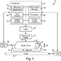
- FIG. 1 is a diagram of an exemplary laser machining system 10 for machining a roll tool, referred to as a work piece.
- the machining can include, for example, making microstructures in the work piece.
- Microstructures can include any type, shape, and dimension of structures on, indenting into, or protruding from the surface of an article.
- microstructure refers to structures having at least one dimension (e.g., height, length, width, or diameter) of less than 2 millimeters (mm) and more preferably less than 1mm.
- Microstructures created using the system described in the present specification can have a 1000 micron pitch, 100 micron pitch, 1 micron pitch, or even a sub-optical wavelength pitch around 200 nanometers (nm). These dimensions are provided for illustrative purposes only, and microstructures made using the system described in the present specification can have any dimension within the range capable of being tooled using the system.
- Computer 12 has, for example, the following components: a memory 14 storing one or more applications 16; a secondary storage 18 providing for non-volatile storage of information; an input device 20 for receiving information or commands; a processor 22 for executing applications stored in memory 16 or secondary storage 18, or received from another source; a display device 24 for outputting a visual display of information; and an output device 26 for outputting information in other forms such as speakers for audio information or a printer for a hardcopy of information.
- a memory 14 storing one or more applications 16
- secondary storage 18 providing for non-volatile storage of information
- an input device 20 for receiving information or commands
- a processor 22 for executing applications stored in memory 16 or secondary storage 18, or received from another source
- a display device 24 for outputting a visual display of information
- an output device 26 for outputting information in other forms such as speakers for audio information or a printer for a hardcopy of information.
- the machining of a work piece 32 is performed by an excimer laser 28 along with an optical system.
- the optical system in this example includes optics and projection mask 30, which selectively blocks portions of a laser beam 31 forming an image for machining a material on work piece 32.
- laser 28 can provide pulses of laser beam 31.
- the laser, optics, and projection mask are generally held stationary while the work piece 32 rotates and translates in a direction substantially perpendicular to laser beam 31.
- a drive unit 36 under control of computer 12, rotates work piece 32 in a direction shown by arrow 33 or a reverse direction.
- mounts 37 and 39 For the translation of work piece 32, it is supported by mounts 37 and 39, which can move work piece laterally along a track 40 in a direction shown by arrow 34 using a drive unit 38 under control of computer 12.
- Mounts 37 and 39, via drive unit 38, can also be configured to move work piece in a direction substantially parallel to laser beam 31 as shown by arrow 35.
- the movement of work piece 32 in the direction shown by arrow 35 can be used to assist in precisely focusing the image formed by laser beam 31 onto the outer surface of work piece 32.
- the laser 28 and work piece 32 can be held stationary, except for rotation of work piece 32 as illustrated by arrow 33, while the optics and mask 30 translate along the work piece.
- system 10 can also be configured for path length compensation of the image generated by laser 28 and optics and mask 30 when they translate along work piece 32.
- FIG. 2 is a diagram illustrating use of optics and a projection mask to form an image on the work piece for machining of it.
- Optics 42 provide laser beam 31 to an imaging mask 44. Based upon a configuration of imaging mask 44, an image of laser beam 31 is provided to imaging optics 46 in order to project the image 48 onto the machinable material 41 of work piece 32.
- System 10 uses imaging, rather than spot writing, for machining of work piece 32.
- spot writing a system works at the focal point of a lens.
- imaging a system works at the image of a projection mask.
- shaped spot writing is an imaging technique using a projection mask and imaging lens to make a simple shape with the laser beam, such as a triangle or crescent, and moving that shape to make a desired shape for machining.
- spot writing the pixel is the beam, usually round and as small as possible.
- shaped spot writing the pixel is a shaped spot, although much larger than the smallest spot possible with the laser beam.
- imaging the pixel is typically the smallest spot possible, but these pixels are all combined into one desired imaging structure for ablation.
- Work piece 32 is typically implemented with a metal roll coated with a laser machinable polymeric material.
- the metal roll can be implemented, for example, with hard copper or with steel coated with nickel or chrome.
- Work piece 32 can be alternatively implemented with aluminum, nickel, steel, or plastics (e.g., acrylics) coated with the machinable polymeric material. Examples of such polymeric materials for machining are described in U.S. Patent Application Serial Nos. 11/278278 (published as US 2007/0235902 A1 ) and 11/278290 (published as US 2007/0231541 A1 ), both of which were filed March 31, 2006.
- the particular material to be used may depend upon, for example, a particular desired application such as various films made using the machined work piece.
- the machinable polymeric material can be implemented with, for example, polyimide and urethane acrylate.
- a diamond-like-glass (DLG) coating can be used to make a durable tool from a laser ablated polyimide roll. DLG is described in U.S. Patent Application Serial No. 11/185078 (published as US 2007/0020451 A1), filed July 20, 2005 .
- a fluoropolymer coating can also be used to improve the durability of an ablated roll.
- Other materials for use as ablation substrates on a work piece include polycarbonate, urethranes, and acrylates.
- the durability of the roll tool (work piece) can also be increased by coating it with a thin layer of nickel, chrome, silver, or other material, which may also enhance its release characteristics.
- the system can also be used to machine other materials such as nanocrystalline metals and fully dense ceramics, particularly metal oxides.
- these materials require about ten times the power for ablation in comparison to the power required to ablate polymers.
- Ceramics can be ablated with the system; however, it can be difficult to make a large roll of, or a roll covered with, a fully dense ceramic material. Smaller rolls of ceramic material can thus be more desirable for ablation.
- the feature size that can be machined is determined by the wavelength of laser light and the numerical aperture of the imaging optics.
- the numerical aperture is the sine of the vertex angle of the largest cone of meridional rays that can enter or leave an optical system or element, multiplied by the refractive index of the medium in which the vertex of the cone is located.
- the machining of work piece 32 is accomplished by coordinated movements of various components.
- the system under control of computer 12, can control movement of work piece in directions 33, 34, and 35 via drive units 36 and 38, while coordinating those movements with control of laser 28 to provide a laser image onto the surface of work piece 32 for machining of it.
- the work piece surface can be stationary during the machining, or preferably it can be in motion with the electronic and laser system delays accounted for by the computer to accurately place the image in its desired location on the surface.
- Work piece 32 after having been machined, can be used to make films having the corresponding microstructures for use in a variety of applications.
- films include optical films, friction control films, and micro-fasteners or other mechanical microstructured components.
- the films are typically made using a coating process in which a material in a viscous state is applied to the work piece, allowed to at least partially solidify, and then removed.
- the film composed of the solidified material will have substantially the opposite structures than those in the work piece. For example, an indentation in the work piece results in a protrusion in the resulting film.
- the laser 28 and optics and projection mask 30 typically remain stationary, while the work piece 32 rotates and translates axially in directions 33 and 34, respectively.
- An axis of small range motion of the roll normal to the beam, direction 35, can be helpful to adjust the focus of the system. Alternatively, this adjustment can be accomplished by moving the optics, the projection mask, or both.
- the work piece is rotated and translated axially while computer 12 controls firing of laser 28 when work piece 32 is in the correct position.
- a 305 mm (12 inch (in)) diameter roll that is 610 mm (24in) long can be completely patterned in only few hours for a shallow pattern.
- the value ⁇ X (56) represents the width of the image on an outer surface 53 of the work piece between points 50 and 51.
- the work piece has a radius R (52), and an angle ⁇ (54) represents half the angular distance of imaged area 56.
- the value ⁇ Z (58) represents the vertical distance of the imaged area 56 perpendicular to an outer surface of the work piece.
- a first approach to imaging on a curved surface involves an optical train that manipulates the excimer laser beam into a long and narrow beam (e.g., 1mm by 20mm) rather than the square beam (5mm by 5mm) conventionally used.
- the projection masks would then be long and narrow, but would not limit the range of patterns that can be created with the system.
- a 1mm wide beam (distance 56) that runs down the axis of the work piece would deviate less than 1 micron (distance 58) from a flat imaging plane for a 152 mm (6in) diameter roll.
- the optical system or projection mask can be configured to provide for an image that deviates less than 20 microns or 10 microns in a distance perpendicular to the outer surface of the work piece. Therefore, when using very large cylinders, the size of the image field in the curved direction can be limited so that the laser image remains in substantial focus for imaging with the focus error equal to 1/2 ⁇ Z (distance 58).
- the final imaging optics can be designed to process the laser beam image in order to produce a cylindrical image plane, in which case system 10 projects a flat image from the projection mask onto a convex cylinder (the work piece).
- This approach curves the image field in one direction, which involves positioning cylindrical lenses in the imaging lens train.
- the amount of processing is typically related to an amount of curvature of the outer surface of the work piece in order to accurately project the flat (processed) image from the projection mask onto the curved surface of the work piece.
- Such an approach can be designed using ray tracing software, for example. Techniques for processing an image for projection onto a curved surface are described in U.S. Patent Nos. 6,715,888 and 6,568,816 .
- This approach of generating a curved image field is preferred for laser ablation machining in that it results in the principal rays of the laser being perpendicular to the outer surface of the cylindrical work piece such that the rays "point" to the center axis of the work piece.
- Another approach according to the invention involves generating a curved image field using a curved mask, such as an etched metal mask, with the amount of curvature of the mask being related to the amount of curvature of the outer surface of the work piece.
- a curved mask such as an etched metal mask
Landscapes
- Physics & Mathematics (AREA)
- Optics & Photonics (AREA)
- Engineering & Computer Science (AREA)
- Plasma & Fusion (AREA)
- Mechanical Engineering (AREA)
- Laser Beam Processing (AREA)
Applications Claiming Priority (2)
| Application Number | Priority Date | Filing Date | Title |
|---|---|---|---|
| US11/941,206 US7985941B2 (en) | 2007-11-16 | 2007-11-16 | Seamless laser ablated roll tooling |
| PCT/US2008/074216 WO2009064527A1 (en) | 2007-11-16 | 2008-08-25 | Seamless laser ablated roll tooling |
Publications (3)
| Publication Number | Publication Date |
|---|---|
| EP2222433A1 EP2222433A1 (en) | 2010-09-01 |
| EP2222433A4 EP2222433A4 (en) | 2016-11-16 |
| EP2222433B1 true EP2222433B1 (en) | 2018-10-10 |
Family
ID=40639057
Family Applications (1)
| Application Number | Title | Priority Date | Filing Date |
|---|---|---|---|
| EP08850223.2A Not-in-force EP2222433B1 (en) | 2007-11-16 | 2008-08-25 | Seamless laser ablated roll tooling |
Country Status (6)
| Country | Link |
|---|---|
| US (2) | US7985941B2 (enExample) |
| EP (1) | EP2222433B1 (enExample) |
| JP (1) | JP5508276B2 (enExample) |
| KR (1) | KR101605921B1 (enExample) |
| CN (1) | CN101861227B (enExample) |
| WO (1) | WO2009064527A1 (enExample) |
Families Citing this family (17)
| Publication number | Priority date | Publication date | Assignee | Title |
|---|---|---|---|---|
| GB0804955D0 (en) * | 2008-03-18 | 2008-04-16 | Rumsby Philip T | Method and apparatus for laser processing the surface of a drum |
| US20110070398A1 (en) * | 2009-09-18 | 2011-03-24 | 3M Innovative Properties Company | Laser ablation tooling via distributed patterned masks |
| US8460754B2 (en) | 2009-12-21 | 2013-06-11 | 3M Innovative Properties Company | Needle coating and in-line curing of a coated workpiece |
| TWI570771B (zh) * | 2011-12-19 | 2017-02-11 | 分子壓模公司 | 使用步進及重複工具之用於壓印微影術之無接縫大區域主模板之製造技術 |
| KR101461883B1 (ko) * | 2012-12-28 | 2014-11-14 | 현대자동차 주식회사 | 크랭크샤프트 열처리장치 |
| DE102014207264A1 (de) * | 2013-04-16 | 2014-10-16 | Audi Hungaria Motor Kft. | Laseraktiviertes Beschichten von Zylinderlaufbahnen |
| DE102013212652B4 (de) * | 2013-06-28 | 2016-12-15 | Continental Automotive Gmbh | Vorrichtung zum Betreiben einer Werkzeugmaschine und Werkzeugmaschine |
| KR102148383B1 (ko) * | 2016-01-22 | 2020-08-26 | 주식회사 포스코 | 방향성 전기강판의 자구미세화 방법과 그 장치 |
| ES2636715B2 (es) * | 2017-06-07 | 2018-02-12 | Sitexco Girona, S.L. | Máquina de limpieza de rodillos anilox por láser y procedimiento para autoajuste del punto focal láser al diámetro del rodillo anilox. |
| US11819940B2 (en) | 2019-02-05 | 2023-11-21 | Dukane Ias, Llc | Systems and methods for laser-welding a workpiece with a laser beam that reaches inaccessible areas of the workpiece using multiple reflecting parts |
| US11931823B2 (en) | 2019-02-05 | 2024-03-19 | Dukane Ias, Llc | Systems and methods for laser-welding a workpiece with a laser beam that reaches inaccessible areas of the workpiece using multiple reflecting parts |
| US10926355B2 (en) * | 2019-02-05 | 2021-02-23 | Dukane Ias, Llc | Systems and methods for laser-welding tubular components using a single, fixed optical reflector with multiple reflecting surfaces |
| CN111679555A (zh) * | 2020-07-08 | 2020-09-18 | 江西沃格光电股份有限公司 | 一种金属辊状模具的制备方法 |
| DE102022001014A1 (de) | 2022-03-22 | 2023-09-28 | SIA Z7 Laboratories | Verfahren zur Bearbeitung von verunreinigten Oberflächen mittels eines Laserstrahls |
| DE102022001013A1 (de) | 2022-03-22 | 2023-09-28 | SIA Z7 Laboratories | Reinigungsvorrichtung für Druckwalzen und Reinigungsverfahren |
| CN114734138A (zh) * | 2022-04-24 | 2022-07-12 | 中国科学院重庆绿色智能技术研究院 | 一种增强空间增材制造丝材激光能量吸收效率的方法 |
| EP4506098A1 (en) | 2023-08-10 | 2025-02-12 | Vilnius University | Method and system for laser processing of elongated thin workpieces using direct laser writing |
Family Cites Families (32)
| Publication number | Priority date | Publication date | Assignee | Title |
|---|---|---|---|---|
| US3701880A (en) * | 1968-11-29 | 1972-10-31 | Westinghouse Electric Corp | Method for sculpturing an indicia or decorative design in the surface of an article with a beam of corpuscular energy |
| US3893795A (en) * | 1970-08-20 | 1975-07-08 | Rowland Dev Corp | Embossing rolls with areas of differential hardness |
| LU80792A1 (fr) * | 1979-01-15 | 1980-08-08 | Ntre De Rech Metallurg Ct Voor | Dispsitif et procede pour effectuer des perforations a la surface des cylindres de laminoirs |
| LU84687A1 (fr) * | 1983-03-11 | 1984-11-14 | Centre Rech Metallurgique | Procede pour ameliorer l'etat de surface d'un cylindre |
| US4758705A (en) * | 1985-08-06 | 1988-07-19 | Eastman Kodak Company | Method and apparatus for texturing a roller |
| DE3881906T2 (de) * | 1987-02-23 | 1994-01-20 | Centre Rech Metallurgique | Verfahren zur Oberflächenmarkierung von Walzwerkswalzen. |
| JPS642798A (en) * | 1987-06-23 | 1989-01-06 | Mitsubishi Electric Corp | Laser beam machine |
| JPH03240980A (ja) * | 1990-02-16 | 1991-10-28 | Kawasaki Steel Corp | 金属ロール表面の加工方法及び装置 |
| JP3350999B2 (ja) * | 1993-03-10 | 2002-11-25 | 富士通株式会社 | ビーム整形レンズモジュール構造 |
| JPH07133704A (ja) * | 1993-11-08 | 1995-05-23 | Nissan Motor Co Ltd | カムシャフトおよびその製造方法 |
| US5538056A (en) * | 1994-12-16 | 1996-07-23 | Beloit Technologies, Inc. | Log conditioning before mechanical debarking |
| WO1996033839A1 (en) | 1995-04-26 | 1996-10-31 | Minnesota Mining And Manufacturing Company | Method and apparatus for step and repeat exposures |
| US5654125A (en) * | 1995-05-01 | 1997-08-05 | E. I. Du Pont De Nemours And Company | Laser apparatus and process of use |
| US5632204A (en) * | 1995-07-27 | 1997-05-27 | Presstek, Inc. | Thin-metal lithographic printing members with integral reflective layers |
| US5733301A (en) * | 1996-01-11 | 1998-03-31 | Schneider (Usa) Inc. | Laser ablation of angioplasty catheters and balloons |
| KR19980061912A (ko) | 1996-12-31 | 1998-10-07 | 서상기 | 무늬 각인용 롤(roll)을 제조하는 방법 및 이를 수행하기 위한 장치 |
| US6222157B1 (en) | 1998-04-17 | 2001-04-24 | L.A. Batchelder And Sons Consulting, Inc. | Seamless holographic transfer using laser generated optical effect patterns |
| US6919162B1 (en) * | 1998-08-28 | 2005-07-19 | Agilent Technologies, Inc. | Method for producing high-structure area texturing of a substrate, substrates prepared thereby and masks for use therein |
| JP2001162384A (ja) * | 1999-12-07 | 2001-06-19 | Ricoh Microelectronics Co Ltd | 光加工方法及びその装置 |
| JP2001208993A (ja) | 2000-01-25 | 2001-08-03 | Sumitomo Heavy Ind Ltd | レーザ描画方法及び描画装置 |
| US6354213B1 (en) * | 2000-04-03 | 2002-03-12 | Jerome D. Jenkins | Method and apparatus for cleaning a metering roll of a printing press |
| US6568816B2 (en) | 2000-10-04 | 2003-05-27 | Panoram Technologies, Inc. | Projection system and method for using a single light source to generate multiple images to be edge blended for arrayed or tiled display |
| US6538230B2 (en) | 2001-05-17 | 2003-03-25 | Preco Laser Systems, Llc | Method and apparatus for improving laser hole resolution |
| JP2003033890A (ja) * | 2001-07-19 | 2003-02-04 | Nippon Steel Corp | レーザ加工方法 |
| CN2526171Y (zh) * | 2002-01-08 | 2002-12-18 | 钱远强 | 一种印刷辊雕刻设备 |
| JP4523757B2 (ja) * | 2003-01-09 | 2010-08-11 | 新日本製鐵株式会社 | レーザ加工装置および加工方法 |
| US6715888B1 (en) | 2003-03-21 | 2004-04-06 | Mitsubishi Electric Research Labs, Inc | Method and system for displaying images on curved surfaces |
| US7190387B2 (en) | 2003-09-11 | 2007-03-13 | Bright View Technologies, Inc. | Systems for fabricating optical microstructures using a cylindrical platform and a rastered radiation beam |
| US7106415B2 (en) * | 2003-12-09 | 2006-09-12 | Anvik Corporation | Illumination compensator for curved surface lithography |
| JP4603838B2 (ja) * | 2004-09-13 | 2010-12-22 | 発紘電機株式会社 | レーザ印字装置、そのプログラム |
| JP4650837B2 (ja) * | 2005-09-22 | 2011-03-16 | 住友電気工業株式会社 | レーザ光学装置 |
| WO2007062130A1 (en) * | 2005-11-22 | 2007-05-31 | J.P. Sercel Associates Inc. | System and method for laser machining of three-dimensional structures |
-
2007
- 2007-11-16 US US11/941,206 patent/US7985941B2/en active Active
-
2008
- 2008-08-25 EP EP08850223.2A patent/EP2222433B1/en not_active Not-in-force
- 2008-08-25 KR KR1020107012872A patent/KR101605921B1/ko not_active Expired - Fee Related
- 2008-08-25 CN CN200880116100.3A patent/CN101861227B/zh not_active Expired - Fee Related
- 2008-08-25 WO PCT/US2008/074216 patent/WO2009064527A1/en not_active Ceased
- 2008-08-25 JP JP2010534069A patent/JP5508276B2/ja active Active
-
2011
- 2011-06-20 US US13/163,811 patent/US8383981B2/en active Active
Non-Patent Citations (1)
| Title |
|---|
| None * |
Also Published As
| Publication number | Publication date |
|---|---|
| KR20100093083A (ko) | 2010-08-24 |
| KR101605921B1 (ko) | 2016-03-23 |
| US7985941B2 (en) | 2011-07-26 |
| WO2009064527A1 (en) | 2009-05-22 |
| CN101861227B (zh) | 2015-03-25 |
| US8383981B2 (en) | 2013-02-26 |
| US20110248004A1 (en) | 2011-10-13 |
| JP2011502795A (ja) | 2011-01-27 |
| EP2222433A1 (en) | 2010-09-01 |
| JP5508276B2 (ja) | 2014-05-28 |
| CN101861227A (zh) | 2010-10-13 |
| US20090127238A1 (en) | 2009-05-21 |
| EP2222433A4 (en) | 2016-11-16 |
Similar Documents
| Publication | Publication Date | Title |
|---|---|---|
| EP2222433B1 (en) | Seamless laser ablated roll tooling | |
| Behrmann et al. | Excimer laser micromachining for rapid fabrication of diffractive optical elements | |
| JP6977609B2 (ja) | 光照射装置、光照射装置を用いた光加工装置、光照射方法、及び光加工方法 | |
| TWI353490B (en) | Projection exposure method and projection exposure | |
| JPH04507479A (ja) | レーザー加工 | |
| JP2009056482A (ja) | 基板分割方法、及び表示装置の製造方法 | |
| CN101846890A (zh) | 并行光刻直写系统 | |
| JP2008006460A5 (enExample) | ||
| Poleshchuk et al. | Laser writing systems and technologies for fabrication of binary and continuous relief diffractive optical elements | |
| JP5130122B2 (ja) | リソグラフィ装置 | |
| US20090316127A1 (en) | Substrate, and method and apparatus for producing the same | |
| CN100495215C (zh) | 对光滑表面进行微米结构光刻蚀的方法及装置 | |
| US20050121428A1 (en) | Laser material processing system | |
| JP2002144069A (ja) | レーザ加工方法 | |
| JP2000061669A (ja) | レーザ加工装置およびその加工方法 | |
| EP1827751B1 (en) | Method for imaging onto a conical surface | |
| JP2006320938A (ja) | レーザ加工方法及び装置 | |
| JP2003287868A (ja) | Opcマスク並びにレーザリペア装置 | |
| KR100692876B1 (ko) | 대상물의 표면에 잔주름 형상 패턴을 형성하기 위한 장치및 방법 | |
| JP5353194B2 (ja) | 立体加工方法および立体加工装置 | |
| Hashimoto et al. | Ultraprecision 5-axis control machining of fly-eye mirror in EUV lithography | |
| JP2001162384A (ja) | 光加工方法及びその装置 | |
| JP2836273B2 (ja) | マスク形レーザー刻印装置 | |
| JPH012798A (ja) | レ−ザ加工装置 | |
| Gao et al. | A Scanning Method based on Parabolic Mirror and Galvanometer for Holographic Contact Copying |
Legal Events
| Date | Code | Title | Description |
|---|---|---|---|
| PUAI | Public reference made under article 153(3) epc to a published international application that has entered the european phase |
Free format text: ORIGINAL CODE: 0009012 |
|
| 17P | Request for examination filed |
Effective date: 20100609 |
|
| AK | Designated contracting states |
Kind code of ref document: A1 Designated state(s): AT BE BG CH CY CZ DE DK EE ES FI FR GB GR HR HU IE IS IT LI LT LU LV MC MT NL NO PL PT RO SE SI SK TR |
|
| AX | Request for extension of the european patent |
Extension state: AL BA MK RS |
|
| DAX | Request for extension of the european patent (deleted) | ||
| RA4 | Supplementary search report drawn up and despatched (corrected) |
Effective date: 20161019 |
|
| RIC1 | Information provided on ipc code assigned before grant |
Ipc: B23K 26/00 20140101AFI20161013BHEP |
|
| STAA | Information on the status of an ep patent application or granted ep patent |
Free format text: STATUS: EXAMINATION IS IN PROGRESS |
|
| 17Q | First examination report despatched |
Effective date: 20171023 |
|
| GRAP | Despatch of communication of intention to grant a patent |
Free format text: ORIGINAL CODE: EPIDOSNIGR1 |
|
| STAA | Information on the status of an ep patent application or granted ep patent |
Free format text: STATUS: GRANT OF PATENT IS INTENDED |
|
| INTG | Intention to grant announced |
Effective date: 20180425 |
|
| GRAS | Grant fee paid |
Free format text: ORIGINAL CODE: EPIDOSNIGR3 |
|
| GRAA | (expected) grant |
Free format text: ORIGINAL CODE: 0009210 |
|
| STAA | Information on the status of an ep patent application or granted ep patent |
Free format text: STATUS: THE PATENT HAS BEEN GRANTED |
|
| AK | Designated contracting states |
Kind code of ref document: B1 Designated state(s): AT BE BG CH CY CZ DE DK EE ES FI FR GB GR HR HU IE IS IT LI LT LU LV MC MT NL NO PL PT RO SE SI SK TR |
|
| REG | Reference to a national code |
Ref country code: GB Ref legal event code: FG4D |
|
| REG | Reference to a national code |
Ref country code: CH Ref legal event code: EP Ref country code: AT Ref legal event code: REF Ref document number: 1050654 Country of ref document: AT Kind code of ref document: T Effective date: 20181015 |
|
| REG | Reference to a national code |
Ref country code: IE Ref legal event code: FG4D |
|
| REG | Reference to a national code |
Ref country code: DE Ref legal event code: R096 Ref document number: 602008057385 Country of ref document: DE |
|
| REG | Reference to a national code |
Ref country code: NL Ref legal event code: MP Effective date: 20181010 |
|
| REG | Reference to a national code |
Ref country code: LT Ref legal event code: MG4D |
|
| REG | Reference to a national code |
Ref country code: AT Ref legal event code: MK05 Ref document number: 1050654 Country of ref document: AT Kind code of ref document: T Effective date: 20181010 |
|
| PG25 | Lapsed in a contracting state [announced via postgrant information from national office to epo] |
Ref country code: NL Free format text: LAPSE BECAUSE OF FAILURE TO SUBMIT A TRANSLATION OF THE DESCRIPTION OR TO PAY THE FEE WITHIN THE PRESCRIBED TIME-LIMIT Effective date: 20181010 |
|
| PG25 | Lapsed in a contracting state [announced via postgrant information from national office to epo] |
Ref country code: ES Free format text: LAPSE BECAUSE OF FAILURE TO SUBMIT A TRANSLATION OF THE DESCRIPTION OR TO PAY THE FEE WITHIN THE PRESCRIBED TIME-LIMIT Effective date: 20181010 Ref country code: LV Free format text: LAPSE BECAUSE OF FAILURE TO SUBMIT A TRANSLATION OF THE DESCRIPTION OR TO PAY THE FEE WITHIN THE PRESCRIBED TIME-LIMIT Effective date: 20181010 Ref country code: PL Free format text: LAPSE BECAUSE OF FAILURE TO SUBMIT A TRANSLATION OF THE DESCRIPTION OR TO PAY THE FEE WITHIN THE PRESCRIBED TIME-LIMIT Effective date: 20181010 Ref country code: HR Free format text: LAPSE BECAUSE OF FAILURE TO SUBMIT A TRANSLATION OF THE DESCRIPTION OR TO PAY THE FEE WITHIN THE PRESCRIBED TIME-LIMIT Effective date: 20181010 Ref country code: BG Free format text: LAPSE BECAUSE OF FAILURE TO SUBMIT A TRANSLATION OF THE DESCRIPTION OR TO PAY THE FEE WITHIN THE PRESCRIBED TIME-LIMIT Effective date: 20190110 Ref country code: IS Free format text: LAPSE BECAUSE OF FAILURE TO SUBMIT A TRANSLATION OF THE DESCRIPTION OR TO PAY THE FEE WITHIN THE PRESCRIBED TIME-LIMIT Effective date: 20190210 Ref country code: LT Free format text: LAPSE BECAUSE OF FAILURE TO SUBMIT A TRANSLATION OF THE DESCRIPTION OR TO PAY THE FEE WITHIN THE PRESCRIBED TIME-LIMIT Effective date: 20181010 Ref country code: FI Free format text: LAPSE BECAUSE OF FAILURE TO SUBMIT A TRANSLATION OF THE DESCRIPTION OR TO PAY THE FEE WITHIN THE PRESCRIBED TIME-LIMIT Effective date: 20181010 Ref country code: AT Free format text: LAPSE BECAUSE OF FAILURE TO SUBMIT A TRANSLATION OF THE DESCRIPTION OR TO PAY THE FEE WITHIN THE PRESCRIBED TIME-LIMIT Effective date: 20181010 Ref country code: NO Free format text: LAPSE BECAUSE OF FAILURE TO SUBMIT A TRANSLATION OF THE DESCRIPTION OR TO PAY THE FEE WITHIN THE PRESCRIBED TIME-LIMIT Effective date: 20190110 |
|
| PG25 | Lapsed in a contracting state [announced via postgrant information from national office to epo] |
Ref country code: SE Free format text: LAPSE BECAUSE OF FAILURE TO SUBMIT A TRANSLATION OF THE DESCRIPTION OR TO PAY THE FEE WITHIN THE PRESCRIBED TIME-LIMIT Effective date: 20181010 Ref country code: PT Free format text: LAPSE BECAUSE OF FAILURE TO SUBMIT A TRANSLATION OF THE DESCRIPTION OR TO PAY THE FEE WITHIN THE PRESCRIBED TIME-LIMIT Effective date: 20190210 Ref country code: GR Free format text: LAPSE BECAUSE OF FAILURE TO SUBMIT A TRANSLATION OF THE DESCRIPTION OR TO PAY THE FEE WITHIN THE PRESCRIBED TIME-LIMIT Effective date: 20190111 |
|
| REG | Reference to a national code |
Ref country code: DE Ref legal event code: R097 Ref document number: 602008057385 Country of ref document: DE |
|
| PG25 | Lapsed in a contracting state [announced via postgrant information from national office to epo] |
Ref country code: CZ Free format text: LAPSE BECAUSE OF FAILURE TO SUBMIT A TRANSLATION OF THE DESCRIPTION OR TO PAY THE FEE WITHIN THE PRESCRIBED TIME-LIMIT Effective date: 20181010 Ref country code: DK Free format text: LAPSE BECAUSE OF FAILURE TO SUBMIT A TRANSLATION OF THE DESCRIPTION OR TO PAY THE FEE WITHIN THE PRESCRIBED TIME-LIMIT Effective date: 20181010 Ref country code: IT Free format text: LAPSE BECAUSE OF FAILURE TO SUBMIT A TRANSLATION OF THE DESCRIPTION OR TO PAY THE FEE WITHIN THE PRESCRIBED TIME-LIMIT Effective date: 20181010 |
|
| PLBE | No opposition filed within time limit |
Free format text: ORIGINAL CODE: 0009261 |
|
| STAA | Information on the status of an ep patent application or granted ep patent |
Free format text: STATUS: NO OPPOSITION FILED WITHIN TIME LIMIT |
|
| PG25 | Lapsed in a contracting state [announced via postgrant information from national office to epo] |
Ref country code: SK Free format text: LAPSE BECAUSE OF FAILURE TO SUBMIT A TRANSLATION OF THE DESCRIPTION OR TO PAY THE FEE WITHIN THE PRESCRIBED TIME-LIMIT Effective date: 20181010 Ref country code: EE Free format text: LAPSE BECAUSE OF FAILURE TO SUBMIT A TRANSLATION OF THE DESCRIPTION OR TO PAY THE FEE WITHIN THE PRESCRIBED TIME-LIMIT Effective date: 20181010 Ref country code: RO Free format text: LAPSE BECAUSE OF FAILURE TO SUBMIT A TRANSLATION OF THE DESCRIPTION OR TO PAY THE FEE WITHIN THE PRESCRIBED TIME-LIMIT Effective date: 20181010 |
|
| 26N | No opposition filed |
Effective date: 20190711 |
|
| PG25 | Lapsed in a contracting state [announced via postgrant information from national office to epo] |
Ref country code: SI Free format text: LAPSE BECAUSE OF FAILURE TO SUBMIT A TRANSLATION OF THE DESCRIPTION OR TO PAY THE FEE WITHIN THE PRESCRIBED TIME-LIMIT Effective date: 20181010 |
|
| PG25 | Lapsed in a contracting state [announced via postgrant information from national office to epo] |
Ref country code: TR Free format text: LAPSE BECAUSE OF FAILURE TO SUBMIT A TRANSLATION OF THE DESCRIPTION OR TO PAY THE FEE WITHIN THE PRESCRIBED TIME-LIMIT Effective date: 20181010 |
|
| GBPC | Gb: european patent ceased through non-payment of renewal fee |
Effective date: 20190825 |
|
| PG25 | Lapsed in a contracting state [announced via postgrant information from national office to epo] |
Ref country code: MC Free format text: LAPSE BECAUSE OF FAILURE TO SUBMIT A TRANSLATION OF THE DESCRIPTION OR TO PAY THE FEE WITHIN THE PRESCRIBED TIME-LIMIT Effective date: 20181010 Ref country code: CH Free format text: LAPSE BECAUSE OF NON-PAYMENT OF DUE FEES Effective date: 20190831 Ref country code: LU Free format text: LAPSE BECAUSE OF NON-PAYMENT OF DUE FEES Effective date: 20190825 Ref country code: LI Free format text: LAPSE BECAUSE OF NON-PAYMENT OF DUE FEES Effective date: 20190831 |
|
| REG | Reference to a national code |
Ref country code: BE Ref legal event code: MM Effective date: 20190831 |
|
| PG25 | Lapsed in a contracting state [announced via postgrant information from national office to epo] |
Ref country code: IE Free format text: LAPSE BECAUSE OF NON-PAYMENT OF DUE FEES Effective date: 20190825 Ref country code: FR Free format text: LAPSE BECAUSE OF NON-PAYMENT OF DUE FEES Effective date: 20190831 |
|
| PG25 | Lapsed in a contracting state [announced via postgrant information from national office to epo] |
Ref country code: BE Free format text: LAPSE BECAUSE OF NON-PAYMENT OF DUE FEES Effective date: 20190831 Ref country code: GB Free format text: LAPSE BECAUSE OF NON-PAYMENT OF DUE FEES Effective date: 20190825 |
|
| PGFP | Annual fee paid to national office [announced via postgrant information from national office to epo] |
Ref country code: DE Payment date: 20200812 Year of fee payment: 13 |
|
| PG25 | Lapsed in a contracting state [announced via postgrant information from national office to epo] |
Ref country code: CY Free format text: LAPSE BECAUSE OF FAILURE TO SUBMIT A TRANSLATION OF THE DESCRIPTION OR TO PAY THE FEE WITHIN THE PRESCRIBED TIME-LIMIT Effective date: 20181010 |
|
| PG25 | Lapsed in a contracting state [announced via postgrant information from national office to epo] |
Ref country code: HU Free format text: LAPSE BECAUSE OF FAILURE TO SUBMIT A TRANSLATION OF THE DESCRIPTION OR TO PAY THE FEE WITHIN THE PRESCRIBED TIME-LIMIT; INVALID AB INITIO Effective date: 20080825 Ref country code: MT Free format text: LAPSE BECAUSE OF FAILURE TO SUBMIT A TRANSLATION OF THE DESCRIPTION OR TO PAY THE FEE WITHIN THE PRESCRIBED TIME-LIMIT Effective date: 20181010 |
|
| REG | Reference to a national code |
Ref country code: DE Ref legal event code: R119 Ref document number: 602008057385 Country of ref document: DE |
|
| PG25 | Lapsed in a contracting state [announced via postgrant information from national office to epo] |
Ref country code: DE Free format text: LAPSE BECAUSE OF NON-PAYMENT OF DUE FEES Effective date: 20220301 |