EP2221171B1 - Verfahren und Vorrichtung zum Herstellen von Schachteln aus Papier oder Pappe - Google Patents
Verfahren und Vorrichtung zum Herstellen von Schachteln aus Papier oder Pappe Download PDFInfo
- Publication number
- EP2221171B1 EP2221171B1 EP09002377A EP09002377A EP2221171B1 EP 2221171 B1 EP2221171 B1 EP 2221171B1 EP 09002377 A EP09002377 A EP 09002377A EP 09002377 A EP09002377 A EP 09002377A EP 2221171 B1 EP2221171 B1 EP 2221171B1
- Authority
- EP
- European Patent Office
- Prior art keywords
- matrix
- strip
- feature
- circumferential surface
- box
- Prior art date
- Legal status (The legal status is an assumption and is not a legal conclusion. Google has not performed a legal analysis and makes no representation as to the accuracy of the status listed.)
- Not-in-force
Links
- 239000011087 paperboard Substances 0.000 title claims description 16
- 239000011111 cardboard Substances 0.000 title claims description 15
- 238000000034 method Methods 0.000 title claims description 13
- 239000011159 matrix material Substances 0.000 claims description 25
- 239000000853 adhesive Substances 0.000 claims description 13
- 230000001070 adhesive effect Effects 0.000 claims description 13
- 238000003825 pressing Methods 0.000 claims description 5
- 239000011324 bead Substances 0.000 claims description 3
- 238000005520 cutting process Methods 0.000 claims description 3
- 238000004026 adhesive bonding Methods 0.000 claims description 2
- 230000004888 barrier function Effects 0.000 claims description 2
- 238000005452 bending Methods 0.000 claims 1
- 230000000717 retained effect Effects 0.000 claims 1
- 238000011144 upstream manufacturing Methods 0.000 claims 1
- 210000002105 tongue Anatomy 0.000 description 8
- 238000004519 manufacturing process Methods 0.000 description 4
- 241000191291 Abies alba Species 0.000 description 2
- 244000299461 Theobroma cacao Species 0.000 description 1
- 235000019219 chocolate Nutrition 0.000 description 1
- 238000005516 engineering process Methods 0.000 description 1
- 239000003292 glue Substances 0.000 description 1
- 230000001788 irregular Effects 0.000 description 1
- 239000000123 paper Substances 0.000 description 1
- 238000002360 preparation method Methods 0.000 description 1
- 239000002689 soil Substances 0.000 description 1
- 238000004804 winding Methods 0.000 description 1
Images

Classifications
-
- B—PERFORMING OPERATIONS; TRANSPORTING
- B65—CONVEYING; PACKING; STORING; HANDLING THIN OR FILAMENTARY MATERIAL
- B65D—CONTAINERS FOR STORAGE OR TRANSPORT OF ARTICLES OR MATERIALS, e.g. BAGS, BARRELS, BOTTLES, BOXES, CANS, CARTONS, CRATES, DRUMS, JARS, TANKS, HOPPERS, FORWARDING CONTAINERS; ACCESSORIES, CLOSURES, OR FITTINGS THEREFOR; PACKAGING ELEMENTS; PACKAGES
- B65D5/00—Rigid or semi-rigid containers of polygonal cross-section, e.g. boxes, cartons or trays, formed by folding or erecting one or more blanks made of paper
- B65D5/02—Rigid or semi-rigid containers of polygonal cross-section, e.g. boxes, cartons or trays, formed by folding or erecting one or more blanks made of paper by folding or erecting a single blank to form a tubular body with or without subsequent folding operations, or the addition of separate elements, to close the ends of the body
- B65D5/029—Rigid or semi-rigid containers of polygonal cross-section, e.g. boxes, cartons or trays, formed by folding or erecting one or more blanks made of paper by folding or erecting a single blank to form a tubular body with or without subsequent folding operations, or the addition of separate elements, to close the ends of the body the tubular body presenting a special shape
-
- B—PERFORMING OPERATIONS; TRANSPORTING
- B65—CONVEYING; PACKING; STORING; HANDLING THIN OR FILAMENTARY MATERIAL
- B65D—CONTAINERS FOR STORAGE OR TRANSPORT OF ARTICLES OR MATERIALS, e.g. BAGS, BARRELS, BOTTLES, BOXES, CANS, CARTONS, CRATES, DRUMS, JARS, TANKS, HOPPERS, FORWARDING CONTAINERS; ACCESSORIES, CLOSURES, OR FITTINGS THEREFOR; PACKAGING ELEMENTS; PACKAGES
- B65D5/00—Rigid or semi-rigid containers of polygonal cross-section, e.g. boxes, cartons or trays, formed by folding or erecting one or more blanks made of paper
- B65D5/02—Rigid or semi-rigid containers of polygonal cross-section, e.g. boxes, cartons or trays, formed by folding or erecting one or more blanks made of paper by folding or erecting a single blank to form a tubular body with or without subsequent folding operations, or the addition of separate elements, to close the ends of the body
- B65D5/0209—Rigid or semi-rigid containers of polygonal cross-section, e.g. boxes, cartons or trays, formed by folding or erecting one or more blanks made of paper by folding or erecting a single blank to form a tubular body with or without subsequent folding operations, or the addition of separate elements, to close the ends of the body the tubular body having a curved or partially curved cross-section
-
- B—PERFORMING OPERATIONS; TRANSPORTING
- B65—CONVEYING; PACKING; STORING; HANDLING THIN OR FILAMENTARY MATERIAL
- B65D—CONTAINERS FOR STORAGE OR TRANSPORT OF ARTICLES OR MATERIALS, e.g. BAGS, BARRELS, BOTTLES, BOXES, CANS, CARTONS, CRATES, DRUMS, JARS, TANKS, HOPPERS, FORWARDING CONTAINERS; ACCESSORIES, CLOSURES, OR FITTINGS THEREFOR; PACKAGING ELEMENTS; PACKAGES
- B65D5/00—Rigid or semi-rigid containers of polygonal cross-section, e.g. boxes, cartons or trays, formed by folding or erecting one or more blanks made of paper
- B65D5/02—Rigid or semi-rigid containers of polygonal cross-section, e.g. boxes, cartons or trays, formed by folding or erecting one or more blanks made of paper by folding or erecting a single blank to form a tubular body with or without subsequent folding operations, or the addition of separate elements, to close the ends of the body
- B65D5/12—Rigid or semi-rigid containers of polygonal cross-section, e.g. boxes, cartons or trays, formed by folding or erecting one or more blanks made of paper by folding or erecting a single blank to form a tubular body with or without subsequent folding operations, or the addition of separate elements, to close the ends of the body with end closures formed separately from tubular body
-
- B—PERFORMING OPERATIONS; TRANSPORTING
- B31—MAKING ARTICLES OF PAPER, CARDBOARD OR MATERIAL WORKED IN A MANNER ANALOGOUS TO PAPER; WORKING PAPER, CARDBOARD OR MATERIAL WORKED IN A MANNER ANALOGOUS TO PAPER
- B31B—MAKING CONTAINERS OF PAPER, CARDBOARD OR MATERIAL WORKED IN A MANNER ANALOGOUS TO PAPER
- B31B2105/00—Rigid or semi-rigid containers made by assembling separate sheets, blanks or webs
- B31B2105/002—Making boxes characterised by the shape of the blanks from which they are formed
- B31B2105/0022—Making boxes from tubular webs or blanks, e.g. with separate bottoms, including tube or bottom forming operations
-
- B—PERFORMING OPERATIONS; TRANSPORTING
- B31—MAKING ARTICLES OF PAPER, CARDBOARD OR MATERIAL WORKED IN A MANNER ANALOGOUS TO PAPER; WORKING PAPER, CARDBOARD OR MATERIAL WORKED IN A MANNER ANALOGOUS TO PAPER
- B31B—MAKING CONTAINERS OF PAPER, CARDBOARD OR MATERIAL WORKED IN A MANNER ANALOGOUS TO PAPER
- B31B2110/00—Shape of rigid or semi-rigid containers
-
- B—PERFORMING OPERATIONS; TRANSPORTING
- B31—MAKING ARTICLES OF PAPER, CARDBOARD OR MATERIAL WORKED IN A MANNER ANALOGOUS TO PAPER; WORKING PAPER, CARDBOARD OR MATERIAL WORKED IN A MANNER ANALOGOUS TO PAPER
- B31B—MAKING CONTAINERS OF PAPER, CARDBOARD OR MATERIAL WORKED IN A MANNER ANALOGOUS TO PAPER
- B31B50/00—Making rigid or semi-rigid containers, e.g. boxes or cartons
- B31B50/26—Folding sheets, blanks or webs
- B31B50/28—Folding sheets, blanks or webs around mandrels, e.g. for forming bottoms
- B31B50/30—Folding sheets, blanks or webs around mandrels, e.g. for forming bottoms the mandrels moving
- B31B50/34—Folding sheets, blanks or webs around mandrels, e.g. for forming bottoms the mandrels moving about their own axes
Definitions
- the invention relates to methods for producing boxes of paper or paperboard according to the preamble of claim 1. It further relates to apparatus for producing such boxes according to the preamble of claim 3.
- the strip forming the side wall is first glued to form a ring. Thereafter, the connecting tongues are folded over inwards. Then, this ring is placed by hand on a mold that corresponds to the desired box shape, and fixed. Subsequently, the floor is glued to this shaped ring. After removing the glued unit, a so-called inner mirror is then glued, which covers the connecting tongues.
- the US 2 240 445 A describes a method in which boxes are made of paper or cardboard by the connecting tabs of the side walls of a box are bent and the strip beginning of the side wall is applied to the lateral surface of a cylindrical die whose cross section corresponds to the cross section of the box by means of a male.
- the matrix is glued and the end of the strip glued together. After applying an adhesive bead around the periphery of the bottom, the bottom and the adhesive are pressed against the connection tabs and finally the finished box is removed from the die.
- the present invention has for its object to provide a method by means of which boxes made of paper or cardboard with an irregular cross-section can be made fully machined.
- An essential advantage of the method according to the invention is the complete renunciation of manual work, because the entire process is fully automatic. It has been found that, when the die is rotated, the strip applies exactly not only to the convex but also to the concave sections of the die, in particular since the application can be assisted by the male part.
- the patrix guarantees the correct zero positioning of the die, the correct positioning of the strip beginning, the application of the strip in the concave sections of the die cross section and finally the proper bonding of the strip beginning and end of the strip.
- the steps of "turning” and “fastening” are repeated as many times as the number of concave portions on the circumference of the box. This means that the method is suitable for boxes whose cross section corresponds to a heart, a star, a Christmas tree, etc.
- the invention also relates to devices for producing such boxes.
- the die may be preceded by a device which bends the connecting tongues of the longitudinal side of the paper or cardboard strip, preferably by 90 °.
- a stop which positions the beginning of the strip exactly to the die.
- This stop can be realized as a light barrier.
- the openings in the lateral surface are divided into groups, each group can be connected via a controlled vacuum connection with the vacuum source according to an embodiment of the invention.
- the height of the lateral surface is matched to the height of the strip. This ensures optimum positioning of the strip forming the box side wall.
- suction openings are also provided in the bottom surface of the die. With the help of these suction openings a possibly vorzu Imageder inner mirror can be brought into position before the side wall forming strip is wound up.
- At least one pressure sensor can be switched on between the vacuum source and the die.
- the die is releasably secured to a rotation axis, wherein the rotation axis is at the same time vacuum rotary feedthrough.
- the rotational movement disturbing vacuum hoses can be dispensed with and the die can be rotated endlessly.
- the male is a lifting ram with a cutting edge, which is adapted to the concave portion of the die. This means that the cutting edge is formed so that the strip is optionally kinked when inserted into the concave sections, but of course not separated.
- die and / or male are advantageously interchangeable to produce different box shapes and sizes without long changeover times can.
- a contact edge can be provided on the lateral surface.
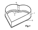
- Fig. 1 shows purely schematically the lower part of a paper or cardboard box in heart shape.
- box shapes are often used for chocolates. Boxes can also have the shape of a Christmas tree, a Santa Claus, an Easter bunny, an Easter egg, an apple or even a star. Common to all of these box shapes is that they can not be made with the box nesting devices known and proven for cubic boxes.
- the pictured box base consists of a bottom 2 made of paper or cardboard, on which a side wall consisting of an elongated strip 1 made of paper or cardboard, which is glued by means of an overlap on the strip beginning 4 into a ring and then adhered to the bottom 2 ,
- a side wall consisting of an elongated strip 1 made of paper or cardboard, which is glued by means of an overlap on the strip beginning 4 into a ring and then adhered to the bottom 2 .
- connecting tongues 3 it is also possible to glue the strip 1 dull on the floor 2. If the connecting tongues 3 are not to be visible, a so-called inner mirror (not shown) is glued.
- Fig. 2 purely schematically illustrated apparatus for producing the in Fig. 1 illustrated box has as essential components a die 10 and a male part 20th
- the die 10 forms the heart of the device. It can be seen a cylinder whose base corresponds to the produced box 1, 2, thus also heart-shaped. In the lateral surface 11 of the die 10 openings 12 are provided in some areas. These are connected via vacuum connections with a vacuum source (not shown). In this way it is possible to form the strip 1 by means of a vacuum on the lateral surface 11 of the die 10 to the side wall and to fix until the bottom 2 is glued. A contact edge 15 ensures the exact position of the strip 1 on the die 11th
- pressure sensors can be inserted into the vacuum feed lines.
- the die 10 is rotated by means of its connection axis 14, to which it is replaceably mounted.
- the strip 1 is wound onto the lateral surface 11. If necessary, the winding is supported by the controlled driving back and forth patrix 20.
- the strip end is pressed by means of the male 20 against the strip beginning 4 until a previously applied adhesive has cured.
- a box bottom (not shown) can be withdrawn from a magazine in a manner known per se with the aid of a vacuum arm and provided with an adhesive bead on the circumference with the aid of an adhesive nozzle.
- This soil will now be using of the vacuum arm on the die 10, the connecting tabs 3 and the side wall forming strip 1 is pressed until the adhesive has cured.
- the finished box with the help of the same or another vacuum arm is withdrawn from the die 10, wherein the peeling process can be assisted by the fact that air is blown out of the vacuum nozzles 12, 13.
- the provided in the bottom of the die 10 vacuum nozzles 13 have the task to hold a possible inner mirror, which is placed on the die 10 before the strip 1 is wound onto the lateral surface.
- the supply of the vacuum to the vacuum nozzles 12, 13 is carried out by a built-in rotary axis 14 vacuum rotary feedthrough.
Landscapes
- Engineering & Computer Science (AREA)
- Mechanical Engineering (AREA)
- Making Paper Articles (AREA)
Description
- Die Erfindung betrifft Verfahren zum Herstellen von Schachteln aus Papier oder Pappe gemäß dem Oberbegriff des Anspruchs 1. Sie betrifft ferner Vorrichtungen zum Herstellen derartiger Schachteln gemäß dem Oberbegriff des Anspruchs 3.
- Die Herstellung von Schachteln aus Papier oder Pappe mit kubischer Form mit Hilfe von vollautomatisch arbeitenden Schachtelaufrichtemaschinen ist bereits sehr gut gelöst. Problematisch ist jedoch nach wie vor die Herstellung von Schachteln mit nicht-kubischer Form, insbesondere wenn der Querschnitt der Schachteln wenigstens einen konkaven Abschnitt und wenigstens einen konvexen Abschnitt aufweist. Derartige Schachteln sind beispielsweise beschrieben in der
DE 20 2006 014 009 U1 , in derDE 10 2006 028 824 A1 und derDE 10 2005 054 982 A1 . Die Herstellung dieser Schachteln erfolgt so, dass ein die Seitenwand bildender langgestreckter Papier- oder Pappestreifen auf den aus Papier oder Pappe bestehenden Boden geklebt wird. Dazu weist der Papier- oder Pappestreifen eine Länge auf, die der Länge des Umfangs des Bodens entspricht. An der Längsseite des die Seitenwand bildenden Streifens sind Verbindungszungen angeformt, die durch eine Knicklinie mit dem Streifen verbunden sind. - Zur Herstellung dieser Schachteln wird der die Seitenwand bildende Streifen zunächst zu einem Ring geklebt. Danach werden die Verbindungszungen nach innen umgeknickt. Sodann wird dieser Ring von Hand auf eine Form, die der gewünschten Schachtelform entspricht, gelegt und fixiert. Anschließend wird auf diesen in Form gebrachten Ring der Boden aufgeklebt. Nach dem Abnehmen der verklebten Einheit wird dann ein sogenannter Innenspiegel eingeklebt, der die Verbindungszungen verdeckt.
- Da die beschriebene Herstellungsweise im Wesentlichen Handarbeit ist, ist sie wenig effizient. Das ist unbefriedigend.
- Die
US 2 240 445 A beschreibt ein Verfahren, bei dem Schachteln aus Papier oder Pappe hergestellt werden, indem die Verbindungszungen der Seitenwände einer Schachtel umgebogen werden und der Streifenanfang der Seitenwand an die Mantelfläche einer zylindrischen Matrize, deren Querschnitt dem Querschnitt der Schachtel entspricht, mit Hilfe einer Patrize angelegt wird. Die Matrize wird geklebt und die Streifenende miteinander verklebt. Nach dem Anbringen einer Klebstoffraupe am Umfang des Bodens werden der Boden und der Klebstoff an die Verbindungszungen angepresst und die fertige Schachtel schließlich von der Matrize abgezogen. - Der vorliegenden Erfindung liegt die Aufgabe zugrunde, ein Verfahren anzugeben, mit dessen Hilfe Schachteln aus Papier oder Pappe mit unregelmäßigem Querschnitt vollmaschinell hergestellt werden können.
- Diese Aufgabe wird gelöst durch ein Verfahren mit den Merkmalen des Anspruchs 1.
- Wesentlicher Vorteil des erfindungsgemäßen Verfahrens ist der völlige Verzicht auf Handarbeit, weil der gesamte Vorgang vollautomatisch abläuft. Es hat sich gezeigt, dass sich der Streifen beim Drehen der Matrize exakt nicht nur an die konvexen sondern auch an die konkaven Abschnitte der Matrize anlegt, insbesondere da das Anlegen durch die Patrize unterstützt werden kann. Dabei garantiert die Patrize die korrekte Null-Positionierung der Matrize, die korrekte Positionierung des Streifenanfangs, das Anlegen des Streifens in den konkaven Abschnitten des Matrizenquerschnitts und schließlich die ordnungsgemäße Verklebung von Streifenanfang und Streifenende.
- Gemäß einer Ausgestaltung der Erfindung werden bei Schachteln mit mehr als einem konkaven und konvexem Abschnitt die Schritte "Drehen" und "Befestigen" so oft wiederholt, wie es der Anzahl konkaver Abschnitte am Umfang der Schachtel entspricht. Das bedeutet, dass das Verfahren geeignet ist für Schachteln, deren Querschnitt einem Herz, einem Stern, einem Tannenbaum usw. entspricht.
- Gegenstand der Erfindung sind auch Vorrichtungen zum Herstellen derartiger Schachteln.
- Diese Aufgabe wird gelöst durch eine Vorrichtung mit den Merkmalen des Anspruchs 3.
- Dank der kombinierten Wirkung von Patrize und Matrize wird der die Seitenwand bildende Papier- oder Pappestreifen von den Vakuumdüsen an der Mantelfläche der Matrize angesaugt, festgehalten und in Form gebracht, bis der Schachtelboden bzw. -deckel angeklebt ist. Dieser Vorgang erfolgt programmgesteuert in kürzester Zeit, ohne dass eine Bedienungsperson Hand anlegen müsste.
- Es versteht sich, dass die exakte Zufuhr des Streifens zur Matrize von besonderer Wichtigkeit ist. Aus diesem Grunde befindet sich gemäß einer Weiterbildung der Erfindung vor der Matrize eine Einrichtung zum exakten Zuführen des Streifens zur Matrize.
- Des Weiteren kann der Matrize eine Einrichtung vorgeschaltet sein, die die Verbindungszungen der Längsseite des Papier- oder Pappestreifens umbiegt, vorzugsweise um 90°.
- Gemäß einer bevorzugten Ausgestaltung der Erfindung ist auch ein Anschlag vorgesehen, der den Anfang des Streifens exakt zur Matrize positioniert. Dieser Anschlag kann als Lichtschranke realisiert sein.
- Um die erforderliche Vakuumleistung gering halten zu können, sind gemäß einer Weiterbildung der Erfindung die Öffnungen in der Mantelfläche in Gruppen aufgeteilt, wobei jede Gruppe über einen gesteuerten Vakuumanschluss mit der Vakuumquelle verbindbar ist.
- Vorteilhafterweise ist die Höhe der Mantelfläche auf die Höhe des Streifens abgestimmt. Dies sorgt für eine optimale Positionierung des die Schachtelseitenwand bildenden Streifens.
- Gemäß einer Weiterbildung der Erfindung sind in der Bodenfläche der Matrize ebenfalls Saugöffnungen vorgesehen. Mit Hilfe dieser Saugöffnungen kann ein eventuell vorzusehender Innenspiegel in Position gebracht werden, bevor der die Seitenwand bildende Streifen aufgewickelt wird.
- Um eine ausreichende Vakuumleistung sicherzustellen, kann zwischen Vakuumquelle und Matrize wenigstens ein Drucksensor eingeschaltet sein.
- Gemäß einer bevorzugten Ausbildung der Erfindung ist die Matrize an einer Drehachse lösbar befestigt, wobei die Drehachse gleichzeitig Vakuumdrehdurchführung ist. Auf diese Weise sind die Drehbewegung störende Vakuumschläuche entbehrlich und die Matrize kann endlos gedreht werden.
- Gemäß einer Ausgestaltung der Erfindung ist die Patrize ein Hubstößel mit einer Schneide, die an die konkaven Abschnitt der Matrize angepasst ist. Das heißt, dass die Schneide so ausgebildet ist, dass der Streifen beim Einlegen in die konkaven Abschnitte gegebenenfalls geknickt aber natürlich nicht abgetrennt wird.
- Es versteht sich, dass Matrize und/oder Patrize vorteilhafterweise auswechselbar sind, um ohne lange Umrüstzeiten unterschiedliche Schachtelformen und -größen produzieren zu können.
- Gemäß einer Weiterbildung der Erfindung befindet sich vor der Matrize eine Einrichtung zum Anpressen des beleimten Schachtelbodens oder -deckels an die aus dem Streifen gebildete Seitenwand, die Verbindungszungen und/oder einen etwaigen Innenspiegel.
- Vorteilhafterweise sind zum Auftragen von Klebstoff, sei es auf Streifenanfang bzw. -ende oder Schachtelboden- bzw. -deckel, Klebstoffdüsen vorgesehen.
- Um die Positionierung des Streifens auf der Matrize zu verbessern, kann an der Mantelfläche eine Anlegekante vorgesehen sein.
- Anhand der Zeichnung soll die Erfindung in Form eines rein schematisch dargestellten Ausführungsbeispiels näher erläutert werden. Es zeigen in isometrischer Darstellung
- Fig. 1
- ein Schachtelunterteil in Herzform und
- Fig. 2
- die zum Verständnis der Erfindung wesentlichen Elemente einer Vorrichtung zum Herstellen der herzförmigen Papier- oder Pappeschachteln gemäß
Fig. 1 . -
Fig. 1 zeigt rein schematisch das Unterteil einer Papier- oder Pappeschachtel in Herzform. Derartige Schachtelformen werden häufig für Pralinen verwendet. Schachteln können auch die Form eines Tannenbaums, eines Nikolaus, eines Osterhasen, eines Ostereis, eines Apfels oder auch eines Sterns haben. Gemeinsam ist allen diesen Schachtelformen, dass sie nicht mit den für kubische Schachteln bekannten und bewährten Schachtelaufrichtevorrichtungen hergestellt werden können. - Wie
Fig. 1 zeigt, besteht das abgebildete Schachtelunterteil aus einem Boden 2 aus Papier oder Pappe, auf dem eine Seitenwand, bestehend aus einem langgestreckten Streifen 1 aus Papier oder Pappe, der mittels einer Überlappung am Streifenanfang 4 zu einem Ring geklebt und anschließend auf den Boden 2 aufgeklebt ist. Zum Aufkleben sind Verbindungszungen 3 vorgesehen. Es ist jedoch auch möglich, den Streifen 1 stumpf auf den Boden 2 zu kleben. Falls die Verbindungszungen 3 nicht sichtbar sein sollen, wird ein sogenannter Innenspiegel (nicht dargestellt) eingeklebt. - Die Herstellung eines passenden Schachteldeckels erfolgt grundsätzlich auf dieselbe Art und Weise, lediglich die Abmessungen müssen angepasst werden.
- Die in
Fig. 2 rein schematisch dargestellte Vorrichtung zur Herstellung der inFig. 1 dargestellten Schachtel besitzt als wesentliche Bestandteile eine Matrize 10 und eine Patrize 20. - Die Matrize 10 bildet das Herzstück der Vorrichtung. Man erkennt einen Zylinder, dessen Grundfläche der herzustellenden Schachtel 1, 2 entspricht, somit ebenfalls herzförmig ist. In der Mantelfläche 11 der Matrize 10 sind bereichsweise Öffnungen 12 vorgesehen. Diese sind über Vakuumanschlüsse mit einer Vakuumquelle (nicht dargestellt) verbindbar. Auf diese Weise ist es möglich, den Streifen 1 mittels Vakuum an der Mantelfläche 11 der Matrize 10 zur Seitenwand zu formen und zu fixieren, bis der Boden 2 aufgeklebt ist. Eine Anlegekante 15 gewährleistet die exakte Lage des Streifens 1 auf der Matrize 11.
- Um erkennen zu können, ob der Streifen 1 korrekt an der Mantelfläche 11 anliegt und die Öffnungen 12 verschließt, können in die Vakuumzuleitungen Drucksensoren eingefügt werden.
- Wie man in
Fig. 2 sehen kann, wird der Streifen 1 mit bereits um etwa 90° umgelegten Verbindungszungen 3 vorgeschoben, bis der Streifenanfang 4 gegen einen Anschlag 30 stößt. Darauf fährt die Patrize 20 nach unten und positioniert den Streifenanfang 4 genau in dem konkaven Einschnitt der herzförmigen Matrize 10. Dort wird der Streifenanfang 4 von einer Vakuumdüse festgehalten. - Anschließend wird die Matrize 10 mit Hilfe ihrer Verbindungsachse 14, an der sie auswechselbar befestigt ist, gedreht. Dabei wird der Streifen 1 auf die Mantelfläche 11 aufgewickelt. Falls nötig wird das Aufwickeln durch die gesteuert vor und zurück fahrende Patrize 20 unterstützt.
- Sobald der Streifen 1 ganz auf die Matrize 10 aufgewickelt ist, wird das Streifenende mit Hilfe der Patrize 20 gegen den Streifenanfang 4 gepresst, bis ein zuvor angebrachter Klebstoff ausgehärtet ist.
- Anschließend kann ein Schachtelboden (nicht dargestellt) in an sich bekannter Weise mit Hilfe eines Vakuumarms aus einem Magazin abgezogen und am Umfang mit Hilfe einer Klebstoffdüse mit einer Klebstoffraupe versehen werden. Dieser Boden wird nun mit Hilfe des Vakuumarms auf die Matrize 10, die Verbindungszungen 3 und den die Seitenwand bildenden Streifen 1 aufgepresst, bis der Klebstoff ausgehärtet ist. Anschließend wird die fertige Schachtel mit Hilfe desselben oder eines anderen Vakuumarms von der Matrize 10 abgezogen, wobei der Abziehvorgang dadurch unterstützt werden kann, dass aus den Vakuumdüsen 12, 13 Luft geblasen wird.
- Die im Boden der Matrize 10 vorgesehenen Vakuumdüsen 13 haben die Aufgabe, einen etwaigen Innenspiegel festzuhalten, der auf die Matrize 10 aufgelegt wird, bevor der Streifen 1 auf die Mantelfläche aufgewickelt wird.
- Die Zufuhr des Vakuums zu den Vakuumdüsen 12, 13 erfolgt durch eine in die Drehachse 14 integrierte Vakuumdrehdurchführung.
- Nicht dargestellt sind in den Figuren die Magazine, die die Zuschnitte für Seitenwand, Boden und Innenspiegel vorrätig halten. Ebenso wenig sind dargestellt die Vorrichtungen, die die Zuschnitte aus den Magazinen abziehen und sie den Bearbeitungsstellen zuführen. Ebenso wenig dargestellt ist die Vakuumquelle. Diese Funktionselemente sind in herkömmlicher Technik realisiert. Bei ihrer Darstellung in der Zeichnung würde diese unübersichtlich und damit unverständlich werden.
Claims (16)
- Verfahren zum Herstellen von Schachteln aus Papier oder Pappe, wobei die Schachteln einen Boden (2) oder einen Deckel mit einer aufgeklebten Seitenwand aufweisen und die Seitenwände aus einem Streifen (1) mit einem Anfang (4), einem Ende und Verbindungszungen (3) an einer Längsseite gebildet sind, umfassend die Schritte:- Umbiegen der Verbindungszungen (3) um etwa 90 Grad,- Anlegen des Streifenanfangs (4) an die Mantelfläche (11) einer zylindrischen Matrize (10), deren Querschnitt dem Querschnitt der Schachtel entspricht, mit Hilfe einer Patrize (20),- Drehen der Matrize (10), wobei der Streifen (1) an einem konvexen Abschnitt der Matrize (10) angesaugt und festgehalten wird,- Anbringen von Klebestoff am Anfang (4) oder Ende des Streifens (1)- Verkleben von Streifenanfang (4) und Streifenende,- Anbringen einer Klebestoffraupe am Umfang des Bodens (2),- Anpressen von Boden (2) und Klebestoff an die Verbindungszungen (3)- Abziehen der fertigen Schachtel von der Matrize (10), dadurch gekennzeichnet, dass die Befestigung des Streifens (1) an einem Abschnitt der Mantelfläche (11) mittels Vakuum erfolgt, wobei die Verbindungszungen (3) gegen die Bodenfläche der Matrize (10) gelegt werden.
- Verfahren nach Anspruch 1 zum Herstellen von Schachteln, deren Querschnitt mehr als einen konkaven Abschnitt und mehr als einen konvexen Abschnitt aufweist, gekennzeichnet durch das Merkmal:- Andrücken des Streifens (1) an einem konkaven Abschnitt der Mantelfläche (11) mit Hilfe der Patrize (20),- Drehen der Matrize (10) bis zum nächsten konkaven Abschnitt der Mantelfläche (11),- Wiederholen der Schritte "Andrücken" und "Drehen" entsprechend der Anzahl konkaver Abschnitte am Umfang der Schachtel.
- Vorrichtung zum Herstellen von Schachteln aus Papier oder Pappe, wobei die Schachteln einen Boden (2) und/oder einen Deckel mit einer aufgeklebten Seitenwand aufweisen, die Seitenwände aus einem Streifen (1) mit einem Anfang (4), einem Ende und Verbindungszungen (3) an einer Längsseite gebildet sind und der Querschnitt der Schachteln wenigstens einen konkaven Abschnitt und wenigstens einen konvexen Abschnitt aufweist,
umfassend:- eine zylindrische Matrize (10), deren Grundfläche der Form der herzustellenden Schachtel entspricht,- und eine Patrize (20), die in wenigstens einer Achse beweglich ist,- die Matrize (10) ist drehbar gelagert,- die Patrize (20) besitzt eine Wirkfläche (21), die mit der Mantelfläche (11) der Matrize (10) kooperiert und auf diese Weise den Streifen (1) an die Matrize (10) annähert bzw. anlegt, dadurch gekennzeichnet, dass in der Mantelfläche (11) der Matrize (10) Öffnungen (12) vorgesehen sind, die mit einer Vakuumquelle verbindbar sind und auf diese Weise den Streifen (1) an der Matrize (10) festhalten. - Vorrichtung nach Anspruch 3, gekennzeichnet durch das Merkmal:- vor der Matrize (10) befindet sich eine Einrichtung zum exakten Zuführen des Streifens (1) zur Matrize (10).
- Vorrichtung nach Anspruch 3 oder 4, gekennzeichnet durch das Merkmal:- der Matrize (10) ist eine Einrichtung vorgeschaltet, die die Verbindungszungen (3) umbiegt.
- Vorrichtung nach Anspruch 3, 4 oder 5, gekennzeichnet durch das Merkmal:- ein Anschlag (30), beispielsweise in Form einer Lichtschranke, positioniert den Anfang des Streifens (1) exakt zur Matrize (10).
- Vorrichtung nach Anspruch 3, gekennzeichnet durch die Merkmale:- die Öffnungen (12) in der Mantelfläche (11) der Matrize (10) sind in Gruppen aufgeteilt,- jede Gruppe ist über einen gesteuerten Vakuumanschluss mit der Vakuumquelle verbindbar.
- Vorrichtung nach einem der Ansprüche 3 bis 7, gekennzeichnet durch das Merkmal:- die Höhe der Mantelfläche (11) ist auf die Höhe des Streifens (1) abgestimmt.
- Vorrichtung nach einem der Ansprüche 3 bis 8, gekennzeichnet durch das Merkmai:- in der Bodenfläche der Matrize (10) sind Saugöffnungen (13) vorgesehen.
- Vorrichtung nach einem der Ansprüche 3 bis 9, gekennzeichnet durch das Merkmal:- zwischen Vakuumquelle und Matrize (10) ist wenigstens ein Drucksensor eingeschaltet.
- Vorrichtung nach einem der Ansprüche 3 bis 10, gekennzeichnet durch die Merkmale:- die Matrize (10) ist an einer Drehachse (14) lösbar befestigt,- die Drehachse (14) ist gleichzeitig Vakuumdrehdurchführung.
- Vorrichtung nach einem der Ansprüche 3 bis 8, gekennzeichnet durch das Merkmal:- die Patrize (20) ist ein Hubstößel mit einer Schneide (21), die an die konkaven Abschnitte der Matrize (10) angepasst ist.
- Vorrichtung nach einem der Ansprüche 3 bis 12, gekennzeichnet durch das Merkmal:- Matrize (10) und Patrize (20) sind auswechselbar.
- Vorrichtung nach einem der Ansprüche 3 bis 13, gekennzeichnet durch das Merkmal:- vor der Matrize (10) befindet sich wenigstens eine Einrichtung zum Anpressen des beleimten Schachtelbodens (2) und/oder -deckels an die aus dem Streifen (1) gebildete Seitenwand, die Verbindungszungen (3) und/oder einen Innenspiegel.
- Vorrichtung nach einem der Ansprüche 3 bis 14, gekennzeichnet durch das Merkmal:- zum Auftragen von Klebstoff sind Klebstoffdüsen vorgesehen.
- Vorrichtung nach einem der Ansprüche 3 bis 15, gekennzeichnet durch das Merkmal:- an der Mantelfläche (11) der Matrize (20) ist eine Anlegekante (15) für den Streifen (1) vorgesehen.
Priority Applications (5)
| Application Number | Priority Date | Filing Date | Title |
|---|---|---|---|
| EP09002377A EP2221171B1 (de) | 2009-02-20 | 2009-02-20 | Verfahren und Vorrichtung zum Herstellen von Schachteln aus Papier oder Pappe |
| JP2010028798A JP2010195041A (ja) | 2009-02-20 | 2010-02-12 | 紙または厚紙から成る箱の製造方法と製造装置 |
| CA2693758A CA2693758A1 (en) | 2009-02-20 | 2010-02-19 | Method and apparatus for manufacturing boxes made of paper or cardboard |
| EA201000241A EA018051B1 (ru) | 2009-02-20 | 2010-02-19 | Способ и устройство для изготовления коробок из бумаги или картона |
| US12/710,144 US8382648B2 (en) | 2009-02-20 | 2010-02-22 | Method and apparatus for manufacturing boxes made of paper or cardboard |
Applications Claiming Priority (1)
| Application Number | Priority Date | Filing Date | Title |
|---|---|---|---|
| EP09002377A EP2221171B1 (de) | 2009-02-20 | 2009-02-20 | Verfahren und Vorrichtung zum Herstellen von Schachteln aus Papier oder Pappe |
Publications (2)
| Publication Number | Publication Date |
|---|---|
| EP2221171A1 EP2221171A1 (de) | 2010-08-25 |
| EP2221171B1 true EP2221171B1 (de) | 2012-06-27 |
Family
ID=40863726
Family Applications (1)
| Application Number | Title | Priority Date | Filing Date |
|---|---|---|---|
| EP09002377A Not-in-force EP2221171B1 (de) | 2009-02-20 | 2009-02-20 | Verfahren und Vorrichtung zum Herstellen von Schachteln aus Papier oder Pappe |
Country Status (5)
| Country | Link |
|---|---|
| US (1) | US8382648B2 (de) |
| EP (1) | EP2221171B1 (de) |
| JP (1) | JP2010195041A (de) |
| CA (1) | CA2693758A1 (de) |
| EA (1) | EA018051B1 (de) |
Families Citing this family (8)
| Publication number | Priority date | Publication date | Assignee | Title |
|---|---|---|---|---|
| EP2521647B1 (de) * | 2010-01-07 | 2017-10-25 | Mohrbach Verpackungsmaschinen GmbH | Verfahren und vorrichtung zum herstellen von schachteldeckeln und/oder schachtelböden aus papier oder pappe |
| EP2521646A1 (de) * | 2010-01-07 | 2012-11-14 | Mohrbach Verpackungsmaschinen GmbH | Verfahren und vorrichtung zum herstellen von schachteln aus papier oder pappe |
| CN102825835B (zh) * | 2011-06-17 | 2014-09-03 | 山东新华包装有限公司 | 一种全纸包装桶的去角折边设备及其生产工艺 |
| CN102837451A (zh) * | 2012-09-04 | 2012-12-26 | 苏州工业园区维特力彩印包装有限公司 | 用于基纸的上胶装置 |
| CN105599356A (zh) * | 2015-12-21 | 2016-05-25 | 广州美普森包装有限公司 | 一种包装盒流水生产线及生产方法 |
| CN107572090B (zh) * | 2017-09-02 | 2019-07-16 | 上海美美尚隽印刷有限公司 | 一种异型盒以及该异型盒的制作工艺 |
| CN113998259B (zh) * | 2020-05-27 | 2024-02-06 | 深圳市望盛科技有限公司 | 一种特种盒身结构 |
| CN115635737B (zh) * | 2022-10-10 | 2024-10-15 | 安徽美阅文化发展股份有限公司 | 一种礼盒自动生产线 |
Family Cites Families (20)
| Publication number | Priority date | Publication date | Assignee | Title |
|---|---|---|---|---|
| US1568608A (en) * | 1925-03-09 | 1926-01-05 | Klein Adolph | Box construction |
| US1664739A (en) * | 1927-02-24 | 1928-04-03 | Irving A Deline | Box holder to facilitate the hand-stripping operation in the production of pasteboard boxes |
| US1987627A (en) * | 1932-07-29 | 1935-01-15 | Jr Gideon R Kreider | Method and apparatus for wrapping boxes |
| GB420002A (en) * | 1932-07-29 | 1934-11-19 | Gideon Richie Kreider Junior | Method and apparatus for making boxes |
| GB419741A (en) * | 1932-07-29 | 1934-11-19 | Gideon Richie Kreider Junior | Method and apparatus for making boxes |
| US2115745A (en) * | 1933-10-30 | 1938-05-03 | President And Directors Of The | Container |
| US2119360A (en) * | 1936-05-18 | 1938-05-31 | Frank J Schleicher | Box or carton |
| US2240445A (en) | 1939-04-10 | 1941-04-29 | Paper Package Company | Box forming machine |
| US2950849A (en) * | 1959-09-16 | 1960-08-30 | Douglas B Ortleb | Box construction |
| US3016178A (en) * | 1960-02-19 | 1962-01-09 | Charles J Knocks | Box construction |
| US3250186A (en) * | 1962-07-27 | 1966-05-10 | Reynolds Metals Co | Method and apparatus for making frusto-conical label constructions for bottles and the like |
| US3643554A (en) * | 1970-03-20 | 1972-02-22 | Thermo Dielectric Machine Co I | Box manufacturing apparatus |
| DE2650097A1 (de) * | 1976-10-30 | 1978-05-03 | Rissen Gmbh Maschf | Vorrichtung fuer die schliessung von laengsnaehten von konischen gefaessen |
| US4395253A (en) * | 1978-12-28 | 1983-07-26 | Consolidated Foods Corporation | Method of making corrugated packages |
| US4581003A (en) * | 1983-07-08 | 1986-04-08 | Toppan Printing Co., Ltd. | Method for manufacturing an angled and cylindrical container |
| JPH03124544A (ja) * | 1989-10-06 | 1991-05-28 | Nippon Uiringu Kk | 変形紙筒胴を有する容器及びその製造方法 |
| US5400917A (en) * | 1992-07-31 | 1995-03-28 | Stanton; Steven W. | Box Construction and method |
| DE102005054982A1 (de) | 2005-11-16 | 2007-07-12 | Silcoplan Engineering Gmbh | Doppelwandige Verpackungsschachtel und Verfahren zum Herstellen einer solchen |
| DE102006028824A1 (de) | 2006-05-02 | 2007-11-08 | Leunisman Gmbh | Faltschachtel mit doppelwandigem Rumpf |
| DE202006014009U1 (de) | 2006-09-08 | 2007-08-16 | Finega S.A. | Schachtel bestehend aus einer an einen Boden angesetzten Seitenwand |
-
2009
- 2009-02-20 EP EP09002377A patent/EP2221171B1/de not_active Not-in-force
-
2010
- 2010-02-12 JP JP2010028798A patent/JP2010195041A/ja active Pending
- 2010-02-19 CA CA2693758A patent/CA2693758A1/en not_active Abandoned
- 2010-02-19 EA EA201000241A patent/EA018051B1/ru not_active IP Right Cessation
- 2010-02-22 US US12/710,144 patent/US8382648B2/en not_active Expired - Fee Related
Also Published As
| Publication number | Publication date |
|---|---|
| CA2693758A1 (en) | 2010-08-20 |
| EP2221171A1 (de) | 2010-08-25 |
| EA201000241A1 (ru) | 2010-08-30 |
| EA018051B1 (ru) | 2013-05-30 |
| US8382648B2 (en) | 2013-02-26 |
| US20100216617A1 (en) | 2010-08-26 |
| JP2010195041A (ja) | 2010-09-09 |
Similar Documents
| Publication | Publication Date | Title |
|---|---|---|
| EP2221171B1 (de) | Verfahren und Vorrichtung zum Herstellen von Schachteln aus Papier oder Pappe | |
| EP3147115B1 (de) | Maschine und verfahren zur herstellung eines bechers | |
| DE68907622T2 (de) | Verfahren und Maschine für die Herstellung von polygonalen Schachteln aus Bogenmaterial und daraus hergestellte Schachtel. | |
| EP1990184A1 (de) | Vorrichtung zum Herstellen einer konischen Hülse und/oder eines Papierbechers | |
| DE102008005407A1 (de) | Verfahren und Vorrichtung zum Herstellen von Packungen für Zigaretten | |
| DE3148443A1 (de) | Schachtel mit sichtfenster sowie verfahren und vorrichtung zur herstellung einer solchen schachtel | |
| EP3299159A1 (de) | Verfahren und vorrichtung zum herstellen von kappenschachteln | |
| EP1396430A2 (de) | Verfahren zum Herstellen von Klappschachteln | |
| EP3489005B1 (de) | Formwerkzeug und verfahren zum herstellen einer verpackung | |
| EP1103369B1 (de) | Verfahren und Vorrichtung zum Herstellen von Kragen für Klappschachteln | |
| DE69404352T2 (de) | Vorrichtung zum Auftragen und Umlegen für eine Herstellungsmachine von Schachteln | |
| EP2239200B1 (de) | Verfahren zur Herstellung eines Verpackungskartons, und Verpackungsmaschine | |
| EP2755892B1 (de) | Verfahren und vorrichtung zum herstellen von zigaretten-packungen | |
| EP2521647B1 (de) | Verfahren und vorrichtung zum herstellen von schachteldeckeln und/oder schachtelböden aus papier oder pappe | |
| WO2011082720A1 (de) | Verfahren und vorrichtung zum herstellen von schachteldeckeln und/oder schachtelböden aus papier oder pappe | |
| DE102018005838A1 (de) | Verfahren und Vorrichtung zum Handhaben von Zuschnitten aus Verpackungsmaterial | |
| DE20306120U1 (de) | Aufricht- und Auskleidungsrevolver | |
| DE4417939A1 (de) | Maschine zum Herstellen von Behältern | |
| DE3829308C1 (de) | ||
| DE102005033604A1 (de) | Verfahren und Vorrichtung zum Herstellen einer Verpackungseinheit aus faltbarem Material | |
| DE102015202342A1 (de) | Vorrichtung zum Falten von Faltschachteln | |
| DE559794C (de) | Verfahren und Maschine zur Herstellung von Klappdeckelschachteln | |
| EP2292420B1 (de) | Vorrichtung zur Herstellung eines Einsatzes für eine Faltschachtel und Maschine zur Herstellung einer Faltschachtel mit Einsatz | |
| AT516596A2 (de) | Maschine zur Herstellung eines Bechers | |
| DE3325072A1 (de) | Verfahren und vorrichtung zum herstellen von verpackungsbehaeltern mit grossen abmessungen aus karton |
Legal Events
| Date | Code | Title | Description |
|---|---|---|---|
| PUAI | Public reference made under article 153(3) epc to a published international application that has entered the european phase |
Free format text: ORIGINAL CODE: 0009012 |
|
| AK | Designated contracting states |
Kind code of ref document: A1 Designated state(s): AT BE BG CH CY CZ DE DK EE ES FI FR GB GR HR HU IE IS IT LI LT LU LV MC MK MT NL NO PL PT RO SE SI SK TR |
|
| AX | Request for extension of the european patent |
Extension state: AL BA RS |
|
| 17P | Request for examination filed |
Effective date: 20110202 |
|
| 17Q | First examination report despatched |
Effective date: 20110224 |
|
| AKX | Designation fees paid |
Designated state(s): AT BE BG CH CY CZ DE DK EE ES FI FR GB GR HR HU IE IS IT LI LT LU LV MC MK MT NL NO PL PT RO SE SI SK TR |
|
| GRAP | Despatch of communication of intention to grant a patent |
Free format text: ORIGINAL CODE: EPIDOSNIGR1 |
|
| RIC1 | Information provided on ipc code assigned before grant |
Ipc: B65D 5/02 20060101ALN20111212BHEP Ipc: B65D 5/12 20060101ALN20111212BHEP Ipc: B31B 17/00 20060101AFI20111212BHEP Ipc: B31B 1/34 20060101ALI20111212BHEP |
|
| RIN1 | Information on inventor provided before grant (corrected) |
Inventor name: DEMUSS, LUTZ |
|
| GRAS | Grant fee paid |
Free format text: ORIGINAL CODE: EPIDOSNIGR3 |
|
| GRAA | (expected) grant |
Free format text: ORIGINAL CODE: 0009210 |
|
| AK | Designated contracting states |
Kind code of ref document: B1 Designated state(s): AT BE BG CH CY CZ DE DK EE ES FI FR GB GR HR HU IE IS IT LI LT LU LV MC MK MT NL NO PL PT RO SE SI SK TR |
|
| REG | Reference to a national code |
Ref country code: GB Ref legal event code: FG4D Free format text: NOT ENGLISH |
|
| REG | Reference to a national code |
Ref country code: CH Ref legal event code: EP |
|
| REG | Reference to a national code |
Ref country code: AT Ref legal event code: REF Ref document number: 563922 Country of ref document: AT Kind code of ref document: T Effective date: 20120715 |
|
| REG | Reference to a national code |
Ref country code: IE Ref legal event code: FG4D Free format text: LANGUAGE OF EP DOCUMENT: GERMAN |
|
| REG | Reference to a national code |
Ref country code: DE Ref legal event code: R096 Ref document number: 502009003901 Country of ref document: DE Effective date: 20120823 |
|
| REG | Reference to a national code |
Ref country code: NL Ref legal event code: T3 |
|
| PG25 | Lapsed in a contracting state [announced via postgrant information from national office to epo] |
Ref country code: FI Free format text: LAPSE BECAUSE OF FAILURE TO SUBMIT A TRANSLATION OF THE DESCRIPTION OR TO PAY THE FEE WITHIN THE PRESCRIBED TIME-LIMIT Effective date: 20120627 Ref country code: SE Free format text: LAPSE BECAUSE OF FAILURE TO SUBMIT A TRANSLATION OF THE DESCRIPTION OR TO PAY THE FEE WITHIN THE PRESCRIBED TIME-LIMIT Effective date: 20120627 Ref country code: LT Free format text: LAPSE BECAUSE OF FAILURE TO SUBMIT A TRANSLATION OF THE DESCRIPTION OR TO PAY THE FEE WITHIN THE PRESCRIBED TIME-LIMIT Effective date: 20120627 Ref country code: NO Free format text: LAPSE BECAUSE OF FAILURE TO SUBMIT A TRANSLATION OF THE DESCRIPTION OR TO PAY THE FEE WITHIN THE PRESCRIBED TIME-LIMIT Effective date: 20120927 |
|
| REG | Reference to a national code |
Ref country code: LT Ref legal event code: MG4D Effective date: 20120627 |
|
| PG25 | Lapsed in a contracting state [announced via postgrant information from national office to epo] |
Ref country code: GR Free format text: LAPSE BECAUSE OF FAILURE TO SUBMIT A TRANSLATION OF THE DESCRIPTION OR TO PAY THE FEE WITHIN THE PRESCRIBED TIME-LIMIT Effective date: 20120928 Ref country code: LV Free format text: LAPSE BECAUSE OF FAILURE TO SUBMIT A TRANSLATION OF THE DESCRIPTION OR TO PAY THE FEE WITHIN THE PRESCRIBED TIME-LIMIT Effective date: 20120627 Ref country code: SI Free format text: LAPSE BECAUSE OF FAILURE TO SUBMIT A TRANSLATION OF THE DESCRIPTION OR TO PAY THE FEE WITHIN THE PRESCRIBED TIME-LIMIT Effective date: 20120627 Ref country code: HR Free format text: LAPSE BECAUSE OF FAILURE TO SUBMIT A TRANSLATION OF THE DESCRIPTION OR TO PAY THE FEE WITHIN THE PRESCRIBED TIME-LIMIT Effective date: 20120627 |
|
| PG25 | Lapsed in a contracting state [announced via postgrant information from national office to epo] |
Ref country code: SK Free format text: LAPSE BECAUSE OF FAILURE TO SUBMIT A TRANSLATION OF THE DESCRIPTION OR TO PAY THE FEE WITHIN THE PRESCRIBED TIME-LIMIT Effective date: 20120627 Ref country code: EE Free format text: LAPSE BECAUSE OF FAILURE TO SUBMIT A TRANSLATION OF THE DESCRIPTION OR TO PAY THE FEE WITHIN THE PRESCRIBED TIME-LIMIT Effective date: 20120627 Ref country code: CZ Free format text: LAPSE BECAUSE OF FAILURE TO SUBMIT A TRANSLATION OF THE DESCRIPTION OR TO PAY THE FEE WITHIN THE PRESCRIBED TIME-LIMIT Effective date: 20120627 Ref country code: CY Free format text: LAPSE BECAUSE OF FAILURE TO SUBMIT A TRANSLATION OF THE DESCRIPTION OR TO PAY THE FEE WITHIN THE PRESCRIBED TIME-LIMIT Effective date: 20120627 Ref country code: RO Free format text: LAPSE BECAUSE OF FAILURE TO SUBMIT A TRANSLATION OF THE DESCRIPTION OR TO PAY THE FEE WITHIN THE PRESCRIBED TIME-LIMIT Effective date: 20120627 Ref country code: IS Free format text: LAPSE BECAUSE OF FAILURE TO SUBMIT A TRANSLATION OF THE DESCRIPTION OR TO PAY THE FEE WITHIN THE PRESCRIBED TIME-LIMIT Effective date: 20121027 |
|
| PG25 | Lapsed in a contracting state [announced via postgrant information from national office to epo] |
Ref country code: PT Free format text: LAPSE BECAUSE OF FAILURE TO SUBMIT A TRANSLATION OF THE DESCRIPTION OR TO PAY THE FEE WITHIN THE PRESCRIBED TIME-LIMIT Effective date: 20121029 Ref country code: PL Free format text: LAPSE BECAUSE OF FAILURE TO SUBMIT A TRANSLATION OF THE DESCRIPTION OR TO PAY THE FEE WITHIN THE PRESCRIBED TIME-LIMIT Effective date: 20120627 |
|
| PG25 | Lapsed in a contracting state [announced via postgrant information from national office to epo] |
Ref country code: ES Free format text: LAPSE BECAUSE OF FAILURE TO SUBMIT A TRANSLATION OF THE DESCRIPTION OR TO PAY THE FEE WITHIN THE PRESCRIBED TIME-LIMIT Effective date: 20121008 Ref country code: DK Free format text: LAPSE BECAUSE OF FAILURE TO SUBMIT A TRANSLATION OF THE DESCRIPTION OR TO PAY THE FEE WITHIN THE PRESCRIBED TIME-LIMIT Effective date: 20120627 |
|
| PLBE | No opposition filed within time limit |
Free format text: ORIGINAL CODE: 0009261 |
|
| STAA | Information on the status of an ep patent application or granted ep patent |
Free format text: STATUS: NO OPPOSITION FILED WITHIN TIME LIMIT |
|
| 26N | No opposition filed |
Effective date: 20130328 |
|
| REG | Reference to a national code |
Ref country code: DE Ref legal event code: R097 Ref document number: 502009003901 Country of ref document: DE Effective date: 20130328 |
|
| PG25 | Lapsed in a contracting state [announced via postgrant information from national office to epo] |
Ref country code: BG Free format text: LAPSE BECAUSE OF FAILURE TO SUBMIT A TRANSLATION OF THE DESCRIPTION OR TO PAY THE FEE WITHIN THE PRESCRIBED TIME-LIMIT Effective date: 20120927 |
|
| BERE | Be: lapsed |
Owner name: MOHRBACH VERPACKUNGSMASCHINEN G.M.B.H. Effective date: 20130228 |
|
| PG25 | Lapsed in a contracting state [announced via postgrant information from national office to epo] |
Ref country code: MC Free format text: LAPSE BECAUSE OF NON-PAYMENT OF DUE FEES Effective date: 20130228 |
|
| REG | Reference to a national code |
Ref country code: CH Ref legal event code: PL |
|
| GBPC | Gb: european patent ceased through non-payment of renewal fee |
Effective date: 20130220 |
|
| PG25 | Lapsed in a contracting state [announced via postgrant information from national office to epo] |
Ref country code: LI Free format text: LAPSE BECAUSE OF NON-PAYMENT OF DUE FEES Effective date: 20130228 Ref country code: CH Free format text: LAPSE BECAUSE OF NON-PAYMENT OF DUE FEES Effective date: 20130228 |
|
| REG | Reference to a national code |
Ref country code: IE Ref legal event code: MM4A |
|
| PG25 | Lapsed in a contracting state [announced via postgrant information from national office to epo] |
Ref country code: BE Free format text: LAPSE BECAUSE OF NON-PAYMENT OF DUE FEES Effective date: 20130228 Ref country code: GB Free format text: LAPSE BECAUSE OF NON-PAYMENT OF DUE FEES Effective date: 20130220 Ref country code: IE Free format text: LAPSE BECAUSE OF NON-PAYMENT OF DUE FEES Effective date: 20130220 |
|
| PG25 | Lapsed in a contracting state [announced via postgrant information from national office to epo] |
Ref country code: MT Free format text: LAPSE BECAUSE OF FAILURE TO SUBMIT A TRANSLATION OF THE DESCRIPTION OR TO PAY THE FEE WITHIN THE PRESCRIBED TIME-LIMIT Effective date: 20120627 |
|
| REG | Reference to a national code |
Ref country code: AT Ref legal event code: MM01 Ref document number: 563922 Country of ref document: AT Kind code of ref document: T Effective date: 20140220 |
|
| PG25 | Lapsed in a contracting state [announced via postgrant information from national office to epo] |
Ref country code: AT Free format text: LAPSE BECAUSE OF NON-PAYMENT OF DUE FEES Effective date: 20140220 |
|
| PG25 | Lapsed in a contracting state [announced via postgrant information from national office to epo] |
Ref country code: TR Free format text: LAPSE BECAUSE OF FAILURE TO SUBMIT A TRANSLATION OF THE DESCRIPTION OR TO PAY THE FEE WITHIN THE PRESCRIBED TIME-LIMIT Effective date: 20120627 |
|
| PG25 | Lapsed in a contracting state [announced via postgrant information from national office to epo] |
Ref country code: MK Free format text: LAPSE BECAUSE OF FAILURE TO SUBMIT A TRANSLATION OF THE DESCRIPTION OR TO PAY THE FEE WITHIN THE PRESCRIBED TIME-LIMIT Effective date: 20120627 Ref country code: HU Free format text: LAPSE BECAUSE OF FAILURE TO SUBMIT A TRANSLATION OF THE DESCRIPTION OR TO PAY THE FEE WITHIN THE PRESCRIBED TIME-LIMIT; INVALID AB INITIO Effective date: 20090220 Ref country code: LU Free format text: LAPSE BECAUSE OF NON-PAYMENT OF DUE FEES Effective date: 20130220 |
|
| REG | Reference to a national code |
Ref country code: FR Ref legal event code: PLFP Year of fee payment: 8 |
|
| REG | Reference to a national code |
Ref country code: DE Ref legal event code: R079 Ref document number: 502009003901 Country of ref document: DE Free format text: PREVIOUS MAIN CLASS: B31B0017000000 Ipc: B31B0050000000 |
|
| REG | Reference to a national code |
Ref country code: FR Ref legal event code: PLFP Year of fee payment: 9 |
|
| REG | Reference to a national code |
Ref country code: FR Ref legal event code: PLFP Year of fee payment: 10 |
|
| PGFP | Annual fee paid to national office [announced via postgrant information from national office to epo] |
Ref country code: NL Payment date: 20180221 Year of fee payment: 10 |
|
| PGFP | Annual fee paid to national office [announced via postgrant information from national office to epo] |
Ref country code: IT Payment date: 20190121 Year of fee payment: 11 |
|
| PGFP | Annual fee paid to national office [announced via postgrant information from national office to epo] |
Ref country code: FR Payment date: 20190221 Year of fee payment: 11 |
|
| REG | Reference to a national code |
Ref country code: NL Ref legal event code: MM Effective date: 20190301 |
|
| PG25 | Lapsed in a contracting state [announced via postgrant information from national office to epo] |
Ref country code: NL Free format text: LAPSE BECAUSE OF NON-PAYMENT OF DUE FEES Effective date: 20190301 |
|
| PG25 | Lapsed in a contracting state [announced via postgrant information from national office to epo] |
Ref country code: FR Free format text: LAPSE BECAUSE OF NON-PAYMENT OF DUE FEES Effective date: 20200229 |
|
| PGFP | Annual fee paid to national office [announced via postgrant information from national office to epo] |
Ref country code: DE Payment date: 20210305 Year of fee payment: 13 |
|
| PG25 | Lapsed in a contracting state [announced via postgrant information from national office to epo] |
Ref country code: IT Free format text: LAPSE BECAUSE OF NON-PAYMENT OF DUE FEES Effective date: 20200220 |
|
| REG | Reference to a national code |
Ref country code: DE Ref legal event code: R119 Ref document number: 502009003901 Country of ref document: DE |
|
| PG25 | Lapsed in a contracting state [announced via postgrant information from national office to epo] |
Ref country code: DE Free format text: LAPSE BECAUSE OF NON-PAYMENT OF DUE FEES Effective date: 20220901 |