EP2219803B1 - Verfahren zur herstellung geschweisster rund- und profilketten, kettenglied für eine rund- oder profilkette sowie aus solchen kettengliedern aufgebaute rund- oder profilkette - Google Patents
Verfahren zur herstellung geschweisster rund- und profilketten, kettenglied für eine rund- oder profilkette sowie aus solchen kettengliedern aufgebaute rund- oder profilkette Download PDFInfo
- Publication number
- EP2219803B1 EP2219803B1 EP08864551A EP08864551A EP2219803B1 EP 2219803 B1 EP2219803 B1 EP 2219803B1 EP 08864551 A EP08864551 A EP 08864551A EP 08864551 A EP08864551 A EP 08864551A EP 2219803 B1 EP2219803 B1 EP 2219803B1
- Authority
- EP
- European Patent Office
- Prior art keywords
- chain link
- chain
- sections
- accordance
- round
- Prior art date
- Legal status (The legal status is an assumption and is not a legal conclusion. Google has not performed a legal analysis and makes no representation as to the accuracy of the status listed.)
- Active
Links
- 238000004519 manufacturing process Methods 0.000 title claims abstract description 33
- 238000003466 welding Methods 0.000 claims abstract description 49
- 238000000034 method Methods 0.000 claims abstract description 26
- 229910000831 Steel Inorganic materials 0.000 claims description 20
- 239000010959 steel Substances 0.000 claims description 20
- 239000000463 material Substances 0.000 claims description 15
- 229910052751 metal Inorganic materials 0.000 claims description 8
- 239000002184 metal Substances 0.000 claims description 8
- OKTJSMMVPCPJKN-UHFFFAOYSA-N Carbon Chemical compound [C] OKTJSMMVPCPJKN-UHFFFAOYSA-N 0.000 claims description 6
- 229910052799 carbon Inorganic materials 0.000 claims description 6
- 239000011295 pitch Substances 0.000 claims description 5
- 239000004033 plastic Substances 0.000 claims description 5
- 229920003023 plastic Polymers 0.000 claims description 5
- -1 ferrous metals Chemical class 0.000 claims description 4
- 239000002905 metal composite material Substances 0.000 claims description 4
- 229920001169 thermoplastic Polymers 0.000 claims description 3
- 239000004416 thermosoftening plastic Substances 0.000 claims description 3
- 229910000734 martensite Inorganic materials 0.000 claims description 2
- 238000000926 separation method Methods 0.000 claims 2
- 238000005452 bending Methods 0.000 description 10
- 229910045601 alloy Inorganic materials 0.000 description 6
- 239000000956 alloy Substances 0.000 description 6
- 238000010438 heat treatment Methods 0.000 description 5
- XEEYBQQBJWHFJM-UHFFFAOYSA-N Iron Chemical compound [Fe] XEEYBQQBJWHFJM-UHFFFAOYSA-N 0.000 description 4
- 229910052782 aluminium Inorganic materials 0.000 description 4
- XAGFODPZIPBFFR-UHFFFAOYSA-N aluminium Chemical compound [Al] XAGFODPZIPBFFR-UHFFFAOYSA-N 0.000 description 4
- 150000002739 metals Chemical class 0.000 description 4
- RYGMFSIKBFXOCR-UHFFFAOYSA-N Copper Chemical compound [Cu] RYGMFSIKBFXOCR-UHFFFAOYSA-N 0.000 description 3
- 229910052802 copper Inorganic materials 0.000 description 3
- 239000010949 copper Substances 0.000 description 3
- PXHVJJICTQNCMI-UHFFFAOYSA-N Nickel Chemical compound [Ni] PXHVJJICTQNCMI-UHFFFAOYSA-N 0.000 description 2
- 208000013201 Stress fracture Diseases 0.000 description 2
- RTAQQCXQSZGOHL-UHFFFAOYSA-N Titanium Chemical compound [Ti] RTAQQCXQSZGOHL-UHFFFAOYSA-N 0.000 description 2
- 239000011324 bead Substances 0.000 description 2
- 230000000295 complement effect Effects 0.000 description 2
- 238000005336 cracking Methods 0.000 description 2
- 238000009826 distribution Methods 0.000 description 2
- 230000004927 fusion Effects 0.000 description 2
- 239000000843 powder Substances 0.000 description 2
- 238000002360 preparation method Methods 0.000 description 2
- 229910001220 stainless steel Inorganic materials 0.000 description 2
- 239000010936 titanium Substances 0.000 description 2
- 229910052719 titanium Inorganic materials 0.000 description 2
- 238000003462 Bender reaction Methods 0.000 description 1
- 229910000640 Fe alloy Inorganic materials 0.000 description 1
- CWYNVVGOOAEACU-UHFFFAOYSA-N Fe2+ Chemical compound [Fe+2] CWYNVVGOOAEACU-UHFFFAOYSA-N 0.000 description 1
- FYYHWMGAXLPEAU-UHFFFAOYSA-N Magnesium Chemical compound [Mg] FYYHWMGAXLPEAU-UHFFFAOYSA-N 0.000 description 1
- 229910000990 Ni alloy Inorganic materials 0.000 description 1
- 230000006978 adaptation Effects 0.000 description 1
- 238000005275 alloying Methods 0.000 description 1
- 239000000470 constituent Substances 0.000 description 1
- 238000010276 construction Methods 0.000 description 1
- 238000005516 engineering process Methods 0.000 description 1
- 206010016256 fatigue Diseases 0.000 description 1
- 230000003993 interaction Effects 0.000 description 1
- 229910052742 iron Inorganic materials 0.000 description 1
- 239000011777 magnesium Substances 0.000 description 1
- 229910052749 magnesium Inorganic materials 0.000 description 1
- 229910001092 metal group alloy Inorganic materials 0.000 description 1
- 229910052759 nickel Inorganic materials 0.000 description 1
- 230000010355 oscillation Effects 0.000 description 1
- 238000007493 shaping process Methods 0.000 description 1
- 238000005245 sintering Methods 0.000 description 1
- 238000005496 tempering Methods 0.000 description 1
- 239000012815 thermoplastic material Substances 0.000 description 1
Images
Classifications
-
- B—PERFORMING OPERATIONS; TRANSPORTING
- B21—MECHANICAL METAL-WORKING WITHOUT ESSENTIALLY REMOVING MATERIAL; PUNCHING METAL
- B21L—MAKING METAL CHAINS
- B21L3/00—Making chains or chain links by bending the chain links or link parts and subsequently welding or soldering the abutting ends
-
- B—PERFORMING OPERATIONS; TRANSPORTING
- B23—MACHINE TOOLS; METAL-WORKING NOT OTHERWISE PROVIDED FOR
- B23K—SOLDERING OR UNSOLDERING; WELDING; CLADDING OR PLATING BY SOLDERING OR WELDING; CUTTING BY APPLYING HEAT LOCALLY, e.g. FLAME CUTTING; WORKING BY LASER BEAM
- B23K20/00—Non-electric welding by applying impact or other pressure, with or without the application of heat, e.g. cladding or plating
- B23K20/12—Non-electric welding by applying impact or other pressure, with or without the application of heat, e.g. cladding or plating the heat being generated by friction; Friction welding
- B23K20/129—Non-electric welding by applying impact or other pressure, with or without the application of heat, e.g. cladding or plating the heat being generated by friction; Friction welding specially adapted for particular articles or workpieces
Definitions
- the invention relates to a method for producing welded round or profile chains of interconnected chain links, which are each made of two chain link sections and joined together by friction welding. It also also refers to a chain link for a round or profile chain, which consists of two chain link sections, which are interconnected by friction welding, as well as built on such a chain links round or profile chain.
- chain links are usually made of wire coils (coils) or rods (wire diameters from about 22 mm), the latter cut on benders into individual stubs (pins), this bent to open chain links and the latter then to a (not yet welded) Chain connected.
- wire coils coils
- rods wire diameters from about 22 mm
- the steel insert is made of a different material than the rest of the chain link section, wherein its material has strength-increasing alloying constituents, such as nickel.
- strength-increasing alloying constituents such as nickel.
- it is necessary to compress the link portion in its longitudinal direction under pressure, so that the mutually rubbing surfaces abut each other under pressure. It can not prevent a certain deformation of the same when compressing the chain link to carry out the welding. Also occurs at the welds where the heating is built, due to the different angular velocities over the cross section of the limb leg across a uneven heating with the result of an uneven distribution of strength in the welds.
- the present invention seeks to propose a manufacturing method for producing welded round and profile chains, in which for the chain links significantly more materials than those used in the previously used in pre-bent chain links materials and various cross-sectional and chain link forms can be realized ,
- the mutually facing end surfaces of the chain link sections abut each other over their entire area and can rub against each other when moving relative to each other over their entire area, wherein by the relative movement of the two chain link sections to each other in each case the end surfaces of each chain link section their entire surface area are heated by the friction occurring to the desired temperature for friction welding.
- each chain link section z. B. parallel to each other and to be aligned as well as perpendicular to the longitudinal axis of the chain link, which particularly simple required for Linearreibsch dieen heating process in the end surfaces of each chain link section can be achieved in the relative movement of the chain link sections to each other.
- end surfaces instead of flat end surfaces also suitably profiled, mutually complementary shaped, end surfaces could be used to ensure that two rubbing surfaces are each friction-heated during the friction process over their entire surface area.
- chain link sections used can also be pre-bent in the production method according to the invention, they can equally be produced by means of other production techniques.
- the chain link sections in the inventive method z. B. also be forged, cast or manufactured by sintering technology, without that would result in the process according to the invention any restriction.
- the most varied cross-sectional shapes and chain link shapes can be realized, since the implementation of the manufacturing method according to the invention is no longer bound to the bending deformation process for the chain links.
- the manufacturing method according to the invention can also be used optimally for the series production chain, wherein in the linear friction welding after the heating phase of the welding joints also, as in the other known methods, a final upsetting operation is performed, which terminates the weld defined.
- the manufacturing method according to the invention can also be optimally used for rapidly successive welds.
- the manufacturing method according to the invention can be without other also stainless steels or even powder steels, etc. weld and use for chain production.
- the chain link sections to be welded also require no special preparation or processing, since unevenness at the weld joints before welding can be simply "rubbed away".
- semi-links are preferably used as chain link sections, so that each chain link is made up of two half links, which not only makes possible a cost-effective but also a particularly rapid production.
- chain link sections with different profile cross sections.
- the design options are considerably increased both in terms of shapes, as well as in terms of the materials used and the adaptation to special requirements compared to the previously known production method with integral, pre-bent chain links.
- a particularly advantageous embodiment of the manufacturing method according to the invention also consists in that chain link sections are used made of sintered material, which can be very advantageous just in terms of cost of production.
- chain link sections made of non-ferrous metals are used, such as aluminum, titanium, copper, magnesium and their alloys, creating a very large and flexible adaptability to special requirements of the user Chains is created.
- the invention also provides a chain link for a round or profile chain, which is simple and economical to produce and in terms of its design as well as the usable material with him significantly greater design options than known chain links permits.
- a chain link for a round or profile chain consisting of two chain link sections, which are interconnected by friction welding, achieved in that the chain link sections are connected by linear friction welding along a lying in a parting plane of the chain link welding plane ,
- the chain link sections are two half links, that is, it is constructed from two half links, which are connected to one another by linear friction welding. This is a particularly economical and simple construction, which also allows a rapid welding process.
- chain link sections may also be advantageous in a chain link according to the invention, if the chain link sections have different shapes, in particular different profile cross sections, whereby a flexible and very good adaptability to the requirements of specific applications is achieved.
- the chain link sections may preferably be sintered parts for many applications, which leads to the advantages basically achievable with the use of sintered parts.
- the chain link according to the invention can be made of a wide variety of metals, steels and their alloys, including non-ferrous metals, particularly preferably made for the chain link according to the invention, the chain link sections of an insert or tempering steel with a carbon content of more than 0.25% can achieve significant improvements in the strength properties over known chains.
- the chain link sections but also from thermoplastic or plastic / metal composite material, eg aluminum on the inside and plastic on the outside of the chain link.
- the chain link sections of a chain link according to the invention made of high-alloy stainless, austenitic, martensitic, ferritic or ledeburitic steel, which can achieve a particularly high wear resistance and tensile, bending, torsional, shear and shear strength of such a chain link according to the invention.
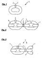
- FIGS. 1 to 3 shown chain links or constructed of these chain pieces illustrate the prior art.
- Fig. 1 shows this a pre-bent chain link 1.
- Such chain links 1 can be drawn from wire coils (coils) wire or rods (with wire diameters from about 22 mm), which are then cut on bending machines into individual stubs (pins) and bent into chain links 1, getting produced.
- the end surfaces of the pre-bent chain links 1 are still relatively far apart, so that the individual chain links 1 according to Fig. 1 be hooked into each other to form a chain, after which then the distance between the two end faces 2 of the pre-bent chain link 1 is reduced so that, as in Fig.
- the interconnected chain links 1 can not be separated from each other, because the passage cross-section between the end faces 2 of the open ends of each chain link 1 is too small to allow the full thickness of the bent leg of the hinged adjacent members pass.
- the chain links 1 of the illustration Fig. 2 are then joined together by subsequent welding of the respective two end faces 2a, 2b of each pre-bent chain link 1 by means of resistance butt welding or flash butt welding, whereby then the finished welded chain 3 results, as in Fig. 3 is shown, in which the welds 4 are visible.
- a pre-bent chain link 1 as in principle in Fig. 1 is shown, requires a bending process with which only round or profile wires can be processed with simple cross-sections to a welded chain 3. Chain links with more complicated cross sections or different cross sections can not be produced with such a bending process. Because of the above-mentioned welding method, only certain alloys and metals can be used, in particular steels with carbon contents of more than 0.25% are no longer weldable with said fusion welding because of the risk of cracking then occurring.
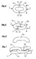
- the chain link 1 off Fig. 5 consists of two half-links 5a, 5b of the Fig. 4 already known type, but here not the half-member 5a held and the half-link 5b in the in Fig. 4 shown in the common clamping plane of the two half-links is oscillated, but now even both half-links 5a, 5b each perpendicular to their Aufspannbenen and in opposite movement reciprocate back and forth to in this way at the flat end surfaces 2a, 2b and 2a ', 2b ', which in turn are pressed against each other to produce the desired welding temperature over the entire surface extension of each end face 2a, 2b, 2a', 2b 'away.
- These opposing linear vibrations are in Fig. 5 illustrated by the arrows F and F '.
- the Fig. 6 now shows another form for a chain link section 5a, again in the form of a half-link, which corresponds to the division of a chain link 1 in a center plane perpendicular to the Aufspannbene.
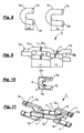
- FIG. 8 two chain link sections 5a and 5a '(in each case in the form of a half-link) shown, which are provided for the production of chain links 1 with unequal size pitch, which alternately in the course of the chain accordingly Fig. 9 be connected to each other. While that in Fig. 8 Links shown chain link portion 5a is provided for the preparation of a chain link 1 with the pitch t2, which is in Fig. 8 Right chain link section 5a 'for the production of a chain link 1' with a larger pitch t1 determined. It results in a chain 3, as in Fig. 9 is shown, in which the individual chain links 1 and 1 'have alternately unequal length leg lengths.
- Another form of chain link section 5a is shown in FIG Fig. 10 shown.
- the outer contour of the chain links 1, which can be produced from such chain link sections 5a, is rectangular.
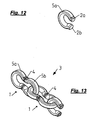
- Fig. 12 another variant of a chain link section 5a is shown, which has a bending-favorable, curved shape with respect to the subsequent stress distribution in the chain, with the tensile stresses in the Randfasem of the chain link can be reduced.
- Fig. 13 shows a chain 3 constructed from such chain link sections 5a.
- chain link sections 5a, 5b shown there have a respective non-circular profile cross section at the end surfaces 2a, 2b when the material strand is used. But even this is only by way of example, it could of course also here profile cross sections be used, which show any rounded, in particular an oval or circular, cross-sectional shape.
- the chain link 1 can still be composed in a variety of other ways from two differently designed chain link sections, which can be connected to each other by linear friction welding.
- the mutually rubbing end surfaces 2a, 2b, 2a ', 2b' also different than just be formed (in a mutually complementary shape): however, their shape must ensure that frictional contact over the respective entire end face (when the two end surfaces to be welded together aligned with each other) and also the relative movement of the end surfaces can be performed unhindered each other in continuing existing frictional contact.
- profile cross sections for such interconnected by means of linear friction welding chain link sections can be used without in this case, the restrictions to be met in the selection of the profile cross-section are to be observed in vorzubiegenden sections (as in the prior art).
Priority Applications (1)
| Application Number | Priority Date | Filing Date | Title |
|---|---|---|---|
| PL08864551T PL2219803T3 (pl) | 2007-12-20 | 2008-12-18 | Sposób wytwarzania zgrzewanych łańcuchów okrągłych i profilowych, ogniwo łańcucha do łańcucha okrągłego lub profilowego oraz łańcuch okrągły lub profilowy zbudowany z takich ogniw łańcucha |
Applications Claiming Priority (2)
| Application Number | Priority Date | Filing Date | Title |
|---|---|---|---|
| DE102007061512A DE102007061512A1 (de) | 2007-12-20 | 2007-12-20 | Verfahren zur Herstellung geschweißter Rund- und Profilketten, Kettenglied für eine Rund- oder Profilkette sowie aus solchen Kettengliedern aufgebaute Rund- oder Profilkette |
| PCT/EP2008/010842 WO2009080289A1 (de) | 2007-12-20 | 2008-12-18 | Verfahren zur herstellung geschweisster rund- und profilketten, kettenglied für eine rund- oder profilkette sowie aus solchen kettengliedern aufgebaute rund- oder profilkette |
Publications (2)
| Publication Number | Publication Date |
|---|---|
| EP2219803A1 EP2219803A1 (de) | 2010-08-25 |
| EP2219803B1 true EP2219803B1 (de) | 2011-08-24 |
Family
ID=40445767
Family Applications (1)
| Application Number | Title | Priority Date | Filing Date |
|---|---|---|---|
| EP08864551A Active EP2219803B1 (de) | 2007-12-20 | 2008-12-18 | Verfahren zur herstellung geschweisster rund- und profilketten, kettenglied für eine rund- oder profilkette sowie aus solchen kettengliedern aufgebaute rund- oder profilkette |
Country Status (9)
| Country | Link |
|---|---|
| US (1) | US8186141B2 (ja) |
| EP (1) | EP2219803B1 (ja) |
| JP (1) | JP2011506100A (ja) |
| CN (1) | CN101918159A (ja) |
| AT (1) | ATE521434T1 (ja) |
| DE (1) | DE102007061512A1 (ja) |
| ES (1) | ES2368595T3 (ja) |
| PL (1) | PL2219803T3 (ja) |
| WO (1) | WO2009080289A1 (ja) |
Families Citing this family (24)
| Publication number | Priority date | Publication date | Assignee | Title |
|---|---|---|---|---|
| US20100212783A1 (en) * | 2005-04-13 | 2010-08-26 | Mccauley John J | Flail chain |
| JP5778790B2 (ja) * | 2011-03-07 | 2015-09-16 | ペヴァック・オーストリア・ゲゼルシャフト・ミット・ベシュレンクテル・ハフツングPewag Austria Gmbh | 長円形状のプロファイル付き鎖環からなるチェーン及びこのタイプのチェーンを製造する方法 |
| CN102513786A (zh) * | 2011-12-03 | 2012-06-27 | 江苏欧玛机械有限公司 | 一种高性能圆环链的制备方法 |
| CN102423841A (zh) * | 2011-12-03 | 2012-04-25 | 江苏欧玛机械有限公司 | 一种重型吊装用圆环链的制备方法 |
| CN102562946A (zh) * | 2011-12-03 | 2012-07-11 | 江苏欧玛机械有限公司 | 一种高性能圆环链 |
| CN102434630A (zh) * | 2011-12-03 | 2012-05-02 | 江苏欧玛机械有限公司 | 一种重型吊装用圆环链 |
| CN102430695A (zh) * | 2011-12-03 | 2012-05-02 | 江苏欧玛机械有限公司 | 一种高新型圆环链的制备方法 |
| WO2013085942A1 (en) * | 2011-12-05 | 2013-06-13 | Apci, Llc | Linear friction welding method |
| US20140311872A1 (en) * | 2013-04-18 | 2014-10-23 | Spiroflow Systems, Inc. | Cable chain with molded flights for tubular drag conveyor |
| CA2993353C (en) | 2015-08-07 | 2021-12-07 | Peerless Chain Company | Debarking chain having bent links |
| DE102015122314B3 (de) | 2015-12-18 | 2016-12-15 | Pewag Austria Gmbh | Linearreibschweißmaschine |
| DE102016218913A1 (de) | 2016-09-29 | 2018-03-29 | Rud Ketten Rieger & Dietz Gmbh U. Co. Kg | Reibverschweißtes Stegelement für ein Reifennetz |
| DE102016226049A1 (de) * | 2016-12-22 | 2018-06-28 | Rud Ketten Rieger & Dietz Gmbh U. Co. Kg | Kettenglied mit reibverschweißtem Traktionselement, Verfahren zu seiner Herstellung und Gleitschutz- oder Reifenschutzvorrichtung mit einem solchen Kettenglied |
| CN106808082B (zh) * | 2017-01-19 | 2019-12-17 | 中冶赛迪工程技术股份有限公司 | 一种无头轧制中间坯连接方法及系统 |
| CN106826244A (zh) * | 2017-01-19 | 2017-06-13 | 中冶赛迪工程技术股份有限公司 | 一种中间坯连接装置及系统 |
| CN106694553B (zh) * | 2017-01-19 | 2019-09-06 | 中冶赛迪工程技术股份有限公司 | 一种中间坯连接设备及系统 |
| CN106624341B (zh) * | 2017-01-19 | 2019-12-10 | 中冶赛迪工程技术股份有限公司 | 一种中间坯连接方法 |
| FI20175538A1 (en) * | 2017-06-12 | 2018-12-13 | Boldan Oy | Cleaning device for cleaning the inside of outlet or sewer pipes and method for making a chain for a cleaning device intended for cleaning the inside of outlet or sewer pipes |
| CN107963397B (zh) * | 2017-11-22 | 2020-07-07 | 营口康辉石化有限公司 | 一种连接管链输送机链板的环链 |
| CN108559920B (zh) * | 2017-12-27 | 2020-01-03 | 山东华源索具有限公司 | G100级方链条的制备方法 |
| CN108436025B (zh) * | 2018-02-05 | 2023-10-17 | 老凤祥东莞珠宝首饰有限公司 | 超薄镂空链条一体成型机 |
| USD934140S1 (en) * | 2020-03-30 | 2021-10-26 | William A. Collins | Chain steering wheel cover |
| USD986104S1 (en) * | 2020-09-23 | 2023-05-16 | Vhernier S.P.A. | Set of chain links for jewelry |
| CN113909673B (zh) * | 2021-11-09 | 2023-08-15 | 浙江同济科技职业学院 | 一种钢筋对焊机 |
Family Cites Families (17)
| Publication number | Priority date | Publication date | Assignee | Title |
|---|---|---|---|---|
| DE8209525U1 (de) | 1982-07-22 | Rud-Kettenfabrik Rieger & Dietz Gmbh U. Co, 7080 Aalen | Reifenkette | |
| US2144319A (en) | 1938-03-26 | 1939-01-17 | S G Taylor Chain Co | Method of making welded chain |
| US2359324A (en) * | 1942-07-14 | 1944-10-03 | Progressive Welder Company | Apparatus for welding |
| GB605645A (en) | 1946-01-02 | 1948-07-28 | Humphrey George Taylor | Improvements in chain links |
| GB870742A (en) | 1958-07-04 | 1961-06-21 | Asea Ab | Method for manufacturing welded chain-links |
| DE2915418A1 (de) | 1979-04-17 | 1980-10-30 | Siemens Ag | Verfahren zum verbinden von werkstuecken aus werkstoffen mit stark unterschiedlichen schmelzpunkten |
| JPS5752545A (en) * | 1980-09-17 | 1982-03-29 | Nippon Chain Anker Kk | Production of chain link |
| DE3212360C1 (de) | 1982-03-31 | 1983-07-28 | Rud-Kettenfabrik Rieger & Dietz Gmbh U. Co, 7080 Aalen | Verfahren zum Herstellen von aus verschweißten Gliedern bestehenden Ketten, insbesondere Reifenketten |
| JPS5942154A (ja) * | 1982-08-31 | 1984-03-08 | Takahiro Ito | タイヤチエ−ンの製造方法 |
| SU1181828A1 (ru) * | 1984-03-13 | 1985-09-30 | Производственное Объединение "Челябинский Тракторный Завод Им.В.И.Ленина" | Способ сварки трением |
| SE455273B (sv) * | 1985-10-08 | 1988-07-04 | Ssab Svenskt Stal Ab | Sett att friktionssvetsa ihop lenkarna i en stalketting |
| JPH09225572A (ja) * | 1996-02-22 | 1997-09-02 | Daido Steel Co Ltd | 難加工合金製溶接リングの製造方法 |
| DE10110896A1 (de) * | 2000-03-24 | 2001-10-31 | Luk Lamellen & Kupplungsbau | Laschenkette |
| AT413346B (de) | 2003-03-21 | 2006-02-15 | Voestalpine Schienen Gmbh | Vorrichtung und verfahren zum verbinden der stirnseiten von teilen |
| DE10333783A1 (de) | 2003-07-24 | 2005-02-17 | Multi Orbital Systems Gmbh | Orbital-Reibschweissverfahren und Vorrichtung zur Durchführung des Verfahrens |
| DE202004021736U1 (de) | 2004-09-10 | 2010-10-21 | J.D. Theile Gmbh & Co. Kg | Gliederkette |
| DE202004014062U1 (de) | 2004-09-10 | 2004-11-11 | J. D. Theile Gmbh & Co. Kg | Gliederkette |
-
2007
- 2007-12-20 DE DE102007061512A patent/DE102007061512A1/de not_active Withdrawn
-
2008
- 2008-12-18 CN CN2008801214636A patent/CN101918159A/zh active Pending
- 2008-12-18 WO PCT/EP2008/010842 patent/WO2009080289A1/de active Application Filing
- 2008-12-18 JP JP2010538464A patent/JP2011506100A/ja active Pending
- 2008-12-18 EP EP08864551A patent/EP2219803B1/de active Active
- 2008-12-18 PL PL08864551T patent/PL2219803T3/pl unknown
- 2008-12-18 AT AT08864551T patent/ATE521434T1/de active
- 2008-12-18 US US12/809,811 patent/US8186141B2/en active Active
- 2008-12-18 ES ES08864551T patent/ES2368595T3/es active Active
Also Published As
| Publication number | Publication date |
|---|---|
| PL2219803T3 (pl) | 2012-03-30 |
| JP2011506100A (ja) | 2011-03-03 |
| ES2368595T3 (es) | 2011-11-18 |
| WO2009080289A1 (de) | 2009-07-02 |
| ATE521434T1 (de) | 2011-09-15 |
| CN101918159A (zh) | 2010-12-15 |
| DE102007061512A1 (de) | 2009-07-30 |
| US8186141B2 (en) | 2012-05-29 |
| EP2219803A1 (de) | 2010-08-25 |
| US20100269479A1 (en) | 2010-10-28 |
Similar Documents
| Publication | Publication Date | Title |
|---|---|---|
| EP2219803B1 (de) | Verfahren zur herstellung geschweisster rund- und profilketten, kettenglied für eine rund- oder profilkette sowie aus solchen kettengliedern aufgebaute rund- oder profilkette | |
| EP2683964B1 (de) | Aus ovalen profilkettengliedern bestehende kette und verfahren zur herstellung einer solchen | |
| DE102010041791B4 (de) | Fahrzeugbauteil | |
| EP1948960B1 (de) | Blattfeder aus einem faserverbundwerkstoff | |
| EP1814748B1 (de) | Verfahren zum herstellen von geteilten rohrstabilisatoren mit schwenkmotor | |
| EP1292423B1 (de) | Verfahren zur herstellung einer nocke für eine nockenwelle | |
| DE3841205C2 (ja) | ||
| WO1995014851A1 (de) | Einstückige hohle nockenwelle und verfahren zu ihrer herstellung | |
| EP3118421B1 (de) | Variable turbinen- oder verdichtergeometrie für einen abgasturbolader | |
| DE102020101851B4 (de) | Federbeingabel sowie Verfahren zur Herstellung einer Federbeingabel | |
| DE102008024585B4 (de) | Federelement für eine Feder-Dämpfer-Anordnung | |
| DE60124330T2 (de) | Hohle Zahnstange und ihr Herstellungsverfahren | |
| EP3535072B1 (de) | Verfahren zur herstellung einer flachgliederkette | |
| DE102010027182A1 (de) | Rohrförmiges Bauteil aus miteinander im Stumpfstoß verschweißten Metallrohren unterschiedlicher Wandstärke und Verfahren zu dessen Herstellung | |
| WO2007006612A1 (de) | Gliederkette sowie verfahren zum herstellen einer gliederkette | |
| DE102011080266A1 (de) | Verfahren zur formschlüssigen Verbindung zweier zumindest teilweise ineinander angeordneter Rohrabschnitte und Verbindungselement zur winkligen Verbindung zweier Rohrabschnitte | |
| DE102017215171A1 (de) | Verfahren zur Herstellung eines Fahrzeuglenkers für eine Radaufhängung sowie Fahrzeuglenker | |
| DE102009017571A1 (de) | Verfahren und Einrichtung zur Herstellung von Rohrbögen oder Rohrbogensegmenten durch Umformen | |
| WO2016029906A1 (de) | Hybridkettenkratzer sowie verfahren zu dessen herstellung | |
| DE102015214248A1 (de) | Verbindungsrohr, Lenk- oder Spurstange mit einem solchen Verbindungsrohr und Verfahren zur Herstellung eines solchen Verbindungsrohres | |
| EP2979773B1 (de) | Gelenkgehäuse für eine Spurstange und Verfahren zu seiner Herstellung | |
| EP3139778B1 (de) | Formbügel für ein damenbekleidungsstück | |
| DE102012005863A1 (de) | Verfahren zur Herstellung eines Leichtmetall umfassenden Bauteils | |
| DE102008050418A1 (de) | Mehrteiliges Profilbauteil und Verfahren zur Herstellung desselben | |
| DE102006031503B4 (de) | Verfahren und Vorrichtung zum Biegen von Hohlprofilen mit minimalem Biegeradius |
Legal Events
| Date | Code | Title | Description |
|---|---|---|---|
| PUAI | Public reference made under article 153(3) epc to a published international application that has entered the european phase |
Free format text: ORIGINAL CODE: 0009012 |
|
| 17P | Request for examination filed |
Effective date: 20100519 |
|
| AK | Designated contracting states |
Kind code of ref document: A1 Designated state(s): AT BE BG CH CY CZ DE DK EE ES FI FR GB GR HR HU IE IS IT LI LT LU LV MC MT NL NO PL PT RO SE SI SK TR |
|
| AX | Request for extension of the european patent |
Extension state: AL BA MK RS |
|
| DAX | Request for extension of the european patent (deleted) | ||
| GRAP | Despatch of communication of intention to grant a patent |
Free format text: ORIGINAL CODE: EPIDOSNIGR1 |
|
| GRAS | Grant fee paid |
Free format text: ORIGINAL CODE: EPIDOSNIGR3 |
|
| GRAA | (expected) grant |
Free format text: ORIGINAL CODE: 0009210 |
|
| AK | Designated contracting states |
Kind code of ref document: B1 Designated state(s): AT BE BG CH CY CZ DE DK EE ES FI FR GB GR HR HU IE IS IT LI LT LU LV MC MT NL NO PL PT RO SE SI SK TR |
|
| REG | Reference to a national code |
Ref country code: GB Ref legal event code: FG4D Free format text: NOT ENGLISH |
|
| REG | Reference to a national code |
Ref country code: CH Ref legal event code: NV Representative=s name: KELLER & PARTNER PATENTANWAELTE AG Ref country code: CH Ref legal event code: EP |
|
| REG | Reference to a national code |
Ref country code: IE Ref legal event code: FG4D Free format text: LANGUAGE OF EP DOCUMENT: GERMAN |
|
| REG | Reference to a national code |
Ref country code: NL Ref legal event code: T3 |
|
| REG | Reference to a national code |
Ref country code: ES Ref legal event code: FG2A Ref document number: 2368595 Country of ref document: ES Kind code of ref document: T3 Effective date: 20111118 |
|
| REG | Reference to a national code |
Ref country code: DE Ref legal event code: R096 Ref document number: 502008004622 Country of ref document: DE Effective date: 20111124 |
|
| LTIE | Lt: invalidation of european patent or patent extension |
Effective date: 20110824 |
|
| PG25 | Lapsed in a contracting state [announced via postgrant information from national office to epo] |
Ref country code: FI Free format text: LAPSE BECAUSE OF FAILURE TO SUBMIT A TRANSLATION OF THE DESCRIPTION OR TO PAY THE FEE WITHIN THE PRESCRIBED TIME-LIMIT Effective date: 20110824 Ref country code: PT Free format text: LAPSE BECAUSE OF FAILURE TO SUBMIT A TRANSLATION OF THE DESCRIPTION OR TO PAY THE FEE WITHIN THE PRESCRIBED TIME-LIMIT Effective date: 20111226 Ref country code: HR Free format text: LAPSE BECAUSE OF FAILURE TO SUBMIT A TRANSLATION OF THE DESCRIPTION OR TO PAY THE FEE WITHIN THE PRESCRIBED TIME-LIMIT Effective date: 20110824 Ref country code: LT Free format text: LAPSE BECAUSE OF FAILURE TO SUBMIT A TRANSLATION OF THE DESCRIPTION OR TO PAY THE FEE WITHIN THE PRESCRIBED TIME-LIMIT Effective date: 20110824 Ref country code: NO Free format text: LAPSE BECAUSE OF FAILURE TO SUBMIT A TRANSLATION OF THE DESCRIPTION OR TO PAY THE FEE WITHIN THE PRESCRIBED TIME-LIMIT Effective date: 20111124 Ref country code: SE Free format text: LAPSE BECAUSE OF FAILURE TO SUBMIT A TRANSLATION OF THE DESCRIPTION OR TO PAY THE FEE WITHIN THE PRESCRIBED TIME-LIMIT Effective date: 20110824 Ref country code: IS Free format text: LAPSE BECAUSE OF FAILURE TO SUBMIT A TRANSLATION OF THE DESCRIPTION OR TO PAY THE FEE WITHIN THE PRESCRIBED TIME-LIMIT Effective date: 20111224 |
|
| PG25 | Lapsed in a contracting state [announced via postgrant information from national office to epo] |
Ref country code: SI Free format text: LAPSE BECAUSE OF FAILURE TO SUBMIT A TRANSLATION OF THE DESCRIPTION OR TO PAY THE FEE WITHIN THE PRESCRIBED TIME-LIMIT Effective date: 20110824 Ref country code: GR Free format text: LAPSE BECAUSE OF FAILURE TO SUBMIT A TRANSLATION OF THE DESCRIPTION OR TO PAY THE FEE WITHIN THE PRESCRIBED TIME-LIMIT Effective date: 20111125 Ref country code: LV Free format text: LAPSE BECAUSE OF FAILURE TO SUBMIT A TRANSLATION OF THE DESCRIPTION OR TO PAY THE FEE WITHIN THE PRESCRIBED TIME-LIMIT Effective date: 20110824 Ref country code: CY Free format text: LAPSE BECAUSE OF FAILURE TO SUBMIT A TRANSLATION OF THE DESCRIPTION OR TO PAY THE FEE WITHIN THE PRESCRIBED TIME-LIMIT Effective date: 20110824 |
|
| REG | Reference to a national code |
Ref country code: IE Ref legal event code: FD4D |
|
| REG | Reference to a national code |
Ref country code: PL Ref legal event code: T3 |
|
| PG25 | Lapsed in a contracting state [announced via postgrant information from national office to epo] |
Ref country code: SK Free format text: LAPSE BECAUSE OF FAILURE TO SUBMIT A TRANSLATION OF THE DESCRIPTION OR TO PAY THE FEE WITHIN THE PRESCRIBED TIME-LIMIT Effective date: 20110824 Ref country code: IE Free format text: LAPSE BECAUSE OF FAILURE TO SUBMIT A TRANSLATION OF THE DESCRIPTION OR TO PAY THE FEE WITHIN THE PRESCRIBED TIME-LIMIT Effective date: 20110824 |
|
| PG25 | Lapsed in a contracting state [announced via postgrant information from national office to epo] |
Ref country code: RO Free format text: LAPSE BECAUSE OF FAILURE TO SUBMIT A TRANSLATION OF THE DESCRIPTION OR TO PAY THE FEE WITHIN THE PRESCRIBED TIME-LIMIT Effective date: 20110824 Ref country code: EE Free format text: LAPSE BECAUSE OF FAILURE TO SUBMIT A TRANSLATION OF THE DESCRIPTION OR TO PAY THE FEE WITHIN THE PRESCRIBED TIME-LIMIT Effective date: 20110824 |
|
| PG25 | Lapsed in a contracting state [announced via postgrant information from national office to epo] |
Ref country code: DK Free format text: LAPSE BECAUSE OF FAILURE TO SUBMIT A TRANSLATION OF THE DESCRIPTION OR TO PAY THE FEE WITHIN THE PRESCRIBED TIME-LIMIT Effective date: 20110824 |
|
| PLBE | No opposition filed within time limit |
Free format text: ORIGINAL CODE: 0009261 |
|
| STAA | Information on the status of an ep patent application or granted ep patent |
Free format text: STATUS: NO OPPOSITION FILED WITHIN TIME LIMIT |
|
| BERE | Be: lapsed |
Owner name: TECHNISCHE UNIVERSITAT GRAZ Effective date: 20111231 Owner name: PEWAG AUSTRIA GMBH Effective date: 20111231 |
|
| PG25 | Lapsed in a contracting state [announced via postgrant information from national office to epo] |
Ref country code: MC Free format text: LAPSE BECAUSE OF NON-PAYMENT OF DUE FEES Effective date: 20111231 |
|
| 26N | No opposition filed |
Effective date: 20120525 |
|
| REG | Reference to a national code |
Ref country code: DE Ref legal event code: R097 Ref document number: 502008004622 Country of ref document: DE Effective date: 20120525 |
|
| PG25 | Lapsed in a contracting state [announced via postgrant information from national office to epo] |
Ref country code: BE Free format text: LAPSE BECAUSE OF NON-PAYMENT OF DUE FEES Effective date: 20111231 |
|
| PG25 | Lapsed in a contracting state [announced via postgrant information from national office to epo] |
Ref country code: MT Free format text: LAPSE BECAUSE OF FAILURE TO SUBMIT A TRANSLATION OF THE DESCRIPTION OR TO PAY THE FEE WITHIN THE PRESCRIBED TIME-LIMIT Effective date: 20110824 |
|
| PG25 | Lapsed in a contracting state [announced via postgrant information from national office to epo] |
Ref country code: LU Free format text: LAPSE BECAUSE OF NON-PAYMENT OF DUE FEES Effective date: 20111218 |
|
| PG25 | Lapsed in a contracting state [announced via postgrant information from national office to epo] |
Ref country code: BG Free format text: LAPSE BECAUSE OF FAILURE TO SUBMIT A TRANSLATION OF THE DESCRIPTION OR TO PAY THE FEE WITHIN THE PRESCRIBED TIME-LIMIT Effective date: 20111124 |
|
| PG25 | Lapsed in a contracting state [announced via postgrant information from national office to epo] |
Ref country code: TR Free format text: LAPSE BECAUSE OF FAILURE TO SUBMIT A TRANSLATION OF THE DESCRIPTION OR TO PAY THE FEE WITHIN THE PRESCRIBED TIME-LIMIT Effective date: 20110824 |
|
| PG25 | Lapsed in a contracting state [announced via postgrant information from national office to epo] |
Ref country code: HU Free format text: LAPSE BECAUSE OF FAILURE TO SUBMIT A TRANSLATION OF THE DESCRIPTION OR TO PAY THE FEE WITHIN THE PRESCRIBED TIME-LIMIT Effective date: 20110824 |
|
| REG | Reference to a national code |
Ref country code: CH Ref legal event code: PCAR Free format text: NEW ADDRESS: EIGERSTRASSE 2 POSTFACH, 3000 BERN 14 (CH) |
|
| REG | Reference to a national code |
Ref country code: FR Ref legal event code: PLFP Year of fee payment: 8 |
|
| REG | Reference to a national code |
Ref country code: FR Ref legal event code: PLFP Year of fee payment: 9 |
|
| REG | Reference to a national code |
Ref country code: FR Ref legal event code: PLFP Year of fee payment: 10 |
|
| REG | Reference to a national code |
Ref country code: CH Ref legal event code: PFA Owner name: TECHNISCHE UNIVERSITAET GRAZ, AT Free format text: FORMER OWNER: TECHNISCHE UNIVERSITAET GRAZ, AT |
|
| PGFP | Annual fee paid to national office [announced via postgrant information from national office to epo] |
Ref country code: AT Payment date: 20201222 Year of fee payment: 13 Ref country code: GB Payment date: 20201223 Year of fee payment: 13 Ref country code: CH Payment date: 20201221 Year of fee payment: 13 |
|
| PGFP | Annual fee paid to national office [announced via postgrant information from national office to epo] |
Ref country code: NL Payment date: 20201221 Year of fee payment: 13 |
|
| REG | Reference to a national code |
Ref country code: CH Ref legal event code: PL |
|
| REG | Reference to a national code |
Ref country code: NL Ref legal event code: MM Effective date: 20220101 |
|
| REG | Reference to a national code |
Ref country code: AT Ref legal event code: MM01 Ref document number: 521434 Country of ref document: AT Kind code of ref document: T Effective date: 20211218 |
|
| GBPC | Gb: european patent ceased through non-payment of renewal fee |
Effective date: 20211218 |
|
| PG25 | Lapsed in a contracting state [announced via postgrant information from national office to epo] |
Ref country code: NL Free format text: LAPSE BECAUSE OF NON-PAYMENT OF DUE FEES Effective date: 20220101 |
|
| PG25 | Lapsed in a contracting state [announced via postgrant information from national office to epo] |
Ref country code: GB Free format text: LAPSE BECAUSE OF NON-PAYMENT OF DUE FEES Effective date: 20211218 Ref country code: AT Free format text: LAPSE BECAUSE OF NON-PAYMENT OF DUE FEES Effective date: 20211218 |
|
| PG25 | Lapsed in a contracting state [announced via postgrant information from national office to epo] |
Ref country code: LI Free format text: LAPSE BECAUSE OF NON-PAYMENT OF DUE FEES Effective date: 20211231 Ref country code: CH Free format text: LAPSE BECAUSE OF NON-PAYMENT OF DUE FEES Effective date: 20211231 |
|
| PGFP | Annual fee paid to national office [announced via postgrant information from national office to epo] |
Ref country code: ES Payment date: 20230227 Year of fee payment: 15 |
|
| PGFP | Annual fee paid to national office [announced via postgrant information from national office to epo] |
Ref country code: IT Payment date: 20231228 Year of fee payment: 16 Ref country code: FR Payment date: 20231221 Year of fee payment: 16 Ref country code: DE Payment date: 20231214 Year of fee payment: 16 Ref country code: CZ Payment date: 20231211 Year of fee payment: 16 |
|
| PGFP | Annual fee paid to national office [announced via postgrant information from national office to epo] |
Ref country code: PL Payment date: 20231208 Year of fee payment: 16 |
|
| PGFP | Annual fee paid to national office [announced via postgrant information from national office to epo] |
Ref country code: ES Payment date: 20240126 Year of fee payment: 16 |