EP2218823B2 - Stabilisierer oder Recycler - Google Patents
Stabilisierer oder Recycler Download PDFInfo
- Publication number
- EP2218823B2 EP2218823B2 EP10000332.6A EP10000332A EP2218823B2 EP 2218823 B2 EP2218823 B2 EP 2218823B2 EP 10000332 A EP10000332 A EP 10000332A EP 2218823 B2 EP2218823 B2 EP 2218823B2
- Authority
- EP
- European Patent Office
- Prior art keywords
- stabiliser
- propelled
- self
- supply tank
- binder
- Prior art date
- Legal status (The legal status is an assumption and is not a legal conclusion. Google has not performed a legal analysis and makes no representation as to the accuracy of the status listed.)
- Active
Links
Images



Classifications
-
- E—FIXED CONSTRUCTIONS
- E01—CONSTRUCTION OF ROADS, RAILWAYS, OR BRIDGES
- E01C—CONSTRUCTION OF, OR SURFACES FOR, ROADS, SPORTS GROUNDS, OR THE LIKE; MACHINES OR AUXILIARY TOOLS FOR CONSTRUCTION OR REPAIR
- E01C21/00—Apparatus or processes for surface soil stabilisation for road building or like purposes, e.g. mixing local aggregate with binder
-
- E—FIXED CONSTRUCTIONS
- E01—CONSTRUCTION OF ROADS, RAILWAYS, OR BRIDGES
- E01C—CONSTRUCTION OF, OR SURFACES FOR, ROADS, SPORTS GROUNDS, OR THE LIKE; MACHINES OR AUXILIARY TOOLS FOR CONSTRUCTION OR REPAIR
- E01C19/00—Machines, tools or auxiliary devices for preparing or distributing paving materials, for working the placed materials, or for forming, consolidating, or finishing the paving
- E01C19/12—Machines, tools or auxiliary devices for preparing or distributing paving materials, for working the placed materials, or for forming, consolidating, or finishing the paving for distributing granular or liquid materials
- E01C19/20—Apparatus for distributing, e.g. spreading, granular or pulverulent materials, e.g. sand, gravel, salt, dry binders
- E01C19/201—Apparatus for distributing, e.g. spreading, granular or pulverulent materials, e.g. sand, gravel, salt, dry binders with driven loosening, discharging or spreading parts, e.g. power-driven, drive derived from road-wheels
- E01C19/202—Apparatus for distributing, e.g. spreading, granular or pulverulent materials, e.g. sand, gravel, salt, dry binders with driven loosening, discharging or spreading parts, e.g. power-driven, drive derived from road-wheels solely rotating, e.g. discharging and spreading drums
- E01C19/2025—Throwers with substantially horizontal axis, e.g. drums or brushes rotated to fling the material at the surface
-
- E—FIXED CONSTRUCTIONS
- E01—CONSTRUCTION OF ROADS, RAILWAYS, OR BRIDGES
- E01C—CONSTRUCTION OF, OR SURFACES FOR, ROADS, SPORTS GROUNDS, OR THE LIKE; MACHINES OR AUXILIARY TOOLS FOR CONSTRUCTION OR REPAIR
- E01C19/00—Machines, tools or auxiliary devices for preparing or distributing paving materials, for working the placed materials, or for forming, consolidating, or finishing the paving
- E01C19/12—Machines, tools or auxiliary devices for preparing or distributing paving materials, for working the placed materials, or for forming, consolidating, or finishing the paving for distributing granular or liquid materials
- E01C19/20—Apparatus for distributing, e.g. spreading, granular or pulverulent materials, e.g. sand, gravel, salt, dry binders
- E01C2019/2055—Details not otherwise provided for
- E01C2019/207—Feeding the distribution means
- E01C2019/2075—Feeding the distribution means with longitudinal conveyor belt
-
- E—FIXED CONSTRUCTIONS
- E01—CONSTRUCTION OF ROADS, RAILWAYS, OR BRIDGES
- E01C—CONSTRUCTION OF, OR SURFACES FOR, ROADS, SPORTS GROUNDS, OR THE LIKE; MACHINES OR AUXILIARY TOOLS FOR CONSTRUCTION OR REPAIR
- E01C19/00—Machines, tools or auxiliary devices for preparing or distributing paving materials, for working the placed materials, or for forming, consolidating, or finishing the paving
- E01C19/12—Machines, tools or auxiliary devices for preparing or distributing paving materials, for working the placed materials, or for forming, consolidating, or finishing the paving for distributing granular or liquid materials
- E01C19/20—Apparatus for distributing, e.g. spreading, granular or pulverulent materials, e.g. sand, gravel, salt, dry binders
- E01C2019/2055—Details not otherwise provided for
- E01C2019/207—Feeding the distribution means
- E01C2019/208—Feeding the distribution means with longitudinal auger
Definitions
- the invention relates to a self-propelled stabilizer or recycler, which has a single rotor housing, in which a single milling / mixing rotor is arranged, and a unit for discharging binders for soil stabilization.
- a powdered binder for example lime or cement
- Typical applications for soil stabilization are the construction of roads or railways as well as industrial areas.
- Stabilizers or recyclers are known with which the binder can both be applied to the soil and can be introduced into the soil immediately after discharge.
- the introduction of the binder immediately after discharge has the advantage that the binder cannot be blown away. This means that the construction machine can be operated with little dust.
- the known stabilizers or recyclers without binder spreaders can in principle be operated in the forward and backward directions.
- stabilizers or recyclers that have a binder spreader only have one working direction, since the binder should always be discharged in front of the milling / mixing rotor. Therefore, the working direction of the stabilizer or recycler equipped with a binder spreader is mentioned below.
- the known stabilizers or recyclers have a chassis that carries a machine frame.
- the running gear has front and rear wheels in the working direction, between which the rotor housing is arranged, which receives the milling / mixing rotor.
- the known stabilizers or recyclers have a drive unit which, in addition to the drive motor, comprises further units which are required for driving the construction machine itself and for driving the milling / mixing rotor. These include, for example, hydraulic pumps for operating hydraulic motors with which the wheels of the self-propelled construction machine are driven.
- the unit for discharging the binder of the known stabilizers or recyclers has a storage container for the binder and a metering device for metering the binder.
- Stabilizers or recyclers are known in which the metering device has one or more cellular wheel sluices.
- the known recyclers or stabilizers are characterized in that the rotor housing with the milling / mixing rotor is arranged on the machine frame between the front or rear wheels, the binding agent being discharged in front of the milling / mixing rotor in the working direction.
- the known stabilizers and recyclers are distinguished by the fact that the storage container for the binder is arranged essentially in front of the milling / mixing rotor in the working direction.
- the EP 1 012 396 B1 describes a stabilizer or recycler which has a unit for discharging binders.
- the funnel-shaped storage container for the binder has a lower section which is arranged between the front wheels and the milling and mixing rotor, and an upper section which is arranged above the milling and mixing rotor.
- the cellular wheel sluice for metering the binder is arranged at the outlet of the lower section of the storage container.
- the problem arises of accommodating the drive unit for the construction machine on the one hand and the storage container for the binder on the other hand on the machine frame. Not only the limited spatial dimensions of the construction machine play a role, but also the weight of the drive unit and the storage container. Since the storage container filled with binder has a relatively high weight, the weight distribution of the construction machine is essentially determined by the arrangement of the storage container on the machine frame.
- the problem of precise metering arises, since the desired spread rate should be adhered to regardless of the speed of the construction machine.
- the rotating cellular wheel transports the binder to a discharge opening, from which the binder falls down under the influence of gravity.
- the flow rate of the binder depends on the chamber volume, the degree of filling and the speed of the cell wheel of the dosing lock.
- a high volumetric dosing accuracy requires that the bulk density is always constant, so that the cellular wheel is always supplied with the same degree of filling.
- the FR 2 743 372 describes a construction machine for terrain cultivation, which has a device for spreading spreading material.
- the spreading agent is provided in a silo which is connected to a hopper of a device for dispensing the spreading agent.
- the construction machine via two working units, which are arranged between the front and rear wheels.
- the front working unit in the working direction serves to remove the material
- the rear working unit serves to distribute the material removed and mixed with the spreading material.
- the spreading material is spread between the front and rear working units.
- the center of gravity of the silo with the spreading material is above the front working unit, while the center of gravity of the hopper is in the working direction behind the axis of rotation of the rotor to distribute the material.
- a spreading machine which has a reservoir for the spreading agent, which has a particularly large capacity and extends over the entire length of the trailer.
- the spreader has an extraction device in the form of a screw conveyor, with which the binder is conveyed to a funnel in order to be able to discharge the binder via a distributor rotor at the rear end of the trailer. It is not evident to what extent the center of gravity of the elongated storage container should be arranged behind the axis of rotation of a milling / mixing rotor in the working direction.
- a device for working the soil which has a device for receiving the soil, a device for applying binder and a mixing device.
- the mixing device comprises a plurality of mixing units arranged one behind the other in the working direction of the construction machine.
- the binder is provided in an elongated storage container and is applied between the device for receiving the soil and the mixing device.
- the US 2004/175234 A1 also describes a construction machine that has a front milling device in the working direction and a rear mixing device.
- the drive unit for the milling device and mixing device is provided at the rear of the machine in the working direction behind these two units.
- Drive unit and binder container are arranged side by side.
- the invention is based on the object of providing a stabilizer or recycler which has a simplified structural design with an improved weight distribution. This object is achieved according to the invention with the features of claim 1.
- Advantageous embodiments of the invention are the subject of the subclaims:
- At least a part, in particular the larger part, of the storage container for the binder i. H. the part of the container with the larger volume for holding the binder, arranged behind the milling / mixing rotor in the working direction.
- the entire storage container it is not absolutely necessary for the entire storage container to be located behind the milling / mixing rotor in the working direction. At least the part of the storage container that has the larger volume should be arranged behind the milling / mixing rotor. Part of the storage container can also be arranged above the milling / mixing rotor. The center of gravity of the storage container is arranged behind the axis of rotation of the milling / mixing rotor in the working direction.
- the drive unit of the construction machine is arranged in front of the milling / mixing rotor.
- the drive unit can be arranged behind a driver's station arranged at the front end of the construction machine or in front of a driver's station arranged in the middle of the machine.
- Sufficient space is available in this area of the machine frame in front of the milling / mixing rotor to accommodate all units of the drive unit.
- the area of the machine frame behind the milling / mixing rotor which is generally shorter than the area in front of the milling / mixing rotor, still provides sufficient space for the arrangement of the storage container.
- the storage container which is filled with binding agent, has a higher weight than the drive unit, an optimal weight distribution results from the length relationships of the machine part in front of and behind the milling / mixing rotor.
- the focus of the construction machine is in the area of the milling / mixing rotor, which is sought in practice.
- the binder is still discharged in front of the milling / mixing rotor. Therefore, the device for the exit of the binder in the working direction is arranged in front of the milling / mixing rotor.
- the binder can also be discharged into the rotor housing.
- This device can be a device which is generally used in the known stabilizers or recyclers. For example, the binder can emerge from a funnel-shaped hood that is equipped with a dust protection device.
- a preferred embodiment of the invention provides that the storage container has an outlet which is provided on a section of the storage container which is at the front in the working direction. If the storage container is funnel-shaped, the outlet should be located on an upper section of the storage container.
- the dosing device for dosing the binder can be arranged directly below the outlet of the storage container. Since the column of binder standing above an outlet at the upper section of the storage container filled with binder is smaller overall than the column which would be above an outlet at the lower section of the storage container, there are fewer fluctuations the density of the binder with which the metering device is loaded. Fluctuations in the density of the binding agent that lead to inaccuracies in the dosage can therefore largely be excluded.
- the unit for dispensing binder preferably has a conveyor device with which the binder can also be conveyed from the lower section to the upper section of a funnel-shaped storage container.
- the conveying device for conveying binders can be designed differently.
- the conveying device has at least one scraper belt which has strips driven by chains or belts for conveying the binder.
- the advantage of the scraper belt is that the binder can be conveyed across the entire working width of the construction machine.
- An alternative embodiment provides one or more screw conveyors. Instead of scraper belts or screw conveyors, a pneumatic conveyor device or another conveyor device known to the person skilled in the art can also be provided.
- the conveyor device for example the scraper belt or the screw conveyor, is arranged at least partially within the storage container, so that the conveyor device and the container form a common assembly.
- the storage container is preferably designed as a funnel-shaped container, so that the binder can collect and be taken up at the bottom of the container.
- the storage container can have a bottom, which is formed by housing parts tapering obliquely towards one another, which extend over part or the entire working width of the machine.
- parts of the side walls can also run obliquely towards one another.
- the storage container it is also possible for the storage container to have a flat bottom.
- the storage container has a front section in the working direction, which is arranged above the milling / mixing rotor, and a rear section in the working direction, which is arranged above the rear wheels or drives, while there is between the milling - / Mixing rotor and the rear wheels or drives extends a central section.
- the rear section of the storage container can end in front of the axis of the rear wheels or can also extend beyond the axis of the rear wheels.
- the middle section of the storage container preferably comprises a relatively low-lying lower section, in which the binder can collect. Consequently, the container has the greatest depth in the area between the milling / mixing rotor and the rear wheels or drives, so that the center of gravity of the storage container lies approximately in this area.
- the unit for dispensing binder has a transport device in order to convey the binder emerging from the metering device to the device at which the metered binder is present the milling / mixing rotor emerges.
- the binder is preferably conveyed by gravity.
- the transport device can be a chute.
- An alternative embodiment provides that the metering device is not arranged directly below the outlet of the storage container, but rather on the device for the exit of the binder.
- This embodiment has the advantage that the distance that the binding agent has to cover after the dosing is relatively small, so that a particularly high dosing accuracy can be achieved.
- the metering device for metering the binder preferably has at least one cellular wheel sluice. It is also possible to provide several, for example three cellular wheel sluices which are arranged one behind the other over the entire working width of the construction machine in the longitudinal direction of the cellular wheel sluices. Individual cellular wheel sluices can also be arranged offset to one another in the longitudinal direction of the recycler or stabilizer. All cellular wheel sluices should be switchable individually. In principle, however, it is also possible for the binder to be metered in using means known from the prior art than using one or more cellular wheel locks.
- a device for distributing the binder is provided in a direction transverse to the longitudinal direction of the machine frame.
- the device for distributing the binder is preferably a distributor screw arranged transversely to the machine frame.
- several distribution screws can also be arranged one behind the other in the longitudinal direction of the distribution screws.
- Individual augers can also be arranged offset to one another in the longitudinal direction of the recycler or stabilizer.
- the storage container for binders has a relatively large volume, which leads to relatively large dimensions in height and / or width, a special permit may be required for driving and / or transporting the construction machine on public roads. Therefore, the aim is that the height and width of the storage container is as small as possible, but this limits the use of the construction machine.
- the storage container is designed as a container, the volume of which is variable.
- the container can be reduced to the size required for a transport permit not yet required. As a result, the transport height and / or transport width of the machine can be reduced.
- the container consists of an upper and lower housing part, which can be moved against each other.
- the connection of the lower and upper housing part can be designed, for example, in the manner of a telescope.
- additional rigid housing parts in the storage container, for. B. be installed between the lower and upper housing part.
- the upper and lower parts of the housing are connected to one another by means of a bellows, which is moved apart or contracted like an accordion to increase or decrease the volume.
- Suitable drives can be provided for this purpose, for example hydraulic or pneumatic drives or electric adjustment motors.
- a preferred embodiment of the invention therefore provides that the storage container is designed as a binder tank that can be inserted into the machine frame.
- the construction machine can thus be provided with or without a binder tank.
- the storage container can either be an integral part of the machine frame or form an interchangeable unit.
- An alternative embodiment provides that at least part of the walls of the storage container are formed by parts of the machine frame, in particular at least parts of the side walls of the storage container can be formed by parts of the machine frame. At least parts of the front and rear walls of the storage container can also be parts of the machine frame.
- the upper housing part and / or the lower housing part of the storage container can be designed as parts that can be mounted on the machine frame, so that the storage container can be retrofitted to the existing machine frame simply by mounting the upper or lower housing part. Since parts of the storage container are already parts of the machine frame, relatively few parts are required to mount the storage container.
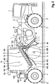
- Fig. 1 shows in a highly simplified schematic representation the essential components of a self-propelled stabilizer or recycler.
- the construction machine has a machine frame 1 which is supported by a chassis 2.
- the undercarriage 2 each has two front wheels 3 in the working direction and two rear wheels 4 in the working direction, which are fastened to front and rear lifting columns 5, 6.
- the front and rear lifting columns 5, 6, which can each be operated independently of one another, are in turn attached to the machine frame 1, so that the height of the machine frame can be adjusted relative to the floor.
- wheels 3, 4 drives, for example drives with rubber bands, can also be provided.
- the driving position 7 of the stabilizer or recycler is arranged in the working direction (driving direction) on the machine frame in front of the front wheels 3 in the present embodiment.
- the control station can also be located in the middle of the machine.
- a rotor housing 8 Between the front and rear wheels 3, 4 there is a rotor housing 8, in which a milling / mixing rotor 9, which is only indicated, is arranged, which rotates about an axis 10 running transversely to the longitudinal direction of the machine frame 1.
- the drive of the milling / mixing rotor can, for. B. mechanically or hydraulically.
- the milling / mixing rotor is provided with tools, not shown, in order to be able to work the soil.
- the rotor housing 8 designed in the manner of a hood for the milling / mixing rotor 9 has front and rear adjustable flaps 8A and 8B in the working direction.
- the milling / mixing rotor 9 can be used to adjust the milling depth on swivel arms 11 which are between the front wheels 3 and the milling / mixing rotor 9 on the machine frame 1 are articulated, the height can be adjusted.
- the drive unit 12 of the stabilizer or recycler is arranged, which comprises an internal combustion engine, not shown in detail, and further units, for example clutches, hydraulic pumps, etc., for driving the hydraulic motors, not shown, for the front and rear wheels 3, 4 and for driving the milling / mixing rotor 9. All components are combined in one unit, which are located between the front wheels 3 and the milling / mixing rotor 9. In the event that the control station should be located in the middle of the machine, the drive unit is located in front of the control station in the working direction.
- the stabilizer or recycler according to the invention has a unit 13 for discharging powdered binder, for example lime or cement, which is to be introduced into the milled soil immediately prior to milling.
- powdered binder for example lime or cement
- the unit 13 for discharging the binder comprises a storage container 14 for receiving the binder, a metering device 15 for metering the binder and a device 20 at which the metered binder exits above the floor in the working direction in front of the milling / mixing rotor 9.
- the individual components of the unit 13 for discharging binder are explained in more detail below.
- the storage container 14 for the binder is designed as a binder tank that can be inserted into the machine frame 1.
- the binder tank thus forms an interchangeable unit.
- drive unit 12 While the drive unit 12 is arranged on the machine frame 1 in the working direction in front of the milling / mixing rotor 9, the storage container 14 is located on the machine frame in the working direction behind the drive unit. Consequently, drive unit 12 and storage container 14 are spatially separated from one another, so that the respective components of both assemblies can each form a spatial unit, which simplifies the construction.
- the storage container 14 is divided into the following sections.
- the storage container 14 has a front section 14A in the working direction, which is arranged above the milling / mixing rotor 9, and has a rear section 14B in the working direction, which is arranged above the rear wheels 4.
- the central section 14C of the storage container 14 extends between the milling / mixing rotor 9 and the rear wheels 4.
- the center of gravity A of the storage container 14 lies between the milling / mixing rotor 9 and the rear wheels 4 of the stabilizers or recyclers, in particular behind the axis of rotation 10 of the Milling / mixing rotor 9.
- the storage container 14 is a metal container designed as a funnel, which has a lower section 14D, on which the walls of the storage container converge obliquely, and an upper section 14E.
- the storage container 14 has an outlet 14F for the binder on the front side of the upper section 14E in the working direction.
- the metering device 15 for metering the binder which has an inlet 15A and an outlet 15B, is located directly below the outlet 14F of the storage container 14.
- the metering device 15 can form a separate assembly or be part of the storage container, so that the Dosing device can be replaced together with the storage container.
- a conveyor 16 which is arranged inside the container, is used to convey the binder from the bottom of the storage container 14 at its lower section 14D to the outlet 14F of the container 14 at its upper section 14E.
- the conveying device 16 is a scraper belt which extends over the entire working width of the stabilizer or recycler and by means of which the binder is conveyed to the outlet 14F along the bottom part 14G of the storage container 14 which runs obliquely in the working direction.
- scraper belts belong to the prior art.
- the scraper belt 16 continuously conveys binder to the higher outlet 14F of the storage container 14, which then falls into the inlet 15A of the metering device 15.
- the binder emerging from the outlet 15B of the metering device 15 is conveyed by a transport device 17 to the device 20, in which the metered binder then trickles onto the floor.
- the transport device 17 is a shaft which runs obliquely downwards in the working direction and connects the outlet of the metering device 15 to the device 20 at which the binder emerges. Instead of one shaft, several shafts can also be arranged distributed across the longitudinal direction of the construction machine.
- the individual shafts can e.g. B. each be formed from a tube or a hose.
- the device 20 for the exit of the binder is a hood which extends over the working width of the machine and is open on the underside.
- a dust protection device in the form of hanging rags can be provided on the hood, but these are only shown in a hint.
- the metering device 15 comprises a metering sluice which extends over the working width of the machine and which has a rotating cellular wheel 15C for metering the binder.
- Cellular wheel locks of this type belong to the prior art.
- several rotary valves arranged one behind the other transversely to the working direction can also be provided.
- three cellular wheel sluices to be operated separately from one another be provided, each covering a third of the total width.
- a cellular wheel sluice can also be provided, which is loaded with binding agent only over a predetermined part of the maximum working width.
- the working width can be changed, for example, with adjustable flaps or sheets that can hold back binders.
- the storage container 14 for the binder consists of a lower housing part 14H and an upper housing part 14I, which are tightly connected to one another via a bellows 14J, so that the volume of the housing is variable.
- Fig. 1 shows the position in which the bellows has moved together like an accordion. In this case, the stabilizer or recycler has only a small overall height.
- Fig. 2 shows the case in which the bellows 14J is extended, so that a much larger volume is available for the binder. If the bellows is retracted, the construction machine cannot make a special permit for transport due to the transport height alone. A volume of, for example, approximately 10 m 3 is available in the extended storage container 14 for the operation of the machine.
- Fig. 3 shows an alternative embodiment of the stabilizer or recycler according to the invention, which differs from that with reference to the Figures 1 and 2nd described embodiment differs by the arrangement of the metering device 15. While the metering device 15 in the exemplary embodiment differs from the Figures 1 and 2nd is located directly below the outlet 14F of the storage container 14, the metering device 15 in the embodiment of FIG Fig. 3 arranged immediately above the device 20 at which the binder emerges. The metering device 15 is therefore located at the lower end of the chute 17. Otherwise, the two exemplary embodiments do not differ from one another. For this reason, the parts that correspond to one another are identified by the same reference symbols.
- Fig. 4 shows another alternative embodiment of the stabilizer or recycler, which differs from that with reference to FIG Figures 1 and 2nd described embodiment differs in that instead of a scraper belt a screw conveyor 16 is provided for conveying the binder to the outlet 14F of the storage container 14.
- screw conveyors are known to the person skilled in the art.
- a plurality of screw conveyors can be provided which are distributed over the working width of the machine. Since, in contrast to a conveyor belt, a conveyor screw can only convey binder over a limited part of the working width, the alternative embodiment has a device 18 with which the binding agent falling off the conveyor screw 16 extends over the entire working width or part of the working width of the construction machine can be distributed before it falls into the metering device 15.
- the device for distributing the binder is preferably a distributor screw 18 arranged above the inlet 15A of the metering device 15, the longitudinal axis of which extends transversely to the longitudinal direction of the machine frame 1.
- the corresponding parts are again identified by the same reference numerals.
- Such a device for distributing the binder in the transverse direction can also be used in the embodiments with a scraper belt ( 1 to 3 ) be advantageous in order to achieve the most uniform possible loading of the metering device over the entire working width
- Fig. 5 shows a side view of another embodiment of the stabilizer or recycler, which differs from the previously described exemplary embodiments in that the reservoir 14 for the binder does not form an interchangeable unit, but is an integral part of the machine frame 1.
- the lower housing part 14H of the storage container 14 is at least partially part of the machine frame 1, the machine frame 1 forming the two side walls 15K of the lower housing part. That too Fig. 5
- the front and rear walls of the storage container 14, which cannot be seen, can be part of a cross strut of the machine frame 1.
- the machine frame 1 is designed in the rear part of the stabilizer or recycler in such a way that the upper housing part 14I with the bellows 14J can be placed on the machine frame 1.
- the upper housing part 14I thus forms the lid of the storage container.
- the machine frame is formed in the rear part of the stabilizer or recycler such that a housing part 14L forming the bottom of the storage container 14 can be mounted on the side walls 15K of the machine frame. This makes it possible to deliver construction machines of the type mentioned with or without a storage container.
- Fig. 5 shows in side view also from the Figures 1 to 4 Components of the construction machine which cannot be seen, for example hydraulic cylinder arrangements 19, but which are not important for the present invention.
- Fig. 6 shows an embodiment of a stabilizer or recycler, which differs from the above-described embodiments in that the storage container 14 does not have a bottom part which runs obliquely in the working direction, but a bottom part 14G which is horizontal in the working direction when the construction machine is standing on a horizontal floor. Consequently, in this embodiment, the Outlet 14F of the storage container 14 is no higher than the bottom part thereof when the construction machine is on a horizontal floor. The scraper belt 16 thus also runs in the horizontal direction.
- the scraper belt 16 which extends over the entire working width of the construction machine, conveys the binder continuously to the outlet 14F of the storage container 14, from which the binder falls via the chute 17 into the inlet 15A of the metering device 15, the outlet 15B of which is arranged above the device 20, at which the binder finally exits in front of the milling / mixing rotor 9.
- the embodiment corresponds to Fig. 6 the embodiment of Fig. 3 .
- the two exemplary embodiments do not differ from one another. For this reason, the parts that correspond to one another are again identified by the same reference symbols.
- a storage container can also be provided, the housing base of which has a flat section, which is followed by sections which run obliquely upward transversely to the longitudinal direction of the construction machine.
- a conveyor screw 16 which extends in the vehicle longitudinal direction over the flat section of the floor, is suitable as the conveyor device 16.
Landscapes
- Engineering & Computer Science (AREA)
- Architecture (AREA)
- Civil Engineering (AREA)
- Structural Engineering (AREA)
- Road Paving Machines (AREA)
- Road Repair (AREA)
- Filling Or Emptying Of Bunkers, Hoppers, And Tanks (AREA)
- Preparation Of Clay, And Manufacture Of Mixtures Containing Clay Or Cement (AREA)
- Accessories For Mixers (AREA)
Description
- Die Erfindung betrifft einen selbstfahrenden Stabilisierer oder Recycler, der über ein einziges Rotorgehäuse, in dem ein einziger Fräs-/Mischrotor angeordnet ist, und eine Einheit zum Austragen von Bindemittel für die Bodenstabilisierung verfügt.
- Zur Verbesserung oder Verfestigung von Böden ist es bekannt, ein pulverförmiges Bindemittel, beispielsweise Kalk oder Zement, in den Boden einzubringen, um dessen Einbaufähigkeit und Tragfähigkeit zu erhöhen. Typische Anwendungsfälle für die Bodenstabilisierung sind der Bau von Straßen oder Schienenwegen sowie Industrieflächen.
- Es sind Stabilisierer oder Recycler bekannt, mit denen das Bindemittel sowohl auf den Boden aufgebracht als auch unmittelbar nach dem Austragen in den Boden eingebracht werden kann. Das Einbringen des Bindemittels unmittelbar nach dem Austragen hat den Vorteil, dass das Bindemittel nicht verweht werden kann. Daher ist ein staubarmer Betrieb der Baumaschine möglich.
- Die bekannten Stabilisierer oder Recycler ohne Bindemittelstreuer können grundsätzlich in Vorwärts- und Rückwärtrichtung betrieben werden. Stabilisierer oder Recycler allerdings, die über einen Bindemittelstreuer verfügen, haben nur eine Arbeitsrichtung, da das Bindemittel immer vor dem Fräs-/Mischrotor ausgetragen werden soll. Daher wird nachfolgend von der Arbeitsrichtung des mit einem Bindemittelstreuer ausgestatteten Stabilisierers oder Recyclers gesprochen.
- Die bekannten Stabilisierer oder Recycler verfügen über ein Fahrwerk, das einen Maschinenrahmen trägt. Das Fahrwerk weist in Arbeitsrichtung vordere und hintere Räder auf, zwischen denen das Rotorgehäuse angeordnet ist, das den Fräs-/Mischrotor aufnimmt. Darüber hinaus weisen die bekannten Stabilisierer oder Recycler eine Antriebseinheit auf, die neben dem Antriebsmotor weitere Aggregate umfasst, die für den Antrieb der Baumaschine selbst und den Antrieb des Fräs-/Mischrotors erforderlich sind. Zu diesen zählen beispielsweise Hydraulikpumpen für den Betrieb von Hydraulikmotoren, mit denen die Räder der selbstfahrenden Baumaschine angetrieben werden.
- Die Einheit zum Austragen des Bindemittels der bekannten Stabilisierer oder Recycler verfügt über einen Vorratsbehälter für das Bindemittel sowie eine Dosiereinrichtung zum Dosieren des Bindemittels. Es sind Stabilisierer oder Recycler bekannt, bei denen die Dosiereinrichtung ein oder mehrere Zellenradschleusen aufweist.
- Die bekannten Recycler oder Stabilisierer zeichnen sich dadurch aus, dass das Rotorgehäuse mit dem Fräs-/Mischrotor am Maschinenrahmen zwischen den vorderen oder hinteren Rädern angeordnet ist, wobei das Bindemittel in Arbeitsrichtung vor dem Fräs-/Mischrotor ausgetragen wird. Darüber hinaus zeichnen sich die bekannten Stabilisierer und Recycler dadurch aus, dass der Vorratsbehälter für das Bindemittel in Arbeitsrichtung im Wesentlichen vor dem Fräs-/Mischrotor angeordnet ist.
- Die
EP 1 012 396 B1 beschreibt einen Stabilisierer oder Recycler, der über eine Einheit zum Austragen von Bindemitteln verfügt. Der trichterförmige Vorratsbehälter für das Bindemittel weist einen unteren Teilabschnitt auf, der zwischen den Vorderrädern und dem Fräs- und Mischrotor angeordnet ist, und einen oberen Teilabschnitt auf, der oberhalb des Fräs- und Mischrotors angeordnet ist. An dem Auslass des unteren Teilabschnitts des Vorratsbehälters ist die Zellenradschleuse zum Dosieren des Bindemittels angeordnet. - Bei der Konstruktion von Stabilisierern oder Recyclern mit einer Einheit zum Austragen von Bindemittel stellt sich das Problem, in dem oder am Maschinenrahmen die Antriebseinheit für die Baumaschine einerseits und den Vorratsbehälter für das Bindemittel andererseits unterzubringen. Dabei spielen nicht nur die begrenzten räumlichen Abmessungen der Baumaschine eine Rolle, sondern auch das Gewicht der Antriebseinheit sowie des Vorratsbehälters. Da der mit Bindemittel gefüllte Vorratsbehälter ein relativ hohes Gewicht hat, wird die Gewichtsverteilung der Baumaschine wesentlich durch die Anordnung des Vorratsbehälters am Maschinenrahmen bestimmt.
- Beim Austragen des Bindemittels stellt sich das Problem der genauen Dosierung, da die gewünschte Streumenge unabhängig von der Fahrgeschwindigkeit der Baumaschine exakt eingehalten werden soll. Bei den bekannten Zellenradschleusen, die im Allgemeinen bei Stabilisierern oder Recyclern Verwendung finden, transportiert das rotierende Zellenrad das Bindemittel zu einer Ausfallöffnung, aus der das Bindemittel unter dem Einfluss der Schwerkraft nach unten fällt. Der Förderstrom des Bindemittels ist von dem Kammervolumen, dem Füllgrad und der Drehzahl des Zellenrades der Dosierschleuse abhängig. Eine hohe volumetrische Dosierungsgenauigkeit setzt voraus, dass die Schüttgutdichte immer konstant ist, so dass das Zellenrad immer mit gleichem Füllgrad versorgt wird.
- Bei einem Stabilisierer oder Recycler, dessen Zellenradschleuse unterhalb eines trichterförmigen Vorratsbehälters angeordnet ist, kann aber ein gleichbleibender Füllgrad des Zellenrades nicht sichergestellt werden, wenn sich der Behälter entleert. Bei noch vollem Behälter beispielsweise ruht auf dem Zellenrad eine wesentlich größere Masse an Bindemittel als bei schon fast entleertem Behälter, so dass von unterschiedlichen Dichten des Bindemittels bei noch vollem oder fast entleertem Behälter auszugehen ist. Dies kann zu Dosierungenauigkeiten führen.
- Die
FR 2 743 372 - Das in Arbeitsrichtung vordere Arbeitsaggregat dient zum Abtragen des Materials, während das hintere Arbeitsaggregat der Verteilung des abgetragenen und mit dem Streumittel vermischten Materials dient. Das Streumittel wird zwischen dem vorderen und hinteren Arbeitsaggregat ausgebracht. Der Schwerpunkt des Silos mit dem Streumittel liegt oberhalb des vorderen Arbeitsaggregats, während der Schwerpunkt des Fülltrichters in Arbeitsrichtung hinter der Drehachse des Rotors zum Verteilen des Materials liegt.
- Aus der
EP 0 462 899 A1 ist eine Streumaschine bekannt, die über einen Vorratsbehälter für das Streumittel verfügt, der ein besonders großes Fassungsvermögen hat und sich über die gesamte Länge des Anhängers erstreckt. Darüber hinaus weist die Streumaschine eine Extraktionseinrichtung in Form einer Förderschnecke auf, mit der das Bindemittel zu einem Trichter gefördert wird, um das Bindemittel über einen Verteilerrotor am hinteren Ende des Anhängers ausbringen zu können. Es ist nicht ersichtlich, inwieweit der Schwerpunkt des langgestreckten Vorratsbehälters in Arbeitsrichtung hinter der Drehachse eines Fräs-/Mischrotors angeordnet sein sollte. - Aus der
US 4 473 320 A ist eine Vorrichtung zur Bearbeitung des Bodens bekannt, die über eine Einrichtung zum Aufnehmen des Bodens, eine Einrichtung zum Aufbringen von Bindemittel und eine Mischeinrichtung verfügt. Die Mischeinrichtung umfasst mehrere in Arbeitsrichtung der Baumaschine hintereinander angeordnete Mischeinheiten. Das Bindemittel wird in einem langgestreckten Vorratsbehälter bereitgestellt und zwischen der Einrichtung zum Aufnehmen des Bodens und der Mischeinrichtung aufgebracht. DieUS 2004/175234 A1 beschreibt ebenfalls eine Baumaschine, die über eine in Arbeitsrichtung vordere Fräseinrichtung und eine hintere Mischeinrichtung verfügt. Die Antriebseinheit für die Fräseinrichtung und Mischeinrichtung ist am Heck der Maschine in Arbeitsrichtung hinter diesen beiden Aggregaten vorgesehen. Antriebseinheit und Bindemittelbehälter sind nebeneinander angeordnet. - Der Erfindung liegt die Aufgabe zu Grunde, einen Stabilisierer oder Recycler zu schaffen, der einen vereinfachten konstruktiven Aufbau bei einer verbesserten Gewichtsverteilung hat. Die Lösung dieser Aufgabe erfolgt erfindungsgemäß mit den Merkmalen des Anspruchs 1. Vorteilhafte Ausführungsformen der Erfindung sind Gegenstand der Unteransprüche:
- Bei der erfindungsgemäßen Baumaschine ist zumindest ein Teil, insbesondere der größere Teil des Vorratsbehälters für das Bindemittel, d. h. der Teil des Behälters mit dem größeren Volumen zur Aufnahme des Bindemittels, in Arbeitsrichtung hinter dem Fräs-/Mischrotor angeordnet.
- Es ist nicht zwingend erforderlich, dass sich der gesamte Vorratsbehälter in Arbeitsrichtung hinter dem Fräs-/Mischrotor befindet. Zumindest sollte aber der Teil des Vorratsbehälters hinter dem Fräs-/Mischrotor angeordnet sein, der das größere Volumen hat. Dabei kann auch ein Teil des Vorratsbehälters oberhalb des Fräs-/Mischrotors angeordnet sein. Der Schwerpunkt des Vorratsbehälters ist in Arbeitsrichtung hinter der Drehachse des Fräs-/Mischrotors angeordnet.
- Aus der besonderen Anordnung des Vorratsbehälters ergibt sich eine optimale Gewichtsverteilung. Während der mit Bindemittel gefüllte relativ schwere Vorratsbehälter, sich im Wesentlichen hinter dem Fräs-/Mischrotor befindet, ist die Antriebseinheit der Baumaschine vor dem Fräs-/Mischrotor angeordnet. Dabei kann die Antriebseinheit hinter einem am vorderen Ende der Baumaschine angeordneten Fahrstand oder vor einem in der Maschinenmitte angeordneten Fahrstand angeordnet sein. In diesem Bereich des Maschinenrahmens vor dem Fräs-/Mischrotor steht ausreichend Raum zur Verfügung, um sämtliche Aggregate der Antriebseinheit unterzubringen. Der Bereich des Maschinenrahmens hinter dem Fräs-/Mischrotor, der im Allgemeinen kürzer als der Bereich vor dem Fräs-/Mischrotor ist, stellt dabei noch ausreichend Platz für die Anordnung des Vorratsbehälters zur Verfügung. Da der Vorratsbehälter, der mit Bindemittel gefüllt ist, ein höheres Gewicht als die Antriebseinheit hat, ergeben sich aus den Längenverhältnissen des Maschinenteils vor und hinter dem Fräs-/Mischrotor eine optimale Gewichtsverteilung. Der Schwerpunkt der Baumaschine liegt bei einer derartigen Anordnung von Vorratsbehälter und Antriebseinheit zwischen den Vorder- und Hinterrädern im Bereich des Fräs-/Mischrotors, was in der Praxis angestrebt wird.
- Obwohl sich bei der erfindungsgemäßen Baumaschine der Vorratsbehälter hinter dem Fräs-/Mischrotor befindet, wird das Bindemittel weiterhin vor dem Fräs-/Mischrotor ausgetragen. Daher ist die Einrichtung für den Austritt des Bindemittels in Arbeitsrichtung vor dem Fräs-/Mischrotor angeordnet. Dabei kann das Bindemittel auch in das Rotorgehäuse hinein ausgetragen werden. Bei dieser Einrichtung kann es sich um eine Einrichtung handeln, die bei den bekannten Stabilisierern oder Recyclern im Allgemeinen Verwendung findet. Beispielsweise kann das Bindemittel aus einer trichterförmigen Haube austreten, die mit einer Staubschutzeinrichtung ausgestattet ist.
- Eine bevorzugte Ausführungsform der Erfindung sieht vor, dass der Vorratsbehälter einen Auslass aufweist, der an einem in Arbeitsrichtung vorderen Teilabschnitt des Vorratsbehälters vorgesehen ist. Wenn der Vorratsbehälter trichterförmig ausgebildet ist, sollte sich der Auslass an einem oberen Teilabschnitt des Vorratsbehälters befinden. Die Dosiereinrichtung zum Dosieren des Bindemittels kann unmittelbar unterhalb des Auslasses des Vorratsbehälters angeordnet werden. Da die über einem Auslass am oberen Teilabschnitt des mit Bindemittel gefüllten Vorratsbehälters stehende Säule an Bindemittel insgesamt kleiner ist als die Säule, die über einem Auslass am unteren Teilabschnitt des Vorratsbehälters stünde, ergeben sich geringere Schwankungen der Dichte des Bindemittels, mit dem die Dosiereinrichtung beschickt wird. Zu Dosierungenauigkeiten führende Schwankungen der Dichte des Bindemittels sind daher weitgehend auszuschließen.
- Zum Fördern des Bindemittels zu der Dosiereinrichtung verfügt die Einheit zum Austragen von Bindemittel vorzugsweise über eine Fördereinrichtung, mit der das Bindemittel auch von dem unteren Teilabschnitt zu dem oberen Teilabschnitt eines trichterförmigen Vorratsbehälters gefördert werden kann.
- Die Fördereinrichtung zum Fördern von Bindemittel kann unterschiedlich ausgebildet sein. Bei einer bevorzugten Ausführungsform weist die Fördereinrichtung mindestens ein Kratzerband auf, das über mit Ketten oder Bändern angetriebene Leisten zum Fördern des Bindemittels verfügt. Das Kratzerband hat den Vorteil, dass das Bindemittel über die gesamte Arbeitsbreite der Baumaschine gefördert werden kann. Eine alternative Ausführungsform sieht als Fördereinrichtung eine oder mehrere Förderschnecken vor. Anstelle von Kratzerbändern oder Förderschnecken kann aber auch eine pneumatische Fördereinrichtung oder eine andere dem Fachmann bekannte Fördereinrichtung vorgesehen sein.
- Bei einer weiteren bevorzugten Ausführungsform ist die Fördereinrichtung, beispielsweise das Kratzerband oder die Förderschnecke, zumindest teilweise innerhalb des Vorratsbehälters angeordnet, so dass Fördereinrichtung und Behälter eine gemeinsame Baugruppe bilden.
- Der Vorratsbehälter ist vorzugsweise als trichterförmiger Behälter ausgebildet, so dass sich das Bindemittel am Boden des Behälters sammeln und aufgenommen werden kann. Beispielsweise kann der Vorratsbehälter einen Boden aufweisen, der von schräg aufeinander zulaufenden Gehäuseteilen gebildet wird, die sich über einen Teil oder die gesamte Arbeitsbreite der Maschine erstrecken. Es können aber auch Teile der Seitenwände schräg aufeinander zulaufen. Grundsätzlich ist es aber auch möglich, dass der Vorratsbehälter einen flachen Boden aufweist.
- Eine besonders bevorzugte Ausführungsform sieht vor, dass der Vorratsbehälter einen in Arbeitsrichtung vorderen Teilabschnitt aufweist, der oberhalb des Fräs-/ Mischrotors angeordnet ist, und einen in Arbeitsrichtung hinteren Teilabschnitt aufweist, der oberhalb der hinteren Räder oder Laufwerke angeordnet ist, während sich zwischen dem Fräs-/Mischrotor und den hinteren Rädern oder Laufwerken ein mittlerer Teilabschnitt erstreckt. Der hintere Abschnitt des Vorratsbehälters kann vor der Achse der Hinterräder enden oder sich auch bis über die Achse der Hinterräder hinaus erstrecken.
- Der mittlere Teilabschnitt des Vorratsbehälters umfasst vorzugsweise einen relativ tief liegenden unteren Teilabschnitt, in dem sich das Bindemittel sammeln kann. Folglich hat der Behälter in dem Bereich zwischen Fräs-/Mischrotor und den hinteren Rädern oder Laufwerken die größte Tiefe, so dass der Schwerpunkt des Vorratsbehälters in etwa in diesem Bereich liegt.
- Bei der Ausführungsform, bei der die Dosiereinrichtung an dem Vorratsbehälter insbesondere unterhalb des Auslasses des Vorratsbehälters angeordnet ist, weist die Einheit zum Austragen von Bindemittel eine Transporteinrichtung auf, um das aus der Dosiereinrichtung austretende Bindemittel zu der Einrichtung zu befördern, an der das dosierte Bindemittel vor dem Fräs-/Mischrotor austritt. Vorzugsweise wird das Bindemittel aufgrund der Schwerkraft befördert. Beispielsweise kann die Transporteinrichtung ein Fallschacht sein.
- Eine alternative Ausführungsform sieht vor, dass die Dosiereinrichtung nicht unmittelbar unterhalb des Auslasses des Vorratsbehälters, sondern an der Einrichtung für den Austritt des Bindemittels angeordnet ist. Diese Ausführungsform hat den Vorteil, dass die Strecke, die das Bindemittel nach der Dosierung zurücklegen muss, relativ klein ist, so dass sich eine besonders hohe Dosiergenauigkeit erzielen lässt.
- Die Dosiereinrichtung zum Dosieren des Bindemittels weist vorzugsweise mindestens eine Zellenradschleuse auf. Es können auch mehrere, beispielsweise drei Zellenradschleusen vorgesehen sein, die über die gesamte Arbeitsbreite der Baumaschine in Längsrichtung der Zellenradschleusen hintereinander angeordnet sind. Dabei können einzelne Zellenradschleusen auch in Längsrichtung des Recyclers oder Stabilisierers versetzt zueinander angeordnet sein. Sämtliche Zellenradschleusen sollten einzeln zuschaltbar sein. Es ist aber grundsätzlich auch möglich, dass eine Dosierung des Bindemittels mit anderen aus dem Stand der Technik bekannten Mitteln als mit einer oder mehreren Zellenradschleusen erfolgt.
- Für eine möglichst gleichmäßige Beschickung der Dosiervorrichtung ist von Vorteil, wenn eine Einrichtung zum Verteilen des Bindemittels in einer quer zur Längsrichtung des Maschinenrahmens verlaufenden Richtung vorgesehen ist. Vorzugsweise ist die Einrichtung zum Verteilen des Bindemittels eine quer zum Maschinenrahmen angeordnete Verteilerschnecke. Es können aber auch mehrere Verteilerschnecken in Längsrichtung der Verteilerschnecken hintereinander angeordnet sein. Dabei können auch einzelne Verteilerschnecken in Längsrichtung des Recyclers oder Stabilisierers versetzt zueinander angeordnet sein.
- Da der Vorratsbehälter für Bindemittel ein relativ großes Volumen hat, was zu relativ großen Abmessungen in Höhe und/oder Breite führt, kann zum Fahren und/oder Transportieren der Baumaschine auf öffentlichen Straßen eine Sondergenehmigung erforderlich sein. Daher wird angestrebt, dass das Bauhöhe und -breite des Vorratsbehälters möglichst klein ist, wodurch sich aber der Einsatz der Baumaschine einschränkt.
- Dieses Problem wird unabhängig von der Anordnung des Vorratsbehälters dadurch gelöst, dass der Vorratsbehälter als ein Behälter ausgebildet ist, dessen Volumen variabel ist. Für den Fall, dass der Vorratsbehälter nicht mit Bindemittel gefüllt ist, kann der Behälter auf die Größe verkleinert werden, die eine Transportgenehmigung noch nicht erforderlich macht. Dadurch kann die Transporthöhe und/oder Transportbreite der Maschine verringert werden.
- Bei einer bevorzugten Ausführungsform des Vorratsbehälters mit variablem Volumen besteht der Behälter aus einem oberen und unteren Gehäuseteil, die gegeneinander verschoben werden können. Die Verbindung des unteren und oberen Gehäuseteils kann beispielsweise in der Art eines Teleskops ausgebildet sein. Zur Vergrößerung des Volumens können aber auch zusätzliche starre Gehäuseteile in den Vorratsbehälter, z. B. zwischen unterem und oberem Gehäuseteil eingebaut werden.
- Bei einer besonders bevorzugten Ausführungsform sind Gehäuseober- und -unterteil über einen Faltenbalg miteinander verbunden, der zur Vergrößerung bzw. Verkleinerung des Volumens ziehharmonikaartig auseinander- bzw. zusammengefahren wird. Hierzu können geeignete Antriebe vorgesehen sein, beispielsweise hydraulische oder pneumatische Antriebe oder elektrische Verstellmotoren.
- Bei der Fertigung des Stabilisierers oder Recyclers stellt sich ferner das Problem, dass Stabilisierer oder Recycler mit oder ohne Bindemittelstreuer eingesetzt werden, der über einen Vorratsbehälter für das Bindemittel verfügen. Es besteht daher der Wunsch nach einem nachrüstbaren Bindemittelbehälter, der auf eine bestehende Plattform aufgebaut werden kann.
- Eine bevorzugte Ausführungsform der Erfindung sieht daher vor, dass der Vorratsbehälter als ein in den Maschinenrahmen einsetzbarer Bindemitteltank ausgebildet ist. Damit kann die Baumaschine mit oder ohne Bindemitteltank bereitgestellt werden. Der Vorratsbehälter kann also entweder integraler Bestandteil des Maschinenrahmens sein oder eine austauschbare Einheit bilden.
- Eine alternative Ausführungsform sieht vor, dass zumindest ein Teil der Wände des Vorratsbehälters von Teilen des Maschinenrahmens gebildet werden, insbesondere zumindest Teile der Seitenwände des Vorratsbehälters können von Teilen des Maschinenrahmens gebildet werden. Auch zumindest Teile der Vorder- und Rückwand des Vorratsbehälters können Teile des Maschinenrahmens sein. Bei dieser Ausführungsform können das Gehäuseoberteil und/oder das Gehäuseunterteil des Vorratsbehälters als an dem Maschinenrahmen montierbare Teile ausgebildet sein, so dass allein durch die Montage von Gehäuseober- oder -unterteil der Vorratsbehälter an den bestehenden Maschinerahmen nachträglich geschaffen werden kann. Da Teile des Vorratsbehälters bereits Teile des Maschinenrahmens sind, werden verhältnismäßig wenige Teile benötigt, um den Vorratsbehälter zu montieren.
- Im Folgenden werden mehrere Ausführungsbeispiele der Erfindung unter Bezugnahme auf die Zeichnungen näher erläutert.
-
- Fig. 1
- ein erstes Ausführungsbeispiel der erfindungsgemäßen selbstfahrenden Baumaschine in stark vereinfachter schematischer Darstellung,
- Fig. 2
- den Stabilisierer oder Recycler von
Fig. 1 , wobei der Vorratsbehälter für das Bindemittel zur Vergrößerung des Volumens ausgefahren ist, - Fig. 3
- ein weiteres Ausführungsbeispiel des erfindungsgemäßen Stabilisierers oder Recyclers,
- Fig. 4
- ein weiteres Ausführungsbeispiel des erfindungsgemäßen Stabilisierers oder Recyclers,
- Fig. 5
- ein weiteres Ausführungsbeispiel des Stabilisierers oder Recyclers und
- Fig. 6
- ein weiteres Ausführungsbeispiel des Stabilisierers oder Recyclers.
-
Fig. 1 zeigt in stark vereinfachter schematischer Darstellung die wesentlichen Komponenten eines selbstfahrenden Stabilisierers oder Recyclers. Die Baumaschine weist einen Maschinenrahmen 1 auf, der von einem Fahrwerk 2 getragen wird. Das Fahrwerk 2 weist jeweils zwei in Arbeitsrichtung vordere Räder 3 und zwei in Arbeitsrichtung hintere Räder 4 auf, die an vorderen und hinteren Hubsäulen 5, 6 befestigt sind. Die vorderen und hinteren Hubsäulen 5, 6, die jeweils voneinander unabhängig betätigt werden können, sind wiederum am Maschinenrahmen 1 befestigt, so dass der Maschinenrahmen gegenüber dem Boden in der Höhe verstellt werden kann. Anstelle von Rädern 3, 4 können auch Laufwerke, beispielsweise Laufwerke mit Gummibändern vorgesehen sein. - Der Fahrstand 7 des Stabilisierers oder Recyclers ist bei dem vorliegenden Ausführungsbeispiel in Arbeitsrichtung (Fahrtrichtung) am Maschinenrahmen vor den Vorderrädern 3 angeordnet. Der Fahrstand kann aber auch in der Maschinenmitte angeordnet sein. Zwischen den Vorder- und Hinterrädern 3, 4 befindet sich ein Rotorgehäuse 8, in dem ein nur andeutungsweise dargestellter Fräs-/Mischrotor 9 angeordnet ist, der um eine quer zur Längsrichtung des Maschinenrahmens 1 verlaufende Achse 10 rotiert. Der Antrieb des Fräs-/Mischrotors kann z. B. mechanisch oder hydraulisch erfolgen. Der Fräs-/Mischrotor ist mit nicht dargestellten Werkzeugen versehen, um den Boden bearbeiten zu können. Das in der Art einer Haube ausgebildete Rotorgehäuse 8 für den Fräs-/Mischrotor 9 weist in Arbeitsrichtung vordere und hintere verstellbare Klappen 8A und 8B auf. Der Fräs-/Mischrotor 9 kann zur Einstellung der Frästiefe an Schwenkarmen 11, die zwischen den Vorderrädern 3 und dem Fräs-/Mischrotor 9 am Maschinenrahmen 1 angelenkt sind, in der Höhe verstellt werden.
- Hinter dem Fahrstand 7 ist zwischen den Vorderrädern 3 und dem Fräs-/Mischrotor 9 am Maschinenrahmen 1 die Antriebseinheit 12 des Stabilisierers oder Recyclers angeordnet, die einen im Einzelnen nicht dargestellten Verbrennungsmotor sowie weitere Aggregate umfasst, beispielsweise Kupplungen, Hydraulikpumpen etc., die zum Antrieb der nicht dargestellten Hydraulikmotoren für die Vorder- und Hinterräder 3, 4 und zum Antrieb des Fräs-/Mischrotors 9 dienen. Sämtliche Komponenten sind in einer Einheit zusammengefasst, die sich zwischen den Vorderrädern 3 und dem Fräs-/Mischrotor 9 befinden. Für den Fall, dass der Fahrstand in der Maschinenmitte angeordnet sein sollte, befindet sich die Antriebseinheit in Arbeitsrichtung vor dem Fahrstand.
- Der erfindungsgemäße Stabilisierer oder Recycler verfügt über eine Einheit 13 zum Austragen von pulverförmigem Bindemittel, beispielsweise Kalk oder Zement, das unmittelbar vor dem Auffräsen in den aufgefrästen Boden eingebracht werden soll.
- Die Einheit 13 zum Austragen von Bindemittel umfasst einen Vorratsbehälter 14 zur Aufnahme des Bindemittels, eine Dosiereinrichtung 15 zum Dosieren des Bindemittels und eine Einrichtung 20, an der das dosierte Bindemittel in Arbeitsrichtung vor dem Fräs-/Mischrotor 9 über dem Boden austritt. Die einzelnen Komponenten der Einheit 13 zum Austragen von Bindemittel werden nachfolgend näher erläutert.
- Bei dem vorliegenden Ausführungsbeispiel ist der Vorratsbehälter 14 für das Bindemittel als ein Bindemitteltank ausgebildet, der in den Maschinenrahmen 1 eingesetzt werden kann. Somit bildet der Bindemitteltank eine austauschbare Einheit.
- Während die Antriebseinheit 12 am Maschinenrahmen 1 in Arbeitsrichtung vor dem Fräs-/Mischrotor 9 angeordnet ist, befindet sich der Vorratsbehälter 14 am Maschinenrahmen in Arbeitsrichtung hinter der Antriebseinheit. Folglich sind Antriebseinheit 12 und Vorratsbehälter 14 räumlich voneinander getrennt, so dass die jeweiligen Komponenten beider Baugruppen jeweils eine räumliche Einheit bilden können, wodurch sich der konstruktive Aufbau vereinfacht.
- Im Hinblick auf die Anordnung am Maschinenrahmen 1 teilt sich der Vorratsbehälter 14 in die folgenden Teilabschnitte auf. Der Vorratsbehälter 14 weist einen in Arbeitsrichtung vorderen Teilabschnitt 14A auf, der oberhalb des Fräs-/Mischrotors 9 angeordnet ist, und weist einen in Arbeitsrichtung hinteren Teilabschnitt 14B auf, der oberhalb der Hinterräder 4 angeordnet ist. Zwischen dem Fräs-/Mischrotor 9 und den Hinterrädern 4 erstreckt sich der mittlere Teilabschnitt 14C des Vorratsbehälters 14. Der Schwerpunkt A des Vorratsbehälters 14 liegt zwischen dem Fräs-/Mischrotor 9 und den Hinterrädern 4 der Stabilisierers oder Recyclers, insbesondere hinter der Drehachse 10 des Fräs-/Mischrotors 9.
- Der Vorratsbehälter 14 ist bei dem vorliegenden Ausführungsbeispiel ein als Trichter ausgebildeter Metallbehälter, der einen unteren Teilabschnitt 14D, an dem die Wände des Vorratsbehälters schräg aufeinander zulaufen, und einen oberen Teilabschnitt 14E aufweist. An der in Arbeitsrichtung vorderen Seite des oberen Teilabschnitts 14E weist der Vorratsbehälter 14 einen Auslass 14F für das Bindemittel auf.
- Bei dem vorliegenden Ausführungsbeispiel befindet sich die Dosiereinrichtung 15 zum Dosieren des Bindemittels, die einen Einlass 15A und einen Auslass 15B aufweist, unmittelbar unterhalb des Auslasses 14F des Vorratsbehälters 14. Die Dosiereinrichtung 15 kann eine separate Baugruppe bilden oder Teil des Vorratsbehälters sein, so dass die Dosiereinrichtung zusammen mit dem Vorratsbehälter ausgetauscht werden kann.
- Zum Fördern des Bindemittels vom Boden des Vorratsbehälters 14 an dessen unteren Teilabschnitt 14D zum Auslass 14F des Behälters 14 an dessen oberen Teilabschnitt 14E dient eine Fördereinrichtung 16, die innerhalb des Behälters angeordnet ist. Die Fördereinrichtung 16 ist bei dem vorliegenden Ausführungsbeispiel ein sich über die gesamte Arbeitsbreite des Stabilisierers oder Recyclers erstreckendes Kratzerband, mit dem das Bindemittel entlang des in Arbeitsrichtung schräg verlaufenden Bodenteils 14G des Vorratsbehälters 14 zum Auslass 14F gefördert wird. Derartige Kratzerbänder gehören zum Stand der Technik.
- Das Kratzerband 16 fördert kontinuierlich Bindemittel zum höher liegenden Auslass 14F des Vorratsbehälters 14, das dann in den Einlass 15A der Dosiervorrichtung 15 fällt. Das aus dem Auslass 15B der Dosiereinrichtung 15 austretende Bindemittel wird mit einer Transporteinrichtung 17 zu der Einrichtung 20 befördert, in der das dosierte Bindemittel dann auf den Boden rieselt. Die Transporteinrichtung 17 ist ein in Arbeitsrichtung schräg nach unten verlaufender Schacht, der den Auslass der Dosiereinrichtung 15 mit der Einrichtung 20 verbindet, an der das Bindemittel austritt. Anstelle eines Schachts können auch mehrere Schächte quer zur Längsrichtung der Baumaschine verteilt angeordnet sein.
- Die einzelnen Schächte können z. B. jeweils aus einem Rohr oder einem Schlauch gebilde sein. Die Einrichtung 20 zum Austritt des Bindemittels ist eine sich über die Arbeitsbreite der Maschine erstreckende Haube, die an der Unterseite offen ist. An der Haube kann eine Staubschutzeinrichtung in Form von herunterhängenden Lappen vorgesehen sein, die aber nur andeutungsweise dargestellt sind.
- Die Dosiereinrichtung 15 umfasst bei dem vorliegenden Ausführungsbeispiel eine sich über die Arbeitsbreite der Maschine erstreckende Dosierschleuse, die ein rotierendes Zellenrad 15C zum Dosieren des Bindemittels aufweist. Derartige Zellenradschleusen gehören zum Stand der Technik. Anstelle nur einer Zellenradschleuse können aber auch mehrere quer zur Arbeitsrichtung hintereinander angeordnete Zellenradschleusen vorgesehen sein. Beispielsweise können drei getrennt voneinander zu betreibende Zellenradschleusen vorgesehen sein, die jeweils ein Drittel der Gesamtbreite abdecken. Anstelle von drei separaten Zellenradschleusen kann auch eine Zellenradschleuse vorgesehen sein, die nur über einen vorbestimmten Teil der maximalen Arbeitsbreite mit Bindemittel beschickt wird. Die Arbeitsbreite kann beispielsweise mit verstellbaren Klappen oder Blechen, die Bindemittel zurückhalten können, verändert werden.
- Da die vorliegende Anordnung eine kontinuierliche Beschickung der Dosiervorrichtung 15 mit einem Füllgut konstanter Dichte erlaubt, ergibt sich eine besonders hohe volumetrische Dosiergenauigkeit für das Bindemittel.
Bei dem vorliegenden Ausführungsbeispiel besteht der Vorratsbehälter 14 für das Bindemittel aus einem Gehäuseunterteil 14H und einem Gehäuseoberteil 14I, die über einen Faltenbalg 14J dicht miteinander verbunden sind, so dass das Volumen des Gehäuses variabel ist.Fig. 1 zeigt die Position, in der der Faltenbalg ziehharmonikaartig zusammengefahren ist. In diesem Fall hat der Stabilisierer oder Recycler eine nur geringe Bauhöhe. -
Fig. 2 zeigt den Fall, in dem der Faltenbalg 14J ausgefahren ist, so dass ein wesentlich größeres Volumen für das Bindemittel zur Verfügung steht. Bei eingefahrenem Faltenbalg kann die Baumaschine allein aufgrund der Transporthöhe eine Sondergenehmigung für den Transport nicht erforderlich machen. Für den Betrieb der Maschine steht in dem ausgefahrenen Vorratsbehälter 14 ein Volumen von beispielsweise etwa 10 m3 zur Verfügung. -
Fig. 3 zeigt eine alternative Ausführungsform des erfindungsgemäßen Stabilisierers oder Recyclers, die sich von dem unter Bezugnahme auf dieFiguren 1 und2 beschriebenen Ausführungsbeispiel durch die Anordnung der Dosiereinrichtung 15 unterscheidet. Während sich die Dosiereinrichtung 15 bei dem Ausführungsbeispiel von denFiguren 1 und2 unmittelbar unterhalb des Auslasses 14F des Vorratsbehälters 14 befindet, ist die Dosiereinrichtung 15 bei dem Ausführungsbeispiel vonFig. 3 unmittelbar oberhalb der Einrichtung 20 angeordnet, an der das Bindemittel austritt. Die Dosiereinrichtung 15 befindet sich also am unteren Ende des Fallschachtes 17. Ansonsten unterscheiden sich die beiden Ausführungsbeispiele nicht voneinander. Daher werden auch die einander entsprechenden Teile mit den gleichen Bezugszeichen bezeichnet. -
Fig. 4 zeigt eine weitere alternative Ausführungsform des Stabilsierers oder Recylers, die sich von dem unter Bezugnahme auf dieFiguren 1 und2 beschriebenen Ausführungsbeispiel dadurch unterscheidet, dass anstelle eines Kratzerbandes eine Förderschnecke 16 zum Fördern des Bindemittels zum Auslass 14F des Vorratsbehälters 14 vorgesehen ist. Derartige Förderschnecken sind dem Fachmann bekannt. Anstelle nur einer Förderschnecke können auch mehrere über die Arbeitsbreite der Maschine verteilt angeordnete Förderschnecken vorgesehen sein. Da mit einer Förderschnecke im Gegensatz zu einem Förderband nur über einen begrenzten Teil der Arbeitsbreite Bindemittel gefördert werden kann, verfügt die alternative Ausführungsform über eine Einrichtung 18, mit der das von der Förderschnecke 16 abfallende Bindemittel über die gesamte Arbeitsbreite oder einen Teil der Arbeitsbreite der Baumaschine verteilt werden kann, bevor es in die Dosiereinrichtung 15 fällt. Die Einrichtung zum Verteilen des Bindemittels ist vorzugsweise eine oberhalb des Einlasses 15A der Dosiereinrichtung 15 angeordnete Verteilerschnecke 18, deren Längsachse quer zur Längsrichtung des Maschinenrahmens 1 verläuft. Die einander entsprechenden Teile sind wieder mit gleichen Bezugszeichen bezeichnet. Eine derartige Einrichtung zum Verteilen des Bindemittels in Querrichtung kann aber auch bei den Ausführungsformen mit Kratzerband (Fig. 1 bis 3 ) von Vorteil sein, um eine möglichst gleichmäßige Beschickung der Dosiereinrichtung über die gesamte Arbeitsbreite zu erzielen -
Fig. 5 zeigt in der Seitenansicht eine weitere Ausführungsform des Stabilisierers oder Recyclers, die sich von den zuvor beschriebenen Ausführungsbeispielen dadurch unterscheidet, dass der Vorratsbehälter 14 für das Bindemittel nicht eine austauschbare Einheit bildet, sondern integraler Bestandteil des Maschinenrahmens 1 ist. Bei der vorliegenden Ausführungsform ist das Gehäuseunterteil 14H des Vorratsbehälters 14 zumindest teilweise Bestandteil des Maschinenrahmens 1, wobei der Maschinenrahmen 1 die beiden Seitenwände 15K des unteren Gehäuseteils bildet. Auch die ausFig. 5 nicht ersichtliche Vorder- und Rückwand des Vorratsbehälters 14 kann Teil einer Querverstrebung des Maschinenrahmens 1 sein. - Der Maschinenrahmen 1 ist im hinteren Teil des Stabilisierers oder Recyclers derart beschaffen, dass das Gehäuseoberteil 14I mit dem Faltenbalg 14J auf den Maschinenrahmen 1 aufgesetzt werden kann. Das Gehäuseoberteil 14I bildet damit den Deckel des Vorratsbehälters. An der Unterseite ist der Maschinenrahmen im hinteren Teil des Stabilisierers oder Recyclers derart ausgebildet, dass ein den Boden des Vorratsbehälters 14 bildender Gehäuseteil 14L an den Seitenwänden 15K des Maschinenrahmens montiert werden kann. Dadurch ist es möglich, Baumaschinen der genannten Art mit oder ohne Vorratsbehälter auszuliefern.
-
Fig. 5 zeigt in der Seitenansicht auch aus denFiguren 1 bis 4 nicht ersichtliche Komponenten der Baumaschine, beispielsweise Hydraulikzylinderanordnungen 19, die für die vorliegende Erfindung aber nicht von Bedeutung sind. -
Fig. 6 zeigt ein Ausführungsbeispiel eines Stabilisierers oder Recyclers, der sich von den oben beschriebenen Ausführungsformen dadurch unterscheidet, dass der Vorratsbehälter 14 nicht einen in Arbeitsrichtung schräg verlaufenden Bodenteil, sondern einen in Arbeitsrichtung waagrechten Bodenteil 14 G aufweist, wenn die Baumaschine auf einem waagerechten Boden steht. Folglich liegt bei diesem Ausführungsbeispiel der Auslass 14F des Vorratsbehälters 14 nicht höher als dessen Bodenteil, wenn die Baumaschine auf einem waagerechten Boden steht. Damit verläuft auch das Kratzerband 16 in horizontaler Richtung. Das sich über die gesamte Arbeitsbreite der Baumaschine erstreckende Kratzerband 16 fördert das Bindemittel kontinuierlich zum dem Auslass 14F des Vorratsbehälters 14, aus dem das Bindemittel über den Fallschacht 17 in den Einlass 15A der Dosiereinrichtung 15 fällt, deren Auslass 15B über der Einrichtung 20 angeordnet ist, an der das Bindemittel schließlich vor dem Fräs-/Mischrotor 9 austritt. Insofern entspricht die Ausführungsform vonFig. 6 dem Ausführungsbeispiel vonFig. 3 . Darüber hinaus unterscheiden sich die beiden Ausführungsbeispiele nicht voneinander. Daher werden auch die einander entsprechenden Teile wieder mit den gleichen Bezugszeichen bezeichnet. - Bei dem Ausführungsbeispiel von
Fig. 6 kann anstelle eines Vorratsbehälters 14 mit einem sich über die gesamte Arbeitsbreite der Baumaschine erstreckende flachen Gehäuseboden, auch ein Vorratsbehälter vorgesehen sein, dessen Gehäuseboden einen flachen Abschnitt aufweist, an den sich quer zur Längsrichtung der Baumaschine schräg nach oben verlaufende Abschnitte anschließen. Bei einer derartigen Ausführungsform bietet sich als Fördereinrichtung 16 anstelle eines Kratzerbandes eine Förderschnecke an, die sich in Fahrzeuglängsrichtung über dem flachen Abschnitt des Bodens erstreckt.
Claims (15)
- Selbstfahrender Stabilisierer oder Recycler, mit
einem einen Maschinenrahmen (1) tragenden Fahrwerk (2), das in Arbeitsrichtung vordere Räder (3) oder Laufwerke und in Arbeitsrichtung hintere Räder (4) oder Laufwerke aufweist,
einem am Maschinenrahmen (1) zwischen den vorderen und hinteren Rädern (3,4) oder Laufwerken angeordneten einzigen Rotorgehäuse (8), in dem ein einziger Fräs-/Mischrotor (9) angeordnet ist,
einer am Maschinenrahmen (1) angeordneten Antriebseinheit (12), und
einer Einheit (13) zum Austragen von Bindemittel für die Bodenstabilisierung, die aufweist:einen Vorratsbehälter (14) für das Bindemittel,eine Dosiereinrichtung (15) zum Dosieren des Bindemittels undeine in Arbeitsrichtung vor dem Fräs-/Mischrotor (9) angeordnete Einrichtung (20) für den Austritt des dosierten Bindemittels,wobei zumindest ein Teil des Vorratsbehälters (14) für das Bindemittel in Arbeitsrichtung hinter dem Fräs-/Mischrotor (9) angeordnet ist,dadurch gekennzeichnet,dass der Schwerpunkt (A) des Vorratsbehälters (14) in Arbeitsrichtung hinter der Drehachse (10) des Fräs-/Mischrotors (9) angeordnet ist, unddass die Antriebseinheit (12) am Maschinenrahmen (1) in Arbeitsrichtung vor dem Fräs-/Mischrotor (9) angeordnet ist. - Selbstfahrender Stabilisierer oder Recycler nach Anspruch 1, dadurch gekennzeichnet, dass die Einheit (13) zum Austragen von Bindemittel eine Fördereinrichtung (16) zum Fördern von Bindemittel zu der Dosiereinrichtung (15) aufweist.
- Selbstfahrender Stabilisierer oder Recycler nach Anspruch 1 oder 2, dadurch gekennzeichnet, dass der Vorratsbehälter (14) einen Auslass (15A) für das Bindemittel an dem in Arbeitsrichtung vorderen Teilabschnitt (14A) des Vorratsbehälters aufweist.
- Selbstfahrender Stabilisierer oder Recycler nach Anspruch 2 oder 3, dadurch gekennzeichnet, dass die Fördereinrichtung (16) zumindest teilweise in dem Vorratsbehälter (14) angeordnet ist.
- Selbstfahrender Stabilisierer oder Recycler nach einem der Ansprüche 2 bis 4, dadurch gekennzeichnet, dass die Fördereinrichtung mindestens ein Kratzerband (16) oder mindestens eine Förderschnecke (16) aufweist.
- Selbstfahrender Stabilisierer oder Recycler nach einem der Ansprüche 1 bis 5, dadurch gekennzeichnet, dass der in Arbeitsrichtung vordere Teilabschnitt (14A) des Vorratsbehälters (14) oberhalb des Fräs-/Mischrotors (9), der in Arbeitsrichtung hintere Teilabschnitt (14B) des Vorratsbehälters (14) oberhalb der hinteren Räder (4) oder Laufwerke und der mittlere Teilabschnitt (14C) des Vorratsbehälters (14) zwischen dem Fräs-/Mischrotor (9) und den hinteren Rädern (4) oder Laufwerken angeordnet ist.
- Selbstfahrender Stabilisierer oder Recycler nach einem der Ansprüche 1 bis 6, dadurch gekennzeichnet, dass die Dosiereinrichtung (15) an dem Vorratsbehälter (14) angeordnet ist.
- Selbstfahrender Stabilisierer oder Recycler nach einem der Ansprüche 1 bis 6, dadurch gekennzeichnet, dass die Dosiereinrichtung (15) an der Einrichtung (20) für den Austritt des Bindemittels angeordnet ist.
- Selbstfahrender Stabilisierer oder Recycler nach einem der Ansprüche 3 bis 8, dadurch gekennzeichnet, dass die Einheit (13) zum Austragen von Bindemittel eine Transporteinrichtung (17) zum Transport des Bindemittels von dem Auslass (14F) des Vorratsbehälters (14) zu der Einrichtung (20) für den Austritt des Bindemittels aufweist.
- Selbstfahrender Stabilisierer oder Recycler nach einem der Ansprüche 1 bis 9, dadurch gekennzeichnet, dass die Einheit (13) zum Austragen von Bindemittel eine Einrichtung (18) zum Verteilen des Bindemittels in einer quer zur Längsrichtung des Maschinenrahmens (1) verlaufenden Richtung aufweist.
- Selbstfahrender Stabilisierer oder Recycler nach einem der Ansprüche 1 bis 10, dadurch gekennzeichnet, dass der Vorratsbehälter (14) als ein Behälter ausgebildet ist, dessen Volumen variabel ist.
- Selbstfahrender Stabilisierer oder Recycler nach einem der Ansprüche 1 bis 11, dadurch gekennzeichnet, dass der Vorratsbehälter als ein in den Maschinenrahmen (1) einsetzbarer Bindemitteltank (14) ausgebildet ist.
- Selbstfahrender Stabilisierer oder Recycler nach einem der Ansprüche 1 bis 12, dadurch gekennzeichnet, dass der Vorratsbehälter (14) einen Gehäuseoberteil (14I) und einen Gehäuseunterteil (14H) aufweist, die über einem Faltenbalg (14J) miteinander verbunden sind.
- Selbstfahrender Stabilisierer oder Recycler nach einem der Ansprüche 1 bis 13, dadurch gekennzeichnet, dass zumindest Teile der Wände (15K) des Vorratsbehälters (14) von einem Teil des Maschinenrahmens (1) gebildet werden.
- Selbstfahrender Stabilisierer oder Recycler nach Anspruch 14, dadurch gekennzeichnet, dass zumindest Teile der Seitenwände (15K) des Vorratsbehälters (14) von einem Teil des Maschinenrahmens (1) gebildet werden, wobei der Vorratsbehälter einen oberen Gehäuseteil (14I) und/oder einen unteren Gehäuseteil (14L) aufweist, die als an dem Maschinenrahmen (1) montierbare Teile ausgebildet sind.
Applications Claiming Priority (1)
| Application Number | Priority Date | Filing Date | Title |
|---|---|---|---|
| DE102009008884A DE102009008884A1 (de) | 2009-02-14 | 2009-02-14 | Stabilisierer oder Recycler |
Publications (4)
| Publication Number | Publication Date |
|---|---|
| EP2218823A2 EP2218823A2 (de) | 2010-08-18 |
| EP2218823A3 EP2218823A3 (de) | 2012-03-14 |
| EP2218823B1 EP2218823B1 (de) | 2014-12-03 |
| EP2218823B2 true EP2218823B2 (de) | 2020-07-08 |
Family
ID=42199284
Family Applications (1)
| Application Number | Title | Priority Date | Filing Date |
|---|---|---|---|
| EP10000332.6A Active EP2218823B2 (de) | 2009-02-14 | 2010-01-15 | Stabilisierer oder Recycler |
Country Status (7)
| Country | Link |
|---|---|
| US (1) | US8511933B2 (de) |
| EP (1) | EP2218823B2 (de) |
| CN (2) | CN201801804U (de) |
| AU (1) | AU2010200288B2 (de) |
| BR (1) | BRPI1000360B1 (de) |
| DE (1) | DE102009008884A1 (de) |
| RU (1) | RU2431011C1 (de) |
Families Citing this family (13)
| Publication number | Priority date | Publication date | Assignee | Title |
|---|---|---|---|---|
| DE102010051551A1 (de) | 2010-11-18 | 2012-05-24 | Wirtgen Gmbh | Bodenbearbeitungsmaschine sowie Verfahren zum Fräsen von Böden oder Verkehrsflächen |
| FR2994446B1 (fr) * | 2012-08-13 | 2015-05-22 | Remi Durand | Dispositif de depose de pulverulents au sol, avec dosage et controle des emissions de poussiere et possibilite d'incorporation au sol, notamment de liants routiers |
| DE102012215013A1 (de) | 2012-08-23 | 2014-02-27 | Wirtgen Gmbh | Selbstfahrende Fräsmaschine, sowie Verfahren zum Abladen von Fräsgut |
| DE102013004948B4 (de) | 2013-03-21 | 2021-09-02 | Bomag Gmbh | Arbeitszug mit von einer Bodenfräsmaschine gezogenem Siloanhänger und Anhängeeinrichtung für einen solchen Arbeitszug |
| EA029852B1 (ru) | 2013-03-25 | 2018-05-31 | Джозеф Джегер | Устройство для формирования пространственных изображений на основе вибрирующей решетки |
| DE102014214436A1 (de) | 2014-07-23 | 2016-01-28 | Wirtgen Gmbh | Bodenbearbeitungsmaschine, sowie Verfahren zum Fräsen von Boden- oder Verkehrsflächen |
| US9506205B1 (en) * | 2015-06-10 | 2016-11-29 | Caterpillar Paving Products Inc. | Rotary mixer with a front-mounted additive distributor |
| DE102017223698A1 (de) | 2017-12-22 | 2019-06-27 | Wirtgen Gmbh | Silofahrzeug, Fördersystem für ein Silofahrzeug sowie Arbeitszug |
| US10718099B2 (en) * | 2017-12-29 | 2020-07-21 | Farzad Moradi | Leveling, tune-up and compacting device |
| US11214936B2 (en) * | 2018-07-10 | 2022-01-04 | Venture Products, Inc. | Power unit with salt spreader and salt spreader for use therewith |
| DE102019104218A1 (de) | 2019-02-19 | 2020-08-20 | Wirtgen Gmbh | Arbeitszug, umfassend eine Bodenbearbeitungsmaschine und ein weiteres Fahrzeug sowie eine automatisierte Abstandsüberwachung |
| DE102019115196A1 (de) * | 2019-06-05 | 2020-12-10 | Wirtgen Gmbh | Silofahrzeug, Fördersystem für ein Silofahrzeug, Arbeitszug sowie Verfahren zum Fördern von Bindemittel für einen Arbeitszug |
| US20240083816A1 (en) * | 2022-09-12 | 2024-03-14 | CO2 Convert, LLC | Ceramic Sol-Gel Coating (Grouting) |
Citations (4)
| Publication number | Priority date | Publication date | Assignee | Title |
|---|---|---|---|---|
| DE69103689T2 (de) † | 1990-06-20 | 1995-02-02 | Rabaud S A Ets | Steuerungsverfahren beim Streuen von Bindemittel und Vorrichtungen zur Durchführung des Verfahrens. |
| US5730549A (en) † | 1994-12-02 | 1998-03-24 | Orgel | Method and device for reinforcing the ground using fibrous additives |
| DE69601736T2 (de) † | 1995-11-28 | 1999-10-07 | Jean-Claude Medinger | Streuvorrichtung zum behandeln von böden |
| DE20221127U1 (de) † | 1970-04-17 | 2005-02-24 | Hermann Kirchner Gmbh & Co Kg | Einstreumischanhänger |
Family Cites Families (21)
| Publication number | Priority date | Publication date | Assignee | Title |
|---|---|---|---|---|
| US2089094A (en) * | 1931-11-30 | 1937-08-03 | Burch Corp | Stone spreading machine |
| US2953977A (en) * | 1957-05-22 | 1960-09-27 | Warren Harold | Adjustable telescoping spreader |
| US3519169A (en) * | 1967-11-24 | 1970-07-07 | Holland Co J H | Aggregate metering and spreading system |
| SE419595B (sv) | 1975-04-26 | 1981-08-17 | Amazonen Werke Dreyer H | Maskin for spridning av kornigt eller pulverformigt material |
| DE2518625B2 (de) * | 1975-04-26 | 1977-06-08 | Amazonen-Werke H. Dreyer, 4507 Hasbergen | Maschine zum verteilen von koernigem oder pulverfoermigem material |
| US4473320A (en) * | 1981-09-08 | 1984-09-25 | Register Archie J | Pavement resurfacing device |
| SU1318628A1 (ru) * | 1985-07-15 | 1987-06-23 | Тюменский инженерно-строительный институт | Устройство дл укреплени грунта в жущими материалами |
| US4990025A (en) * | 1989-05-03 | 1991-02-05 | Soil Stabilization Inc. | Soil stabilizing method and apparatus |
| US5096125A (en) * | 1990-07-03 | 1992-03-17 | Wise James J | Apparatus for synchronized spreading of granular and liquid material |
| DE4237512A1 (de) * | 1992-11-08 | 1994-05-11 | Wirtgen Gmbh | Verfahren und Vorrichtung zur Sanierung beschädigter Fahrbahnen |
| US5533828A (en) * | 1994-09-29 | 1996-07-09 | Astec Industries, Inc. | Method and apparatus for discharging paving materials on top of distributing auger |
| FR2743372B1 (fr) * | 1996-01-05 | 1998-02-20 | Medinger Jean Claude | Dispositif de traitement de sol en porte epaisseur |
| DE29716423U1 (de) | 1997-09-12 | 1999-01-28 | Wirtgen GmbH, 53578 Windhagen | Maschine zum Bearbeiten von Fahrbahnen |
| US6517281B1 (en) * | 2000-05-19 | 2003-02-11 | Highway Equipment Company | Adjustable spinner for a particulate material spreader |
| US6715702B2 (en) * | 2002-08-14 | 2004-04-06 | Mcpherson Mike | Dust collector for powdered material spreader |
| DE10241067B3 (de) * | 2002-09-05 | 2004-04-22 | Wirtgen Gmbh | Vorrichtung zum Bearbeiten von Böden oder Fahrbahnen |
| US7004675B2 (en) * | 2003-03-06 | 2006-02-28 | Carolina P&P, Llc | Pavement recycling machine and method of recycling pavement |
| DE10357074B3 (de) * | 2003-12-04 | 2005-05-19 | Wirtgen Gmbh | Selbstfahrende Maschine zum Herstellen von Fahrbahnen |
| US7441987B1 (en) * | 2005-02-07 | 2008-10-28 | Larry Sampey | Curbing machine and method |
| DE102006024123B4 (de) * | 2006-05-22 | 2010-02-25 | Wirtgen Gmbh | Selbstfahrende Baumaschine, sowie Verfahren zum Bearbeiten von Bodenoberflächen |
| DE202009004083U1 (de) * | 2009-03-23 | 2010-08-12 | Joseph Vögele AG | Bunker-Einsatz und Straßenfertiger |
-
2009
- 2009-02-14 DE DE102009008884A patent/DE102009008884A1/de active Pending
-
2010
- 2010-01-15 EP EP10000332.6A patent/EP2218823B2/de active Active
- 2010-01-25 AU AU2010200288A patent/AU2010200288B2/en active Active
- 2010-02-03 US US12/699,087 patent/US8511933B2/en active Active
- 2010-02-09 BR BRPI1000360-6A patent/BRPI1000360B1/pt active IP Right Grant
- 2010-02-12 CN CN2010201129110U patent/CN201801804U/zh not_active Expired - Lifetime
- 2010-02-12 CN CN201010109391A patent/CN101838961A/zh active Pending
- 2010-02-12 RU RU2010105088/03A patent/RU2431011C1/ru active
Patent Citations (4)
| Publication number | Priority date | Publication date | Assignee | Title |
|---|---|---|---|---|
| DE20221127U1 (de) † | 1970-04-17 | 2005-02-24 | Hermann Kirchner Gmbh & Co Kg | Einstreumischanhänger |
| DE69103689T2 (de) † | 1990-06-20 | 1995-02-02 | Rabaud S A Ets | Steuerungsverfahren beim Streuen von Bindemittel und Vorrichtungen zur Durchführung des Verfahrens. |
| US5730549A (en) † | 1994-12-02 | 1998-03-24 | Orgel | Method and device for reinforcing the ground using fibrous additives |
| DE69601736T2 (de) † | 1995-11-28 | 1999-10-07 | Jean-Claude Medinger | Streuvorrichtung zum behandeln von böden |
Non-Patent Citations (4)
| Title |
|---|
| Auszug aus 'Dubbel - Taschenbuch für den Maschinenbau, 20 Auflage, Springer, 2001 † |
| Auszug aus http://www.wirtgen.de/de/technologien/bodenstabilisierung/highlights/bindemittelzugabe/bindemittelzugabe.php. † |
| BIRMAN: "Werkstoffenwerte von Tragschichten mit hydraulischer und bituminöser Bindung", TIEFBAU-INGENIEURBAU-STRASSENBAU (TIS), 1 February 2003 (2003-02-01) † |
| KLOUBERT ET AL: "Mit Bindemittel stabilisierte Tragschichten im Strassenoberbau", BITUMEN, vol. 65, no. 4, December 2003 (2003-12-01) † |
Also Published As
| Publication number | Publication date |
|---|---|
| RU2010105088A (ru) | 2011-08-20 |
| AU2010200288B2 (en) | 2016-02-04 |
| EP2218823B1 (de) | 2014-12-03 |
| CN201801804U (zh) | 2011-04-20 |
| BRPI1000360B1 (pt) | 2019-07-09 |
| AU2010200288A1 (en) | 2011-08-11 |
| US20100209189A1 (en) | 2010-08-19 |
| RU2431011C1 (ru) | 2011-10-10 |
| EP2218823A3 (de) | 2012-03-14 |
| US8511933B2 (en) | 2013-08-20 |
| EP2218823A2 (de) | 2010-08-18 |
| DE102009008884A1 (de) | 2010-08-26 |
| CN101838961A (zh) | 2010-09-22 |
| BRPI1000360A2 (pt) | 2011-07-26 |
Similar Documents
| Publication | Publication Date | Title |
|---|---|---|
| EP2218823B1 (de) | Stabilisierer oder Recycler | |
| DE69601736T2 (de) | Streuvorrichtung zum behandeln von böden | |
| DE69528537T2 (de) | FAHRBARER BETONMiSCHAPPARAT UND VERTEILERSYSTEM | |
| DE69103689T2 (de) | Steuerungsverfahren beim Streuen von Bindemittel und Vorrichtungen zur Durchführung des Verfahrens. | |
| DE2856635A1 (de) | Maschine zum beschichten von abgefraesten oder abgeschaelten strassendecken | |
| EP3367777B1 (de) | Landwirtschaftliche verteilmaschine mit dosiereinrichtung | |
| EP1012396B1 (de) | Maschine zum bearbeiten von fahrbahnen | |
| EP0154326B1 (de) | Maschine zum Ausbringen von körnigem oder pulverförmingem Material | |
| DE19631312C2 (de) | Fahrbare Anlage zur Herstellung von Fließestrich | |
| EP0699387A1 (de) | Verfahrbare Misch- und Verteilvorrichtung für Viehfutter | |
| EP3748083B1 (de) | Silofahrzeug, arbeitszug sowie verfahren zum fördern von bindemittel für einen arbeitszug | |
| DE202009002096U1 (de) | Stabilisierer oder Recycler | |
| DE20201638U1 (de) | Überladewagen für körniges Erntegut | |
| DE29709165U1 (de) | Mischerstreuer mit Tragrahmen | |
| EP0403780B1 (de) | Vorrichtung zum Streuen von körnigem Gut, insbesondere Dünger | |
| DE3912848A1 (de) | Streufahrzeug fuer koernige und/oder pulvrige medien | |
| DE2358817A1 (de) | Fahrbarer duengerstreuer | |
| AT526320B1 (de) | Vorrichtung zum Ausbringen von einem streufähigen Material | |
| DE2518397A1 (de) | Maschine zum verteilen von streufaehigem material | |
| DE10219210B4 (de) | Vorrichtung zum Ausbringen von Schüttgut | |
| DE20221127U1 (de) | Einstreumischanhänger | |
| DE102022120523B4 (de) | Futtermischwagen mit getrennten Behältern und Abgabeförderern | |
| WO2003092353A1 (de) | Vorrichtung zum dosieren von schüttgut | |
| DE102019103631A1 (de) | Streumaschine | |
| DE2027297A1 (de) | Gußasphalt Einbauvorrichtung |
Legal Events
| Date | Code | Title | Description |
|---|---|---|---|
| PUAI | Public reference made under article 153(3) epc to a published international application that has entered the european phase |
Free format text: ORIGINAL CODE: 0009012 |
|
| AK | Designated contracting states |
Kind code of ref document: A2 Designated state(s): AT BE BG CH CY CZ DE DK EE ES FI FR GB GR HR HU IE IS IT LI LT LU LV MC MK MT NL NO PL PT RO SE SI SK SM TR |
|
| AX | Request for extension of the european patent |
Extension state: AL BA RS |
|
| PUAL | Search report despatched |
Free format text: ORIGINAL CODE: 0009013 |
|
| AK | Designated contracting states |
Kind code of ref document: A3 Designated state(s): AT BE BG CH CY CZ DE DK EE ES FI FR GB GR HR HU IE IS IT LI LT LU LV MC MK MT NL NO PL PT RO SE SI SK SM TR |
|
| AX | Request for extension of the european patent |
Extension state: AL BA RS |
|
| RIC1 | Information provided on ipc code assigned before grant |
Ipc: E01C 19/20 20060101AFI20120208BHEP Ipc: E01C 21/00 20060101ALI20120208BHEP Ipc: E01C 23/06 20060101ALI20120208BHEP |
|
| 17P | Request for examination filed |
Effective date: 20120525 |
|
| 17Q | First examination report despatched |
Effective date: 20130215 |
|
| GRAP | Despatch of communication of intention to grant a patent |
Free format text: ORIGINAL CODE: EPIDOSNIGR1 |
|
| INTG | Intention to grant announced |
Effective date: 20140722 |
|
| GRAS | Grant fee paid |
Free format text: ORIGINAL CODE: EPIDOSNIGR3 |
|
| GRAA | (expected) grant |
Free format text: ORIGINAL CODE: 0009210 |
|
| AK | Designated contracting states |
Kind code of ref document: B1 Designated state(s): AT BE BG CH CY CZ DE DK EE ES FI FR GB GR HR HU IE IS IT LI LT LU LV MC MK MT NL NO PL PT RO SE SI SK SM TR |
|
| REG | Reference to a national code |
Ref country code: GB Ref legal event code: FG4D Free format text: NOT ENGLISH |
|
| REG | Reference to a national code |
Ref country code: AT Ref legal event code: REF Ref document number: 699469 Country of ref document: AT Kind code of ref document: T Effective date: 20141215 Ref country code: CH Ref legal event code: EP |
|
| REG | Reference to a national code |
Ref country code: IE Ref legal event code: FG4D Free format text: LANGUAGE OF EP DOCUMENT: GERMAN |
|
| REG | Reference to a national code |
Ref country code: DE Ref legal event code: R096 Ref document number: 502010008372 Country of ref document: DE Effective date: 20150122 |
|
| REG | Reference to a national code |
Ref country code: FR Ref legal event code: PLFP Year of fee payment: 6 |
|
| REG | Reference to a national code |
Ref country code: NL Ref legal event code: VDEP Effective date: 20141203 |
|
| PG25 | Lapsed in a contracting state [announced via postgrant information from national office to epo] |
Ref country code: NL Free format text: LAPSE BECAUSE OF FAILURE TO SUBMIT A TRANSLATION OF THE DESCRIPTION OR TO PAY THE FEE WITHIN THE PRESCRIBED TIME-LIMIT Effective date: 20141203 Ref country code: NO Free format text: LAPSE BECAUSE OF FAILURE TO SUBMIT A TRANSLATION OF THE DESCRIPTION OR TO PAY THE FEE WITHIN THE PRESCRIBED TIME-LIMIT Effective date: 20150303 Ref country code: LT Free format text: LAPSE BECAUSE OF FAILURE TO SUBMIT A TRANSLATION OF THE DESCRIPTION OR TO PAY THE FEE WITHIN THE PRESCRIBED TIME-LIMIT Effective date: 20141203 Ref country code: FI Free format text: LAPSE BECAUSE OF FAILURE TO SUBMIT A TRANSLATION OF THE DESCRIPTION OR TO PAY THE FEE WITHIN THE PRESCRIBED TIME-LIMIT Effective date: 20141203 Ref country code: ES Free format text: LAPSE BECAUSE OF FAILURE TO SUBMIT A TRANSLATION OF THE DESCRIPTION OR TO PAY THE FEE WITHIN THE PRESCRIBED TIME-LIMIT Effective date: 20141203 |
|
| REG | Reference to a national code |
Ref country code: LT Ref legal event code: MG4D |
|
| PG25 | Lapsed in a contracting state [announced via postgrant information from national office to epo] |
Ref country code: GR Free format text: LAPSE BECAUSE OF FAILURE TO SUBMIT A TRANSLATION OF THE DESCRIPTION OR TO PAY THE FEE WITHIN THE PRESCRIBED TIME-LIMIT Effective date: 20150304 Ref country code: HR Free format text: LAPSE BECAUSE OF FAILURE TO SUBMIT A TRANSLATION OF THE DESCRIPTION OR TO PAY THE FEE WITHIN THE PRESCRIBED TIME-LIMIT Effective date: 20141203 Ref country code: SE Free format text: LAPSE BECAUSE OF FAILURE TO SUBMIT A TRANSLATION OF THE DESCRIPTION OR TO PAY THE FEE WITHIN THE PRESCRIBED TIME-LIMIT Effective date: 20141203 Ref country code: LV Free format text: LAPSE BECAUSE OF FAILURE TO SUBMIT A TRANSLATION OF THE DESCRIPTION OR TO PAY THE FEE WITHIN THE PRESCRIBED TIME-LIMIT Effective date: 20141203 Ref country code: CY Free format text: LAPSE BECAUSE OF FAILURE TO SUBMIT A TRANSLATION OF THE DESCRIPTION OR TO PAY THE FEE WITHIN THE PRESCRIBED TIME-LIMIT Effective date: 20141203 |
|
| PG25 | Lapsed in a contracting state [announced via postgrant information from national office to epo] |
Ref country code: RO Free format text: LAPSE BECAUSE OF FAILURE TO SUBMIT A TRANSLATION OF THE DESCRIPTION OR TO PAY THE FEE WITHIN THE PRESCRIBED TIME-LIMIT Effective date: 20141203 Ref country code: CZ Free format text: LAPSE BECAUSE OF FAILURE TO SUBMIT A TRANSLATION OF THE DESCRIPTION OR TO PAY THE FEE WITHIN THE PRESCRIBED TIME-LIMIT Effective date: 20141203 Ref country code: SK Free format text: LAPSE BECAUSE OF FAILURE TO SUBMIT A TRANSLATION OF THE DESCRIPTION OR TO PAY THE FEE WITHIN THE PRESCRIBED TIME-LIMIT Effective date: 20141203 Ref country code: EE Free format text: LAPSE BECAUSE OF FAILURE TO SUBMIT A TRANSLATION OF THE DESCRIPTION OR TO PAY THE FEE WITHIN THE PRESCRIBED TIME-LIMIT Effective date: 20141203 Ref country code: PT Free format text: LAPSE BECAUSE OF FAILURE TO SUBMIT A TRANSLATION OF THE DESCRIPTION OR TO PAY THE FEE WITHIN THE PRESCRIBED TIME-LIMIT Effective date: 20150403 |
|
| REG | Reference to a national code |
Ref country code: DE Ref legal event code: R026 Ref document number: 502010008372 Country of ref document: DE |
|
| PLBI | Opposition filed |
Free format text: ORIGINAL CODE: 0009260 |
|
| REG | Reference to a national code |
Ref country code: CH Ref legal event code: PL |
|
| PG25 | Lapsed in a contracting state [announced via postgrant information from national office to epo] |
Ref country code: LU Free format text: LAPSE BECAUSE OF FAILURE TO SUBMIT A TRANSLATION OF THE DESCRIPTION OR TO PAY THE FEE WITHIN THE PRESCRIBED TIME-LIMIT Effective date: 20150115 Ref country code: IS Free format text: LAPSE BECAUSE OF FAILURE TO SUBMIT A TRANSLATION OF THE DESCRIPTION OR TO PAY THE FEE WITHIN THE PRESCRIBED TIME-LIMIT Effective date: 20150403 Ref country code: PL Free format text: LAPSE BECAUSE OF FAILURE TO SUBMIT A TRANSLATION OF THE DESCRIPTION OR TO PAY THE FEE WITHIN THE PRESCRIBED TIME-LIMIT Effective date: 20141203 |
|
| 26 | Opposition filed |
Opponent name: BOMAG GMBH Effective date: 20150825 |
|
| PG25 | Lapsed in a contracting state [announced via postgrant information from national office to epo] |
Ref country code: MC Free format text: LAPSE BECAUSE OF FAILURE TO SUBMIT A TRANSLATION OF THE DESCRIPTION OR TO PAY THE FEE WITHIN THE PRESCRIBED TIME-LIMIT Effective date: 20141203 |
|
| PLAX | Notice of opposition and request to file observation + time limit sent |
Free format text: ORIGINAL CODE: EPIDOSNOBS2 |
|
| PG25 | Lapsed in a contracting state [announced via postgrant information from national office to epo] |
Ref country code: CH Free format text: LAPSE BECAUSE OF NON-PAYMENT OF DUE FEES Effective date: 20150131 Ref country code: DK Free format text: LAPSE BECAUSE OF FAILURE TO SUBMIT A TRANSLATION OF THE DESCRIPTION OR TO PAY THE FEE WITHIN THE PRESCRIBED TIME-LIMIT Effective date: 20141203 Ref country code: LI Free format text: LAPSE BECAUSE OF NON-PAYMENT OF DUE FEES Effective date: 20150131 |
|
| REG | Reference to a national code |
Ref country code: IE Ref legal event code: MM4A |
|
| PG25 | Lapsed in a contracting state [announced via postgrant information from national office to epo] |
Ref country code: IT Free format text: LAPSE BECAUSE OF FAILURE TO SUBMIT A TRANSLATION OF THE DESCRIPTION OR TO PAY THE FEE WITHIN THE PRESCRIBED TIME-LIMIT Effective date: 20141203 |
|
| REG | Reference to a national code |
Ref country code: FR Ref legal event code: PLFP Year of fee payment: 7 |
|
| PG25 | Lapsed in a contracting state [announced via postgrant information from national office to epo] |
Ref country code: IE Free format text: LAPSE BECAUSE OF NON-PAYMENT OF DUE FEES Effective date: 20150115 |
|
| PLBB | Reply of patent proprietor to notice(s) of opposition received |
Free format text: ORIGINAL CODE: EPIDOSNOBS3 |
|
| PG25 | Lapsed in a contracting state [announced via postgrant information from national office to epo] |
Ref country code: SI Free format text: LAPSE BECAUSE OF FAILURE TO SUBMIT A TRANSLATION OF THE DESCRIPTION OR TO PAY THE FEE WITHIN THE PRESCRIBED TIME-LIMIT Effective date: 20141203 |
|
| REG | Reference to a national code |
Ref country code: AT Ref legal event code: MM01 Ref document number: 699469 Country of ref document: AT Kind code of ref document: T Effective date: 20150115 |
|
| PG25 | Lapsed in a contracting state [announced via postgrant information from national office to epo] |
Ref country code: AT Free format text: LAPSE BECAUSE OF NON-PAYMENT OF DUE FEES Effective date: 20150115 |
|
| PG25 | Lapsed in a contracting state [announced via postgrant information from national office to epo] |
Ref country code: MT Free format text: LAPSE BECAUSE OF FAILURE TO SUBMIT A TRANSLATION OF THE DESCRIPTION OR TO PAY THE FEE WITHIN THE PRESCRIBED TIME-LIMIT Effective date: 20141203 |
|
| REG | Reference to a national code |
Ref country code: FR Ref legal event code: PLFP Year of fee payment: 8 |
|
| PG25 | Lapsed in a contracting state [announced via postgrant information from national office to epo] |
Ref country code: SM Free format text: LAPSE BECAUSE OF FAILURE TO SUBMIT A TRANSLATION OF THE DESCRIPTION OR TO PAY THE FEE WITHIN THE PRESCRIBED TIME-LIMIT Effective date: 20141203 Ref country code: HU Free format text: LAPSE BECAUSE OF FAILURE TO SUBMIT A TRANSLATION OF THE DESCRIPTION OR TO PAY THE FEE WITHIN THE PRESCRIBED TIME-LIMIT; INVALID AB INITIO Effective date: 20100115 Ref country code: BG Free format text: LAPSE BECAUSE OF FAILURE TO SUBMIT A TRANSLATION OF THE DESCRIPTION OR TO PAY THE FEE WITHIN THE PRESCRIBED TIME-LIMIT Effective date: 20141203 |
|
| APBM | Appeal reference recorded |
Free format text: ORIGINAL CODE: EPIDOSNREFNO |
|
| APBP | Date of receipt of notice of appeal recorded |
Free format text: ORIGINAL CODE: EPIDOSNNOA2O |
|
| PG25 | Lapsed in a contracting state [announced via postgrant information from national office to epo] |
Ref country code: BE Free format text: LAPSE BECAUSE OF NON-PAYMENT OF DUE FEES Effective date: 20150131 |
|
| APAH | Appeal reference modified |
Free format text: ORIGINAL CODE: EPIDOSCREFNO |
|
| PG25 | Lapsed in a contracting state [announced via postgrant information from national office to epo] |
Ref country code: TR Free format text: LAPSE BECAUSE OF FAILURE TO SUBMIT A TRANSLATION OF THE DESCRIPTION OR TO PAY THE FEE WITHIN THE PRESCRIBED TIME-LIMIT Effective date: 20141203 |
|
| APBQ | Date of receipt of statement of grounds of appeal recorded |
Free format text: ORIGINAL CODE: EPIDOSNNOA3O |
|
| REG | Reference to a national code |
Ref country code: FR Ref legal event code: PLFP Year of fee payment: 9 |
|
| PG25 | Lapsed in a contracting state [announced via postgrant information from national office to epo] |
Ref country code: MK Free format text: LAPSE BECAUSE OF FAILURE TO SUBMIT A TRANSLATION OF THE DESCRIPTION OR TO PAY THE FEE WITHIN THE PRESCRIBED TIME-LIMIT Effective date: 20141203 |
|
| APAH | Appeal reference modified |
Free format text: ORIGINAL CODE: EPIDOSCREFNO |
|
| APBU | Appeal procedure closed |
Free format text: ORIGINAL CODE: EPIDOSNNOA9O |
|
| PUAH | Patent maintained in amended form |
Free format text: ORIGINAL CODE: 0009272 |
|
| STAA | Information on the status of an ep patent application or granted ep patent |
Free format text: STATUS: PATENT MAINTAINED AS AMENDED |
|
| 27A | Patent maintained in amended form |
Effective date: 20200708 |
|
| AK | Designated contracting states |
Kind code of ref document: B2 Designated state(s): AT BE BG CH CY CZ DE DK EE ES FI FR GB GR HR HU IE IS IT LI LT LU LV MC MK MT NL NO PL PT RO SE SI SK SM TR |
|
| REG | Reference to a national code |
Ref country code: DE Ref legal event code: R102 Ref document number: 502010008372 Country of ref document: DE |
|
| P01 | Opt-out of the competence of the unified patent court (upc) registered |
Effective date: 20230525 |
|
| PGFP | Annual fee paid to national office [announced via postgrant information from national office to epo] |
Ref country code: GB Payment date: 20260122 Year of fee payment: 17 |
|
| PGFP | Annual fee paid to national office [announced via postgrant information from national office to epo] |
Ref country code: DE Payment date: 20260120 Year of fee payment: 17 |
|
| PGFP | Annual fee paid to national office [announced via postgrant information from national office to epo] |
Ref country code: FR Payment date: 20260121 Year of fee payment: 17 |