EP2210283B2 - Verfahren zur herstellung von solarzellen aus kristallinem silicium anhand der gemeinsamen diffusion von bor und phosphor - Google Patents
Verfahren zur herstellung von solarzellen aus kristallinem silicium anhand der gemeinsamen diffusion von bor und phosphor Download PDFInfo
- Publication number
- EP2210283B2 EP2210283B2 EP08849334.1A EP08849334A EP2210283B2 EP 2210283 B2 EP2210283 B2 EP 2210283B2 EP 08849334 A EP08849334 A EP 08849334A EP 2210283 B2 EP2210283 B2 EP 2210283B2
- Authority
- EP
- European Patent Office
- Prior art keywords
- substrate
- phosphorus
- sio
- boron
- film
- Prior art date
- Legal status (The legal status is an assumption and is not a legal conclusion. Google has not performed a legal analysis and makes no representation as to the accuracy of the status listed.)
- Active
Links
Images

Classifications
-
- H—ELECTRICITY
- H10—SEMICONDUCTOR DEVICES; ELECTRIC SOLID-STATE DEVICES NOT OTHERWISE PROVIDED FOR
- H10F—INORGANIC SEMICONDUCTOR DEVICES SENSITIVE TO INFRARED RADIATION, LIGHT, ELECTROMAGNETIC RADIATION OF SHORTER WAVELENGTH OR CORPUSCULAR RADIATION
- H10F71/00—Manufacture or treatment of devices covered by this subclass
- H10F71/121—The active layers comprising only Group IV materials
-
- Y—GENERAL TAGGING OF NEW TECHNOLOGICAL DEVELOPMENTS; GENERAL TAGGING OF CROSS-SECTIONAL TECHNOLOGIES SPANNING OVER SEVERAL SECTIONS OF THE IPC; TECHNICAL SUBJECTS COVERED BY FORMER USPC CROSS-REFERENCE ART COLLECTIONS [XRACs] AND DIGESTS
- Y02—TECHNOLOGIES OR APPLICATIONS FOR MITIGATION OR ADAPTATION AGAINST CLIMATE CHANGE
- Y02E—REDUCTION OF GREENHOUSE GAS [GHG] EMISSIONS, RELATED TO ENERGY GENERATION, TRANSMISSION OR DISTRIBUTION
- Y02E10/00—Energy generation through renewable energy sources
- Y02E10/50—Photovoltaic [PV] energy
- Y02E10/547—Monocrystalline silicon PV cells
-
- Y—GENERAL TAGGING OF NEW TECHNOLOGICAL DEVELOPMENTS; GENERAL TAGGING OF CROSS-SECTIONAL TECHNOLOGIES SPANNING OVER SEVERAL SECTIONS OF THE IPC; TECHNICAL SUBJECTS COVERED BY FORMER USPC CROSS-REFERENCE ART COLLECTIONS [XRACs] AND DIGESTS
- Y02—TECHNOLOGIES OR APPLICATIONS FOR MITIGATION OR ADAPTATION AGAINST CLIMATE CHANGE
- Y02P—CLIMATE CHANGE MITIGATION TECHNOLOGIES IN THE PRODUCTION OR PROCESSING OF GOODS
- Y02P70/00—Climate change mitigation technologies in the production process for final industrial or consumer products
- Y02P70/50—Manufacturing or production processes characterised by the final manufactured product
Definitions
- the present invention relates to the manufacture of a solar cell using a crystalline silicon (Si) substrate.
- a solar cell is a Boron-emitter n-base solar cells with a back side field resulting from a Phosphorous-diffusion.
- the Phosphorous-diffused side must be protected from Boron during the Boron diffusion step. Additionally, Phosphorous must be prevented sufficiently from diffusing into the Boron-side during the Phosphorous-diffusion because it cannot be easily compensated by Boron. Additionally, Phosphorous is effused from the Phosphorous-diffused layer at the temperature of the Boron diffusion and, therefore, Phosphorous is diffused together with Boron into the surface of the Boron-diffused layer. This hampers obtaining good properties of the Boron-doped emitter. Because of these difficulties, the Phosphorous diffusion prior to the Boron diffusion has hardly been attempted, or, when attempted, has not been successful in manufacturing a solar cell.
- the object is achieved by a method of manufacturing a crystalline silicon solar cell in accordance with claim 1, or claim 2 or claim 3 or claim 4
- the present invention involves stabilizing and reducing the effused Phosphorous in the atmosphere during the Boron diffusion process, by diffusing the Phosphorous already to some extent into the surface prior to the Boron diffusion. This enables to remove the Phosphorous diffusion source before the Boron diffusion.
- the amount of the effused Phosphorous from the diffusion source is larger and more fluctuating than that from the Silicon surface where Phosphorous is already diffused-in. Therefore, this process improves the quality and reproducibility of the Boron-diffused p-type emitter. It also avoids the creation of an n-type edge on the Boron-diffused side and therefore avoids shunting of the solar cell.
- the invention also relates to a solar cell manufactured by the method described above.
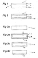
- FIG. 1 shows an example of the structure of a solar cell produced by a method according to an embodiment of the invention.
- a solar cell 10 comprises a n-type Silicon substrate 11 having a Boron-diffused layer 12 at one side and a Phosphorus-diffused layer 13 at the other side. It is noted that a practical solar cell structure also has metal contacts and an anti-reflection coating, but those components are not shown in the Figures.
- Figure 2 shows another example in which a substrate 21 of p-type Silicon is processed so as to produce a Phosphorus-diffused layer 22 at one side and a Boron-diffused layer 23 at the other side.
- the solar cell of Figure 1 is the preferred embodiment because its device performance is better than the one of Figure 2 . In the description below, embodiments of the manufacturing method of the solar cell shown in Figure 1 (i.e. n-type substrate) are discussed.
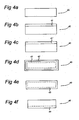
- the first step of this method is making a P-diffused layer at one side of the substrate.
- a substrate 30 is heated at 800 ⁇ 900° C for 5 ⁇ 50 minutes in an atmosphere including a O 2 and P 2 O 5 vapor.
- all surfaces of the substrate 30 are covered with a SiO 2 film 31 comprising P 2 O 5 (hereafter, SiO 2 :P 2 O 5 ).
- This SiO 2 grows from Si of the substrate 30 and oxygen, and P 2 O 5 is incorporated into the SiO 2 film 31.
- the SiO 2 :P 2 O 5 film 31 is removed by dipping the substrate 30 in a 1 ⁇ 50% HF solution for about 0.5 ⁇ 10 minutes, or exposing the substrate 30 to a HF vapor, or etching it using reactive ion etching, see Figure 3C .
- the P-diffused layer 32 is etched out, except for one side, using a mixed solution of 1 ⁇ 30% HF and 0.1 ⁇ 50% HNO 3 , or etching it using reactive ion etching.
- One side etching is possible by sealing the other side of the substrate 30 with an etch-block coating or by just floating the substrate 30 on the solution.
- the substrate 30 now comprises a P-diffused layer 32' at one side, see Figure 3D .
- FIG. 4A-4F An alternative method for manufacturing a P-diffused layer at one side of a substrate is explained with reference to Figure 4A-4F .
- one side of the surface of a substrate 40 is coated with either of liquid, paste, or gel 41 which includes P 2 O 5 and SiO 2 fine particles by either of spin-coating, spray-coating, or printing, see Figure 4B .
- the other sides of the substrate could be coated as well, but this does not influence the end result of this manufacturing method.
- the coating 41 is heated at 250 ⁇ 500 °C. The solvent evaporates or burns out when it includes organic matter.
- the P 2 O 5 and SiO 2 remain in the coating, see Figure 4C showing a coating 41'.
- the substrate 40 is heated at 800 ⁇ 900° C for 2 ⁇ 50 minutes.
- SiO 2 :P 2 O 5 see Figure 4D .
- the P diffuses into the Si core just like in Figure 3B , and a SiO 2 :P 2 O 5 film 42 and a P-diffused layer 43 are formed at all the surfaces of silicon substrate 40.
- the SiO 2 :P 2 O 5 film 42 is removed using a 1 ⁇ 50% HF solution or some other known method.
- the P-diffused layer is etched out, except the side firstly coated, using mixed solution of 1 ⁇ 0% HF and 0.1 ⁇ 50% HNO 3 , or reactive ion etching.
- One side etching is possible by sealing the other side with etch-block coating or just floating the substrate on the solution.
- Figure 4F depicts the substrate 40 having a P-diffused layer 44 at one side.
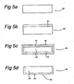
- a possible third method for manufacturing the P-diffused layer at one side of the substrate is explained with reference to Figure 5A-5D .
- First one side of a substrate 50 is blocked using a diffusion blocking layer on one side, see blocking layer 51.
- the blocking layer 51 can be formed using different processes listed below:
- P is diffused into a Si core 54 using the method as described with reference to Figure 3B or 4D .
- a SiO 2 :P 2 O 5 layer 52 is formed and P diffuses in, but the blocking layer 51 prevents the P form diffusing into the Si core 54 at one side, see Figure 5C .
- the SiO 2 :P 2 O 5 layer 52 and the blocking layer 51 are removed by dipping the substrate 50 in a 1% ⁇ 50% HF solution.
- the diffusion of P on just one side of the substrate is achieved using a back-to-back diffusion method in which two substrates are contacting each other at their surface. After the pre-diffusion of Phosphorus into the first side of the substrate, which was described above, that same first side of the substrate is blocked before the substrate is put in an oven for further processing.
- the first side 61 of the substrate 60 is blocked by a first side 62 of another substrate 63. That other substrate may be a similarly processed substrate, see Figure 6A .
- This way of blocking is referred to as back-to-back.
- One of the advantages of a back-to-back configuration is that less space is required in the oven as compared to blocking each substrate individually.
- Figure 6 B shows an alternative in which the substrate 60 is blocked by a substrate 65 that is not processed yet (i.e. a fresh substrate).
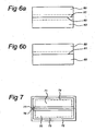
- the second side of the substrate is exposed to a Boron diffusion source.
- This Boron diffusion source may be a vapour source or a coating source.
- the substrate is heated for a certain period of time and to a certain temperature so as to diffuse Boron into the second side of the substrate and to simultaneously diffuse the Phosphorus further into said substrate (i.e. deeper than said initial depth).
- Successful results have been achieved with a Boron vapor source for the diffusion.
- Two substrates 70, 71 are put back-to-back into the oven and heated at 900 ⁇ 1000 °C for 30 ⁇ 120 minutes in an atmosphere including an O 2 and B 2 O 3 vapor, which may produced by leading N 2 through BBr 3 liquid.
- a SiO 2 film 72 which includes B 2 O 3 (hereafter, SiO 2 :B 2 O 3 ).
- B diffuses into Si until the depth of 0.01 ⁇ 1.0 ⁇ m to render B-diffused layers 73, 74.
- Part of the B 2 O 3 may sneak into the slight gap between the substrates 70, 71, but the impact is very small because of the existence of heavily diffused P at those areas.
- the P present in the P-diffused layers 76, 77 also diffuses further into the respective Si cores 70, 71 driven by the heat used. This will result in P-diffused layers that are deeper than their original depth.
- FIG. 8 shows a graph of solar cell efficiencies values fabricated on n-type multi crystalline substrates using the new method (as presented here) and the state-of-the-art method (see for example T.Buck et al., Proceedings of 21 st European Photovoltaic Solar energy Conference (4-8 September 2006, Dresden, Germany) p.1264-1267 ).
- Phosphorous is diffused-in deeper than when Phosphorous is diffused-in individually (not in a simultaneous diffusion with Boron).
- a Phosphorous concentration in the substrate at 0.5 ⁇ m depth can be more that 100 times higher than that at 5 ⁇ m depth.
- Phosphorous may also diffuse into the Silicon on the Boron-side because a small amount of Phosphorous will effuse from the Phosphorous-side to the opposite side (i.e. the Boron-diffused side).
- the amount of the Phosphorous diffused-in is smaller than that of the Boron diffused-in, and the diffused layer can easily satisfy the proper conditions for a p-type emitter.
- the amount of the Phosphorous diffused-in is still larger than the background doping of the substrate.
- the Phosphorous concentration at 0.2 ⁇ m deep may be more than 100 times higher than that at 5 ⁇ m deep.
- the invention enables the manufacturing of a Boron doping profile which satisfies the required conditions for an emitter, without allowing Phosphorous of larger quantity than Boron to diffuse into the Boron-diffused side and without allowing Boron of larger quantity than Phosphorous to diffuse into the Phosphorous-diffused side.
Landscapes
- Photovoltaic Devices (AREA)
Claims (16)
- Verfahren zur Herstellung einer Solarzelle aus kristallinem Silicium, nacheinander umfassend:- Bereitstellen eines Substrats aus kristallinem Silicium mit einer ersten Seite und einer der ersten Seite gegenüberliegenden zweiten Seite;- Vordiffundieren von Phosphor in die erste Seite des Substrats, wodurch ein SiO2 und P2O5 umfassender Film und eine mit Phosphor diffundierte Schicht mit einer anfänglichen Tiefe gebildet werden, umfassend den Schritt des:- Erwärmens des Substrats in einer O2 und P2O5 einschließenden Atmosphäre derart, dass der SiO2 und P2O5 umfassende Film und eine mit Phosphor diffundierte Zwischenschicht auf allen Seiten des Substrats hergestellt werden;- Entfernens des SiO2:P2O5-Films von allen Seiten des Substrats;- Ausätzens der mit Phosphor diffundierten Schicht mit Ausnahme auf der ersten Seite;- Blockieren der ersten Seite des Substrats;- Aussetzen der zweiten Seite des Substrats einer Bordiffusionsquelle;- Erwärmen des Substrats für eine bestimmte Zeitdauer und auf eine bestimmte Temperatur derart, dass Bor in die zweite Seite des Substrats und gleichzeitig der Phosphor weiter in das Substrat diffundiert.
- Verfahren zur Herstellung einer Solarzelle aus kristallinem Silicium, nacheinander umfassend:- Bereitstellen eines Substrats aus kristallinem Silicium mit einer ersten Seite und einer der ersten Seite gegenüberliegenden zweiten Seite;- Vordiffundieren von Phosphor in die erste Seite des Substrats, wodurch ein SiO2 und P2O5 umfassender Film und eine mit Phosphor diffundierte Schicht mit einer anfänglichen Tiefe gebildet werden, umfassend den Schritt des:- Bildens einer Beschichtung auf der ersten Seite unter Verwendung eines Siebdruckverfahrens, eines einseitigen Aufschleuderverfahrens oder eines einseitigen Aufsprühverfahrens, wobei die Beschichtung P2O5 und SiO2 umfasst;- Erwärmens des Substrats derart, dass der SiO2 und P2O5 umfassende Film und eine mit Phosphor diffundierte Zwischenschicht auf allen Seiten des Substrats hergestellt werden;- Entfernens des SiO2:P2O5-Films von allen Seiten des Substrats;- Ausätzens der mit Phosphor diffundierten Schicht mit Ausnahme auf der ersten Seite;- Blockieren der ersten Seite des Substrats;- Aussetzen der zweiten Seite des Substrats einer Bordiffusionsquelle;- Erwärmen des Substrats für eine bestimmte Zeitdauer und auf eine bestimmte Temperatur derart, dass Bor in die zweite Seite des Substrats und gleichzeitig der Phosphor weiter in das Substrat diffundiert.
- Verfahren zur Herstellung einer Solarzelle aus kristallinem Silicium, nacheinander umfassend:- Bereitstellen eines Substrats aus kristallinem Silicium mit einer ersten Seite und einer der ersten Seite gegenüberliegenden zweiten Seite;- Vordiffundieren von Phosphor in die erste Seite des Substrats, wodurch ein SiO2 und P2O5 umfassender Film und eine mit Phosphor diffundierte Schicht mit einer anfänglichen Tiefe gebildet werden, umfassend den Schritt des:- Blockierens der zweiten Seite des Substrats;- Erwärmens des Substrats in einer O2 und P2O5 einschließenden Atmosphäre derart, dass der SiO2 und P2O5 umfassende Film und eine mit Phosphor diffundierte Zwischenschicht auf allen Seiten des Substrats hergestellt werden;- Entfernen des SiO2:P2O5-Films von allen Seiten des Substrats;- Blockieren der ersten Seite des Substrats;- Aussetzen der zweiten Seite des Substrats einer Bordiffusionsquelle;- Erwärmen des Substrats für eine bestimmte Zeitdauer und auf eine bestimmte Temperatur derart, dass Bor in die zweite Seite des Substrats und gleichzeitig der Phosphor weiter in das Substrat diffundiert.
- Verfahren zur Herstellung einer Solarzelle aus kristallinem Silicium, nacheinander umfassend:- Bereitstellen eines Substrats aus kristallinem Silicium mit einer ersten Seite und einer der ersten Seite gegenüberliegenden zweiten Seite;- Vordiffundieren von Phosphor in die erste Seite des Substrats, wodurch ein SiO2 und P2O5 umfassender Film und eine mit Phosphor diffundierte Schicht mit einer anfänglichen Tiefe gebildet werden, umfassend den Schritt des:- Blockierens der zweiten Seite des Substrats;- Bildens einer Beschichtung auf der ersten Seite unter Verwendung eines Siebdruckverfahrens, eines einseitigen Aufschleuderverfahrens oder eines einseitigen Aufsprühverfahrens, wobei die Beschichtung P2O5 und SiO2 umfasst;- Erwärmens des Substrats derart, dass der SiO2 und P2O5 umfassende Film und eine mit Phosphor diffundierte Zwischenschicht auf allen Seiten des Substrats hergestellt werden;- Entfernen des SiO2:P2O5-Films von allen Seiten des Substrats;- Blockieren der ersten Seite des Substrats;- Aussetzen der zweiten Seite des Substrats einer Bordiffusionsquelle;- Erwärmen des Substrats für eine bestimmte Zeitdauer und auf eine bestimmte Temperatur derart, dass Bor in die zweite Seite des Substrats und gleichzeitig der Phosphor weiter in das Substrat diffundiert.
- Verfahren nach irgendeinem der Ansprüche 1-4, wobei das Erwärmen des Substrats bei einer Temperatur von 800~900°C erfolgt.
- Verfahren nach den Ansprüchen 3 oder 4, wobei die zweite Seite des Substrats mittels Bilden einer diffusionsblockierenden Schicht auf der zweiten Seite blockiert wird.
- Verfahren nach den Ansprüchen 3 oder 4, wobei die zweite Seite des Substrats durch ein anderes Substrat blockiert wird.
- Verfahren nach irgendeinem der vorangehenden Ansprüche, wobei die erste Seite des Substrats durch eine erste Seite eines anderen Substrats blockiert wird.
- Verfahren nach Anspruch 8, wobei das andere Substrat ein bearbeitetes Substrat umfasst, das zum Zeitpunkt des Blockierens in ähnlicher Weise wie das Substrat bearbeitet ist.
- Verfahren nach irgendeinem der Ansprüche 1-4 oder 6-7, wobei die erste Seite des Substrats mittels Bedecken der ersten Seite des Substrats mit einer Beschichtungsschicht blockiert wird.
- Verfahren nach irgendeinem der vorangehenden Ansprüche, wobei das Aussetzen der zweiten Seite des Substrats einer Bordiffusionsquelle das Aussetzen des Substrats einer O2 und B2O3 einschließenden Atmosphäre umfasst.
- Verfahren nach Anspruch 11, wobei die bestimmte Zeitdauer zwischen 30-120 Minuten liegt.
- Verfahren nach Anspruch 11 oder 12, wobei die bestimmte Temperatur zwischen 900-1000°C liegt.
- Verfahren nach Anspruch 11 oder 12, wobei das B2O3 durch Leiten von N2 durch eine BBr3-Flüssigkeit hergestellt wird.
- Solarzelle, hergestellt durch ein Verfahren nach irgendeinem der vorangehenden Ansprüche, dadurch gekennzeichnet, dass eine Phosphorkonzentration bei einer Tiefe von 0,5 µm der ersten Seite in dem Substrat um mehr als das 100-fache höher ist, als die Phosphorkonzentration bei einer Tiefe von 5 µm der Seite.
- Solarzelle nach Anspruch 15, wobei die Phosphorkonzentration bei einer Tiefe von 0,2 µm der zweiten Seite in dem Substrat um mehr als das 100-fache höher ist, als die Phosphorkonzentration bei einer Tiefe von 5 µm der Seite.
Applications Claiming Priority (2)
| Application Number | Priority Date | Filing Date | Title |
|---|---|---|---|
| NL2000999A NL2000999C2 (nl) | 2007-11-13 | 2007-11-13 | Werkwijze voor het fabriceren van kristallijn silicium zonnecellen met gebruikmaking van co-diffusie van boor en fosfor. |
| PCT/NL2008/050724 WO2009064183A1 (en) | 2007-11-13 | 2008-11-13 | Method of manufacturing crystalline silicon solar cells using co diffusion of boron and phosphorus |
Publications (3)
| Publication Number | Publication Date |
|---|---|
| EP2210283A1 EP2210283A1 (de) | 2010-07-28 |
| EP2210283B1 EP2210283B1 (de) | 2011-10-19 |
| EP2210283B2 true EP2210283B2 (de) | 2015-07-15 |
Family
ID=39473196
Family Applications (1)
| Application Number | Title | Priority Date | Filing Date |
|---|---|---|---|
| EP08849334.1A Active EP2210283B2 (de) | 2007-11-13 | 2008-11-13 | Verfahren zur herstellung von solarzellen aus kristallinem silicium anhand der gemeinsamen diffusion von bor und phosphor |
Country Status (10)
| Country | Link |
|---|---|
| US (1) | US8445312B2 (de) |
| EP (1) | EP2210283B2 (de) |
| JP (1) | JP2011503896A (de) |
| KR (1) | KR101515255B1 (de) |
| CN (1) | CN101919070B (de) |
| AT (1) | ATE529897T1 (de) |
| AU (1) | AU2008321599A1 (de) |
| ES (1) | ES2375324T3 (de) |
| NL (1) | NL2000999C2 (de) |
| WO (1) | WO2009064183A1 (de) |
Families Citing this family (27)
| Publication number | Priority date | Publication date | Assignee | Title |
|---|---|---|---|---|
| US8518170B2 (en) | 2008-12-29 | 2013-08-27 | Honeywell International Inc. | Boron-comprising inks for forming boron-doped regions in semiconductor substrates using non-contact printing processes and methods for fabricating such boron-comprising inks |
| KR101119916B1 (ko) * | 2009-08-24 | 2012-03-13 | 삼성전자주식회사 | 그래핀 전극과 유기물/무기물 복합소재를 사용한 전자 소자 및 그 제조 방법 |
| JP4868079B1 (ja) * | 2010-01-25 | 2012-02-01 | 日立化成工業株式会社 | n型拡散層形成組成物、n型拡散層の製造方法、及び太陽電池セルの製造方法 |
| US20130089944A1 (en) * | 2010-06-11 | 2013-04-11 | Amtech Systems, Inc. | Solar cell silicon wafer process |
| US20120122265A1 (en) * | 2010-11-17 | 2012-05-17 | Hitachi Chemical Company, Ltd. | Method for producing photovoltaic cell |
| WO2012108766A2 (en) | 2011-02-08 | 2012-08-16 | Tsc Solar B.V. | A method of manufactering a solar cell and a solar cell |
| CN102191562B (zh) * | 2011-04-25 | 2012-08-29 | 苏州阿特斯阳光电力科技有限公司 | 一种n型晶体硅太阳电池的硼扩散方法 |
| CN102263159A (zh) * | 2011-05-31 | 2011-11-30 | 江阴鑫辉太阳能有限公司 | 一种利用硼磷共扩散制备n型太阳电池的工艺 |
| CN105489662A (zh) * | 2011-07-19 | 2016-04-13 | 日立化成株式会社 | n型扩散层形成用组合物、n型扩散层的制造方法以及太阳能电池元件的制造方法 |
| JPWO2013015173A1 (ja) * | 2011-07-25 | 2015-02-23 | 日立化成株式会社 | 太陽電池基板、太陽電池基板の製造方法、太陽電池素子及び太陽電池 |
| US8629294B2 (en) | 2011-08-25 | 2014-01-14 | Honeywell International Inc. | Borate esters, boron-comprising dopants, and methods of fabricating boron-comprising dopants |
| US8975170B2 (en) | 2011-10-24 | 2015-03-10 | Honeywell International Inc. | Dopant ink compositions for forming doped regions in semiconductor substrates, and methods for fabricating dopant ink compositions |
| DE102013102574A1 (de) | 2012-03-13 | 2013-09-19 | centrotherm cell & module GmbH | Verfahren zur Herstellung einer Rückkontaktsolarzelle |
| DE102013102573A1 (de) | 2012-03-13 | 2013-09-19 | centrotherm cell & module GmbH | Verfahren zur Herstellung einer Solarzelle |
| US9224906B2 (en) | 2012-03-20 | 2015-12-29 | Tempress Ip B.V. | Method for manufacturing a solar cell |
| CN102683492B (zh) * | 2012-05-27 | 2014-10-15 | 苏州阿特斯阳光电力科技有限公司 | 双面背接触晶体硅太阳能电池的制备方法 |
| CN102797040B (zh) * | 2012-08-22 | 2015-08-12 | 中国科学院电工研究所 | 一种硼(b)扩散掺杂的方法 |
| US8722545B2 (en) * | 2012-08-27 | 2014-05-13 | Stmicroelectronics Pte Ltd. | Method of selectively deglazing P205 |
| JP6114108B2 (ja) * | 2013-05-20 | 2017-04-12 | 信越化学工業株式会社 | 太陽電池の製造方法 |
| KR20150007394A (ko) * | 2013-07-10 | 2015-01-21 | 현대중공업 주식회사 | 양면수광형 태양전지의 제조방법 |
| CN104157740B (zh) * | 2014-09-03 | 2017-02-08 | 苏州阿特斯阳光电力科技有限公司 | 一种n型双面太阳能电池的制备方法 |
| DE102015226516B4 (de) * | 2015-12-22 | 2018-02-22 | Fraunhofer-Gesellschaft zur Förderung der angewandten Forschung eingetragener Verein | Verfahren zur Dotierung von Halbleitersubstraten mittels eines Co-Diffusionsprozesses |
| JP6356855B2 (ja) * | 2017-03-16 | 2018-07-11 | 信越化学工業株式会社 | 太陽電池の製造方法 |
| TW201903851A (zh) * | 2017-06-13 | 2019-01-16 | 日商東京應化工業股份有限公司 | 太陽電池元件用矽基板之製造方法 |
| CN109301031B (zh) * | 2018-09-12 | 2021-08-31 | 江苏林洋光伏科技有限公司 | N型双面电池的制作方法 |
| CN110085699A (zh) * | 2019-04-22 | 2019-08-02 | 通威太阳能(成都)有限公司 | 一种具有钝化接触结构的p型高效电池及其制作方法 |
| CN110233180A (zh) * | 2019-06-02 | 2019-09-13 | 苏州腾晖光伏技术有限公司 | P型背面隧穿氧化钝化接触太阳能电池的制备方法 |
Citations (6)
| Publication number | Priority date | Publication date | Assignee | Title |
|---|---|---|---|---|
| US5468652A (en) † | 1993-07-14 | 1995-11-21 | Sandia Corporation | Method of making a back contacted solar cell |
| US5665175A (en) † | 1990-05-30 | 1997-09-09 | Safir; Yakov | Bifacial solar cell |
| EP0999598A1 (de) † | 1998-11-04 | 2000-05-10 | Shin-Etsu Chemical Co., Ltd. | Solarzelle und Verfahren zur Herstellung einer Solarzelle |
| US20010050404A1 (en) † | 2000-06-02 | 2001-12-13 | Honda Giken Kogyo Kabushiki Kaisha | Solar cell and method of manufacturing the same |
| US20050133084A1 (en) † | 2003-10-10 | 2005-06-23 | Toshio Joge | Silicon solar cell and production method thereof |
| EP1575087A2 (de) † | 2000-11-29 | 2005-09-14 | Origin Energy Solar Pty.Ltd | Halbleiter-wafer-verarbeitung zur Vergrösserung des benutzbaren planaren Oberflächeninhalts |
Family Cites Families (20)
| Publication number | Priority date | Publication date | Assignee | Title |
|---|---|---|---|---|
| US4451969A (en) * | 1983-01-10 | 1984-06-05 | Mobil Solar Energy Corporation | Method of fabricating solar cells |
| US4557037A (en) * | 1984-10-31 | 1985-12-10 | Mobil Solar Energy Corporation | Method of fabricating solar cells |
| US5082791A (en) * | 1988-05-13 | 1992-01-21 | Mobil Solar Energy Corporation | Method of fabricating solar cells |
| US5792280A (en) * | 1994-05-09 | 1998-08-11 | Sandia Corporation | Method for fabricating silicon cells |
| JP4812147B2 (ja) * | 1999-09-07 | 2011-11-09 | 株式会社日立製作所 | 太陽電池の製造方法 |
| DE10021440A1 (de) * | 2000-05-03 | 2001-11-15 | Univ Konstanz | Verfahren zur Herstellung einer Solarzelle und nach diesem Verfahren hergestellte Solarzelle |
| US7435361B2 (en) * | 2005-04-14 | 2008-10-14 | E.I. Du Pont De Nemours And Company | Conductive compositions and processes for use in the manufacture of semiconductor devices |
| JP4657068B2 (ja) * | 2005-09-22 | 2011-03-23 | シャープ株式会社 | 裏面接合型太陽電池の製造方法 |
| US20080057220A1 (en) * | 2006-01-31 | 2008-03-06 | Robert Bachrach | Silicon photovoltaic cell junction formed from thin film doping source |
| JP2008112847A (ja) * | 2006-10-30 | 2008-05-15 | Shin Etsu Chem Co Ltd | 単結晶シリコン太陽電池の製造方法及び単結晶シリコン太陽電池 |
| EP2191479A1 (de) * | 2007-10-18 | 2010-06-02 | E. I. du Pont de Nemours and Company | Leitfähige zusammensetzungen und verfahren zu ihrer verwendung bei der herstellung von halbleiterbauelementen: flussmaterialien |
| DE102008019402A1 (de) * | 2008-04-14 | 2009-10-15 | Gebr. Schmid Gmbh & Co. | Verfahren zur selektiven Dotierung von Silizium sowie damit behandeltes Silizium-Substrat |
| US8309446B2 (en) * | 2008-07-16 | 2012-11-13 | Applied Materials, Inc. | Hybrid heterojunction solar cell fabrication using a doping layer mask |
| US7838400B2 (en) * | 2008-07-17 | 2010-11-23 | Applied Materials, Inc. | Rapid thermal oxide passivated solar cell with improved junction |
| US8231934B2 (en) * | 2008-11-26 | 2012-07-31 | E. I. Du Pont De Nemours And Company | Conductive paste for solar cell electrode |
| WO2011035268A2 (en) * | 2009-09-18 | 2011-03-24 | Applied Materials, Inc. | Threshold adjustment implants for reducing surface recombination in solar cells |
| CN102612735B (zh) * | 2009-10-26 | 2015-12-16 | 新南创新私人有限公司 | 用于硅太阳能电池的改善的金属化方法 |
| US8586862B2 (en) * | 2009-11-18 | 2013-11-19 | Solar Wind Technologies, Inc. | Method of manufacturing photovoltaic cells, photovoltaic cells produced thereby and uses thereof |
| KR101141578B1 (ko) * | 2010-09-14 | 2012-05-17 | (주)세미머티리얼즈 | 태양전지 제조방법. |
| CN103477450A (zh) * | 2011-04-21 | 2013-12-25 | 应用材料公司 | 在太阳能电池基板中形成p-n结的方法 |
-
2007
- 2007-11-13 NL NL2000999A patent/NL2000999C2/nl not_active IP Right Cessation
-
2008
- 2008-11-13 KR KR1020107012964A patent/KR101515255B1/ko not_active Expired - Fee Related
- 2008-11-13 ES ES08849334T patent/ES2375324T3/es active Active
- 2008-11-13 JP JP2010533981A patent/JP2011503896A/ja active Pending
- 2008-11-13 US US12/742,682 patent/US8445312B2/en active Active
- 2008-11-13 AU AU2008321599A patent/AU2008321599A1/en not_active Abandoned
- 2008-11-13 WO PCT/NL2008/050724 patent/WO2009064183A1/en not_active Ceased
- 2008-11-13 EP EP08849334.1A patent/EP2210283B2/de active Active
- 2008-11-13 AT AT08849334T patent/ATE529897T1/de not_active IP Right Cessation
- 2008-11-13 CN CN2008801241277A patent/CN101919070B/zh active Active
Patent Citations (6)
| Publication number | Priority date | Publication date | Assignee | Title |
|---|---|---|---|---|
| US5665175A (en) † | 1990-05-30 | 1997-09-09 | Safir; Yakov | Bifacial solar cell |
| US5468652A (en) † | 1993-07-14 | 1995-11-21 | Sandia Corporation | Method of making a back contacted solar cell |
| EP0999598A1 (de) † | 1998-11-04 | 2000-05-10 | Shin-Etsu Chemical Co., Ltd. | Solarzelle und Verfahren zur Herstellung einer Solarzelle |
| US20010050404A1 (en) † | 2000-06-02 | 2001-12-13 | Honda Giken Kogyo Kabushiki Kaisha | Solar cell and method of manufacturing the same |
| EP1575087A2 (de) † | 2000-11-29 | 2005-09-14 | Origin Energy Solar Pty.Ltd | Halbleiter-wafer-verarbeitung zur Vergrösserung des benutzbaren planaren Oberflächeninhalts |
| US20050133084A1 (en) † | 2003-10-10 | 2005-06-23 | Toshio Joge | Silicon solar cell and production method thereof |
Non-Patent Citations (3)
| Title |
|---|
| J. Y. LEE: "Rapid Thermal Processing of Silicon Solar Cells-Passivation and Diffusion", 2003, pages: 1 - 164 † |
| K.R. MCINTOSH: "Lumps, Humps and Bumps: Three Detrimental Effects in the Current-Voltage Curve of Silicon Solar Cells", January 2001, pages: 1 - 180 † |
| S. SIVOTHTHAMAN ET AL.: "Fabrication of large area silicon solar cells by rapid thermal processing", APPLIED PHYSICS LETTERS, vol. 67, no. 16, 16 October 1995 (1995-10-16), pages 2335 - 2337, XP000544370, DOI: doi:10.1063/1.114336 † |
Also Published As
| Publication number | Publication date |
|---|---|
| US8445312B2 (en) | 2013-05-21 |
| JP2011503896A (ja) | 2011-01-27 |
| WO2009064183A1 (en) | 2009-05-22 |
| AU2008321599A1 (en) | 2009-05-22 |
| KR101515255B1 (ko) | 2015-04-24 |
| NL2000999C2 (nl) | 2009-05-14 |
| US20100319771A1 (en) | 2010-12-23 |
| KR20100102113A (ko) | 2010-09-20 |
| CN101919070B (zh) | 2012-10-10 |
| EP2210283A1 (de) | 2010-07-28 |
| EP2210283B1 (de) | 2011-10-19 |
| ES2375324T3 (es) | 2012-02-28 |
| CN101919070A (zh) | 2010-12-15 |
| ATE529897T1 (de) | 2011-11-15 |
Similar Documents
| Publication | Publication Date | Title |
|---|---|---|
| EP2210283B2 (de) | Verfahren zur herstellung von solarzellen aus kristallinem silicium anhand der gemeinsamen diffusion von bor und phosphor | |
| JP4335668B2 (ja) | 太陽電池の製造方法 | |
| US9178086B2 (en) | Method for fabricating back-contact type solar cell | |
| KR102055472B1 (ko) | 태양 전지의 공간적으로 위치된 확산 영역을 형성하기 위한 도펀트의 이온 주입 | |
| CN101652865A (zh) | 太阳能电池的氮氧化物钝化 | |
| CN105051867B (zh) | 在基板中提供硼掺杂区域的方法以及使用该基板的太阳能电池 | |
| CN107591461B (zh) | 一种制备太阳能电池的扩散工艺 | |
| GB2077996A (en) | Method of manufacturing solar cells | |
| EP3685446B1 (de) | Dotierstoffverstärkte solarzelle und verfahren zu ihrer herstellung | |
| EP3427303A1 (de) | Solarzelle mit dotierten polysiliciumoberflächenbereichen und verfahren zur herstellung davon | |
| WO2011160819A2 (en) | Method for fabrication of a back side contact solar cell | |
| KR20160061409A (ko) | 태양 전지를 생성하는 방법 | |
| Ebong et al. | High efficiency inline diffused emitter (ILDE) solar cells on mono‐crystalline CZ silicon | |
| KR101160116B1 (ko) | 후면 접합 태양전지의 제조방법 | |
| US9330917B2 (en) | Passivation layer for workpieces formed from a polymer | |
| KR101162123B1 (ko) | 도펀트 함유된 도핑마스크를 이용한 선택적 에미터 형성방법과 태양전지 제조방법 | |
| KR100995654B1 (ko) | 태양전지 및 그 제조방법 | |
| US20170330990A1 (en) | Method for manufacturing photovoltaic device | |
| US20110036398A1 (en) | Method for manufacturing a semiconductor component | |
| US20140273330A1 (en) | Method of forming single side textured semiconductor workpieces | |
| KR101061681B1 (ko) | 태양전지 제조 방법 | |
| KR20170079766A (ko) | 양면 수광형 태양전지 및 그 제조 방법 | |
| KR20150024485A (ko) | Perl형 태양전지의 제조방법 | |
| TW201019493A (en) | Method of manufacturing crystalline silicon solar cells using co diffusion of Boron and phosphorus |
Legal Events
| Date | Code | Title | Description |
|---|---|---|---|
| PUAI | Public reference made under article 153(3) epc to a published international application that has entered the european phase |
Free format text: ORIGINAL CODE: 0009012 |
|
| 17P | Request for examination filed |
Effective date: 20100512 |
|
| AK | Designated contracting states |
Kind code of ref document: A1 Designated state(s): AT BE BG CH CY CZ DE DK EE ES FI FR GB GR HR HU IE IS IT LI LT LU LV MC MT NL NO PL PT RO SE SI SK TR |
|
| AX | Request for extension of the european patent |
Extension state: AL BA MK RS |
|
| DAX | Request for extension of the european patent (deleted) | ||
| GRAP | Despatch of communication of intention to grant a patent |
Free format text: ORIGINAL CODE: EPIDOSNIGR1 |
|
| GRAS | Grant fee paid |
Free format text: ORIGINAL CODE: EPIDOSNIGR3 |
|
| GRAA | (expected) grant |
Free format text: ORIGINAL CODE: 0009210 |
|
| AK | Designated contracting states |
Kind code of ref document: B1 Designated state(s): AT BE BG CH CY CZ DE DK EE ES FI FR GB GR HR HU IE IS IT LI LT LU LV MC MT NL NO PL PT RO SE SI SK TR |
|
| REG | Reference to a national code |
Ref country code: GB Ref legal event code: FG4D |
|
| REG | Reference to a national code |
Ref country code: CH Ref legal event code: EP |
|
| REG | Reference to a national code |
Ref country code: IE Ref legal event code: FG4D |
|
| REG | Reference to a national code |
Ref country code: DE Ref legal event code: R096 Ref document number: 602008010665 Country of ref document: DE Effective date: 20120112 |
|
| REG | Reference to a national code |
Ref country code: NL Ref legal event code: T3 |
|
| PGFP | Annual fee paid to national office [announced via postgrant information from national office to epo] |
Ref country code: FR Payment date: 20111214 Year of fee payment: 4 Ref country code: ES Payment date: 20111228 Year of fee payment: 4 |
|
| REG | Reference to a national code |
Ref country code: ES Ref legal event code: FG2A Ref document number: 2375324 Country of ref document: ES Kind code of ref document: T3 Effective date: 20120228 |
|
| LTIE | Lt: invalidation of european patent or patent extension |
Effective date: 20111019 |
|
| REG | Reference to a national code |
Ref country code: AT Ref legal event code: MK05 Ref document number: 529897 Country of ref document: AT Kind code of ref document: T Effective date: 20111019 |
|
| PG25 | Lapsed in a contracting state [announced via postgrant information from national office to epo] |
Ref country code: IS Free format text: LAPSE BECAUSE OF FAILURE TO SUBMIT A TRANSLATION OF THE DESCRIPTION OR TO PAY THE FEE WITHIN THE PRESCRIBED TIME-LIMIT Effective date: 20120219 Ref country code: NO Free format text: LAPSE BECAUSE OF FAILURE TO SUBMIT A TRANSLATION OF THE DESCRIPTION OR TO PAY THE FEE WITHIN THE PRESCRIBED TIME-LIMIT Effective date: 20120119 Ref country code: BE Free format text: LAPSE BECAUSE OF FAILURE TO SUBMIT A TRANSLATION OF THE DESCRIPTION OR TO PAY THE FEE WITHIN THE PRESCRIBED TIME-LIMIT Effective date: 20111019 Ref country code: LT Free format text: LAPSE BECAUSE OF FAILURE TO SUBMIT A TRANSLATION OF THE DESCRIPTION OR TO PAY THE FEE WITHIN THE PRESCRIBED TIME-LIMIT Effective date: 20111019 |
|
| PG25 | Lapsed in a contracting state [announced via postgrant information from national office to epo] |
Ref country code: LV Free format text: LAPSE BECAUSE OF FAILURE TO SUBMIT A TRANSLATION OF THE DESCRIPTION OR TO PAY THE FEE WITHIN THE PRESCRIBED TIME-LIMIT Effective date: 20111019 Ref country code: PT Free format text: LAPSE BECAUSE OF FAILURE TO SUBMIT A TRANSLATION OF THE DESCRIPTION OR TO PAY THE FEE WITHIN THE PRESCRIBED TIME-LIMIT Effective date: 20120220 Ref country code: SI Free format text: LAPSE BECAUSE OF FAILURE TO SUBMIT A TRANSLATION OF THE DESCRIPTION OR TO PAY THE FEE WITHIN THE PRESCRIBED TIME-LIMIT Effective date: 20111019 Ref country code: SE Free format text: LAPSE BECAUSE OF FAILURE TO SUBMIT A TRANSLATION OF THE DESCRIPTION OR TO PAY THE FEE WITHIN THE PRESCRIBED TIME-LIMIT Effective date: 20111019 Ref country code: HR Free format text: LAPSE BECAUSE OF FAILURE TO SUBMIT A TRANSLATION OF THE DESCRIPTION OR TO PAY THE FEE WITHIN THE PRESCRIBED TIME-LIMIT Effective date: 20111019 Ref country code: GR Free format text: LAPSE BECAUSE OF FAILURE TO SUBMIT A TRANSLATION OF THE DESCRIPTION OR TO PAY THE FEE WITHIN THE PRESCRIBED TIME-LIMIT Effective date: 20120120 |
|
| PG25 | Lapsed in a contracting state [announced via postgrant information from national office to epo] |
Ref country code: MC Free format text: LAPSE BECAUSE OF NON-PAYMENT OF DUE FEES Effective date: 20111130 Ref country code: CY Free format text: LAPSE BECAUSE OF FAILURE TO SUBMIT A TRANSLATION OF THE DESCRIPTION OR TO PAY THE FEE WITHIN THE PRESCRIBED TIME-LIMIT Effective date: 20111019 |
|
| PLBI | Opposition filed |
Free format text: ORIGINAL CODE: 0009260 |
|
| PG25 | Lapsed in a contracting state [announced via postgrant information from national office to epo] |
Ref country code: CZ Free format text: LAPSE BECAUSE OF FAILURE TO SUBMIT A TRANSLATION OF THE DESCRIPTION OR TO PAY THE FEE WITHIN THE PRESCRIBED TIME-LIMIT Effective date: 20111019 Ref country code: BG Free format text: LAPSE BECAUSE OF FAILURE TO SUBMIT A TRANSLATION OF THE DESCRIPTION OR TO PAY THE FEE WITHIN THE PRESCRIBED TIME-LIMIT Effective date: 20120119 Ref country code: EE Free format text: LAPSE BECAUSE OF FAILURE TO SUBMIT A TRANSLATION OF THE DESCRIPTION OR TO PAY THE FEE WITHIN THE PRESCRIBED TIME-LIMIT Effective date: 20111019 Ref country code: SK Free format text: LAPSE BECAUSE OF FAILURE TO SUBMIT A TRANSLATION OF THE DESCRIPTION OR TO PAY THE FEE WITHIN THE PRESCRIBED TIME-LIMIT Effective date: 20111019 Ref country code: DK Free format text: LAPSE BECAUSE OF FAILURE TO SUBMIT A TRANSLATION OF THE DESCRIPTION OR TO PAY THE FEE WITHIN THE PRESCRIBED TIME-LIMIT Effective date: 20111019 |
|
| 26 | Opposition filed |
Opponent name: Q-CELLS SE Effective date: 20120718 |
|
| PLAX | Notice of opposition and request to file observation + time limit sent |
Free format text: ORIGINAL CODE: EPIDOSNOBS2 |
|
| REG | Reference to a national code |
Ref country code: IE Ref legal event code: MM4A |
|
| PG25 | Lapsed in a contracting state [announced via postgrant information from national office to epo] |
Ref country code: PL Free format text: LAPSE BECAUSE OF FAILURE TO SUBMIT A TRANSLATION OF THE DESCRIPTION OR TO PAY THE FEE WITHIN THE PRESCRIBED TIME-LIMIT Effective date: 20111019 Ref country code: RO Free format text: LAPSE BECAUSE OF FAILURE TO SUBMIT A TRANSLATION OF THE DESCRIPTION OR TO PAY THE FEE WITHIN THE PRESCRIBED TIME-LIMIT Effective date: 20111019 |
|
| REG | Reference to a national code |
Ref country code: DE Ref legal event code: R026 Ref document number: 602008010665 Country of ref document: DE Effective date: 20120718 |
|
| PG25 | Lapsed in a contracting state [announced via postgrant information from national office to epo] |
Ref country code: IE Free format text: LAPSE BECAUSE OF NON-PAYMENT OF DUE FEES Effective date: 20111113 |
|
| PLAF | Information modified related to communication of a notice of opposition and request to file observations + time limit |
Free format text: ORIGINAL CODE: EPIDOSCOBS2 |
|
| PG25 | Lapsed in a contracting state [announced via postgrant information from national office to epo] |
Ref country code: AT Free format text: LAPSE BECAUSE OF FAILURE TO SUBMIT A TRANSLATION OF THE DESCRIPTION OR TO PAY THE FEE WITHIN THE PRESCRIBED TIME-LIMIT Effective date: 20111019 |
|
| PG25 | Lapsed in a contracting state [announced via postgrant information from national office to epo] |
Ref country code: MT Free format text: LAPSE BECAUSE OF FAILURE TO SUBMIT A TRANSLATION OF THE DESCRIPTION OR TO PAY THE FEE WITHIN THE PRESCRIBED TIME-LIMIT Effective date: 20111019 |
|
| PLBB | Reply of patent proprietor to notice(s) of opposition received |
Free format text: ORIGINAL CODE: EPIDOSNOBS3 |
|
| PG25 | Lapsed in a contracting state [announced via postgrant information from national office to epo] |
Ref country code: LU Free format text: LAPSE BECAUSE OF NON-PAYMENT OF DUE FEES Effective date: 20111113 |
|
| PG25 | Lapsed in a contracting state [announced via postgrant information from national office to epo] |
Ref country code: FI Free format text: LAPSE BECAUSE OF FAILURE TO SUBMIT A TRANSLATION OF THE DESCRIPTION OR TO PAY THE FEE WITHIN THE PRESCRIBED TIME-LIMIT Effective date: 20111019 |
|
| REG | Reference to a national code |
Ref country code: CH Ref legal event code: PL |
|
| GBPC | Gb: european patent ceased through non-payment of renewal fee |
Effective date: 20121113 |
|
| PG25 | Lapsed in a contracting state [announced via postgrant information from national office to epo] |
Ref country code: CH Free format text: LAPSE BECAUSE OF NON-PAYMENT OF DUE FEES Effective date: 20121130 Ref country code: LI Free format text: LAPSE BECAUSE OF NON-PAYMENT OF DUE FEES Effective date: 20121130 |
|
| REG | Reference to a national code |
Ref country code: FR Ref legal event code: ST Effective date: 20130731 |
|
| PG25 | Lapsed in a contracting state [announced via postgrant information from national office to epo] |
Ref country code: IT Free format text: LAPSE BECAUSE OF NON-PAYMENT OF DUE FEES Effective date: 20121113 |
|
| PG25 | Lapsed in a contracting state [announced via postgrant information from national office to epo] |
Ref country code: TR Free format text: LAPSE BECAUSE OF NON-PAYMENT OF DUE FEES Effective date: 20121112 Ref country code: HU Free format text: LAPSE BECAUSE OF FAILURE TO SUBMIT A TRANSLATION OF THE DESCRIPTION OR TO PAY THE FEE WITHIN THE PRESCRIBED TIME-LIMIT Effective date: 20111019 |
|
| PG25 | Lapsed in a contracting state [announced via postgrant information from national office to epo] |
Ref country code: GB Free format text: LAPSE BECAUSE OF NON-PAYMENT OF DUE FEES Effective date: 20121113 Ref country code: FR Free format text: LAPSE BECAUSE OF NON-PAYMENT OF DUE FEES Effective date: 20121130 |
|
| REG | Reference to a national code |
Ref country code: ES Ref legal event code: FD2A Effective date: 20140304 |
|
| PG25 | Lapsed in a contracting state [announced via postgrant information from national office to epo] |
Ref country code: ES Free format text: LAPSE BECAUSE OF NON-PAYMENT OF DUE FEES Effective date: 20121114 |
|
| REG | Reference to a national code |
Ref country code: NL Ref legal event code: PLED Effective date: 20150116 |
|
| PUAH | Patent maintained in amended form |
Free format text: ORIGINAL CODE: 0009272 |
|
| STAA | Information on the status of an ep patent application or granted ep patent |
Free format text: STATUS: PATENT MAINTAINED AS AMENDED |
|
| 27A | Patent maintained in amended form |
Effective date: 20150715 |
|
| AK | Designated contracting states |
Kind code of ref document: B2 Designated state(s): AT BE BG CH CY CZ DE DK EE ES FI FR GB GR HR HU IE IS IT LI LT LU LV MC MT NL NO PL PT RO SE SI SK TR |
|
| REG | Reference to a national code |
Ref country code: DE Ref legal event code: R102 Ref document number: 602008010665 Country of ref document: DE |
|
| REG | Reference to a national code |
Ref country code: NL Ref legal event code: T3 |
|
| REG | Reference to a national code |
Ref country code: NL Ref legal event code: RF Free format text: RIGHT OF PLEDGE, REMOVED Effective date: 20180413 |
|
| REG | Reference to a national code |
Ref country code: NL Ref legal event code: PD Owner name: NEDERLANDSE ORGANISATIE VOOR TOEGEPAST-NATUURWETEN Free format text: DETAILS ASSIGNMENT: CHANGE OF OWNER(S), ASSIGNMENT; FORMER OWNER NAME: STICHTING ENERGIEONDERZOEK CENTRUM NEDERLAND Effective date: 20190220 |
|
| P01 | Opt-out of the competence of the unified patent court (upc) registered |
Effective date: 20230522 |
|
| REG | Reference to a national code |
Ref country code: DE Ref legal event code: R079 Ref document number: 602008010665 Country of ref document: DE Free format text: PREVIOUS MAIN CLASS: H01L0031180000 Ipc: H10F0071000000 |
|
| REG | Reference to a national code |
Ref country code: DE Ref legal event code: R081 Ref document number: 602008010665 Country of ref document: DE Owner name: NEDERLANDSE ORGANISATIE VOOR TOEGEPASTNATUURWE, NL Free format text: FORMER OWNER: STICHTING ENERGIEONDERZOEK CENTRUM NEDERLAND, PETTEN, NL |
|
| PGFP | Annual fee paid to national office [announced via postgrant information from national office to epo] |
Ref country code: NL Payment date: 20251119 Year of fee payment: 18 |
|
| PGFP | Annual fee paid to national office [announced via postgrant information from national office to epo] |
Ref country code: DE Payment date: 20251119 Year of fee payment: 18 |