EP2210283B2 - Method of manufacturing crystalline silicon solar cells using co diffusion of boron and phosphorus - Google Patents
Method of manufacturing crystalline silicon solar cells using co diffusion of boron and phosphorus Download PDFInfo
- Publication number
- EP2210283B2 EP2210283B2 EP08849334.1A EP08849334A EP2210283B2 EP 2210283 B2 EP2210283 B2 EP 2210283B2 EP 08849334 A EP08849334 A EP 08849334A EP 2210283 B2 EP2210283 B2 EP 2210283B2
- Authority
- EP
- European Patent Office
- Prior art keywords
- substrate
- phosphorus
- sio
- boron
- film
- Prior art date
- Legal status (The legal status is an assumption and is not a legal conclusion. Google has not performed a legal analysis and makes no representation as to the accuracy of the status listed.)
- Active
Links
- 238000009792 diffusion process Methods 0.000 title claims abstract description 48
- 229910052796 boron Inorganic materials 0.000 title claims abstract description 44
- ZOXJGFHDIHLPTG-UHFFFAOYSA-N Boron Chemical compound [B] ZOXJGFHDIHLPTG-UHFFFAOYSA-N 0.000 title claims abstract description 43
- 229910052698 phosphorus Inorganic materials 0.000 title claims abstract description 35
- OAICVXFJPJFONN-UHFFFAOYSA-N Phosphorus Chemical compound [P] OAICVXFJPJFONN-UHFFFAOYSA-N 0.000 title claims abstract description 33
- 239000011574 phosphorus Substances 0.000 title claims abstract description 33
- 238000004519 manufacturing process Methods 0.000 title claims abstract description 18
- 229910021419 crystalline silicon Inorganic materials 0.000 title claims abstract description 13
- 239000000758 substrate Substances 0.000 claims abstract description 122
- 230000000903 blocking effect Effects 0.000 claims abstract description 17
- 238000010438 heat treatment Methods 0.000 claims abstract description 11
- VYPSYNLAJGMNEJ-UHFFFAOYSA-N Silicium dioxide Chemical compound O=[Si]=O VYPSYNLAJGMNEJ-UHFFFAOYSA-N 0.000 claims description 68
- 239000010410 layer Substances 0.000 claims description 41
- 238000000034 method Methods 0.000 claims description 40
- 229910052681 coesite Inorganic materials 0.000 claims description 34
- 229910052906 cristobalite Inorganic materials 0.000 claims description 34
- 239000000377 silicon dioxide Substances 0.000 claims description 34
- 229910052682 stishovite Inorganic materials 0.000 claims description 34
- 229910052905 tridymite Inorganic materials 0.000 claims description 34
- 239000011248 coating agent Substances 0.000 claims description 15
- 238000000576 coating method Methods 0.000 claims description 15
- ILAHWRKJUDSMFH-UHFFFAOYSA-N boron tribromide Chemical compound BrB(Br)Br ILAHWRKJUDSMFH-UHFFFAOYSA-N 0.000 claims description 6
- 238000005530 etching Methods 0.000 claims description 6
- 239000007788 liquid Substances 0.000 claims description 5
- 229910015845 BBr3 Inorganic materials 0.000 claims description 3
- 239000011247 coating layer Substances 0.000 claims 1
- BHEPBYXIRTUNPN-UHFFFAOYSA-N hydridophosphorus(.) (triplet) Chemical compound [PH] BHEPBYXIRTUNPN-UHFFFAOYSA-N 0.000 description 30
- XUIMIQQOPSSXEZ-UHFFFAOYSA-N Silicon Chemical compound [Si] XUIMIQQOPSSXEZ-UHFFFAOYSA-N 0.000 description 11
- 229910052710 silicon Inorganic materials 0.000 description 11
- 239000010703 silicon Substances 0.000 description 11
- 239000000243 solution Substances 0.000 description 6
- GWEVSGVZZGPLCZ-UHFFFAOYSA-N Titan oxide Chemical compound O=[Ti]=O GWEVSGVZZGPLCZ-UHFFFAOYSA-N 0.000 description 4
- 239000011241 protective layer Substances 0.000 description 4
- 238000007598 dipping method Methods 0.000 description 3
- 238000001020 plasma etching Methods 0.000 description 3
- 238000007639 printing Methods 0.000 description 3
- 235000012431 wafers Nutrition 0.000 description 3
- GRYLNZFGIOXLOG-UHFFFAOYSA-N Nitric acid Chemical compound O[N+]([O-])=O GRYLNZFGIOXLOG-UHFFFAOYSA-N 0.000 description 2
- QVGXLLKOCUKJST-UHFFFAOYSA-N atomic oxygen Chemical compound [O] QVGXLLKOCUKJST-UHFFFAOYSA-N 0.000 description 2
- 238000007667 floating Methods 0.000 description 2
- 239000011259 mixed solution Substances 0.000 description 2
- 229910017604 nitric acid Inorganic materials 0.000 description 2
- 229910052760 oxygen Inorganic materials 0.000 description 2
- 239000001301 oxygen Substances 0.000 description 2
- 238000007789 sealing Methods 0.000 description 2
- 239000002904 solvent Substances 0.000 description 2
- 238000004528 spin coating Methods 0.000 description 2
- 238000005507 spraying Methods 0.000 description 2
- 229910015844 BCl3 Inorganic materials 0.000 description 1
- 229910004541 SiN Inorganic materials 0.000 description 1
- 150000001638 boron Chemical class 0.000 description 1
- 238000005229 chemical vapour deposition Methods 0.000 description 1
- 230000001010 compromised effect Effects 0.000 description 1
- 239000010419 fine particle Substances 0.000 description 1
- 239000002184 metal Substances 0.000 description 1
- 239000005416 organic matter Substances 0.000 description 1
- 238000002161 passivation Methods 0.000 description 1
- 230000000717 retained effect Effects 0.000 description 1
- 230000000087 stabilizing effect Effects 0.000 description 1
- FAQYAMRNWDIXMY-UHFFFAOYSA-N trichloroborane Chemical compound ClB(Cl)Cl FAQYAMRNWDIXMY-UHFFFAOYSA-N 0.000 description 1
Images

Classifications
-
- H—ELECTRICITY
- H01—ELECTRIC ELEMENTS
- H01L—SEMICONDUCTOR DEVICES NOT COVERED BY CLASS H10
- H01L31/00—Semiconductor devices sensitive to infrared radiation, light, electromagnetic radiation of shorter wavelength or corpuscular radiation and specially adapted either for the conversion of the energy of such radiation into electrical energy or for the control of electrical energy by such radiation; Processes or apparatus specially adapted for the manufacture or treatment thereof or of parts thereof; Details thereof
- H01L31/18—Processes or apparatus specially adapted for the manufacture or treatment of these devices or of parts thereof
- H01L31/1804—Processes or apparatus specially adapted for the manufacture or treatment of these devices or of parts thereof comprising only elements of Group IV of the Periodic Table
-
- Y—GENERAL TAGGING OF NEW TECHNOLOGICAL DEVELOPMENTS; GENERAL TAGGING OF CROSS-SECTIONAL TECHNOLOGIES SPANNING OVER SEVERAL SECTIONS OF THE IPC; TECHNICAL SUBJECTS COVERED BY FORMER USPC CROSS-REFERENCE ART COLLECTIONS [XRACs] AND DIGESTS
- Y02—TECHNOLOGIES OR APPLICATIONS FOR MITIGATION OR ADAPTATION AGAINST CLIMATE CHANGE
- Y02E—REDUCTION OF GREENHOUSE GAS [GHG] EMISSIONS, RELATED TO ENERGY GENERATION, TRANSMISSION OR DISTRIBUTION
- Y02E10/00—Energy generation through renewable energy sources
- Y02E10/50—Photovoltaic [PV] energy
- Y02E10/547—Monocrystalline silicon PV cells
-
- Y—GENERAL TAGGING OF NEW TECHNOLOGICAL DEVELOPMENTS; GENERAL TAGGING OF CROSS-SECTIONAL TECHNOLOGIES SPANNING OVER SEVERAL SECTIONS OF THE IPC; TECHNICAL SUBJECTS COVERED BY FORMER USPC CROSS-REFERENCE ART COLLECTIONS [XRACs] AND DIGESTS
- Y02—TECHNOLOGIES OR APPLICATIONS FOR MITIGATION OR ADAPTATION AGAINST CLIMATE CHANGE
- Y02P—CLIMATE CHANGE MITIGATION TECHNOLOGIES IN THE PRODUCTION OR PROCESSING OF GOODS
- Y02P70/00—Climate change mitigation technologies in the production process for final industrial or consumer products
- Y02P70/50—Manufacturing or production processes characterised by the final manufactured product
Definitions
- the present invention relates to the manufacture of a solar cell using a crystalline silicon (Si) substrate.
- a solar cell is a Boron-emitter n-base solar cells with a back side field resulting from a Phosphorous-diffusion.
- the Phosphorous-diffused side must be protected from Boron during the Boron diffusion step. Additionally, Phosphorous must be prevented sufficiently from diffusing into the Boron-side during the Phosphorous-diffusion because it cannot be easily compensated by Boron. Additionally, Phosphorous is effused from the Phosphorous-diffused layer at the temperature of the Boron diffusion and, therefore, Phosphorous is diffused together with Boron into the surface of the Boron-diffused layer. This hampers obtaining good properties of the Boron-doped emitter. Because of these difficulties, the Phosphorous diffusion prior to the Boron diffusion has hardly been attempted, or, when attempted, has not been successful in manufacturing a solar cell.
- the object is achieved by a method of manufacturing a crystalline silicon solar cell in accordance with claim 1, or claim 2 or claim 3 or claim 4
- the present invention involves stabilizing and reducing the effused Phosphorous in the atmosphere during the Boron diffusion process, by diffusing the Phosphorous already to some extent into the surface prior to the Boron diffusion. This enables to remove the Phosphorous diffusion source before the Boron diffusion.
- the amount of the effused Phosphorous from the diffusion source is larger and more fluctuating than that from the Silicon surface where Phosphorous is already diffused-in. Therefore, this process improves the quality and reproducibility of the Boron-diffused p-type emitter. It also avoids the creation of an n-type edge on the Boron-diffused side and therefore avoids shunting of the solar cell.
- the invention also relates to a solar cell manufactured by the method described above.
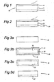
- FIG. 1 shows an example of the structure of a solar cell produced by a method according to an embodiment of the invention.
- a solar cell 10 comprises a n-type Silicon substrate 11 having a Boron-diffused layer 12 at one side and a Phosphorus-diffused layer 13 at the other side. It is noted that a practical solar cell structure also has metal contacts and an anti-reflection coating, but those components are not shown in the Figures.
- Figure 2 shows another example in which a substrate 21 of p-type Silicon is processed so as to produce a Phosphorus-diffused layer 22 at one side and a Boron-diffused layer 23 at the other side.
- the solar cell of Figure 1 is the preferred embodiment because its device performance is better than the one of Figure 2 . In the description below, embodiments of the manufacturing method of the solar cell shown in Figure 1 (i.e. n-type substrate) are discussed.
- the first step of this method is making a P-diffused layer at one side of the substrate.
- a substrate 30 is heated at 800 ⁇ 900° C for 5 ⁇ 50 minutes in an atmosphere including a O 2 and P 2 O 5 vapor.
- all surfaces of the substrate 30 are covered with a SiO 2 film 31 comprising P 2 O 5 (hereafter, SiO 2 :P 2 O 5 ).
- This SiO 2 grows from Si of the substrate 30 and oxygen, and P 2 O 5 is incorporated into the SiO 2 film 31.
- the SiO 2 :P 2 O 5 film 31 is removed by dipping the substrate 30 in a 1 ⁇ 50% HF solution for about 0.5 ⁇ 10 minutes, or exposing the substrate 30 to a HF vapor, or etching it using reactive ion etching, see Figure 3C .
- the P-diffused layer 32 is etched out, except for one side, using a mixed solution of 1 ⁇ 30% HF and 0.1 ⁇ 50% HNO 3 , or etching it using reactive ion etching.
- One side etching is possible by sealing the other side of the substrate 30 with an etch-block coating or by just floating the substrate 30 on the solution.
- the substrate 30 now comprises a P-diffused layer 32' at one side, see Figure 3D .
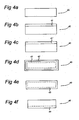
- FIG. 4A-4F An alternative method for manufacturing a P-diffused layer at one side of a substrate is explained with reference to Figure 4A-4F .
- one side of the surface of a substrate 40 is coated with either of liquid, paste, or gel 41 which includes P 2 O 5 and SiO 2 fine particles by either of spin-coating, spray-coating, or printing, see Figure 4B .
- the other sides of the substrate could be coated as well, but this does not influence the end result of this manufacturing method.
- the coating 41 is heated at 250 ⁇ 500 °C. The solvent evaporates or burns out when it includes organic matter.
- the P 2 O 5 and SiO 2 remain in the coating, see Figure 4C showing a coating 41'.
- the substrate 40 is heated at 800 ⁇ 900° C for 2 ⁇ 50 minutes.
- SiO 2 :P 2 O 5 see Figure 4D .
- the P diffuses into the Si core just like in Figure 3B , and a SiO 2 :P 2 O 5 film 42 and a P-diffused layer 43 are formed at all the surfaces of silicon substrate 40.
- the SiO 2 :P 2 O 5 film 42 is removed using a 1 ⁇ 50% HF solution or some other known method.
- the P-diffused layer is etched out, except the side firstly coated, using mixed solution of 1 ⁇ 0% HF and 0.1 ⁇ 50% HNO 3 , or reactive ion etching.
- One side etching is possible by sealing the other side with etch-block coating or just floating the substrate on the solution.
- Figure 4F depicts the substrate 40 having a P-diffused layer 44 at one side.
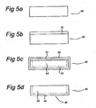
- a possible third method for manufacturing the P-diffused layer at one side of the substrate is explained with reference to Figure 5A-5D .
- First one side of a substrate 50 is blocked using a diffusion blocking layer on one side, see blocking layer 51.
- the blocking layer 51 can be formed using different processes listed below:
- P is diffused into a Si core 54 using the method as described with reference to Figure 3B or 4D .
- a SiO 2 :P 2 O 5 layer 52 is formed and P diffuses in, but the blocking layer 51 prevents the P form diffusing into the Si core 54 at one side, see Figure 5C .
- the SiO 2 :P 2 O 5 layer 52 and the blocking layer 51 are removed by dipping the substrate 50 in a 1% ⁇ 50% HF solution.
- the diffusion of P on just one side of the substrate is achieved using a back-to-back diffusion method in which two substrates are contacting each other at their surface. After the pre-diffusion of Phosphorus into the first side of the substrate, which was described above, that same first side of the substrate is blocked before the substrate is put in an oven for further processing.
- the first side 61 of the substrate 60 is blocked by a first side 62 of another substrate 63. That other substrate may be a similarly processed substrate, see Figure 6A .
- This way of blocking is referred to as back-to-back.
- One of the advantages of a back-to-back configuration is that less space is required in the oven as compared to blocking each substrate individually.
- Figure 6 B shows an alternative in which the substrate 60 is blocked by a substrate 65 that is not processed yet (i.e. a fresh substrate).
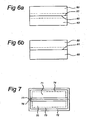
- the second side of the substrate is exposed to a Boron diffusion source.
- This Boron diffusion source may be a vapour source or a coating source.
- the substrate is heated for a certain period of time and to a certain temperature so as to diffuse Boron into the second side of the substrate and to simultaneously diffuse the Phosphorus further into said substrate (i.e. deeper than said initial depth).
- Successful results have been achieved with a Boron vapor source for the diffusion.
- Two substrates 70, 71 are put back-to-back into the oven and heated at 900 ⁇ 1000 °C for 30 ⁇ 120 minutes in an atmosphere including an O 2 and B 2 O 3 vapor, which may produced by leading N 2 through BBr 3 liquid.
- a SiO 2 film 72 which includes B 2 O 3 (hereafter, SiO 2 :B 2 O 3 ).
- B diffuses into Si until the depth of 0.01 ⁇ 1.0 ⁇ m to render B-diffused layers 73, 74.
- Part of the B 2 O 3 may sneak into the slight gap between the substrates 70, 71, but the impact is very small because of the existence of heavily diffused P at those areas.
- the P present in the P-diffused layers 76, 77 also diffuses further into the respective Si cores 70, 71 driven by the heat used. This will result in P-diffused layers that are deeper than their original depth.
- FIG. 8 shows a graph of solar cell efficiencies values fabricated on n-type multi crystalline substrates using the new method (as presented here) and the state-of-the-art method (see for example T.Buck et al., Proceedings of 21 st European Photovoltaic Solar energy Conference (4-8 September 2006, Dresden, Germany) p.1264-1267 ).
- Phosphorous is diffused-in deeper than when Phosphorous is diffused-in individually (not in a simultaneous diffusion with Boron).
- a Phosphorous concentration in the substrate at 0.5 ⁇ m depth can be more that 100 times higher than that at 5 ⁇ m depth.
- Phosphorous may also diffuse into the Silicon on the Boron-side because a small amount of Phosphorous will effuse from the Phosphorous-side to the opposite side (i.e. the Boron-diffused side).
- the amount of the Phosphorous diffused-in is smaller than that of the Boron diffused-in, and the diffused layer can easily satisfy the proper conditions for a p-type emitter.
- the amount of the Phosphorous diffused-in is still larger than the background doping of the substrate.
- the Phosphorous concentration at 0.2 ⁇ m deep may be more than 100 times higher than that at 5 ⁇ m deep.
- the invention enables the manufacturing of a Boron doping profile which satisfies the required conditions for an emitter, without allowing Phosphorous of larger quantity than Boron to diffuse into the Boron-diffused side and without allowing Boron of larger quantity than Phosphorous to diffuse into the Phosphorous-diffused side.
Landscapes
- Engineering & Computer Science (AREA)
- Manufacturing & Machinery (AREA)
- Physics & Mathematics (AREA)
- Condensed Matter Physics & Semiconductors (AREA)
- Electromagnetism (AREA)
- General Physics & Mathematics (AREA)
- Computer Hardware Design (AREA)
- Microelectronics & Electronic Packaging (AREA)
- Power Engineering (AREA)
- Photovoltaic Devices (AREA)
Abstract
Description
- The present invention relates to the manufacture of a solar cell using a crystalline silicon (Si) substrate. An example of such a solar cell is a Boron-emitter n-base solar cells with a back side field resulting from a Phosphorous-diffusion.
- When two kinds of diffusion processes (Boron and Phosphorous) are required, the higher temperature Boron-diffusion step is usually processed before the lower temperature Phosphorous-diffusion step, see for example T.Buck et al., Proceedings of 21 st European Photovoltaic Solar Energy Conference (4-8 September 2006, Dresden, Germany) p.1264-1267. Such a process sequence requires a special protective layer to block Phosphorous from diffusing into the Boron-diffused side during the time of the Phosphorous diffusion step. Sometimes Boron diffuses out from the Boron-diffused layer to this protective layer and is depleted near the interface. This causes an increase of the sheet resistance of the emitter which leads to an increase of the series resistance of the solar cell manufactured through this process. Furthermore, additional process steps are required to remove the protective layer, or the optimal properties of the protective layer are compromised if it is retained on the Silicon substrate (for example, as passivation and anti-reflection coating).
- On the other hand, if the Phosphorous diffusion step is processed before the Boron diffusion step, the Phosphorous-diffused side must be protected from Boron during the Boron diffusion step. Additionally, Phosphorous must be prevented sufficiently from diffusing into the Boron-side during the Phosphorous-diffusion because it cannot be easily compensated by Boron. Additionally, Phosphorous is effused from the Phosphorous-diffused layer at the temperature of the Boron diffusion and, therefore, Phosphorous is diffused together with Boron into the surface of the Boron-diffused layer. This hampers obtaining good properties of the Boron-doped emitter. Because of these difficulties, the Phosphorous diffusion prior to the Boron diffusion has hardly been attempted, or, when attempted, has not been successful in manufacturing a solar cell.
- Although it is possible to form both Boron and Phosphorous diffusions at the same time by some methods, such as printing each diffusion source on one side prior to the diffusion process, such a method results in a compensation of Boron by Phosphorous at least at the edge of the Boron-side, because Phosphorous diffuses faster and is more soluble in Silicon, and therefore easily compensates Boron.
- Other methods are known in which separate diffusions for Boron and Phosphorous are used, with wafers placed together in pairs. Two sides of two substrates touch each other to let them partly be protected from diffusion. This will limit the problems of compensation of Boron by Phosphorous, and vice versa, to the edge of the wafers. However, the edges of the wafers must subsequently be cut off, which significantly increases costs per Wp produced.
- It is an object of the present invention to provide a method of manufacturing a solar cell out of a Si substrate using both Boron and Phosphorus diffusion in which at least one of the problems mentioned above is solved.
- The object is achieved by a method of manufacturing a crystalline silicon solar cell in accordance with
claim 1, or claim 2 or claim 3 or claim 4 - The present invention involves stabilizing and reducing the effused Phosphorous in the atmosphere during the Boron diffusion process, by diffusing the Phosphorous already to some extent into the surface prior to the Boron diffusion. This enables to remove the Phosphorous diffusion source before the Boron diffusion. The amount of the effused Phosphorous from the diffusion source is larger and more fluctuating than that from the Silicon surface where Phosphorous is already diffused-in. Therefore, this process improves the quality and reproducibility of the Boron-diffused p-type emitter. It also avoids the creation of an n-type edge on the Boron-diffused side and therefore avoids shunting of the solar cell.
- In an aspect, the invention also relates to a solar cell manufactured by the method described above.
- Further advantages and characteristics of the present invention will become clear on the basis of a description of a number of embodiments, in which reference is made to the appended drawings, in which:
-
Figure 1 shows an example of the structure of a solar cell produced by a method according to an embodiment of the invention; -
Figure 2 shows another example in which a substrate of p-type Silicon; -
Figures 3A-3D diagrammatically show processing steps for making a P-diffused layer at one side of a substrate; -
Figures 4A-4F diagrammatically show processing steps of an alternative method for manufacturing a P-diffused layer at one side of a substrate; -
Figure 5A-5D diagrammatically show processing steps for a possible third method for manufacturing the P-diffused layer at one side of the substrate; -
Figures 6A, 6B shows two possible configurations for blocking one side of the substrate during a Boron diffusion step; -
Figure 7 diagrammatically shows a back-to-back configuration during a Boron diffusion step; -
Figure 8 is a graph showing the measured efficiency of solar cells produced by the method according to the invention as compared to state-of-the-art solar cells. -
Figure 1 shows an example of the structure of a solar cell produced by a method according to an embodiment of the invention. Asolar cell 10 comprises a n-type Silicon substrate 11 having a Boron-diffusedlayer 12 at one side and a Phosphorus-diffusedlayer 13 at the other side. It is noted that a practical solar cell structure also has metal contacts and an anti-reflection coating, but those components are not shown in the Figures.Figure 2 shows another example in which asubstrate 21 of p-type Silicon is processed so as to produce a Phosphorus-diffusedlayer 22 at one side and a Boron-diffusedlayer 23 at the other side. The solar cell ofFigure 1 is the preferred embodiment because its device performance is better than the one ofFigure 2 . In the description below, embodiments of the manufacturing method of the solar cell shown inFigure 1 (i.e. n-type substrate) are discussed. - The first step of this method is making a P-diffused layer at one side of the substrate. According to an embodiment, a
substrate 30 is heated at 800~900° C for 5~50 minutes in an atmosphere including a O2 and P2O5 vapor. Then, all surfaces of thesubstrate 30 are covered with a SiO2 film 31 comprising P2O5 (hereafter, SiO2:P2O5). This SiO2 grows from Si of thesubstrate 30 and oxygen, and P2O5 is incorporated into the SiO2 film 31. At the interface ofSilicon 33 and the SiO2:P2O5 film 31, P2O5 is reduced into P and P diffuses into the core of the substrate 30 (seecore 33 inFigure 3B ) until a depth of 0.01~1.0 µm. Thus far, the SiO2:P2O5 film 31 and a P-diffusedlayer 32 are formed at all the surface of thesilicon substrate 30. Next, the SiO2:P2O5 film 31 is removed by dipping thesubstrate 30 in a 1~50% HF solution for about 0.5~10 minutes, or exposing thesubstrate 30 to a HF vapor, or etching it using reactive ion etching, seeFigure 3C . Next, the P-diffusedlayer 32 is etched out, except for one side, using a mixed solution of 1~30% HF and 0.1~50% HNO3, or etching it using reactive ion etching. One side etching is possible by sealing the other side of thesubstrate 30 with an etch-block coating or by just floating thesubstrate 30 on the solution. As a result, thesubstrate 30 now comprises a P-diffused layer 32' at one side, seeFigure 3D . - An alternative method for manufacturing a P-diffused layer at one side of a substrate is explained with reference to
Figure 4A-4F . First, one side of the surface of asubstrate 40 is coated with either of liquid, paste, orgel 41 which includes P2O5 and SiO2 fine particles by either of spin-coating, spray-coating, or printing, seeFigure 4B . The other sides of the substrate could be coated as well, but this does not influence the end result of this manufacturing method. Next, thecoating 41 is heated at 250~500 °C. The solvent evaporates or burns out when it includes organic matter. The P2O5 and SiO2 remain in the coating, seeFigure 4C showing a coating 41'. Then in a further heating step, thesubstrate 40 is heated at 800~900° C for 2~50 minutes. As a result, all the surfaces are covered with SiO2:P2O5, seeFigure 4D . Oxygen from the atmosphere, and P2O5 from the first coating film 41' which goes out into the atmosphere. The P diffuses into the Si core just like inFigure 3B , and a SiO2:P2O5 film 42 and a P-diffusedlayer 43 are formed at all the surfaces ofsilicon substrate 40. Now, the SiO2:P2O5 film 42 is removed using a 1~50% HF solution or some other known method. The P-diffused layer is etched out, except the side firstly coated, using mixed solution of 1~0% HF and 0.1~50% HNO3, or reactive ion etching. One side etching is possible by sealing the other side with etch-block coating or just floating the substrate on the solution. The result is shown inFigure 4F which depicts thesubstrate 40 having a P-diffusedlayer 44 at one side. - A possible third method for manufacturing the P-diffused layer at one side of the substrate is explained with reference to
Figure 5A-5D . First one side of asubstrate 50 is blocked using a diffusion blocking layer on one side, seeblocking layer 51. Theblocking layer 51 can be formed using different processes listed below: - Coat the surface with either a liquid, paste, or gel which includes SiO2 or TiO2 or anything which does not diffuse into Silicon by spin-coating or spray-coating or printing. Heat the coating at 200~700°C, then the solvent evaporates.
- Heat the
substrate 50 at 850 ~ 1100°C in a O2 or O2+H2O atmosphere for 0.5 ~ several hours. Then a SiO2 film which is thicker than 0.1 µm is formed on all the surfaces. Remove the film on just one side by dipping thesubstrate 50 in a 1~10%HF solution. - Deposit >0.1 µm thick SiO2 or SiN or TiO2 or anything like that using chemical vapor deposition.
- In a next step, P is diffused into a
Si core 54 using the method as described with reference toFigure 3B or4D . A SiO2:P2O5 layer 52 is formed and P diffuses in, but theblocking layer 51 prevents the P form diffusing into theSi core 54 at one side, seeFigure 5C . Then, the SiO2:P2O5 layer 52 and theblocking layer 51 are removed by dipping thesubstrate 50 in a 1%~50% HF solution. - According to another embodiment, the diffusion of P on just one side of the substrate is achieved using a back-to-back diffusion method in which two substrates are contacting each other at their surface.
After the pre-diffusion of Phosphorus into the first side of the substrate, which was described above, that same first side of the substrate is blocked before the substrate is put in an oven for further processing. In an embodiment, thefirst side 61 of thesubstrate 60 is blocked by afirst side 62 of anothersubstrate 63. That other substrate may be a similarly processed substrate, seeFigure 6A . This way of blocking is referred to as back-to-back. One of the advantages of a back-to-back configuration is that less space is required in the oven as compared to blocking each substrate individually. Furthermore, the escape of phosphorus from thefirst side 61 is most effectively prevented because the facing substrate also has high phosphorus concentration, which keeps phosphorus concentration in better condition.Figure 6 B shows an alternative in which thesubstrate 60 is blocked by asubstrate 65 that is not processed yet (i.e. a fresh substrate). - In the oven, the second side of the substrate is exposed to a Boron diffusion source. This Boron diffusion source may be a vapour source or a coating source. In the oven the substrate is heated for a certain period of time and to a certain temperature so as to diffuse Boron into the second side of the substrate and to simultaneously diffuse the Phosphorus further into said substrate (i.e. deeper than said initial depth). Successful results have been achieved with a Boron vapor source for the diffusion. Below, a specific description of an embodiment is described with reference to
Figure 7 . Twosubstrates Si cores layers substrates layers respective Si cores - The Boron diffusion of the example of
Figure 7 used vapor source diffusion, it will be clear to the skilled person that this method is also effective in the case of a coating source diffusion like described in the phosphorus diffusion step ofFigures 4A-4F . - The combination of a pre-diffusion of Phosphorous with a further diffusion during the simultaneous diffusion of Boron and Phosphorous, leads to a solar cell having very good properties, as can be seen from
Figure 8. Figure 8 shows a graph of solar cell efficiencies values fabricated on n-type multi crystalline substrates using the new method (as presented here) and the state-of-the-art method (see for example T.Buck et al., Proceedings of 21 st European Photovoltaic Solar energy Conference (4-8 September 2006, Dresden, Germany) p.1264-1267). - As a consequence of the manufacturing method described above, Phosphorous is diffused-in deeper than when Phosphorous is diffused-in individually (not in a simultaneous diffusion with Boron). When using the invention, a Phosphorous concentration in the substrate at 0.5 µm depth can be more that 100 times higher than that at 5 µm depth.
- In the method according to the invention, Phosphorous may also diffuse into the Silicon on the Boron-side because a small amount of Phosphorous will effuse from the Phosphorous-side to the opposite side (i.e. the Boron-diffused side). However, on the Boron-side, the amount of the Phosphorous diffused-in is smaller than that of the Boron diffused-in, and the diffused layer can easily satisfy the proper conditions for a p-type emitter.
- The amount of the Phosphorous diffused-in is still larger than the background doping of the substrate. The Phosphorous concentration at 0.2 µm deep may be more than 100 times higher than that at 5 µm deep.
- The invention enables the manufacturing of a Boron doping profile which satisfies the required conditions for an emitter, without allowing Phosphorous of larger quantity than Boron to diffuse into the Boron-diffused side and without allowing Boron of larger quantity than Phosphorous to diffuse into the Phosphorous-diffused side.
- It will be understood that variants will occur to those skilled in the art on reading the above text. Those variants are deemed to lie within the scope of the invention as described in the appended claims.
Claims (16)
- Method of manufacturing a crystalline silicon solar cell, subsequently comprising:- providing a crystalline silicon substrate having a first side and a second side opposite said first side;- pre-diffusing Phosphorus into said first side of said substrate which renders a film comprising SiO2 and P2O5 and a Phosphorus diffused layer having an initial depth, comprising the step of:- heating said substrate in an atmosphere including O2 and P2O5 so as to produce the film comprising SiO2 and P2O5, and an intermediate Phosphorus diffused layer on all sides of said substrate;- removing said SiO2:P2O5 film from all sides of said substrate;- etching out said a Phosphorus diffused layer except for said first side;- blocking said first side of said substrate;- exposing said second side of said substrate to a Boron diffusion source;- heating said substrate for a certain period of time and to a certain temperature so as to diffuse Boron into said second side of said substrate and to simultaneously diffuse said Phosphorus further into said substrate.
- Method of manufacturing a crystalline silicon solar cell, subsequently comprising:- providing a crystalline silicon substrate having a first side and a second side opposite said first side;- pre-diffusing Phosphorus into said first side of said substrate which renders a film comprising SiO2 and P2O5 and a Phosphorus diffused layer having an initial depth, comprising the step of:- forming a coating on said first side using a screen-printed method, a single side spin-on method, or a single side spray-on method, said coating comprising P2O5 and SiO2;- heating said substrate so as to produce the film comprising SiO2 and P2O5, and an intermediate Phosphorus diffused layer on all sides of said substrate;- removing said SiO2:P2O5 film from all sides of said substrate;- etching out said a Phosphorus diffused layer except for said first side- blocking said first side of said substrate;- exposing said second side of said substrate to a Boron diffusion source;- heating said substrate for a certain period of time and to a certain temperature so as to diffuse Boron into said second side of said substrate and to simultaneously diffuse said Phosphorus further into said substrate.
- Method of manufacturing a crystalline silicon solar cell, subsequently comprising:- providing a crystalline silicon substrate having a first side and a second side opposite said first side;- pre-diffusing Phosphorus into said first side of said substrate which renders a film comprising SiO2 and P2O5 and a Phosphorus diffused layer having an initial depth, comprising the step of:- blocking said second side of said substrate;- heating said substrate in an atmosphere including O2 and P2O5 so as to produce the film comprising SiO2 and P2O5, and an intermediate Phosphorus diffused layer on all sides of said substrate;- removing said SiO2:P2O5 film from all sides of said substrate- blocking said first side of said substrate;- exposing said second side of said substrate to a Boron diffusion source;- heating said substrate for a certain period of time and to a certain temperature so as to diffuse Boron into said second side of said substrate and to simultaneously diffuse said Phosphorus further into said substrate.
- Method of manufacturing a crystalline silicon solar cell, subsequently comprising:- providing a crystalline silicon substrate having a first side and a second side opposite said first side;- pre-diffusing Phosphorus into said first side of said substrate which renders a film comprising SiO2 and P2O5 and a Phosphorus diffused layer having an initial depth, comprising the step of :- blocking said second side of said substrate;- forming a coating on said first side using a screen-printed method, a single side spin-on method, or a single side spray-on method, said coating comprising P2O5 and SiO2;- heating said substrate so as to produce the film comprising SiO2 and P2O5, and a Phosphorus diffused layer on all sides of said substrate;- removing said SiO2:P2O5 film from all sides of said substrate;- blocking said first side of said substrate;- exposing said second side of said substrate to a Boron diffusion source;- heating said substrate for a certain period of time and to a certain temperature so as to diffuse Boron into said second side of said substrate and to simultaneously diffuse said Phosphorus further into said substrate.
- Method according to any one of the claims 1-4, wherein heating said substrate is at a temperature of 800~900°C.
- Method according to claims 3 or 4, wherein said second side of said substrate is blocked by way of forming a diffusion blocking layer on said second side.
- Method according to claims 3 or 4, wherein said second side of said substrate is blocked by another substrate.
- Method according to any of the preceding claims, wherein said first side of said substrate is blocked by a first side of another substrate.
- Method according to claim 8, wherein said other substrate comprises a processed substrate which is at the time of said blocking, similarly processed as said substrate.
- Method according to any of the claims 1-4 or 6-7, wherein said first side of said substrate is blocked by way of covering said first side of said substrate with a coating layer.
- Method according to any of the preceding claims, wherein said exposing of said second side of said substrate to a Boron diffusion source comprises exposing said substrate to an atmosphere including O2 and B2O3.
- Method according to claim 11, wherein said certain period of time lies between 30-120 minutes.
- Method according to claim 11 or 12, wherein said certain temperature lies between 900-1000 °C.
- Method according to claim 11 or 12, wherein said B2O3 is produced by leading N2 through a BBr3 liquid.
- A solar cell manufactured by a method according to any of the preceding claims, characterised in that a Phosphorus concentration at 0.5 µm depth of said first side in said substrate is more than 100 times higher than the Phosphorus concentration at 5 µm depth of said side.
- A solar cell according to claim 15, wherein the Phosphorus concentration at 0.2 µm depth of said second side in said substrate is more than 100 times higher than the Phosphorus concentration at 5 µm depth of said side.
Applications Claiming Priority (2)
| Application Number | Priority Date | Filing Date | Title |
|---|---|---|---|
| NL2000999A NL2000999C2 (en) | 2007-11-13 | 2007-11-13 | Process for the production of crystalline silicon solar cells using co-diffusion of boron and phosphorus. |
| PCT/NL2008/050724 WO2009064183A1 (en) | 2007-11-13 | 2008-11-13 | Method of manufacturing crystalline silicon solar cells using co diffusion of boron and phosphorus |
Publications (3)
| Publication Number | Publication Date |
|---|---|
| EP2210283A1 EP2210283A1 (en) | 2010-07-28 |
| EP2210283B1 EP2210283B1 (en) | 2011-10-19 |
| EP2210283B2 true EP2210283B2 (en) | 2015-07-15 |
Family
ID=39473196
Family Applications (1)
| Application Number | Title | Priority Date | Filing Date |
|---|---|---|---|
| EP08849334.1A Active EP2210283B2 (en) | 2007-11-13 | 2008-11-13 | Method of manufacturing crystalline silicon solar cells using co diffusion of boron and phosphorus |
Country Status (10)
| Country | Link |
|---|---|
| US (1) | US8445312B2 (en) |
| EP (1) | EP2210283B2 (en) |
| JP (1) | JP2011503896A (en) |
| KR (1) | KR101515255B1 (en) |
| CN (1) | CN101919070B (en) |
| AT (1) | ATE529897T1 (en) |
| AU (1) | AU2008321599A1 (en) |
| ES (1) | ES2375324T3 (en) |
| NL (1) | NL2000999C2 (en) |
| WO (1) | WO2009064183A1 (en) |
Families Citing this family (27)
| Publication number | Priority date | Publication date | Assignee | Title |
|---|---|---|---|---|
| US8518170B2 (en) | 2008-12-29 | 2013-08-27 | Honeywell International Inc. | Boron-comprising inks for forming boron-doped regions in semiconductor substrates using non-contact printing processes and methods for fabricating such boron-comprising inks |
| KR101119916B1 (en) * | 2009-08-24 | 2012-03-13 | 삼성전자주식회사 | Electronic device utilizing graphene electrodes and organic/inorganic hybrid composites and method for manufacturing the same |
| JP4868079B1 (en) * | 2010-01-25 | 2012-02-01 | 日立化成工業株式会社 | N-type diffusion layer forming composition, n-type diffusion layer manufacturing method, and solar cell manufacturing method |
| US20130089944A1 (en) * | 2010-06-11 | 2013-04-11 | Amtech Systems, Inc. | Solar cell silicon wafer process |
| US20120122265A1 (en) * | 2010-11-17 | 2012-05-17 | Hitachi Chemical Company, Ltd. | Method for producing photovoltaic cell |
| WO2012108766A2 (en) | 2011-02-08 | 2012-08-16 | Tsc Solar B.V. | A method of manufactering a solar cell and a solar cell |
| CN102191562B (en) * | 2011-04-25 | 2012-08-29 | 苏州阿特斯阳光电力科技有限公司 | Boron diffusion method for N-type crystalline silica solar cell |
| CN102263159A (en) * | 2011-05-31 | 2011-11-30 | 江阴鑫辉太阳能有限公司 | Process for preparing n-type solar cell by utilizing boron-phosphorus coamplification |
| KR20140041865A (en) * | 2011-07-19 | 2014-04-04 | 히타치가세이가부시끼가이샤 | Composition that forms n-type diffusion layer, n-type diffusion layer manufacturing method and solar cell element manufacturing method |
| JPWO2013015173A1 (en) * | 2011-07-25 | 2015-02-23 | 日立化成株式会社 | Solar cell substrate, method for manufacturing solar cell substrate, solar cell element, and solar cell |
| US8629294B2 (en) | 2011-08-25 | 2014-01-14 | Honeywell International Inc. | Borate esters, boron-comprising dopants, and methods of fabricating boron-comprising dopants |
| US8975170B2 (en) | 2011-10-24 | 2015-03-10 | Honeywell International Inc. | Dopant ink compositions for forming doped regions in semiconductor substrates, and methods for fabricating dopant ink compositions |
| DE102013102573A1 (en) | 2012-03-13 | 2013-09-19 | centrotherm cell & module GmbH | Method for manufacturing solar cell e.g. interdigitated-back contact solar cell, involves cleaning cell substrate, and diffusing boron from boron source layer and diffusing phosphorus into solar cell substrate in common diffusion step |
| DE102013102574A1 (en) | 2012-03-13 | 2013-09-19 | centrotherm cell & module GmbH | Method for manufacturing back contact solar cell, involves diffusing second type dopant containing paste into solar cell substrate in common-emitter type impurity regions by sintering second type dopant containing paste |
| CN104205361B (en) | 2012-03-20 | 2017-07-04 | 泰姆普雷斯艾普公司 | The method for manufacturing solar cell |
| CN102683492B (en) * | 2012-05-27 | 2014-10-15 | 苏州阿特斯阳光电力科技有限公司 | Preparation method of double-sided back contact crystalline silicon solar cell |
| CN102797040B (en) * | 2012-08-22 | 2015-08-12 | 中国科学院电工研究所 | A kind of method of boron (B) diffusing, doping |
| US8722545B2 (en) * | 2012-08-27 | 2014-05-13 | Stmicroelectronics Pte Ltd. | Method of selectively deglazing P205 |
| JP6114108B2 (en) * | 2013-05-20 | 2017-04-12 | 信越化学工業株式会社 | Manufacturing method of solar cell |
| KR20150007394A (en) * | 2013-07-10 | 2015-01-21 | 현대중공업 주식회사 | Method for fabricating bi-facial solar cell |
| CN104157740B (en) * | 2014-09-03 | 2017-02-08 | 苏州阿特斯阳光电力科技有限公司 | N-type two-side solar cell manufacturing method |
| DE102015226516B4 (en) * | 2015-12-22 | 2018-02-22 | Fraunhofer-Gesellschaft zur Förderung der angewandten Forschung eingetragener Verein | Method for doping semiconductor substrates by means of a co-diffusion process |
| JP6356855B2 (en) * | 2017-03-16 | 2018-07-11 | 信越化学工業株式会社 | Manufacturing method of solar cell |
| TW201903851A (en) * | 2017-06-13 | 2019-01-16 | 日商東京應化工業股份有限公司 | Manufacturing method of tantalum substrate for solar cell element |
| CN109301031B (en) * | 2018-09-12 | 2021-08-31 | 江苏林洋光伏科技有限公司 | Manufacturing method of N-type double-sided battery |
| CN110085699A (en) * | 2019-04-22 | 2019-08-02 | 通威太阳能(成都)有限公司 | A kind of p-type high-efficiency battery and preparation method thereof with passivation contact structures |
| CN110233180A (en) * | 2019-06-02 | 2019-09-13 | 苏州腾晖光伏技术有限公司 | The preparation method of p-type back side tunnel oxide passivation contact solar cell |
Citations (6)
| Publication number | Priority date | Publication date | Assignee | Title |
|---|---|---|---|---|
| US5468652A (en) † | 1993-07-14 | 1995-11-21 | Sandia Corporation | Method of making a back contacted solar cell |
| US5665175A (en) † | 1990-05-30 | 1997-09-09 | Safir; Yakov | Bifacial solar cell |
| EP0999598A1 (en) † | 1998-11-04 | 2000-05-10 | Shin-Etsu Chemical Co., Ltd. | Solar cell and method for fabricating a solar cell |
| US20010050404A1 (en) † | 2000-06-02 | 2001-12-13 | Honda Giken Kogyo Kabushiki Kaisha | Solar cell and method of manufacturing the same |
| US20050133084A1 (en) † | 2003-10-10 | 2005-06-23 | Toshio Joge | Silicon solar cell and production method thereof |
| EP1575087A2 (en) † | 2000-11-29 | 2005-09-14 | Origin Energy Solar Pty.Ltd | Semiconductor wafer processing to increase the usable planar surface area |
Family Cites Families (20)
| Publication number | Priority date | Publication date | Assignee | Title |
|---|---|---|---|---|
| US4451969A (en) * | 1983-01-10 | 1984-06-05 | Mobil Solar Energy Corporation | Method of fabricating solar cells |
| US4557037A (en) * | 1984-10-31 | 1985-12-10 | Mobil Solar Energy Corporation | Method of fabricating solar cells |
| US5082791A (en) * | 1988-05-13 | 1992-01-21 | Mobil Solar Energy Corporation | Method of fabricating solar cells |
| US5792280A (en) * | 1994-05-09 | 1998-08-11 | Sandia Corporation | Method for fabricating silicon cells |
| JP4812147B2 (en) * | 1999-09-07 | 2011-11-09 | 株式会社日立製作所 | Manufacturing method of solar cell |
| DE10021440A1 (en) * | 2000-05-03 | 2001-11-15 | Univ Konstanz | Process for producing a solar cell and solar cell produced by this process |
| US7435361B2 (en) * | 2005-04-14 | 2008-10-14 | E.I. Du Pont De Nemours And Company | Conductive compositions and processes for use in the manufacture of semiconductor devices |
| JP4657068B2 (en) * | 2005-09-22 | 2011-03-23 | シャープ株式会社 | Manufacturing method of back junction solar cell |
| US20080057220A1 (en) * | 2006-01-31 | 2008-03-06 | Robert Bachrach | Silicon photovoltaic cell junction formed from thin film doping source |
| JP2008112847A (en) * | 2006-10-30 | 2008-05-15 | Shin Etsu Chem Co Ltd | Process for manufacturing single crystal silicon solar cell and single crystal silicon solar cell |
| WO2009052343A1 (en) * | 2007-10-18 | 2009-04-23 | E. I. Du Pont De Nemours And Company | Conductive compositions and processes for use in the manufacture of semiconductor devices: flux materials |
| DE102008019402A1 (en) * | 2008-04-14 | 2009-10-15 | Gebr. Schmid Gmbh & Co. | Process for the selective doping of silicon and silicon substrate treated therewith |
| WO2010009295A2 (en) * | 2008-07-16 | 2010-01-21 | Applied Materials, Inc. | Hybrid heterojunction solar cell fabrication using a metal layer mask |
| US7838400B2 (en) * | 2008-07-17 | 2010-11-23 | Applied Materials, Inc. | Rapid thermal oxide passivated solar cell with improved junction |
| US8231934B2 (en) * | 2008-11-26 | 2012-07-31 | E. I. Du Pont De Nemours And Company | Conductive paste for solar cell electrode |
| US20120227794A1 (en) * | 2009-09-18 | 2012-09-13 | Applied Materials, Inc. | Threshold adjustment implants for reducing surface recombination in solar cells |
| TWI496312B (en) * | 2009-10-26 | 2015-08-11 | Newsouth Innovations Pty Ltd | Improved metallisation method for silicon solar cells |
| US8586862B2 (en) * | 2009-11-18 | 2013-11-19 | Solar Wind Technologies, Inc. | Method of manufacturing photovoltaic cells, photovoltaic cells produced thereby and uses thereof |
| KR101141578B1 (en) * | 2010-09-14 | 2012-05-17 | (주)세미머티리얼즈 | Method for manufacturing a Solar Cell |
| CN103477450A (en) * | 2011-04-21 | 2013-12-25 | 应用材料公司 | Method of forming P-N junction in solar cell substrate |
-
2007
- 2007-11-13 NL NL2000999A patent/NL2000999C2/en not_active IP Right Cessation
-
2008
- 2008-11-13 JP JP2010533981A patent/JP2011503896A/en active Pending
- 2008-11-13 EP EP08849334.1A patent/EP2210283B2/en active Active
- 2008-11-13 CN CN2008801241277A patent/CN101919070B/en active Active
- 2008-11-13 AU AU2008321599A patent/AU2008321599A1/en not_active Abandoned
- 2008-11-13 ES ES08849334T patent/ES2375324T3/en active Active
- 2008-11-13 WO PCT/NL2008/050724 patent/WO2009064183A1/en active Application Filing
- 2008-11-13 US US12/742,682 patent/US8445312B2/en active Active
- 2008-11-13 AT AT08849334T patent/ATE529897T1/en not_active IP Right Cessation
- 2008-11-13 KR KR1020107012964A patent/KR101515255B1/en active IP Right Grant
Patent Citations (6)
| Publication number | Priority date | Publication date | Assignee | Title |
|---|---|---|---|---|
| US5665175A (en) † | 1990-05-30 | 1997-09-09 | Safir; Yakov | Bifacial solar cell |
| US5468652A (en) † | 1993-07-14 | 1995-11-21 | Sandia Corporation | Method of making a back contacted solar cell |
| EP0999598A1 (en) † | 1998-11-04 | 2000-05-10 | Shin-Etsu Chemical Co., Ltd. | Solar cell and method for fabricating a solar cell |
| US20010050404A1 (en) † | 2000-06-02 | 2001-12-13 | Honda Giken Kogyo Kabushiki Kaisha | Solar cell and method of manufacturing the same |
| EP1575087A2 (en) † | 2000-11-29 | 2005-09-14 | Origin Energy Solar Pty.Ltd | Semiconductor wafer processing to increase the usable planar surface area |
| US20050133084A1 (en) † | 2003-10-10 | 2005-06-23 | Toshio Joge | Silicon solar cell and production method thereof |
Non-Patent Citations (3)
| Title |
|---|
| J. Y. LEE: "Rapid Thermal Processing of Silicon Solar Cells-Passivation and Diffusion", 2003, pages: 1 - 164 † |
| K.R. MCINTOSH: "Lumps, Humps and Bumps: Three Detrimental Effects in the Current-Voltage Curve of Silicon Solar Cells", January 2001, pages: 1 - 180 † |
| S. SIVOTHTHAMAN ET AL.: "Fabrication of large area silicon solar cells by rapid thermal processing", APPLIED PHYSICS LETTERS, vol. 67, no. 16, 16 October 1995 (1995-10-16), pages 2335 - 2337, XP000544370, DOI: doi:10.1063/1.114336 † |
Also Published As
| Publication number | Publication date |
|---|---|
| NL2000999C2 (en) | 2009-05-14 |
| ATE529897T1 (en) | 2011-11-15 |
| WO2009064183A1 (en) | 2009-05-22 |
| CN101919070A (en) | 2010-12-15 |
| AU2008321599A1 (en) | 2009-05-22 |
| CN101919070B (en) | 2012-10-10 |
| KR20100102113A (en) | 2010-09-20 |
| US8445312B2 (en) | 2013-05-21 |
| EP2210283A1 (en) | 2010-07-28 |
| KR101515255B1 (en) | 2015-04-24 |
| US20100319771A1 (en) | 2010-12-23 |
| EP2210283B1 (en) | 2011-10-19 |
| JP2011503896A (en) | 2011-01-27 |
| ES2375324T3 (en) | 2012-02-28 |
Similar Documents
| Publication | Publication Date | Title |
|---|---|---|
| EP2210283B2 (en) | Method of manufacturing crystalline silicon solar cells using co diffusion of boron and phosphorus | |
| JP4335668B2 (en) | Manufacturing method of solar cell | |
| KR102055472B1 (en) | Ion implantation of dopants for forming spatially located diffusion regions of solar cells | |
| US20150243806A1 (en) | Method for fabricating back-contact type solar cell | |
| CN101681936A (en) | Method for cleaning a solar cell surface opening made with a solar etch paste | |
| AU2013200622B2 (en) | Solar cell and method of manufacturing the same | |
| CN107591461B (en) | Diffusion process for preparing solar cell | |
| Ebong et al. | High efficiency inline diffused emitter (ILDE) solar cells on mono‐crystalline CZ silicon | |
| US20170133545A1 (en) | Passivated contacts for photovoltaic cells | |
| EP3685446B1 (en) | Dopant enhanced solar cell and method of manufacturing thereof | |
| KR20150105369A (en) | Method of providing a boron doped region in a substrate and a solar cell using such a substrate | |
| EP3427303A1 (en) | Solar cell with doped polysilicon surface areas and method for manufacturing thereof | |
| GB2077996A (en) | Method of manufacturing solar cells | |
| WO2011160819A2 (en) | Method for fabrication of a back side contact solar cell | |
| KR101160116B1 (en) | Method of manufacturing Back junction solar cell | |
| KR20160061409A (en) | Method for producing a solar cell | |
| US9330917B2 (en) | Passivation layer for workpieces formed from a polymer | |
| KR101162123B1 (en) | Method for forming a selective emitter using doping mask with dopant and Method for manufacturing Solar cell thereof | |
| KR100995654B1 (en) | Solar cell and method for manufacturing the same | |
| JP2011159872A (en) | Method of manufacturing electrode, method of manufacturing solar cell, and device of manufacturing photoelectric conversion element | |
| US20170330990A1 (en) | Method for manufacturing photovoltaic device | |
| US20110036398A1 (en) | Method for manufacturing a semiconductor component | |
| US20140273330A1 (en) | Method of forming single side textured semiconductor workpieces | |
| KR20150024485A (en) | Method for fabricating Passivated Emitter with Rear Locally diffused cell | |
| KR101061681B1 (en) | Method for fabricating solar cell |
Legal Events
| Date | Code | Title | Description |
|---|---|---|---|
| PUAI | Public reference made under article 153(3) epc to a published international application that has entered the european phase |
Free format text: ORIGINAL CODE: 0009012 |
|
| 17P | Request for examination filed |
Effective date: 20100512 |
|
| AK | Designated contracting states |
Kind code of ref document: A1 Designated state(s): AT BE BG CH CY CZ DE DK EE ES FI FR GB GR HR HU IE IS IT LI LT LU LV MC MT NL NO PL PT RO SE SI SK TR |
|
| AX | Request for extension of the european patent |
Extension state: AL BA MK RS |
|
| DAX | Request for extension of the european patent (deleted) | ||
| GRAP | Despatch of communication of intention to grant a patent |
Free format text: ORIGINAL CODE: EPIDOSNIGR1 |
|
| GRAS | Grant fee paid |
Free format text: ORIGINAL CODE: EPIDOSNIGR3 |
|
| GRAA | (expected) grant |
Free format text: ORIGINAL CODE: 0009210 |
|
| AK | Designated contracting states |
Kind code of ref document: B1 Designated state(s): AT BE BG CH CY CZ DE DK EE ES FI FR GB GR HR HU IE IS IT LI LT LU LV MC MT NL NO PL PT RO SE SI SK TR |
|
| REG | Reference to a national code |
Ref country code: GB Ref legal event code: FG4D |
|
| REG | Reference to a national code |
Ref country code: CH Ref legal event code: EP |
|
| REG | Reference to a national code |
Ref country code: IE Ref legal event code: FG4D |
|
| REG | Reference to a national code |
Ref country code: DE Ref legal event code: R096 Ref document number: 602008010665 Country of ref document: DE Effective date: 20120112 |
|
| REG | Reference to a national code |
Ref country code: NL Ref legal event code: T3 |
|
| PGFP | Annual fee paid to national office [announced via postgrant information from national office to epo] |
Ref country code: FR Payment date: 20111214 Year of fee payment: 4 Ref country code: ES Payment date: 20111228 Year of fee payment: 4 |
|
| REG | Reference to a national code |
Ref country code: ES Ref legal event code: FG2A Ref document number: 2375324 Country of ref document: ES Kind code of ref document: T3 Effective date: 20120228 |
|
| LTIE | Lt: invalidation of european patent or patent extension |
Effective date: 20111019 |
|
| REG | Reference to a national code |
Ref country code: AT Ref legal event code: MK05 Ref document number: 529897 Country of ref document: AT Kind code of ref document: T Effective date: 20111019 |
|
| PG25 | Lapsed in a contracting state [announced via postgrant information from national office to epo] |
Ref country code: IS Free format text: LAPSE BECAUSE OF FAILURE TO SUBMIT A TRANSLATION OF THE DESCRIPTION OR TO PAY THE FEE WITHIN THE PRESCRIBED TIME-LIMIT Effective date: 20120219 Ref country code: NO Free format text: LAPSE BECAUSE OF FAILURE TO SUBMIT A TRANSLATION OF THE DESCRIPTION OR TO PAY THE FEE WITHIN THE PRESCRIBED TIME-LIMIT Effective date: 20120119 Ref country code: BE Free format text: LAPSE BECAUSE OF FAILURE TO SUBMIT A TRANSLATION OF THE DESCRIPTION OR TO PAY THE FEE WITHIN THE PRESCRIBED TIME-LIMIT Effective date: 20111019 Ref country code: LT Free format text: LAPSE BECAUSE OF FAILURE TO SUBMIT A TRANSLATION OF THE DESCRIPTION OR TO PAY THE FEE WITHIN THE PRESCRIBED TIME-LIMIT Effective date: 20111019 |
|
| PG25 | Lapsed in a contracting state [announced via postgrant information from national office to epo] |
Ref country code: LV Free format text: LAPSE BECAUSE OF FAILURE TO SUBMIT A TRANSLATION OF THE DESCRIPTION OR TO PAY THE FEE WITHIN THE PRESCRIBED TIME-LIMIT Effective date: 20111019 Ref country code: PT Free format text: LAPSE BECAUSE OF FAILURE TO SUBMIT A TRANSLATION OF THE DESCRIPTION OR TO PAY THE FEE WITHIN THE PRESCRIBED TIME-LIMIT Effective date: 20120220 Ref country code: SI Free format text: LAPSE BECAUSE OF FAILURE TO SUBMIT A TRANSLATION OF THE DESCRIPTION OR TO PAY THE FEE WITHIN THE PRESCRIBED TIME-LIMIT Effective date: 20111019 Ref country code: SE Free format text: LAPSE BECAUSE OF FAILURE TO SUBMIT A TRANSLATION OF THE DESCRIPTION OR TO PAY THE FEE WITHIN THE PRESCRIBED TIME-LIMIT Effective date: 20111019 Ref country code: HR Free format text: LAPSE BECAUSE OF FAILURE TO SUBMIT A TRANSLATION OF THE DESCRIPTION OR TO PAY THE FEE WITHIN THE PRESCRIBED TIME-LIMIT Effective date: 20111019 Ref country code: GR Free format text: LAPSE BECAUSE OF FAILURE TO SUBMIT A TRANSLATION OF THE DESCRIPTION OR TO PAY THE FEE WITHIN THE PRESCRIBED TIME-LIMIT Effective date: 20120120 |
|
| PG25 | Lapsed in a contracting state [announced via postgrant information from national office to epo] |
Ref country code: MC Free format text: LAPSE BECAUSE OF NON-PAYMENT OF DUE FEES Effective date: 20111130 Ref country code: CY Free format text: LAPSE BECAUSE OF FAILURE TO SUBMIT A TRANSLATION OF THE DESCRIPTION OR TO PAY THE FEE WITHIN THE PRESCRIBED TIME-LIMIT Effective date: 20111019 |
|
| PLBI | Opposition filed |
Free format text: ORIGINAL CODE: 0009260 |
|
| PG25 | Lapsed in a contracting state [announced via postgrant information from national office to epo] |
Ref country code: CZ Free format text: LAPSE BECAUSE OF FAILURE TO SUBMIT A TRANSLATION OF THE DESCRIPTION OR TO PAY THE FEE WITHIN THE PRESCRIBED TIME-LIMIT Effective date: 20111019 Ref country code: BG Free format text: LAPSE BECAUSE OF FAILURE TO SUBMIT A TRANSLATION OF THE DESCRIPTION OR TO PAY THE FEE WITHIN THE PRESCRIBED TIME-LIMIT Effective date: 20120119 Ref country code: EE Free format text: LAPSE BECAUSE OF FAILURE TO SUBMIT A TRANSLATION OF THE DESCRIPTION OR TO PAY THE FEE WITHIN THE PRESCRIBED TIME-LIMIT Effective date: 20111019 Ref country code: SK Free format text: LAPSE BECAUSE OF FAILURE TO SUBMIT A TRANSLATION OF THE DESCRIPTION OR TO PAY THE FEE WITHIN THE PRESCRIBED TIME-LIMIT Effective date: 20111019 Ref country code: DK Free format text: LAPSE BECAUSE OF FAILURE TO SUBMIT A TRANSLATION OF THE DESCRIPTION OR TO PAY THE FEE WITHIN THE PRESCRIBED TIME-LIMIT Effective date: 20111019 |
|
| 26 | Opposition filed |
Opponent name: Q-CELLS SE Effective date: 20120718 |
|
| PLAX | Notice of opposition and request to file observation + time limit sent |
Free format text: ORIGINAL CODE: EPIDOSNOBS2 |
|
| REG | Reference to a national code |
Ref country code: IE Ref legal event code: MM4A |
|
| PG25 | Lapsed in a contracting state [announced via postgrant information from national office to epo] |
Ref country code: PL Free format text: LAPSE BECAUSE OF FAILURE TO SUBMIT A TRANSLATION OF THE DESCRIPTION OR TO PAY THE FEE WITHIN THE PRESCRIBED TIME-LIMIT Effective date: 20111019 Ref country code: RO Free format text: LAPSE BECAUSE OF FAILURE TO SUBMIT A TRANSLATION OF THE DESCRIPTION OR TO PAY THE FEE WITHIN THE PRESCRIBED TIME-LIMIT Effective date: 20111019 |
|
| REG | Reference to a national code |
Ref country code: DE Ref legal event code: R026 Ref document number: 602008010665 Country of ref document: DE Effective date: 20120718 |
|
| PG25 | Lapsed in a contracting state [announced via postgrant information from national office to epo] |
Ref country code: IE Free format text: LAPSE BECAUSE OF NON-PAYMENT OF DUE FEES Effective date: 20111113 |
|
| PLAF | Information modified related to communication of a notice of opposition and request to file observations + time limit |
Free format text: ORIGINAL CODE: EPIDOSCOBS2 |
|
| PG25 | Lapsed in a contracting state [announced via postgrant information from national office to epo] |
Ref country code: AT Free format text: LAPSE BECAUSE OF FAILURE TO SUBMIT A TRANSLATION OF THE DESCRIPTION OR TO PAY THE FEE WITHIN THE PRESCRIBED TIME-LIMIT Effective date: 20111019 |
|
| PG25 | Lapsed in a contracting state [announced via postgrant information from national office to epo] |
Ref country code: MT Free format text: LAPSE BECAUSE OF FAILURE TO SUBMIT A TRANSLATION OF THE DESCRIPTION OR TO PAY THE FEE WITHIN THE PRESCRIBED TIME-LIMIT Effective date: 20111019 |
|
| PLBB | Reply of patent proprietor to notice(s) of opposition received |
Free format text: ORIGINAL CODE: EPIDOSNOBS3 |
|
| PG25 | Lapsed in a contracting state [announced via postgrant information from national office to epo] |
Ref country code: LU Free format text: LAPSE BECAUSE OF NON-PAYMENT OF DUE FEES Effective date: 20111113 |
|
| PG25 | Lapsed in a contracting state [announced via postgrant information from national office to epo] |
Ref country code: FI Free format text: LAPSE BECAUSE OF FAILURE TO SUBMIT A TRANSLATION OF THE DESCRIPTION OR TO PAY THE FEE WITHIN THE PRESCRIBED TIME-LIMIT Effective date: 20111019 |
|
| REG | Reference to a national code |
Ref country code: CH Ref legal event code: PL |
|
| GBPC | Gb: european patent ceased through non-payment of renewal fee |
Effective date: 20121113 |
|
| PG25 | Lapsed in a contracting state [announced via postgrant information from national office to epo] |
Ref country code: CH Free format text: LAPSE BECAUSE OF NON-PAYMENT OF DUE FEES Effective date: 20121130 Ref country code: LI Free format text: LAPSE BECAUSE OF NON-PAYMENT OF DUE FEES Effective date: 20121130 |
|
| REG | Reference to a national code |
Ref country code: FR Ref legal event code: ST Effective date: 20130731 |
|
| PG25 | Lapsed in a contracting state [announced via postgrant information from national office to epo] |
Ref country code: IT Free format text: LAPSE BECAUSE OF NON-PAYMENT OF DUE FEES Effective date: 20121113 |
|
| PG25 | Lapsed in a contracting state [announced via postgrant information from national office to epo] |
Ref country code: TR Free format text: LAPSE BECAUSE OF NON-PAYMENT OF DUE FEES Effective date: 20121112 Ref country code: HU Free format text: LAPSE BECAUSE OF FAILURE TO SUBMIT A TRANSLATION OF THE DESCRIPTION OR TO PAY THE FEE WITHIN THE PRESCRIBED TIME-LIMIT Effective date: 20111019 |
|
| PG25 | Lapsed in a contracting state [announced via postgrant information from national office to epo] |
Ref country code: GB Free format text: LAPSE BECAUSE OF NON-PAYMENT OF DUE FEES Effective date: 20121113 Ref country code: FR Free format text: LAPSE BECAUSE OF NON-PAYMENT OF DUE FEES Effective date: 20121130 |
|
| REG | Reference to a national code |
Ref country code: ES Ref legal event code: FD2A Effective date: 20140304 |
|
| PG25 | Lapsed in a contracting state [announced via postgrant information from national office to epo] |
Ref country code: ES Free format text: LAPSE BECAUSE OF NON-PAYMENT OF DUE FEES Effective date: 20121114 |
|
| REG | Reference to a national code |
Ref country code: NL Ref legal event code: PLED Effective date: 20150116 |
|
| PUAH | Patent maintained in amended form |
Free format text: ORIGINAL CODE: 0009272 |
|
| STAA | Information on the status of an ep patent application or granted ep patent |
Free format text: STATUS: PATENT MAINTAINED AS AMENDED |
|
| 27A | Patent maintained in amended form |
Effective date: 20150715 |
|
| AK | Designated contracting states |
Kind code of ref document: B2 Designated state(s): AT BE BG CH CY CZ DE DK EE ES FI FR GB GR HR HU IE IS IT LI LT LU LV MC MT NL NO PL PT RO SE SI SK TR |
|
| REG | Reference to a national code |
Ref country code: DE Ref legal event code: R102 Ref document number: 602008010665 Country of ref document: DE |
|
| REG | Reference to a national code |
Ref country code: NL Ref legal event code: T3 |
|
| REG | Reference to a national code |
Ref country code: NL Ref legal event code: RF Free format text: RIGHT OF PLEDGE, REMOVED Effective date: 20180413 |
|
| REG | Reference to a national code |
Ref country code: NL Ref legal event code: PD Owner name: NEDERLANDSE ORGANISATIE VOOR TOEGEPAST-NATUURWETEN Free format text: DETAILS ASSIGNMENT: CHANGE OF OWNER(S), ASSIGNMENT; FORMER OWNER NAME: STICHTING ENERGIEONDERZOEK CENTRUM NEDERLAND Effective date: 20190220 |
|
| P01 | Opt-out of the competence of the unified patent court (upc) registered |
Effective date: 20230522 |
|
| PGFP | Annual fee paid to national office [announced via postgrant information from national office to epo] |
Ref country code: NL Payment date: 20231120 Year of fee payment: 16 |
|
| PGFP | Annual fee paid to national office [announced via postgrant information from national office to epo] |
Ref country code: DE Payment date: 20231121 Year of fee payment: 16 |