EP2208877B1 - Dispositif de commande de moteur à combustion interne - Google Patents
Dispositif de commande de moteur à combustion interne Download PDFInfo
- Publication number
- EP2208877B1 EP2208877B1 EP08849001.6A EP08849001A EP2208877B1 EP 2208877 B1 EP2208877 B1 EP 2208877B1 EP 08849001 A EP08849001 A EP 08849001A EP 2208877 B1 EP2208877 B1 EP 2208877B1
- Authority
- EP
- European Patent Office
- Prior art keywords
- exhaust
- valve
- opening degree
- overlap period
- control
- Prior art date
- Legal status (The legal status is an assumption and is not a legal conclusion. Google has not performed a legal analysis and makes no representation as to the accuracy of the status listed.)
- Not-in-force
Links
Images


Classifications
-
- F—MECHANICAL ENGINEERING; LIGHTING; HEATING; WEAPONS; BLASTING
- F02—COMBUSTION ENGINES; HOT-GAS OR COMBUSTION-PRODUCT ENGINE PLANTS
- F02D—CONTROLLING COMBUSTION ENGINES
- F02D41/00—Electrical control of supply of combustible mixture or its constituents
- F02D41/0002—Controlling intake air
- F02D41/0007—Controlling intake air for control of turbo-charged or super-charged engines
-
- F—MECHANICAL ENGINEERING; LIGHTING; HEATING; WEAPONS; BLASTING
- F02—COMBUSTION ENGINES; HOT-GAS OR COMBUSTION-PRODUCT ENGINE PLANTS
- F02B—INTERNAL-COMBUSTION PISTON ENGINES; COMBUSTION ENGINES IN GENERAL
- F02B25/00—Engines characterised by using fresh charge for scavenging cylinders
- F02B25/14—Engines characterised by using fresh charge for scavenging cylinders using reverse-flow scavenging, e.g. with both outlet and inlet ports arranged near bottom of piston stroke
- F02B25/145—Engines characterised by using fresh charge for scavenging cylinders using reverse-flow scavenging, e.g. with both outlet and inlet ports arranged near bottom of piston stroke with intake and exhaust valves exclusively in the cylinder head
-
- F—MECHANICAL ENGINEERING; LIGHTING; HEATING; WEAPONS; BLASTING
- F02—COMBUSTION ENGINES; HOT-GAS OR COMBUSTION-PRODUCT ENGINE PLANTS
- F02D—CONTROLLING COMBUSTION ENGINES
- F02D13/00—Controlling the engine output power by varying inlet or exhaust valve operating characteristics, e.g. timing
- F02D13/02—Controlling the engine output power by varying inlet or exhaust valve operating characteristics, e.g. timing during engine operation
- F02D13/0203—Variable control of intake and exhaust valves
- F02D13/0215—Variable control of intake and exhaust valves changing the valve timing only
- F02D13/0219—Variable control of intake and exhaust valves changing the valve timing only by shifting the phase, i.e. the opening periods of the valves are constant
-
- F—MECHANICAL ENGINEERING; LIGHTING; HEATING; WEAPONS; BLASTING
- F02—COMBUSTION ENGINES; HOT-GAS OR COMBUSTION-PRODUCT ENGINE PLANTS
- F02D—CONTROLLING COMBUSTION ENGINES
- F02D13/00—Controlling the engine output power by varying inlet or exhaust valve operating characteristics, e.g. timing
- F02D13/02—Controlling the engine output power by varying inlet or exhaust valve operating characteristics, e.g. timing during engine operation
- F02D13/0261—Controlling the valve overlap
-
- F—MECHANICAL ENGINEERING; LIGHTING; HEATING; WEAPONS; BLASTING
- F02—COMBUSTION ENGINES; HOT-GAS OR COMBUSTION-PRODUCT ENGINE PLANTS
- F02D—CONTROLLING COMBUSTION ENGINES
- F02D15/00—Varying compression ratio
- F02D15/04—Varying compression ratio by alteration of volume of compression space without changing piston stroke
-
- F—MECHANICAL ENGINEERING; LIGHTING; HEATING; WEAPONS; BLASTING
- F02—COMBUSTION ENGINES; HOT-GAS OR COMBUSTION-PRODUCT ENGINE PLANTS
- F02D—CONTROLLING COMBUSTION ENGINES
- F02D23/00—Controlling engines characterised by their being supercharged
-
- F—MECHANICAL ENGINEERING; LIGHTING; HEATING; WEAPONS; BLASTING
- F02—COMBUSTION ENGINES; HOT-GAS OR COMBUSTION-PRODUCT ENGINE PLANTS
- F02D—CONTROLLING COMBUSTION ENGINES
- F02D41/00—Electrical control of supply of combustible mixture or its constituents
- F02D41/02—Circuit arrangements for generating control signals
- F02D41/04—Introducing corrections for particular operating conditions
- F02D41/10—Introducing corrections for particular operating conditions for acceleration
-
- F—MECHANICAL ENGINEERING; LIGHTING; HEATING; WEAPONS; BLASTING
- F02—COMBUSTION ENGINES; HOT-GAS OR COMBUSTION-PRODUCT ENGINE PLANTS
- F02B—INTERNAL-COMBUSTION PISTON ENGINES; COMBUSTION ENGINES IN GENERAL
- F02B29/00—Engines characterised by provision for charging or scavenging not provided for in groups F02B25/00, F02B27/00 or F02B33/00 - F02B39/00; Details thereof
- F02B29/04—Cooling of air intake supply
- F02B29/0406—Layout of the intake air cooling or coolant circuit
-
- F—MECHANICAL ENGINEERING; LIGHTING; HEATING; WEAPONS; BLASTING
- F02—COMBUSTION ENGINES; HOT-GAS OR COMBUSTION-PRODUCT ENGINE PLANTS
- F02D—CONTROLLING COMBUSTION ENGINES
- F02D41/00—Electrical control of supply of combustible mixture or its constituents
- F02D41/0002—Controlling intake air
- F02D2041/001—Controlling intake air for engines with variable valve actuation
-
- F—MECHANICAL ENGINEERING; LIGHTING; HEATING; WEAPONS; BLASTING
- F02—COMBUSTION ENGINES; HOT-GAS OR COMBUSTION-PRODUCT ENGINE PLANTS
- F02M—SUPPLYING COMBUSTION ENGINES IN GENERAL WITH COMBUSTIBLE MIXTURES OR CONSTITUENTS THEREOF
- F02M26/00—Engine-pertinent apparatus for adding exhaust gases to combustion-air, main fuel or fuel-air mixture, e.g. by exhaust gas recirculation [EGR] systems
- F02M26/02—EGR systems specially adapted for supercharged engines
- F02M26/04—EGR systems specially adapted for supercharged engines with a single turbocharger
- F02M26/05—High pressure loops, i.e. wherein recirculated exhaust gas is taken out from the exhaust system upstream of the turbine and reintroduced into the intake system downstream of the compressor
-
- F—MECHANICAL ENGINEERING; LIGHTING; HEATING; WEAPONS; BLASTING
- F02—COMBUSTION ENGINES; HOT-GAS OR COMBUSTION-PRODUCT ENGINE PLANTS
- F02M—SUPPLYING COMBUSTION ENGINES IN GENERAL WITH COMBUSTIBLE MIXTURES OR CONSTITUENTS THEREOF
- F02M26/00—Engine-pertinent apparatus for adding exhaust gases to combustion-air, main fuel or fuel-air mixture, e.g. by exhaust gas recirculation [EGR] systems
- F02M26/02—EGR systems specially adapted for supercharged engines
- F02M26/09—Constructional details, e.g. structural combinations of EGR systems and supercharger systems; Arrangement of the EGR and supercharger systems with respect to the engine
- F02M26/10—Constructional details, e.g. structural combinations of EGR systems and supercharger systems; Arrangement of the EGR and supercharger systems with respect to the engine having means to increase the pressure difference between the exhaust and intake system, e.g. venturis, variable geometry turbines, check valves using pressure pulsations or throttles in the air intake or exhaust system
-
- F—MECHANICAL ENGINEERING; LIGHTING; HEATING; WEAPONS; BLASTING
- F02—COMBUSTION ENGINES; HOT-GAS OR COMBUSTION-PRODUCT ENGINE PLANTS
- F02M—SUPPLYING COMBUSTION ENGINES IN GENERAL WITH COMBUSTIBLE MIXTURES OR CONSTITUENTS THEREOF
- F02M26/00—Engine-pertinent apparatus for adding exhaust gases to combustion-air, main fuel or fuel-air mixture, e.g. by exhaust gas recirculation [EGR] systems
- F02M26/13—Arrangement or layout of EGR passages, e.g. in relation to specific engine parts or for incorporation of accessories
- F02M26/22—Arrangement or layout of EGR passages, e.g. in relation to specific engine parts or for incorporation of accessories with coolers in the recirculation passage
- F02M26/23—Layout, e.g. schematics
-
- Y—GENERAL TAGGING OF NEW TECHNOLOGICAL DEVELOPMENTS; GENERAL TAGGING OF CROSS-SECTIONAL TECHNOLOGIES SPANNING OVER SEVERAL SECTIONS OF THE IPC; TECHNICAL SUBJECTS COVERED BY FORMER USPC CROSS-REFERENCE ART COLLECTIONS [XRACs] AND DIGESTS
- Y02—TECHNOLOGIES OR APPLICATIONS FOR MITIGATION OR ADAPTATION AGAINST CLIMATE CHANGE
- Y02T—CLIMATE CHANGE MITIGATION TECHNOLOGIES RELATED TO TRANSPORTATION
- Y02T10/00—Road transport of goods or passengers
- Y02T10/10—Internal combustion engine [ICE] based vehicles
- Y02T10/12—Improving ICE efficiencies
Definitions
- Patent Document 1 discloses a valve timing control apparatus of an internal combustion engine which includes a variable valve mechanism that makes changeable a valve overlap period, during which an intake valve open period overlaps with an exhaust valve open period, by changing the valve timing of at least one of the intake and exhaust valves.
- this conventional control apparatus arrangement is made such that the valve timing of intake and exhaust valve is changed such that an exhaust-port arrival timing of a negative pressure wave caused by exhaust pressure pulsation coincides with the valve overlap period of the intake and exhaust valves.
- the quantity of residual gas is reduced and the quantity of fresh air to be taken into a cylinder can be increased. That is, volumetric efficiency can be improved.
- valve overlap period which aims to utilize the exhaust pressure pulsation
- the opening degree control of the variable nozzle leads to an increase in exhaust pressure, thereby making it harder to achieve the scavenging effect
- the provision of the valve overlap period results in a blow-back of exhaust gas toward the intake side, thereby degrading volumetric efficiency.
- the present invention which has been made to solve the problem as described above, has an object to provide a control apparatus for an internal combustion engine, which can generate exhaust pressure pulsation at an early period while suppressing the degradation of volumetric efficiency, when a request for the enhancement of the exhaust pressure pulsation is made in the internal combustion engine which includes a variable valve mechanism which makes a valve overlap period changeable, and a variable nozzle type turbocharger.
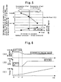
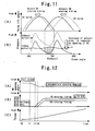
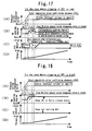
- the control represented by the one-dot chain line since, as a result of the VN opening degree being kept fully closed even after an intermediate period of acceleration in which the exhaust pressure pulsation becomes strong, turbo efficiency is degraded and the intake pressure cannot be sufficiently raised relative to the exhaust pressure; the scavenging effect becomes harder to achieve and the volumetric efficiency ⁇ v is degraded due to a blow-back of the exhaust gas to the intake side. For this reason, the control represented by the one-dot chain line also results in that the rise in the torque takes more time and the magnitude of the torque itself cannot be sufficiently raised relative to the control of the present embodiment.
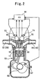
- the timing at which the trough of the exhaust pressure pulsation comes differs depending on conditions of the opening timing of the exhaust valve 68 and engine speed.
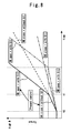
- an arrangement is made to change a ratio between the respective control amounts of the advance angle amount of the opening timing of the intake valve 64 and retard angle amount of the closing timing of the exhaust valve 68 when the valve overlap period is set after the VN 22c is operated. Further, an arrangement is made such that priorities of start timings of the advance angle control of the opening timing of the intake valve 64 and retard angle control of the closing timing of the exhaust valve 68 are determined in accordance with the phase at which the above-described trough comes.
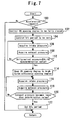
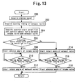
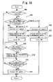
- step 210 it is determined whether or not the VN opening degree has reached a target intermediate opening degree during the current acceleration (step 210). As a result, if the determination is positive, it is judged that the situation in which the area where the intake pressure is higher than the exhaust pressure extends to the retard angle side of the exhaust top dead center has comes, and then the retard angle control of the closing timing of the exhaust valve 68 is also started (step 212). Note that the VN opening degree can be acquired by detecting a control amount of an actuator (not shown) driving the variable nozzle 22c.
- the control amount ratio of either of the advance angle control of the opening timing of the intake valve 64 and retard angle control of the closing timing of the exhaust valve 68 should be enhanced when setting the valve overlap period associated with the adjustment of the VN opening degree.
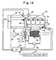
- Fig. 14 is a diagram for explaining the system configuration according to a third embodiment of the present invention. As regards the elements in Fig. 14 that are the same as those in Fig. 1 , their description is omitted or abridged with the same reference numerals assigned.
- the system of the present embodiment includes an exhaust volume changeover valve 80 in the connecting portion between the exhaust manifold 18 and the EGR passage 38.
- the exhaust volume changeover valve 80 is configured to be able to block the EGR passage 38 at the upstream side of the EGR cooler 40 (at the exhaust manifold 18 side).
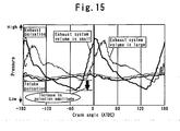
- the positive valve overlap period is set in such a way as to overlap with a timing at which the trough of the exhaust pressure pulsation comes. This makes it possible to effectively increase the torque of the diesel engine 10 by effectively utilizing the scavenging effect as shown in Fig. 17(D) .
- the valve overlap period By controlling the valve overlap period, the VN opening degree and the exhaust system volume in the order described so far, it becomes possible to successfully shorten a time needed for the rise in the torque of the diesel engine 10 during acceleration.
- valve overlap period is controlled so as to be zero if an acceleration request is detected. This makes it possible to sufficiently prevent the volumetric efficiency ⁇ v from degrading.
Landscapes
- Engineering & Computer Science (AREA)
- Chemical & Material Sciences (AREA)
- Combustion & Propulsion (AREA)
- Mechanical Engineering (AREA)
- General Engineering & Computer Science (AREA)
- Output Control And Ontrol Of Special Type Engine (AREA)
- Supercharger (AREA)
Claims (15)
- Appareil de commande pour un moteur à combustion interne, l'appareil comprenant :un mécanisme (66, 70) de soupape variable qui rend une période de chevauchement de soupapes variable, dans laquelle une période d'ouverture de soupape d'admission chevauche une période d'ouverture de soupape d'échappement;un moyen (50, 66, 70) de commande de période de chevauchement destiné à commander le mécanisme (66, 70) de soupape variable afin de commander la période de chevauchement de soupapes ;un turbocompresseur (22) qui comporte une turbine (22a) entraînée par une énergie d'échappement du moteur à combustion interne (10), et une buse variable (22c) destinée à régler un débit d'écoulement de gaz d'échappement fourni à la turbine (22a) ;un moyen (22c, 50) de commande de degré d'ouverture de buse destiné à commander un degré d'ouverture de la buse variable (22c) ; etun moyen (50) de détection de demande d'accélération destiné à détecter l'existence ou la non-existence d'une demande d'accélération, caractérisé en ce que l'appareil comprend en outre :un moyen (50) de jugement de pulsation de pression d'échappement destiné à juger si une pulsation de pression d'échappement est devenue suffisamment forte ou non en déterminant si une pression différentielle entre une pression d'échappement et une pression d'admission du moteur à combustion interne est devenue une valeur inférieure ou égale à une valeur de détermination prédéterminée ou non,dans lequel le moyen (22c, 50) de commande de degré d'ouverture de buse comporte un moyen (22c, 50) d'exécution de commande de fermeture de buse destiné à commander le degré d'ouverture de la buse variable (22c) de manière à ce qu'il soit égal à un premier degré d'ouverture prédéterminé, qui est sur un côté de fermeture par rapport au degré d'ouverture de la buse variable (22c) à un instant de détection où la demande d'accélération est détectée, pour une durée allant de l'instant de détection à un instant de jugement où la pulsation de pression d'échappement est jugée comme ayant été augmentée pendant une accélération,dans lequel le moyen (50, 66, 70) de commande de période de chevauchement comporte un moyen (50, 66, 70) de limitation de période de chevauchement destiné à commander la période de chevauchement de soupapes de façon à ce qu'elle soit plus courte que la période de chevauchement de soupapes à l'instant de détection, pour la durée allant de l'instant de détection à l'instant de jugement,dans lequel le moyen (22c, 50) de commande de degré d'ouverture de buse comporte en outre un moyen (22c, 50) d'exécution de commande d'ouverture de buse destiné à commander le degré d'ouverture de la buse variable (22c) pour qu'il soit égal à un deuxième degré d'ouverture prédéterminé qui est sur un côté d'ouverture par rapport au premier degré d'ouverture prédéterminé, après que l'instant de jugement est passé, etdans lequel le moyen (50, 66, 70) de commande de période de chevauchement comporte en outre un moyen (50, 66, 70) d'établissement de période de chevauchement destiné à établir la période de chevauchement de soupapes de façon à ce qu'elle chevauche un moment où un creux de la pulsation de pression d'échappement survient après que l'instant de jugement est passé.
- Appareil de commande pour le moteur à combustion interne selon la revendication 1,
dans lequel le moyen (50, 66, 70) de limitation de période de chevauchement limite la période de chevauchement de soupapes pour qu'elle soit égale à zéro ou sensiblement égale à zéro pour la durée allant de l'instant de détection à l'instant de jugement. - Appareil de commande pour le moteur à combustion interne selon la revendication 1 ou 2,
dans lequel le moyen (50, 66, 70) d'établissement de période de chevauchement établit la période de chevauchement de soupapes de manière à chevaucher le moment où le creux de la pulsation de pression d'échappement survient, après que le moyen (22c, 50) d'exécution de commande d'ouverture de buse commande le degré d'ouverture de la buse variable (22c) pour qu'il soit égal au deuxième degré d'ouverture prédéterminé. - Appareil de commande pour le moteur à combustion interne selon l'une quelconque des revendications 1 à 3,
dans lequel le moyen (50, 66, 70) d'établissement de période de chevauchement règle la période de chevauchement de soupapes qui est établie après que l'instant de jugement est passé, conformément à un changement dans le degré d'ouverture de la buse variable (22c) provoqué par le moyen (22c, 50) d'exécution de commande d'ouverture de buse. - Appareil de commande pour le moteur à combustion interne selon l'une quelconque des revendications 1 à 2,
dans lequel le moyen (22c, 50) de commande de degré d'ouverture de buse comporte en outre un moyen (22c, 50) d'établissement de degré d'ouverture à efficacité élevée destiné à, après que l'instant de jugement est passé, commander le degré d'ouverture de la buse variable (22c) pour qu'il soit égal à un degré d'ouverture à efficacité élevée où une efficacité de turbocompresseur du turbocompresseur (22) est supérieure à celle à l'instant de détection, et
dans lequel le moyen (50, 66, 70) de commande de période de chevauchement comporte en outre un moyen (50, 66, 70) d'établissement de période de chevauchement destiné à établir la période de chevauchement de soupapes de façon à chevaucher un moment où un creux de la pulsation de pression d'échappement survient, après que l'instant de jugement est passé. - Appareil de commande pour le moteur à combustion interne selon la revendication 5,
dans lequel le moyen (50, 66, 70) d'établissement de période de chevauchement établit la période de chevauchement de soupapes de façon à chevaucher le moment où le creux de la pulsation de pression d'échappement survient, après que le moyen (50, 66, 70) d'établissement de degré d'ouverture à haute efficacité commande le degré d'ouverture de la buse variable (22c) pour qu'il soit égal au degré d'ouverture à efficacité élevée. - Appareil de commande pour le moteur à combustion interne selon la revendication 5 ou 6,
dans lequel le moyen (50, 66, 70) d'établissement de période de chevauchement règle la période de chevauchement de soupapes qui est établie après que l'instant de jugement est passé, conformément à un changement dans le degré d'ouverture de la buse variable (22c) provoqué par le moyen (22c, 50) d'établissement de degré d'ouverture à haute efficacité. - Appareil de commande pour le moteur à combustion interne selon l'une quelconque des revendications 1 à 7,
dans lequel le mécanisme (66, 70) de soupape variable comporte un mécanisme (66) de soupape variable d'admission qui rend un moment d'ouverture d'une soupape d'admission (64) variable, et un mécanisme (70) de soupape variable d'échappement qui rend un moment de fermeture d'une soupape d'échappement (68) variable, et
dans lequel le moyen (50, 66, 70) d'établissement de période de chevauchement comporte en outre un moyen (50) d'établissement de rapport de quantité de commande destiné à, lorsque la période de chevauchement de soupapes est établie de manière à chevaucher le moment où le creux de la pulsation de pression d'échappement survient, après que l'instant de jugement est passé, établir un rapport entre des quantités de commande respectives d'une quantité d'angle d'avance du moment d'ouverture de la soupape d'admission (64) et d'une quantité d'angle de retard du moment de fermeture de la soupape d'échappement (68), sur la base d'une phase au niveau de laquelle le creux de la pulsation de pression d'échappement survient. - Appareil de commande pour le moteur à combustion interne selon l'une quelconque des revendications 1 à 8,
dans lequel le mécanisme (66, 70) de soupape variable comporte un mécanisme (66) de soupape variable d'admission qui rend un moment d'ouverture d'une soupape d'admission (64) variable, et un mécanisme (70) de soupape variable d'échappement qui rend un moment de fermeture d'une soupape d'échappement (68) variable, et
dans lequel le moyen (50, 66, 70) d'établissement de période de chevauchement comporte en outre un moyen (50) d'établissement d'ordre de début de commande destiné à, lorsque la période de chevauchement de soupapes est établie de manière à chevaucher le moment où le creux de la pulsation de pression d'échappement survient, après que l'instant de jugement est passé, établir un ordre de début d'une commande d'angle d'avance du moment d'ouverture de la soupape d'admission (64) et d'une commande d'angle de retard du moment de fermeture de la soupape d'échappement (68), sur la base d'une phase au niveau de laquelle le creux de la pulsation de pression d'échappement survient. - Appareil de commande pour le moteur à combustion interne selon l'une quelconque des revendications 1 à 9, l'appareil comprenant en outre :un moyen (50) d'acquisition d'informations d'intersection de pressions destiné à acquérir au moins un angle de vilebrequin d'un angle de vilebrequin au niveau d'une première intersection où une pression d'échappement croise une pression d'admission de sorte que la pression d'échappement se situe au-dessous de la pression d'admission à proximité d'un point mort haut d'échappement, et un angle de vilebrequin au niveau d'une deuxième intersection où la pression d'échappement croise la pression d'admission de sorte que la pression d'échappement dépasse la pression d'admission au niveau du point mort haut d'échappement,dans lequel le moyen (50, 66, 70) d'établissement de période de chevauchement de soupapes comporte en outre un moyen (50, 66, 70) de réglage de moment d'ouverture/fermeture de soupape destiné à commander le moment d'ouverture de la soupape d' admission (64) et/ou le moment de fermeture de la soupape d'échappement (68) de sorte que le moment d'ouverture de la soupape d'admission (64) devienne l'angle de vilebrequin au niveau de la première intersection et/ou de sorte que le moment de fermeture de la soupape d'échappement (68) devienne l'angle de vilebrequin au niveau de la deuxième intersection.
- Appareil de commande pour le moteur à combustion interne selon l'une quelconque des revendications 1 à 2, l'appareil comprenant en outre :un moyen (84) de détermination d'engorgement destiné à déterminer un degré d'engorgement d'un appareil (24) de purification de gaz d'échappement disposé dans un passage d'échappement (20) ; etun moyen (84) de modification de commande destiné à, conformément au degré d'engorgement de l'appareil (24) de purification de gaz d'échappement déterminé par le moyen (84) de détermination d'engorgement, modifier une commande de degré d'ouverture de la buse variable (22c) et une commande de la période de chevauchement de soupapes après que l'instant de jugement est passé.
- Appareil de commande pour le moteur à combustion interne selon la revendication 11,
dans lequel le moyen (84) de modification de commande comporte
un moyen (84) d'exécution de commande d'ouverture de buse en cas de faible engorgement destiné à, si le moyen (84) de détermination d'engorgement détermine que le degré d'engorgement de l'appareil (24) de purification de gaz d'échappement est faible, commander le degré d'ouverture de la buse variable (22c) pour qu'il soit égal à un deuxième degré d'ouverture prédéterminé qui est sur un côté d'ouverture par rapport au premier degré d'ouverture prédéterminé après que l'instant de jugement est passé, et
un moyen (66, 70, 84) d'établissement de période de chevauchement en cas de faible engorgement destiné à, si le moyen (84) de détermination d'engorgement détermine que le degré d'engorgement de l'appareil (24) de purification de gaz d'échappement est faible, établir la période de chevauchement de soupapes de façon à chevaucher un moment où un creux de la pulsation de pression d'échappement survient, après que l'instant de jugement est passé. - Appareil de commande pour le moteur à combustion interne selon la revendication 11 ou 12, l'appareil comprenant en outre :un moyen (80, 84) de variation de volume de système d'échappement qui rend un volume de système d'échappement variable qui est un volume obtenu en tant que somme d'un volume de collecteur d'échappement et d'un espace en communication avec celui-ci,dans lequel, si le moyen (84) de détermination d'engorgement détermine que le degré d'engorgement de l'appareil (24) de purification de gaz d'échappement est faible, le moyen (80, 84) de variation de volume de système d'échappement réduit le volume de système d'échappement après que l'instant de jugement est passé.
- Appareil de commande pour le moteur à combustion interne selon la revendication 11,
dans lequel la demande d'augmenter une pulsation de pression d'échappement est une demande d'accélération, et
dans lequel le moyen (84) de modification de commande comporte un moyen (84) de commande en cas d'engorgement élevé destiné à commander le degré d'ouverture de la buse variable (22c) et la période de chevauchement de soupapes de sorte que la commande du degré d'ouverture de buse variable et d'une période de chevauchement de soupapes soit maintenue en exécution pendant une accélération, si le moyen (84) de détermination d'engorgement détermine que le degré d'engorgement de l'appareil (24) de purification de gaz d'échappement est élevé. - Appareil de commande pour le moteur à combustion interne selon la revendication 14, l'appareil comprenant en outre :un moyen (80, 84) de variation de volume de système d'échappement qui rend un volume de système d'échappement variable qui est un volume obtenu en tant que somme d'un volume de collecteur d'échappement et d'un espace en communication avec celui-cidans lequel, si le moyen (84) de détermination d'engorgement détermine que le degré d'engorgement de l'appareil (24) de purification de gaz d'échappement est élevé, le moyen (84) de variation de volume de système d'échappement réduit le volume de système d'échappement après que l'instant de jugement est passé.
Applications Claiming Priority (3)
| Application Number | Priority Date | Filing Date | Title |
|---|---|---|---|
| JP2007294655 | 2007-11-13 | ||
| JP2008172550A JP4900333B2 (ja) | 2007-11-13 | 2008-07-01 | 内燃機関の制御装置 |
| PCT/JP2008/070426 WO2009063831A1 (fr) | 2007-11-13 | 2008-11-10 | Dispositif de commande de moteur à combustion interne |
Publications (3)
| Publication Number | Publication Date |
|---|---|
| EP2208877A1 EP2208877A1 (fr) | 2010-07-21 |
| EP2208877A4 EP2208877A4 (fr) | 2012-11-21 |
| EP2208877B1 true EP2208877B1 (fr) | 2014-05-21 |
Family
ID=40638680
Family Applications (1)
| Application Number | Title | Priority Date | Filing Date |
|---|---|---|---|
| EP08849001.6A Not-in-force EP2208877B1 (fr) | 2007-11-13 | 2008-11-10 | Dispositif de commande de moteur à combustion interne |
Country Status (4)
| Country | Link |
|---|---|
| US (1) | US8220263B2 (fr) |
| EP (1) | EP2208877B1 (fr) |
| JP (1) | JP4900333B2 (fr) |
| WO (1) | WO2009063831A1 (fr) |
Families Citing this family (22)
| Publication number | Priority date | Publication date | Assignee | Title |
|---|---|---|---|---|
| EP2347110B1 (fr) * | 2008-11-20 | 2015-09-16 | Wärtsilä Finland Oy | Procédé de commande de vitesse de turbocompresseur de moteur à pistons et système de commande d'un moteur à pistons turbocompressé |
| US8099228B2 (en) * | 2008-12-26 | 2012-01-17 | Toyota Jidosha Kabushiki Kaisha | Control apparatus for internal combustion engine |
| JP5206565B2 (ja) * | 2009-04-15 | 2013-06-12 | トヨタ自動車株式会社 | 内燃機関の制御システム |
| JP5454071B2 (ja) * | 2009-10-16 | 2014-03-26 | トヨタ自動車株式会社 | 内燃機関の排気脈動特性推定装置及び制御システム |
| WO2011083577A1 (fr) * | 2010-01-07 | 2011-07-14 | トヨタ自動車株式会社 | Dispositif de commande pour moteur à combustion interne |
| DE102010018659A1 (de) * | 2010-04-28 | 2011-11-03 | J. Eberspächer GmbH & Co. KG | Kolbenmotor, Verfahren und Verwendung |
| EP2642102B1 (fr) * | 2010-11-19 | 2018-08-22 | Toyota Jidosha Kabushiki Kaisha | Dispositif de commande pour moteur à combustion interne |
| WO2012070148A1 (fr) | 2010-11-26 | 2012-05-31 | トヨタ自動車株式会社 | Dispositif de commande pour moteur à combustion interne |
| JP5772025B2 (ja) * | 2011-02-07 | 2015-09-02 | 日産自動車株式会社 | 内燃機関の制御装置 |
| DE102011081150A1 (de) * | 2011-08-17 | 2013-02-21 | Robert Bosch Gmbh | Verfahren und Vorrichtung zum Betreiben eines Verbrennungsmotors |
| DE102011114065A1 (de) * | 2011-09-22 | 2013-03-28 | Daimler Ag | Verfahren zum Betreiben einer Brennkraftmaschine |
| DE102012014713A1 (de) * | 2012-07-25 | 2014-01-30 | Volkswagen Aktiengesellschaft | Verfahren zum Betreiben eines Verbrennungsmotors |
| JP5379918B1 (ja) * | 2013-01-11 | 2013-12-25 | 三菱電機株式会社 | 内燃機関の制御装置 |
| JP6020250B2 (ja) * | 2013-02-22 | 2016-11-02 | マツダ株式会社 | ターボ過給機付き火花点火式エンジン |
| ITBO20130618A1 (it) | 2013-11-12 | 2015-05-13 | Magneti Marelli Spa | Metodo di controllo di una valvola wastegate in un motore a combustione interna turbocompresso |
| JP5935817B2 (ja) * | 2014-01-17 | 2016-06-15 | 株式会社デンソー | 内燃機関の過給制御装置 |
| KR101766076B1 (ko) | 2015-12-08 | 2017-08-07 | 현대자동차주식회사 | 내연기관의 제어 장치 및 제어 방법 |
| SE542390C2 (en) * | 2016-10-19 | 2020-04-21 | Scania Cv Ab | Method and system for controlling the intake and exhaust valves in an internal combustion engine |
| SE541558C2 (en) * | 2016-10-19 | 2019-10-29 | Scania Cv Ab | Method and system for controlling the intake and exhaust valves in an internal combustion engine |
| CN111720224B (zh) * | 2019-03-18 | 2022-08-02 | 上海汽车集团股份有限公司 | 一种充气效率的修正方法、系统 |
| JP7207236B2 (ja) * | 2019-08-28 | 2023-01-18 | トヨタ自動車株式会社 | エンジン装置 |
| SE543456C2 (en) * | 2019-10-23 | 2021-02-23 | Scania Cv Ab | Four-Stroke Internal Combustion Engine and Method of Controlling Timings of an Exhaust Camshaft and an Intake Camshaft |
Family Cites Families (32)
| Publication number | Priority date | Publication date | Assignee | Title |
|---|---|---|---|---|
| JP2666142B2 (ja) | 1987-02-04 | 1997-10-22 | 旭光学工業株式会社 | カメラの自動焦点検出装置 |
| JPS6437982A (en) | 1987-08-05 | 1989-02-08 | Marusuzu Kk | Pinball replenishment monitor apparatus |
| JPH02176114A (ja) * | 1988-12-27 | 1990-07-09 | Honda Motor Co Ltd | エンジンの制御装置 |
| JP3281068B2 (ja) * | 1992-12-14 | 2002-05-13 | マツダ株式会社 | 機械式過給機付エンジンのバルブタイミング可変装置 |
| FR2712922B1 (fr) | 1993-11-22 | 1996-01-05 | Remi Curtil | Procédé pour améliorer le fonctionnement d'un moteur thermique suralimenté et balayé avec de l'air, et moteur thermique agencé pour la mise en Óoeuvre du procédé. |
| JP3678861B2 (ja) | 1996-12-18 | 2005-08-03 | ヤマハ発動機株式会社 | エンジンの運転制御装置 |
| JP3932600B2 (ja) * | 1997-05-21 | 2007-06-20 | 日産自動車株式会社 | ターボ過給機付き内燃機関の動弁制御システム |
| JPH1122499A (ja) | 1997-07-03 | 1999-01-26 | Toyota Motor Corp | 内燃機関のバルブタイミング制御装置 |
| JP3937522B2 (ja) * | 1997-09-08 | 2007-06-27 | 日産自動車株式会社 | 内燃機関の可変動弁装置 |
| JP3757579B2 (ja) * | 1997-11-10 | 2006-03-22 | 日産自動車株式会社 | 過給機付内燃機関の過給圧制御装置 |
| JP2001003757A (ja) * | 1999-06-16 | 2001-01-09 | Isuzu Motors Ltd | 過給機付きエンジン |
| JP2003003871A (ja) * | 2001-06-20 | 2003-01-08 | Hitachi Unisia Automotive Ltd | 過給機付内燃機関の可変動弁装置 |
| JP2003097252A (ja) * | 2001-09-25 | 2003-04-03 | Komatsu Ltd | 内燃機関の排気ガス浄化装置 |
| US6772742B2 (en) * | 2002-03-01 | 2004-08-10 | International Engine Intellectual Property Company, Llc | Method and apparatus for flexibly regulating internal combustion engine valve flow |
| JP4385585B2 (ja) | 2002-10-18 | 2009-12-16 | トヨタ自動車株式会社 | 内燃機関 |
| JP4066796B2 (ja) * | 2002-12-09 | 2008-03-26 | 三菱自動車エンジニアリング株式会社 | 可変バルブタイミング機構付内燃機関 |
| JP4165210B2 (ja) | 2002-12-25 | 2008-10-15 | トヨタ自動車株式会社 | エンジン制御装置およびその方法 |
| JP2005083281A (ja) * | 2003-09-09 | 2005-03-31 | Toyota Motor Corp | 内燃機関の制御装置 |
| JP2006046084A (ja) * | 2004-07-30 | 2006-02-16 | Toyota Motor Corp | 内燃機関の点火時期制御装置 |
| JP4479469B2 (ja) * | 2004-11-04 | 2010-06-09 | トヨタ自動車株式会社 | 過給機付内燃機関 |
| US7461504B2 (en) * | 2004-12-21 | 2008-12-09 | Detroit Diesel Corporation | Method and system for controlling temperatures of exhaust gases emitted from internal combustion engine to facilitate regeneration of a particulate filter |
| DE102005002246A1 (de) | 2005-01-18 | 2006-07-20 | Daimlerchrysler Ag | Brennkraftmaschine mit einer Abgasrückführungseinrichtung und Verfahren zum Betrieb einer Brennkraftmaschine |
| JP4475221B2 (ja) * | 2005-03-11 | 2010-06-09 | トヨタ自動車株式会社 | エンジン |
| JP2007100607A (ja) | 2005-10-05 | 2007-04-19 | Toyota Motor Corp | 内燃機関の始動制御装置 |
| US7487750B2 (en) * | 2005-11-29 | 2009-02-10 | Ford Global Technologies, Llc | Variable intake valve and exhaust valve timing strategy for improving performance in a hydrogen fueled engine |
| JP4650321B2 (ja) * | 2006-03-28 | 2011-03-16 | トヨタ自動車株式会社 | 制御装置 |
| US7458346B2 (en) * | 2006-04-05 | 2008-12-02 | Ford Global Technologies, Llc | Method for controlling valves of an engine having a variable event valvetrain during an engine stop |
| JP2008008226A (ja) | 2006-06-29 | 2008-01-17 | Toyota Motor Corp | 内燃機関の制御装置 |
| JP2008019835A (ja) * | 2006-07-14 | 2008-01-31 | Mazda Motor Corp | 過給機付きエンジン |
| JP4804384B2 (ja) | 2007-03-08 | 2011-11-02 | 日立オートモティブシステムズ株式会社 | 内燃機関の可変動弁装置及び制御装置 |
| JP4823948B2 (ja) * | 2007-03-23 | 2011-11-24 | 富士重工業株式会社 | エンジンの制御装置 |
| US7921944B2 (en) * | 2007-10-29 | 2011-04-12 | Ford Global Technologies, Llc | Compression system for internal combustion engine including a rotationally uncoupled exhaust gas turbine |
-
2008
- 2008-07-01 JP JP2008172550A patent/JP4900333B2/ja not_active Expired - Fee Related
- 2008-11-10 EP EP08849001.6A patent/EP2208877B1/fr not_active Not-in-force
- 2008-11-10 WO PCT/JP2008/070426 patent/WO2009063831A1/fr active Application Filing
- 2008-11-10 US US12/682,838 patent/US8220263B2/en active Active
Also Published As
| Publication number | Publication date |
|---|---|
| JP2009138733A (ja) | 2009-06-25 |
| US8220263B2 (en) | 2012-07-17 |
| WO2009063831A1 (fr) | 2009-05-22 |
| EP2208877A4 (fr) | 2012-11-21 |
| JP4900333B2 (ja) | 2012-03-21 |
| EP2208877A1 (fr) | 2010-07-21 |
| US20100242471A1 (en) | 2010-09-30 |
Similar Documents
| Publication | Publication Date | Title |
|---|---|---|
| EP2208877B1 (fr) | Dispositif de commande de moteur à combustion interne | |
| EP2397673B1 (fr) | Dispositif de commande de moteur a combustion interne | |
| US8201406B2 (en) | Control apparatus for internal combustion engine | |
| EP2372131B1 (fr) | Dispositif de commande pour moteur a combustion interne | |
| JP6011477B2 (ja) | エンジンの制御装置 | |
| JP6015575B2 (ja) | エンジンの制御装置 | |
| JP6111899B2 (ja) | エンジンの制御装置 | |
| JP2009103084A (ja) | 内燃機関の制御装置 | |
| JP2018184837A (ja) | 内燃機関の制御装置 | |
| US20100076668A1 (en) | Control apparatus for internal combustion engine | |
| CN109555616B (zh) | 发动机的控制设备 | |
| JP2009299623A (ja) | 内燃機関の制御装置 | |
| EP2584178B1 (fr) | Dispositif de commande pour moteur à combustion interne | |
| JP2009068450A (ja) | 内燃機関の制御装置 | |
| JP2009209848A (ja) | 内燃機関およびその制御装置 | |
| JPWO2011141999A1 (ja) | 内燃機関の制御装置 | |
| JP2009162108A (ja) | 内燃機関の制御装置 |
Legal Events
| Date | Code | Title | Description |
|---|---|---|---|
| PUAI | Public reference made under article 153(3) epc to a published international application that has entered the european phase |
Free format text: ORIGINAL CODE: 0009012 |
|
| 17P | Request for examination filed |
Effective date: 20100413 |
|
| AK | Designated contracting states |
Kind code of ref document: A1 Designated state(s): AT BE BG CH CY CZ DE DK EE ES FI FR GB GR HR HU IE IS IT LI LT LU LV MC MT NL NO PL PT RO SE SI SK TR |
|
| AX | Request for extension of the european patent |
Extension state: AL BA MK RS |
|
| DAX | Request for extension of the european patent (deleted) | ||
| A4 | Supplementary search report drawn up and despatched |
Effective date: 20121023 |
|
| RIC1 | Information provided on ipc code assigned before grant |
Ipc: F02D 15/04 20060101ALN20121017BHEP Ipc: F02D 13/02 20060101AFI20121017BHEP Ipc: F02D 41/10 20060101ALN20121017BHEP Ipc: F02D 23/00 20060101ALI20121017BHEP Ipc: F02D 41/00 20060101ALI20121017BHEP |
|
| RAP1 | Party data changed (applicant data changed or rights of an application transferred) |
Owner name: TOYOTA JIDOSHA KABUSHIKI KAISHA |
|
| RIC1 | Information provided on ipc code assigned before grant |
Ipc: F02D 15/04 20060101ALN20131118BHEP Ipc: F02D 41/10 20060101ALN20131118BHEP Ipc: F02D 13/02 20060101AFI20131118BHEP Ipc: F02D 23/00 20060101ALI20131118BHEP Ipc: F02D 41/00 20060101ALI20131118BHEP |
|
| GRAP | Despatch of communication of intention to grant a patent |
Free format text: ORIGINAL CODE: EPIDOSNIGR1 |
|
| INTG | Intention to grant announced |
Effective date: 20140121 |
|
| RIN1 | Information on inventor provided before grant (corrected) |
Inventor name: ISHIYAMA, SHINOBU Inventor name: KOGO, TOMOYUKI Inventor name: ONO, TOMOYUKI Inventor name: ITO, KATSUHIRO Inventor name: TOMODA, TERUTOSHI Inventor name: NAKATANI, KOICHIRO |
|
| GRAS | Grant fee paid |
Free format text: ORIGINAL CODE: EPIDOSNIGR3 |
|
| GRAA | (expected) grant |
Free format text: ORIGINAL CODE: 0009210 |
|
| AK | Designated contracting states |
Kind code of ref document: B1 Designated state(s): AT BE BG CH CY CZ DE DK EE ES FI FR GB GR HR HU IE IS IT LI LT LU LV MC MT NL NO PL PT RO SE SI SK TR |
|
| REG | Reference to a national code |
Ref country code: GB Ref legal event code: FG4D |
|
| REG | Reference to a national code |
Ref country code: CH Ref legal event code: EP |
|
| REG | Reference to a national code |
Ref country code: AT Ref legal event code: REF Ref document number: 669729 Country of ref document: AT Kind code of ref document: T Effective date: 20140615 |
|
| REG | Reference to a national code |
Ref country code: IE Ref legal event code: FG4D |
|
| REG | Reference to a national code |
Ref country code: DE Ref legal event code: R096 Ref document number: 602008032456 Country of ref document: DE Effective date: 20140703 |
|
| REG | Reference to a national code |
Ref country code: DE Ref legal event code: R084 Ref document number: 602008032456 Country of ref document: DE |
|
| REG | Reference to a national code |
Ref country code: NL Ref legal event code: VDEP Effective date: 20140521 Ref country code: AT Ref legal event code: MK05 Ref document number: 669729 Country of ref document: AT Kind code of ref document: T Effective date: 20140521 |
|
| REG | Reference to a national code |
Ref country code: DE Ref legal event code: R084 Ref document number: 602008032456 Country of ref document: DE Effective date: 20140910 |
|
| REG | Reference to a national code |
Ref country code: LT Ref legal event code: MG4D |
|
| PG25 | Lapsed in a contracting state [announced via postgrant information from national office to epo] |
Ref country code: IS Free format text: LAPSE BECAUSE OF FAILURE TO SUBMIT A TRANSLATION OF THE DESCRIPTION OR TO PAY THE FEE WITHIN THE PRESCRIBED TIME-LIMIT Effective date: 20140921 Ref country code: GR Free format text: LAPSE BECAUSE OF FAILURE TO SUBMIT A TRANSLATION OF THE DESCRIPTION OR TO PAY THE FEE WITHIN THE PRESCRIBED TIME-LIMIT Effective date: 20140822 Ref country code: FI Free format text: LAPSE BECAUSE OF FAILURE TO SUBMIT A TRANSLATION OF THE DESCRIPTION OR TO PAY THE FEE WITHIN THE PRESCRIBED TIME-LIMIT Effective date: 20140521 Ref country code: LT Free format text: LAPSE BECAUSE OF FAILURE TO SUBMIT A TRANSLATION OF THE DESCRIPTION OR TO PAY THE FEE WITHIN THE PRESCRIBED TIME-LIMIT Effective date: 20140521 Ref country code: NO Free format text: LAPSE BECAUSE OF FAILURE TO SUBMIT A TRANSLATION OF THE DESCRIPTION OR TO PAY THE FEE WITHIN THE PRESCRIBED TIME-LIMIT Effective date: 20140821 |
|
| PG25 | Lapsed in a contracting state [announced via postgrant information from national office to epo] |
Ref country code: HR Free format text: LAPSE BECAUSE OF FAILURE TO SUBMIT A TRANSLATION OF THE DESCRIPTION OR TO PAY THE FEE WITHIN THE PRESCRIBED TIME-LIMIT Effective date: 20140521 Ref country code: ES Free format text: LAPSE BECAUSE OF FAILURE TO SUBMIT A TRANSLATION OF THE DESCRIPTION OR TO PAY THE FEE WITHIN THE PRESCRIBED TIME-LIMIT Effective date: 20140521 Ref country code: AT Free format text: LAPSE BECAUSE OF FAILURE TO SUBMIT A TRANSLATION OF THE DESCRIPTION OR TO PAY THE FEE WITHIN THE PRESCRIBED TIME-LIMIT Effective date: 20140521 Ref country code: SE Free format text: LAPSE BECAUSE OF FAILURE TO SUBMIT A TRANSLATION OF THE DESCRIPTION OR TO PAY THE FEE WITHIN THE PRESCRIBED TIME-LIMIT Effective date: 20140521 Ref country code: PL Free format text: LAPSE BECAUSE OF FAILURE TO SUBMIT A TRANSLATION OF THE DESCRIPTION OR TO PAY THE FEE WITHIN THE PRESCRIBED TIME-LIMIT Effective date: 20140521 Ref country code: LV Free format text: LAPSE BECAUSE OF FAILURE TO SUBMIT A TRANSLATION OF THE DESCRIPTION OR TO PAY THE FEE WITHIN THE PRESCRIBED TIME-LIMIT Effective date: 20140521 |
|
| PG25 | Lapsed in a contracting state [announced via postgrant information from national office to epo] |
Ref country code: PT Free format text: LAPSE BECAUSE OF FAILURE TO SUBMIT A TRANSLATION OF THE DESCRIPTION OR TO PAY THE FEE WITHIN THE PRESCRIBED TIME-LIMIT Effective date: 20140922 |
|
| PG25 | Lapsed in a contracting state [announced via postgrant information from national office to epo] |
Ref country code: SK Free format text: LAPSE BECAUSE OF FAILURE TO SUBMIT A TRANSLATION OF THE DESCRIPTION OR TO PAY THE FEE WITHIN THE PRESCRIBED TIME-LIMIT Effective date: 20140521 Ref country code: RO Free format text: LAPSE BECAUSE OF FAILURE TO SUBMIT A TRANSLATION OF THE DESCRIPTION OR TO PAY THE FEE WITHIN THE PRESCRIBED TIME-LIMIT Effective date: 20140521 Ref country code: CZ Free format text: LAPSE BECAUSE OF FAILURE TO SUBMIT A TRANSLATION OF THE DESCRIPTION OR TO PAY THE FEE WITHIN THE PRESCRIBED TIME-LIMIT Effective date: 20140521 Ref country code: BE Free format text: LAPSE BECAUSE OF FAILURE TO SUBMIT A TRANSLATION OF THE DESCRIPTION OR TO PAY THE FEE WITHIN THE PRESCRIBED TIME-LIMIT Effective date: 20140521 Ref country code: DK Free format text: LAPSE BECAUSE OF FAILURE TO SUBMIT A TRANSLATION OF THE DESCRIPTION OR TO PAY THE FEE WITHIN THE PRESCRIBED TIME-LIMIT Effective date: 20140521 Ref country code: EE Free format text: LAPSE BECAUSE OF FAILURE TO SUBMIT A TRANSLATION OF THE DESCRIPTION OR TO PAY THE FEE WITHIN THE PRESCRIBED TIME-LIMIT Effective date: 20140521 |
|
| REG | Reference to a national code |
Ref country code: DE Ref legal event code: R097 Ref document number: 602008032456 Country of ref document: DE |
|
| PG25 | Lapsed in a contracting state [announced via postgrant information from national office to epo] |
Ref country code: NL Free format text: LAPSE BECAUSE OF FAILURE TO SUBMIT A TRANSLATION OF THE DESCRIPTION OR TO PAY THE FEE WITHIN THE PRESCRIBED TIME-LIMIT Effective date: 20140521 |
|
| PLBE | No opposition filed within time limit |
Free format text: ORIGINAL CODE: 0009261 |
|
| STAA | Information on the status of an ep patent application or granted ep patent |
Free format text: STATUS: NO OPPOSITION FILED WITHIN TIME LIMIT |
|
| 26N | No opposition filed |
Effective date: 20150224 |
|
| PG25 | Lapsed in a contracting state [announced via postgrant information from national office to epo] |
Ref country code: IT Free format text: LAPSE BECAUSE OF FAILURE TO SUBMIT A TRANSLATION OF THE DESCRIPTION OR TO PAY THE FEE WITHIN THE PRESCRIBED TIME-LIMIT Effective date: 20140521 |
|
| REG | Reference to a national code |
Ref country code: DE Ref legal event code: R097 Ref document number: 602008032456 Country of ref document: DE Effective date: 20150224 |
|
| PG25 | Lapsed in a contracting state [announced via postgrant information from national office to epo] |
Ref country code: MC Free format text: LAPSE BECAUSE OF FAILURE TO SUBMIT A TRANSLATION OF THE DESCRIPTION OR TO PAY THE FEE WITHIN THE PRESCRIBED TIME-LIMIT Effective date: 20140521 Ref country code: LU Free format text: LAPSE BECAUSE OF FAILURE TO SUBMIT A TRANSLATION OF THE DESCRIPTION OR TO PAY THE FEE WITHIN THE PRESCRIBED TIME-LIMIT Effective date: 20141110 |
|
| REG | Reference to a national code |
Ref country code: CH Ref legal event code: PL |
|
| GBPC | Gb: european patent ceased through non-payment of renewal fee |
Effective date: 20141110 |
|
| PG25 | Lapsed in a contracting state [announced via postgrant information from national office to epo] |
Ref country code: CH Free format text: LAPSE BECAUSE OF NON-PAYMENT OF DUE FEES Effective date: 20141130 Ref country code: LI Free format text: LAPSE BECAUSE OF NON-PAYMENT OF DUE FEES Effective date: 20141130 Ref country code: SI Free format text: LAPSE BECAUSE OF FAILURE TO SUBMIT A TRANSLATION OF THE DESCRIPTION OR TO PAY THE FEE WITHIN THE PRESCRIBED TIME-LIMIT Effective date: 20140521 |
|
| REG | Reference to a national code |
Ref country code: IE Ref legal event code: MM4A |
|
| REG | Reference to a national code |
Ref country code: FR Ref legal event code: ST Effective date: 20150731 |
|
| PG25 | Lapsed in a contracting state [announced via postgrant information from national office to epo] |
Ref country code: GB Free format text: LAPSE BECAUSE OF NON-PAYMENT OF DUE FEES Effective date: 20141110 Ref country code: IE Free format text: LAPSE BECAUSE OF NON-PAYMENT OF DUE FEES Effective date: 20141110 |
|
| PG25 | Lapsed in a contracting state [announced via postgrant information from national office to epo] |
Ref country code: FR Free format text: LAPSE BECAUSE OF NON-PAYMENT OF DUE FEES Effective date: 20141201 |
|
| PG25 | Lapsed in a contracting state [announced via postgrant information from national office to epo] |
Ref country code: BG Free format text: LAPSE BECAUSE OF FAILURE TO SUBMIT A TRANSLATION OF THE DESCRIPTION OR TO PAY THE FEE WITHIN THE PRESCRIBED TIME-LIMIT Effective date: 20140521 |
|
| PG25 | Lapsed in a contracting state [announced via postgrant information from national office to epo] |
Ref country code: CY Free format text: LAPSE BECAUSE OF FAILURE TO SUBMIT A TRANSLATION OF THE DESCRIPTION OR TO PAY THE FEE WITHIN THE PRESCRIBED TIME-LIMIT Effective date: 20140521 |
|
| PG25 | Lapsed in a contracting state [announced via postgrant information from national office to epo] |
Ref country code: TR Free format text: LAPSE BECAUSE OF FAILURE TO SUBMIT A TRANSLATION OF THE DESCRIPTION OR TO PAY THE FEE WITHIN THE PRESCRIBED TIME-LIMIT Effective date: 20140521 Ref country code: HU Free format text: LAPSE BECAUSE OF FAILURE TO SUBMIT A TRANSLATION OF THE DESCRIPTION OR TO PAY THE FEE WITHIN THE PRESCRIBED TIME-LIMIT; INVALID AB INITIO Effective date: 20081110 Ref country code: MT Free format text: LAPSE BECAUSE OF FAILURE TO SUBMIT A TRANSLATION OF THE DESCRIPTION OR TO PAY THE FEE WITHIN THE PRESCRIBED TIME-LIMIT Effective date: 20140521 |
|
| PGFP | Annual fee paid to national office [announced via postgrant information from national office to epo] |
Ref country code: DE Payment date: 20210929 Year of fee payment: 14 |
|
| REG | Reference to a national code |
Ref country code: DE Ref legal event code: R119 Ref document number: 602008032456 Country of ref document: DE |
|
| PG25 | Lapsed in a contracting state [announced via postgrant information from national office to epo] |
Ref country code: DE Free format text: LAPSE BECAUSE OF NON-PAYMENT OF DUE FEES Effective date: 20230601 |