EP2204621B1 - Climatiseur et procédé de détection de dysfonctionnements correspondant - Google Patents
Climatiseur et procédé de détection de dysfonctionnements correspondant Download PDFInfo
- Publication number
- EP2204621B1 EP2204621B1 EP10000069.4A EP10000069A EP2204621B1 EP 2204621 B1 EP2204621 B1 EP 2204621B1 EP 10000069 A EP10000069 A EP 10000069A EP 2204621 B1 EP2204621 B1 EP 2204621B1
- Authority
- EP
- European Patent Office
- Prior art keywords
- indoor
- expansion valve
- temperature
- indoor expansion
- pipe temperature
- Prior art date
- Legal status (The legal status is an assumption and is not a legal conclusion. Google has not performed a legal analysis and makes no representation as to the accuracy of the status listed.)
- Active
Links
Images


Classifications
-
- F—MECHANICAL ENGINEERING; LIGHTING; HEATING; WEAPONS; BLASTING
- F24—HEATING; RANGES; VENTILATING
- F24F—AIR-CONDITIONING; AIR-HUMIDIFICATION; VENTILATION; USE OF AIR CURRENTS FOR SCREENING
- F24F11/00—Control or safety arrangements
- F24F11/30—Control or safety arrangements for purposes related to the operation of the system, e.g. for safety or monitoring
- F24F11/32—Responding to malfunctions or emergencies
- F24F11/38—Failure diagnosis
-
- F—MECHANICAL ENGINEERING; LIGHTING; HEATING; WEAPONS; BLASTING
- F24—HEATING; RANGES; VENTILATING
- F24F—AIR-CONDITIONING; AIR-HUMIDIFICATION; VENTILATION; USE OF AIR CURRENTS FOR SCREENING
- F24F11/00—Control or safety arrangements
- F24F11/50—Control or safety arrangements characterised by user interfaces or communication
- F24F11/52—Indication arrangements, e.g. displays
- F24F11/526—Indication arrangements, e.g. displays giving audible indications
-
- F—MECHANICAL ENGINEERING; LIGHTING; HEATING; WEAPONS; BLASTING
- F24—HEATING; RANGES; VENTILATING
- F24F—AIR-CONDITIONING; AIR-HUMIDIFICATION; VENTILATION; USE OF AIR CURRENTS FOR SCREENING
- F24F11/00—Control or safety arrangements
- F24F11/70—Control systems characterised by their outputs; Constructional details thereof
- F24F11/80—Control systems characterised by their outputs; Constructional details thereof for controlling the temperature of the supplied air
- F24F11/83—Control systems characterised by their outputs; Constructional details thereof for controlling the temperature of the supplied air by controlling the supply of heat-exchange fluids to heat-exchangers
- F24F11/84—Control systems characterised by their outputs; Constructional details thereof for controlling the temperature of the supplied air by controlling the supply of heat-exchange fluids to heat-exchangers using valves
-
- F—MECHANICAL ENGINEERING; LIGHTING; HEATING; WEAPONS; BLASTING
- F25—REFRIGERATION OR COOLING; COMBINED HEATING AND REFRIGERATION SYSTEMS; HEAT PUMP SYSTEMS; MANUFACTURE OR STORAGE OF ICE; LIQUEFACTION SOLIDIFICATION OF GASES
- F25B—REFRIGERATION MACHINES, PLANTS OR SYSTEMS; COMBINED HEATING AND REFRIGERATION SYSTEMS; HEAT PUMP SYSTEMS
- F25B49/00—Arrangement or mounting of control or safety devices
- F25B49/005—Arrangement or mounting of control or safety devices of safety devices
-
- F—MECHANICAL ENGINEERING; LIGHTING; HEATING; WEAPONS; BLASTING
- F24—HEATING; RANGES; VENTILATING
- F24F—AIR-CONDITIONING; AIR-HUMIDIFICATION; VENTILATION; USE OF AIR CURRENTS FOR SCREENING
- F24F11/00—Control or safety arrangements
- F24F11/30—Control or safety arrangements for purposes related to the operation of the system, e.g. for safety or monitoring
- F24F11/32—Responding to malfunctions or emergencies
-
- F—MECHANICAL ENGINEERING; LIGHTING; HEATING; WEAPONS; BLASTING
- F24—HEATING; RANGES; VENTILATING
- F24F—AIR-CONDITIONING; AIR-HUMIDIFICATION; VENTILATION; USE OF AIR CURRENTS FOR SCREENING
- F24F2140/00—Control inputs relating to system states
-
- F—MECHANICAL ENGINEERING; LIGHTING; HEATING; WEAPONS; BLASTING
- F24—HEATING; RANGES; VENTILATING
- F24F—AIR-CONDITIONING; AIR-HUMIDIFICATION; VENTILATION; USE OF AIR CURRENTS FOR SCREENING
- F24F2140/00—Control inputs relating to system states
- F24F2140/20—Heat-exchange fluid temperature
-
- F—MECHANICAL ENGINEERING; LIGHTING; HEATING; WEAPONS; BLASTING
- F25—REFRIGERATION OR COOLING; COMBINED HEATING AND REFRIGERATION SYSTEMS; HEAT PUMP SYSTEMS; MANUFACTURE OR STORAGE OF ICE; LIQUEFACTION SOLIDIFICATION OF GASES
- F25B—REFRIGERATION MACHINES, PLANTS OR SYSTEMS; COMBINED HEATING AND REFRIGERATION SYSTEMS; HEAT PUMP SYSTEMS
- F25B2313/00—Compression machines, plants or systems with reversible cycle not otherwise provided for
- F25B2313/031—Sensor arrangements
- F25B2313/0314—Temperature sensors near the indoor heat exchanger
-
- F—MECHANICAL ENGINEERING; LIGHTING; HEATING; WEAPONS; BLASTING
- F25—REFRIGERATION OR COOLING; COMBINED HEATING AND REFRIGERATION SYSTEMS; HEAT PUMP SYSTEMS; MANUFACTURE OR STORAGE OF ICE; LIQUEFACTION SOLIDIFICATION OF GASES
- F25B—REFRIGERATION MACHINES, PLANTS OR SYSTEMS; COMBINED HEATING AND REFRIGERATION SYSTEMS; HEAT PUMP SYSTEMS
- F25B2700/00—Sensing or detecting of parameters; Sensors therefor
- F25B2700/19—Pressures
- F25B2700/193—Pressures of the compressor
- F25B2700/1931—Discharge pressures
-
- F—MECHANICAL ENGINEERING; LIGHTING; HEATING; WEAPONS; BLASTING
- F25—REFRIGERATION OR COOLING; COMBINED HEATING AND REFRIGERATION SYSTEMS; HEAT PUMP SYSTEMS; MANUFACTURE OR STORAGE OF ICE; LIQUEFACTION SOLIDIFICATION OF GASES
- F25B—REFRIGERATION MACHINES, PLANTS OR SYSTEMS; COMBINED HEATING AND REFRIGERATION SYSTEMS; HEAT PUMP SYSTEMS
- F25B2700/00—Sensing or detecting of parameters; Sensors therefor
- F25B2700/21—Temperatures
- F25B2700/2115—Temperatures of a compressor or the drive means therefor
- F25B2700/21152—Temperatures of a compressor or the drive means therefor at the discharge side of the compressor
Definitions
- the present invention relates to an air conditioner and a method for detecting a malfunction thereof, and more particularly to an air conditioner, which automatically detects a malfunction, and a method for automatically detecting a malfunction of the air conditioner.
- air conditioners are apparatuses that maintain air in a designated space at a temperature and humidity level that is comfortable to humans. These air conditioners absorb heat in a designated space, or emit heat into the space, and thus maintain temperature and humidity of the space at suitable levels. Each air conditioner has an indoor unit, which absorbs heat in a designated space or emits heat into the space.
- an indoor expansion valve to control refrigerant flow may be included in the indoor unit.
- a technician monitors the operating state of the indoor unit.
- EP 1 750 073 A2 describes a pipe inspection method and a pipe-inspection operation method of a multi-air conditioner.
- indoor heat exchangers are adapted to serve as condensers and outdoor heat exchanger is adapted to serve as an evaporator.
- expansion valves are fully open to set a reference point for valve opening control. That is, the valve opening degree of an expansion valve is controlled in 500 steps from a fully open position of the expansion valve to a fully closed position thereof, and the reference point is set corresponding to the fully open position.
- the multi-air conditioner system is activated to raise temperatures of the indoor units to a certain temperature.
- the expansion valves are opened at a small valve opening degree (80-step) to rapidly raise the temperatures of the indoor units. This is because a temperature difference between before and after an expansion valve becomes larger with a smaller valve opening degree of the expansion valve.
- the expansion valves are opened at a valve opening degree of 120 step, the multi-air conditioner system is operated for 5 minutes, and then temperatures of the respective indoor units are measured.
- One of the expansion valves under inspection is fully closed, and the temperatures of the respective indoor units are measured again. If the expansion valve under inspection is closed, the temperature of an indoor unit connected with the expansion valve under inspection drops. This temperature change is utilized to inspect normality of a pipe and match the pipe to the address of an indoor unit.
- JP 2000-274896 A describes a method for sensing abnormality of an expansion valve and an air conditioner.
- the air conditioner includes a compressor for refrigerant, a condenser, electronic expansion valves, and evaporators. Temperature sensors are provided between the valves and the evaporators, respectively to sense the temperatures of the evaporators. Temperature sensors for sensing suction air temperatures are provided in the suction ports of the evaporators, respectively. These sensors are connected to an abnormality sensing device. The device senses the abnormality of the expansion valves based on sensed temperatures of the sensors.
- US 5,689,963 A describes diagnostics for heating and cooling system.
- a stuck-closed expansion valve/lost refrigerant charge detection procedure could be performed in a heating or cooling mode.
- control proceeds. If a differential discharge temperature is less than a temperature difference limit or the expansion valve is not in the fully-open setting control proceeds. If the low pressure cutout switch is triggered, the system determines if the low pressure cut out switch malfunction is set. If the low pressure cut out switch malfunction is set, the stuck-closed expansion valve/low refrigerant charge detection procedure ends. If not, control proceeds where the system attempts to unstick the expansion valve by opening the expansion valve a predetermined number open steps (for example 10 steps), by closing the expansion valve the same number of steps and by repeating the procedure a predetermined number of times (for example ten times). Control then proceeds where the detection procedure determines if the low pressure cutout has been reset (i.e. has the inlet pressure risen above the reset pressure limit).
- JP 2007-333219 A describes a multi-type air-conditioning system.
- the multi-type air-conditioning system connects the plurality of indoor units each having the electronic expansion valve expanding a refrigerant, an evaporator evaporating the expanded refrigerant, and a refrigerant passage allowing the refrigerant to flow through them, to an outdoor unit.
- the multi-type air-conditioning system comprises an inlet side temperature sensor measuring an inlet side refrigerant temperature of the evaporator of each indoor unit; an outlet side temperature sensor measuring an outlet side refrigerant temperature of the evaporator of each indoor unit; an indoor temperature sensor measuring the suction air temperature of each indoor unit; and an expansion valve detecting means detecting the abnormal state of the electronic expansion valve considering the suction air temperature of the indoor unit when the indoor unit is in a blowing operation state.
- Another object of the present invention is to provide an air conditioner having a high precision in detecting a malfunction an indoor expansion valve and a method for detecting a malfunction of the air conditioner.
- Still another object of the present invention is to provide an air conditioner that is capable of detecting a malfunction of an indoor expansion valve in both cooling and heating operations, and a method for detecting a malfunction of the air conditioner.
- a method for detecting a malfunction of an air conditioner including measuring an indoor unit pipe temperature around an indoor heat exchanger during operation of the air conditioner; actuating an indoor expansion valve connected to the indoor heat exchanger to a first state; and detecting whether or not a variation of the indoor unit pipe temperature is abnormal by measuring the indoor unit pipe temperature after actuating the indoor expansion valve to the first state.
- an air conditioner including an indoor heat exchanger including a refrigerant that exchanges heat with indoor air; an indoor expansion valve connected to the indoor heat exchanger to control refrigerant flow; and a control unit that detects whether or not the indoor expansion valve is malfunctioning by measuring an indoor unit pipe temperature to the indoor heat exchanger while actuating the indoor expansion valve to a first state.
- FIG. 1 is a schematic view of an air conditioner in accordance with an embodiment of the present invention.
- the air conditioner may include an outdoor unit OU and an indoor unit IU.
- the outdoor unit OU includes a compressor 110, an outdoor heat exchanger 140, an outdoor expansion valve 132, and a supercooler 180.
- the air conditioner may include one outdoor unit OU or a plurality of outdoor units OU.
- the compressor 110 compresses an incoming refrigerant from a low-temperature and low-pressure state into a high-temperature and high-pressure state.
- the compressor 110 may include various structures, and may employ an inverter-type compressor or a constant speed compressor.
- a discharge temperature sensor 171 and a discharge pressure sensor 151 are installed on a discharge pipe 161 of the compressor 110.
- a suction temperature sensor 175 and a suction pressure sensor 154 are installed on a suction pipe 162 of the compressor 110.
- the outdoor unit OU of this embodiment includes one compressor 110, the present invention is not limited thereto. That is, the outdoor unit OU may include a plurality of compressors, and may include an inverter-type compressor and a constant speed compressor simultaneously.
- an accumulator 187 may be installed on the suction pipe 162 of the compressor 110. Further, an oil separator 113 may be installed on the discharge pipe 161 of the compressor 110 so as to collect oil from the refrigerant discharged from the compressor 110.
- a four-way valve 160 is a flow switching valve to switch between cooling and heating operations.
- the four-way valve 160 guides the refrigerant, compressed by the compressor 110, to the outdoor heat exchanger 140 during the cooling operation, and to an indoor heat exchanger 120 during the heating operation.
- the four-way valve 160 is in an A state in the cooling operation, and is in a B state in the heating operation.
- the arrows indicating the refrigerant flow in FIG. 1 illustrate a cooling operation with the four-way valve 160 in the A state.
- the outdoor heat exchanger 140 is disposed in an outdoor space, and the refrigerant passing through the outdoor heat exchanger 140 exchanges heat with outdoor air.
- the outdoor heat exchanger 140 serves as a condenser in the cooling operation and serves as an evaporator in the heating operation.
- the outdoor expansion valve 132 controls the incoming refrigerant flow in the heating operation, and is installed on an inlet pipe 166 connecting a liquid refrigerant pipe 165 and the outdoor heat exchanger 140. Further, a first bypass pipe 167 to allow the refrigerant to bypass the outdoor expansion valve 132 is installed on the inlet pipe 166, and a check valve 133 is installed on the first bypass pipe 167 to allow refrigerant to only flow in one direction.
- the check valve 133 causes the refrigerant to flow from the outdoor heat exchanger 140 to the indoor unit IU in the cooling operation, but shuts off the flow of the refrigerant in the heating operation.
- the supercooler 180 includes a supercooling heat exchanger 184, a second bypass pipe 181, a supercooling expansion valve 182, and a discharge pipe 185.
- the supercooling heat exchanger 184 is disposed on the inlet pipe 166.
- the second bypass pipe 181 serves to cause the refrigerant discharged from the supercooling heat exchanger 184 to be fed into the supercooling expansion valve 182.
- the supercooling expansion valve 182 is disposed on the second bypass pipe 181.
- the supercooling expansion valve 182 controls the refrigerant flow in a liquid state fed into the second bypass pipe 181 to lower the pressure and temperature of the refrigerant, and then feeds the refrigerant in the low-pressure and low-temperature state into the supercooling heat exchanger 184.
- the supercooling expansion valve 182 may employ various types of valves, but the present embodiment employs a linear expansion valve.
- a supercooling temperature sensor 183 to sense the temperature of the refrigerant controlled by the supercooling expansion valve 182 may be installed on the second bypass pipe 181.
- the condensed refrigerant passing through the outdoor heat exchanger 140 is supercooled by exchanging heat with the refrigerant in the low-temperature state fed through the second bypass pipe 181 in the supercooling heat exchanger 184, and then is fed to the indoor unit IU.
- the refrigerant passing through the second bypass pipe 181 is fed to the accumulator 187 through the discharge pipe 185, after undergoing heat-exchange in the supercooling heat exchanger 184.
- a discharge pipe temperature sensor 178 to measure the temperature of the refrigerant fed to the accumulator 187 is installed on the discharge pipe 185.
- a liquid pipe temperature sensor 174 and a liquid pipe pressure sensor 156 are installed on the liquid pipe 165 connecting the supercooler 180 and the indoor unit IU.
- the indoor unit IU may include an indoor heat exchanger 120, an indoor air blower 125, and an indoor expansion valve 131.
- the air conditioner may include one indoor unit IU or a plurality of indoor units IU.
- the indoor heat exchanger 120 is disposed in an indoor space, and the refrigerant passing through the indoor heat exchanger 120 exchanges heat with indoor air.
- the indoor heat exchanger 120 serves as an evaporator in the cooling operation, and serves as a condenser in the heating operation.
- An indoor temperature sensor 176 to measure an indoor temperature is installed in the indoor heat exchanger 120.
- the indoor expansion valve 131 controls the incoming refrigerant flow in the cooling operation.
- the indoor expansion valve 131 is installed on an indoor inlet pipe 163 of the indoor unit IU.
- the indoor expansion valve 131 may employ various types of valves, but the present embodiment employs a linear expansion valve.
- the indoor expansion valve 131 is opened to a set position that restricts the flow during in the cooling operation and is completely opened during the heating operation.
- the indoor expansion valve 131 may be closed or opened in order to detect a malfunction during the cooling operation or the heating operation.
- the closing of the indoor expansion valve 131 does not mean a complete physical closing, but means a position of the indoor expansion valve 131 such that the refrigerant does not flow through the indoor expansion valve 131.
- a malfunction of the indoor expansion valve 131 may be detected if the initial open state of the indoor expansion valve 131 is incorrectly determined. Therefore, when an indoor expansion valve 131 malfunction is detected, the indoor expansion valve 31 may be initialized.
- the indoor expansion valve 131 is initialized by completely opening the indoor expansion valve 131 and then completely closing the indoor expansion valve 131. Other various methods of initializing the open state of the indoor expansion valve 131 may also be used.
- An indoor inlet pipe temperature sensor 173 may be installed on the indoor inlet pipe 163.
- the indoor inlet pipe temperature sensor 173 may be installed between the indoor heat exchanger 120 and the indoor expansion valve 131.
- an indoor outlet pipe temperature sensor 172 may be installed on an indoor outlet pipe 164.
- the flow of the refrigerant during the cooling operation of the above-described air conditioner is as follows.
- the refrigerant in a high-temperature and high-pressure vapor state discharged from the compressor 110 is fed into the outdoor heat exchanger 140 via the four-way valve 160.
- the refrigerant exchanges heat with outdoor air, thus being condensed.
- the refrigerant discharged from the outdoor heat exchanger 140 is fed to the supercooler 180 through the completely open outdoor expansion valve 132 and the bypass pipe 133.
- the refrigerant fed to the supercooler 180 is supercooled by the supercooling heat exchanger 184, and then is fed to the indoor unit IU.
- a part of the refrigerant supercooled by the supercooling heat exchanger 184 is controlled by the supercooling expansion valve 182.
- a part of the refrigerant supercooled by the supercooling heat exchanger 184 is fed to the accumulator 187.
- the refrigerant fed to the indoor unit IU is controlled by the indoor expansion valve 131 that is open to a set open state, and the refrigerant then exchanges heat with indoor air in the indoor heat exchanger 120 by being evaporated.
- the evaporated refrigerant is then fed into the compressor 110 via the four-way valve 160 and the accumulator 187.
- the flow of the refrigerant during the heating operation of the above-described air conditioner is as follows.
- the refrigerant in a high-temperature and high-pressure vapor state discharged from the compressor 110 is fed into the indoor unit IU via the four-way valve 160.
- the indoor expansion valve 131 of the indoor unit IU is completely open. Therefore, the refrigerant fed from the indoor unit IU is controlled by the outdoor expansion valve 132, and then exchanges heat with outdoor air in the outdoor heat exchanger 140 by being evaporated.
- the evaporated refrigerant is then fed into the suction pipe 162 of the compressor 110 via the four-way valve 160 and the accumulator 187.
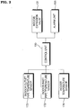
- FIG. 2 is a block diagram of the air conditioner in accordance with an embodiment of the present invention.
- the indoor outlet pipe temperature sensor 172 measures the temperature of the refrigerant discharged from the indoor heat exchanger 120.
- the indoor outlet pipe temperature sensor 172 is installed on the indoor outlet pipe 164.
- the indoor inlet pipe temperature sensor 173 measures the temperature of the refrigerant fed to the indoor heat exchanger 120.
- the indoor inlet pipe temperature sensor 173 is installed on the indoor inlet pipe 163 connecting the indoor heat exchanger 120 and the indoor expansion valve 131.
- the indoor temperature sensor 176 measures the temperature of indoor air.
- the indoor temperature sensor 176 is installed in the indoor unit IU.
- a control unit 190 detects whether or not the indoor expansion valve 131 is malfunctioning based on indoor unit pipe temperatures measured while opening and closing the indoor expansion valve 131.
- the indoor unit pipe temperature is a temperature measured by the indoor outlet pipe temperature sensor 172 or the indoor inlet pipe temperature sensor 173.
- the indoor unit pipe temperature may be the average value of the temperature measured by the indoor outlet pipe temperature sensor 172 and the temperature measured by the indoor inlet pipe temperature sensor 173.
- the control unit 190 detects abnormalities in the indoor unit pipe temperature when the indoor expansion valve 131 is opened and closed. The control unit 190 detects whether or not the indoor expansion valve 131 is malfunctioning by analyzing the variation in the indoor unit pipe temperature as the indoor expansion valve 131 is switched from the open state to the closed state. The control unit 190 then compares the measured variation of the indoor unit pipe temperature with the known variation of the indoor unit pipe temperature in a normal state. Further, the control unit 190 detects whether or not the indoor expansion valve 131 is malfunctioning by analyzing the variation in the indoor unit pipe temperature as the indoor expansion valve 131 is switched from the closed state to the open state. The control unit 190 then compares the measured variation of the indoor unit pipe temperature with the known variation of the indoor unit pipe temperature in the normal state.
- the control unit 190 may detect abnormalities in the difference between the indoor unit pipe temperature and an indoor air temperature when the indoor expansion valve 131 is opened and closed.
- the control unit 190 detects whether or not the indoor expansion pipe 131 is malfunctioning by analyzing the variation in the difference between the indoor unit pipe temperature and the indoor air temperature as the indoor expansion valve 131 is switched from the open state to the closed state.
- the control unit 190 then compares the measured variation of the difference between the indoor unit pipe temperature and the indoor air temperature with the known variation of the difference between the indoor unit pipe temperature and the indoor air temperature in a normal state.
- control unit 190 may initialize the indoor expansion valve 131 because the malfunction may be due to an incorrect determination of the initial open state of the indoor expansion valve 131. The control unit 190 may then again determine whether or not the indoor expansion valve 131 is malfunctioning. The initialization of the indoor expansion valve 131 is as described above.
- the current open state of the indoor expansion valve 131 may be lost by the control unit 190, such as when the power is turned off and then turned on. So while the control unit 90 indicates that the indoor expansion valve 131 is closed, the indoor expansion valve 131 may be substantially open. Thus, the control unit 190 detects that the indoor expansion valve 130 is malfunctioning. Therefore, the control unit 190 initializes the indoor expansion valve and then determines again whether or not the indoor expansion valve 131 is malfunctioning.
- control unit 190 may store an indication that the indoor expansion valve 131 is malfunctioning and/or provide a warning to the user by an alarm unit.
- the alarm unit 193 communicates the fact that the indoor expansion valve 131 is malfunctioning to a user either visually or through sound.
- the alarm unit 193 may inform other systems of the fact that the indoor expansion valve 131 is malfunctioning through a network.
- FIGs. 3(a) to 3(c) are graphs illustrating temperature variations when an indoor expansion valve switches between closed and open during the cooling operation of the air conditioner in accordance with an embodiment of the present invention.
- FIG. 3(a) illustrates the variation of the indoor unit pipe temperature when the indoor expansion valve 131 switches from closed to open during the cooling operation.
- the control unit 190 detects whether or not the indoor expansion valve 131 is operating normally by using a difference of the indoor unit pipe temperatures during a time period T1 and a time period T2.
- the control unit 190 opens the indoor expansion valve 131, a variation in the indoor unit pipe temperature is not greater than the variation during the normal operation of the indoor expansion valve 131. Further, if the indoor expansion valve 131 is initially closed but is not opened due to a malfunction and although the control unit 190 opens the indoor expansion valve 131, the indoor expansion valve 131 is not substantially opened and thus the low-temperature refrigerant does not flow. Therefore, the variation of the indoor unit pipe temperature is not greater than the variation during the normal operation of the indoor expansion valve 131. Therefore, if the difference of the indoor unit pipe temperatures between the time period T1 and the time period T2 is smaller than a predetermined reference value, the control unit 190 determines that the indoor expansion valve 131 is malfunctioning.
- FIG. 3(b) illustrates the variation of the indoor unit pipe temperature when the indoor expansion valve 131 switches from open to closed during the cooling operation.
- the control unit 190 detects whether or not the indoor expansion valve 131 is operating normally by using the difference of the indoor unit pipe temperatures during a time period T1 and a time period T2.
- the control unit 190 closes the indoor expansion valve 131, a variation in the indoor unit pipe temperature is not greater than the variation during the normal operation of the indoor expansion valve 131. Further, if the indoor expansion valve 131 is initially opened but is not closed or is partially closed due to a malfunction and although the control unit 190 closes the indoor expansion valve 131, the indoor expansion valve 131 is not substantially closed and thus the low-temperature refrigerant flows. Therefore, the variation of the indoor unit pipe temperature is not greater than the variation during the normal operation of the indoor expansion valve 131. Therefore, if the difference of the indoor unit pipe temperatures between the time period T1 and the time period T2 is smaller than a predetermining reference value, the control unit 190 determines that the indoor expansion valve 131 is malfunctioning.
- FIG. 3(c) illustrates the variation of the indoor unit pipe temperature when the indoor air temperature when the indoor expansion valve 131 switches from open to closed during the cooling operation.
- the control unit 190 detects whether or not the indoor expansion valve 131 is operating normally by using a difference between the indoor unit pipe temperatures and the indoor air temperature during the time period T1 and the time period T2.
- the indoor expansion valve 131 If the indoor expansion valve 131 is initially partially or completely closed due to a malfunction, the low-temperature refrigerant does not flow. Thus, a difference between the indoor unit pipe temperature and the indoor air temperature is smaller than that during normal operation of the indoor expansion valve 131. Further, if the indoor expansion valve 131 is initially opened but is not closed or is partially closed due to a malfunction and although the control unit 190 closes the indoor expansion valve 131, the indoor expansion valve 131 is not substantially closed and thus the low-temperature refrigerant flows. Thus, a difference between the indoor unit pipe temperature and the indoor air temperature is greater than that during the normal state of the indoor expansion valve 131. Therefore, if the difference of the indoor unit pipe temperature and the indoor air temperature during the time period T1 and the time period T2 is smaller or greater than a predetermined reference value, the control unit 190 determines that the indoor expansion valve 131 is malfunctioning.
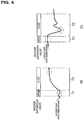
- FIGs. 4(a) and 4(b) are graphs illustrating temperature variations when the indoor expansion valve switches between closed and open during the heating operation of the air conditioner in accordance with an embodiment of the present invention.
- FIG. 4(a) illustrates the variation of the indoor unit pipe temperature when the indoor expansion valve 131 switches from closed to open during the heating operation.
- the control unit 190 detects whether or not the indoor expansion valve 131 is operating normally using a difference of the indoor unit pipe temperatures during a time period T1 and a time period T2.
- the control unit 190 opens the indoor expansion valve 131, a variation in the indoor unit pipe temperature is not greater than the variation during the normal operation of the indoor expansion valve 131. Further, if the indoor expansion valve 131 is initially closed but is not opened due to a malfunction and although the control unit 190 opens the indoor expansion valve 131, the indoor expansion valve 131 is not substantially opened and thus the high-temperature refrigerant does not flow. Therefore, the variation of the indoor unit pipe temperature is not greater than the variation during the normal operation of the indoor expansion valve 131. Therefore, if the difference of the indoor unit pipe temperatures between the time period T1 and the time period T2 is smaller than a predetermined reference value, the control unit 190 determines that the indoor expansion valve 131 is malfunctioning.
- FIG. 4(b) illustrates the variation of the indoor unit pipe temperature when the indoor expansion valve 131 switches from open to closed during the heating operation.
- the control unit 190 detects whether or not the indoor expansion valve 131 is operating normally by using the difference of the indoor unit pipe temperature during a time period T1 and the time period T2.
- the control unit 190 closes the indoor expansion valve 131, a variation in the indoor unit pipe temperature is not greater than the variation during the normal operation of the indoor expansion valve 131. Further, if the indoor expansion valve 131 is initially opened but is not closed or is partially closed due to a malfunction and although the control unit 190 closes the indoor expansion valve 131, the indoor expansion valve 131 is not substantially closed and thus the high-temperature refrigerant flows. Therefore, the variation of the indoor unit pipe temperature is not greater than the variation during the normal operation of the indoor expansion valve 131. Therefore, if the difference of the indoor unit pipe temperatures between the time period T1 and the time period T2 is smaller than a predetermined reference value, the control unit 190 determines that the indoor expansion valve 131 is malfunctioning.
- FIG. 5 is a flow chart illustrating a method for detecting a malfunction of an air conditioner in accordance with an embodiment of the present invention.
- the air conditioner is operated to detect whether or not the indoor expansion valve 131 is malfunctioning (S210).
- the control unit 190 performs a cooling operation or a heating operation and measures the indoor unit pipe temperature while opening and closing the indoor expansion valve 131. A detailed description of the above detection will be described later with reference to FIG. 6 .
- the control unit 190 detects whether or not a variation of the indoor unit pipe temperature is abnormal when the indoor expansion valve 131 is opened and closed. Further, the control unit 190 may detect whether or not a variation of a difference between the indoor unit pipe temperature and the indoor air temperature is abnormal when the indoor expansion valve 131 is opened and closed.
- the indoor expansion valve 131 may be initialized (S230). If the control unit 190 detects an indoor expansion valve 131 malfunction, it is preferable that the control unit 190 initialize the indoor expansion valve 131. Because the control unit 190 may detect that the indoor expansion valve 131 is malfunctioning due to an incorrect determination of the initial open state of the indoor expansion valve 131, the control unit 190 may initialize the indoor expansion valve 131 and then detect again whether or not the indoor expansion valve 131 is malfunctioning.
- the initialization of the indoor expansion valve 131 means initialization of the open state of the indoor expansion valve 131 by completely opening the indoor expansion valve 131 and then completely closing the indoor expansion valve 131. Other various methods of initializing the open state of the indoor expansion valve 131 may be used.
- the air conditioner is operated again to detect whether or not the indoor expansion valve 131 is malfunctioning (S240), and the control unit 190 performs the cooling operation or the heating operation of the air conditioner and measures the indoor unit pipe temperature while opening and closing the indoor expansion valve 131.
- any malfunction of the indoor expansion valve 131 is re-detected (S250), and the control unit 190 detects whether or not a variation of the indoor unit pipe temperature or a variation of a difference between the indoor unit pipe temperature and the indoor air temperature is abnormal when the indoor expansion valve 131 is opened and closed.
- control unit 190 If the control unit 190 detects an indoor expansion valve 131 malfunction, a warning indicating that the indoor expansion valve 131 is malfunctioning is given to the user (S260). If the control unit 190 detects an indoor expansion valve 131 malfunction even after the initialization of the indoor expansion valve 131, the control unit 190 may store an indication that the indoor expansion valve 131 is malfunctioning and/or provide a warning to the user by the alarm unit 193. The alarm unit 193 may display the fact that the indoor expansion valve 131 is malfunctioning to the user visually or through sound.
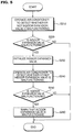
- FIG. 6 is a flow chart illustrating a method for detecting a malfunction of the indoor expansion valve of an air conditioner in accordance with an embodiment of the present invention.
- FIG. 6 illustrates in detail the operation of the air conditioner to detect whether or not the indoor expansion valve 131 is malfunctioning (S210, S240) and the detection whether or not the indoor expansion valve 131 is malfunctioning (S220, S250).
- the air conditioner is started (S310).
- the air conditioner may be in either cooling mode or a heating mode. Further, the air conditioner may be operated to detect whether or not the indoor expansion valve 131 is malfunctioning or may be operated normally to cool or heat an indoor space.
- an indoor unit pipe temperature and an indoor air temperature are measured (S320).
- the control unit 190 measures and tracks the indoor unit pipe temperature and the indoor air temperature.
- the indoor unit pipe temperature is a temperature measured by the indoor outlet pipe temperature sensor 172 or the indoor inlet pipe temperature sensor 173.
- the indoor unit pipe temperature may be the average value of the temperature measured by the indoor outlet pipe temperature sensor 172 and the temperature measured by the indoor inlet pipe temperature sensor 173.
- the indoor air temperature is a temperature of indoor air measured by the indoor temperature sensor 176.
- the indoor expansion valve 131 is opened to the set open state during the cooling operation, and is completely opened during the heating operation. Therefore, in order to detect whether or not the indoor expansion valve 131 is malfunctioning in the cooling operation, the indoor expansion valve 131 may be completely opened.
- the control unit 190 closes the opened indoor expansion valve 131 (S330).
- the indoor outlet pipe temperature sensor 172 or the indoor inlet pipe temperature sensor 173 continuously measures the indoor unit pipe temperature
- the indoor temperature sensor 176 continuously measures the indoor air temperature. Further, the control unit 190 continuously tracks the indoor unit pipe temperature and the indoor air temperature.
- the control unit 190 detects whether or not the indoor unit pipe temperature is abnormal (S340).
- the control unit 190 detects whether or not the indoor unit pipe temperature is abnormal by comparing a variation of the indoor unit pipe temperature during the open state of the indoor expansion valve 131 to the closed state of the indoor expansion valve 131 with that in the normal state.
- control unit 190 detects whether or not a variation of a difference between the indoor unit pipe temperature and the indoor air temperature is abnormal (S350).
- the control unit 190 detects whether or not the variation of the difference between the indoor unit pipe temperature and the indoor air temperature is abnormal by comparing the variation of the difference between the indoor unit pipe temperature and the indoor air temperature during the open state of the indoor expansion valve 131 to the closed state of the indoor expansion valve 131 with that during the normal state.
- the operation S350 may be performed if it is detected that the indoor unit pipe temperature is abnormal during the operation S340. In this case, precision in detecting whether or not the indoor expansion valve 131 is malfunctioning is increased.
- control unit 190 detects that the indoor expansion valve 131 is malfunctioning (S380).
- the control unit 190 opens the indoor expansion valve 131 (S360).
- the indoor outlet pipe temperature sensor 172 or the indoor inlet pipe temperature sensor 173 continuously measures the indoor unit pipe temperature
- the indoor temperature sensor 176 continuously measures the indoor air temperature. Further, the control unit 190 continuously tracks the indoor unit pipe temperature and the indoor air temperature.
- the operation S360 may be performed if the control unit detects that the variation of the difference between the indoor unit pipe temperature and the indoor air temperature is abnormal during operation S350. In this case, the precision in detecting whether or not the indoor expansion valve 131 is malfunctioning is increased.
- control unit 190 detects that the variation of the difference between the indoor unit pipe temperature and the indoor air temperature is abnormal, the control unit 190 detects that the indoor expansion valve 131 is malfunctioning (S380).
- the control unit 190 detects whether or not the indoor unit pipe temperature is abnormal (S370).
- the control unit 190 detects whether or not the indoor unit pipe temperature is abnormal by comparing a variation of the indoor unit pipe temperature during the closed state of the indoor expansion valve 131 to the open state of the indoor expansion valve 131 with that during the normal state.
- control unit 190 detects that the indoor unit pipe temperature is abnormal, the control unit 190 detects that the indoor expansion valve 131 is malfunctioning (S380).
Landscapes
- Engineering & Computer Science (AREA)
- Mechanical Engineering (AREA)
- General Engineering & Computer Science (AREA)
- Chemical & Material Sciences (AREA)
- Combustion & Propulsion (AREA)
- Human Computer Interaction (AREA)
- Health & Medical Sciences (AREA)
- Biomedical Technology (AREA)
- Physics & Mathematics (AREA)
- Thermal Sciences (AREA)
- Air Conditioning Control Device (AREA)
Claims (7)
- Procédé de détection d'un dysfonctionnement d'un climatiseur, comprenant :la mesure (S210) d'une température de tuyau d'unité intérieure autour d'un échangeur de chaleur intérieur (120) au cours d'un fonctionnement du climatiseur ;l'actionnement (S210) d'une vanne d'expansion intérieure (131) raccordée à l'échangeur de chaleur intérieur (120) dans un premier état ; etla détection (S220) si une variation de la température de tuyau d'unité intérieure est ou non anormale par la mesure de la température de tuyau d'unité intérieure après l'actionnement de la vanne d'expansion intérieure (131) dans le premier état ;l'initialisation (S230) de la vanne d'expansion intérieure, s'il est détecté que la variation de la température de tuyau d'unité intérieure est anormale ;la mesure de la température de tuyau d'unité intérieure lorsque le climatiseur fonctionne après l'initialisation de la vanne d'expansion intérieure (131) ;l'actionnement de la vanne d'expansion intérieure dans le premier état ; etla détection (S250) si une variation de la température de tuyau d'unité intérieure est ou non anormale par la mesure de la température de tuyau d'unité intérieure après l'actionnement de la vanne d'expansion intérieure (131) dans le premier état,dans lequel l'initialisation de la vanne d'expansion intérieure (131) comprend l'ouverture complète de la vanne d'expansion intérieure (131), puis la fermeture complète de la vanne d'expansion intérieure (131).
- Procédé selon la revendication 1, dans lequel la température de tuyau d'unité intérieure est une température d'un tuyau d'entrée intérieur (163) de l'échangeur de chaleur intérieur (120).
- Procédé selon la revendication 1, comprenant en outre :la mesure d'une température d'air intérieur ;le calcul d'une différence de température entre le tuyau d'unité intérieure (163) et l'air intérieur ; etla détection si une variation de la différence de température est ou non anormale par la mesure de la température de tuyau d'unité intérieure après l'actionnement de la vanne d'expansion intérieure (131) dans le premier état.
- Procédé selon la revendication 1, dans lequel la mesure de la température de tuyau d'unité intérieure inclut la mesure de la température d'un tuyau d'entrée intérieur (163) et d'un tuyau de sortie intérieur (169) de l'échangeur de chaleur (120).
- Procédé selon la revendication 1, comprenant en outre :l'actionnement de la vanne d'expansion intérieure (131) dans un deuxième état ; etla détection si une variation de la température de tuyau d'unité intérieure est ou non anormale par la mesure de la température de tuyau d'unité intérieure après l'ouverture de la vanne d'expansion intérieure (131) .
- Procédé selon la revendication 1, comprenant en outre l'avertissement (S260) que la vanne d'expansion intérieure (131) présente un dysfonctionnement, s'il est détecté que la variation de la température de tuyau d'unité intérieure est anormale.
- Climatiseur comprenant :un échangeur de chaleur intérieur (120) incluant un frigorigène qui échange une chaleur avec un air intérieur ;une vanne d'expansion intérieure (131) raccordée à l'échangeur de chaleur intérieur (120) pour réguler un flux de frigorigène ;un capteur de température de tuyau d'entrée intérieur (173) installé entre l'échangeur de chaleur intérieur (120) et la vanne d'expansion intérieure (131) ;un capteur de température de tuyau de sortie intérieur (172) installé sur un tuyau de sortie intérieur (164) de l'échangeur de chaleur intérieur (120) ; etune unité de commande (190) apte à exécuter le procédé selon l'une quelconque des revendications précédentes.
Applications Claiming Priority (2)
| Application Number | Priority Date | Filing Date | Title |
|---|---|---|---|
| KR1020090000924A KR20100081620A (ko) | 2009-01-06 | 2009-01-06 | 공기조화기 및 공기조화기의 고장 판단 방법 |
| KR1020090062721A KR101590367B1 (ko) | 2009-07-09 | 2009-07-09 | 공기조화기 및 공기조화기의 고장 판단 방법 |
Publications (3)
| Publication Number | Publication Date |
|---|---|
| EP2204621A2 EP2204621A2 (fr) | 2010-07-07 |
| EP2204621A3 EP2204621A3 (fr) | 2012-07-04 |
| EP2204621B1 true EP2204621B1 (fr) | 2019-03-06 |
Family
ID=42103380
Family Applications (1)
| Application Number | Title | Priority Date | Filing Date |
|---|---|---|---|
| EP10000069.4A Active EP2204621B1 (fr) | 2009-01-06 | 2010-01-07 | Climatiseur et procédé de détection de dysfonctionnements correspondant |
Country Status (2)
| Country | Link |
|---|---|
| US (1) | US20100174412A1 (fr) |
| EP (1) | EP2204621B1 (fr) |
Families Citing this family (25)
| Publication number | Priority date | Publication date | Assignee | Title |
|---|---|---|---|---|
| JP5404487B2 (ja) * | 2010-03-23 | 2014-01-29 | 三菱電機株式会社 | 多室形空気調和機 |
| JP5640710B2 (ja) * | 2010-12-09 | 2014-12-17 | パナソニック株式会社 | 空気調和機 |
| KR20120129111A (ko) * | 2011-05-19 | 2012-11-28 | 엘지전자 주식회사 | 공기조화기 |
| KR101324935B1 (ko) * | 2011-10-11 | 2013-11-01 | 엘지전자 주식회사 | 공기조화기 |
| JP5858824B2 (ja) * | 2012-03-01 | 2016-02-10 | 三菱電機株式会社 | マルチ形空気調和機 |
| IN2014DN06976A (fr) * | 2012-04-17 | 2015-04-10 | Danfoss As | |
| US9459033B2 (en) * | 2012-08-02 | 2016-10-04 | Mitsubishi Electric Corporation | Multi air-conditioning apparatus |
| US9829230B2 (en) * | 2013-02-28 | 2017-11-28 | Mitsubishi Electric Corporation | Air conditioning apparatus |
| CN104566762B (zh) * | 2013-10-12 | 2018-03-20 | 珠海格力电器股份有限公司 | 除湿机的出风口异常监控方法及系统 |
| CN103807980B (zh) * | 2014-03-04 | 2016-03-30 | 施晓亚 | 一种预测中央空调异常的方法 |
| CN105320100A (zh) * | 2014-07-31 | 2016-02-10 | 中兴通讯股份有限公司 | 家居设备控制方法及装置 |
| US10161661B2 (en) * | 2014-11-04 | 2018-12-25 | Mitsubishi Electric Corporation | Refrigeration cycle apparatus, and abnormality detection system for refrigeration cycle apparatus |
| JP6007965B2 (ja) * | 2014-12-15 | 2016-10-19 | ダイキン工業株式会社 | 空気調和装置 |
| WO2017212631A1 (fr) * | 2016-06-10 | 2017-12-14 | 三菱電機株式会社 | Dispositif de climatisation de véhicule et système de détection d'anomalie pour dispositif de climatisation de véhicule |
| CN106352473B (zh) * | 2016-08-19 | 2019-08-30 | 广东美的暖通设备有限公司 | 多联机系统及其过冷支路阀体组件的故障检测方法 |
| CN107702270A (zh) * | 2017-10-11 | 2018-02-16 | 珠海格力电器股份有限公司 | 电子膨胀阀控制方法和装置、空调 |
| CN109114765B (zh) * | 2018-10-26 | 2021-05-28 | 广东美的制冷设备有限公司 | 空调器的出风控制方法、控制装置、空调器及存储介质 |
| CN109708269B (zh) * | 2019-02-25 | 2023-11-24 | 珠海格力电器股份有限公司 | 空调及其电加热器控制方法、装置和设备 |
| CN112178976A (zh) * | 2019-07-03 | 2021-01-05 | 开利公司 | 热交换单元,热交换系统及其中确定控制阀故障的方法 |
| GB2604464B (en) * | 2019-12-04 | 2023-09-20 | Mitsubishi Electric Corp | Controller for refrigeration cycle apparatus and refrigeration cycle |
| JP6793862B1 (ja) * | 2020-01-14 | 2020-12-02 | 三菱電機株式会社 | 冷凍サイクル装置 |
| CN111397084A (zh) * | 2020-03-31 | 2020-07-10 | 三一海洋重工有限公司 | 空调状态监控装置、方法及系统 |
| CN112880127B (zh) * | 2021-01-28 | 2022-06-21 | 广东美的制冷设备有限公司 | 一种故障检测方法、装置、设备及存储介质 |
| CN112984662B (zh) * | 2021-03-31 | 2023-04-07 | 广东积微科技有限公司 | 一种热回收空调热水系统及其制冷剂流量控制方法 |
| CN114754413B (zh) * | 2022-04-11 | 2023-10-27 | 青岛海信日立空调系统有限公司 | 一种多联机空调系统及故障定位方法 |
Family Cites Families (18)
| Publication number | Priority date | Publication date | Assignee | Title |
|---|---|---|---|---|
| US5623834A (en) * | 1995-05-03 | 1997-04-29 | Copeland Corporation | Diagnostics for a heating and cooling system |
| US5970726A (en) * | 1997-04-08 | 1999-10-26 | Heatcraft Inc. | Defrost control for space cooling system |
| US5791155A (en) * | 1997-06-06 | 1998-08-11 | Carrier Corporation | System for monitoring expansion valve |
| JPH11325662A (ja) * | 1998-05-15 | 1999-11-26 | Mitsubishi Electric Corp | 電子式膨張弁の動作不良調整装置 |
| US6209338B1 (en) * | 1998-07-15 | 2001-04-03 | William Bradford Thatcher, Jr. | Systems and methods for controlling refrigerant charge |
| US6233952B1 (en) * | 1999-01-19 | 2001-05-22 | Carrier Corporation | Pretrip routine comprising of individual refrigeration system components |
| JP2000274896A (ja) * | 1999-03-24 | 2000-10-06 | Tokyo Gas Co Ltd | 膨張弁の異常検知方法及び空調装置 |
| JP2001027455A (ja) * | 1999-05-13 | 2001-01-30 | Denso Corp | ヒートポンプ式空調装置 |
| KR100432224B1 (ko) * | 2002-05-01 | 2004-05-20 | 삼성전자주식회사 | 공기 조화기의 냉매 누설 검출 방법 |
| JP4032993B2 (ja) * | 2003-02-21 | 2008-01-16 | 松下電器産業株式会社 | 空気調和機 |
| US20050126190A1 (en) * | 2003-12-10 | 2005-06-16 | Alexander Lifson | Loss of refrigerant charge and expansion valve malfunction detection |
| US7159408B2 (en) * | 2004-07-28 | 2007-01-09 | Carrier Corporation | Charge loss detection and prognostics for multi-modular split systems |
| KR100631540B1 (ko) * | 2004-10-26 | 2006-10-09 | 엘지전자 주식회사 | 히트 펌프식 멀티형 공기조화기의 가스관 막힘 검출시스템및 방법 |
| KR100631539B1 (ko) * | 2004-10-26 | 2006-10-09 | 엘지전자 주식회사 | 멀티형 공기조화기의 통신선 오결선 검출시스템 및 방법 |
| KR100640851B1 (ko) * | 2004-12-09 | 2006-11-02 | 엘지전자 주식회사 | 멀티 에어컨 시스템의 상태 모니터링 장치 및 그 방법 |
| KR20070017269A (ko) * | 2005-08-06 | 2007-02-09 | 삼성전자주식회사 | 멀티 에어컨시스템의 배관점검운전방법 및 배관점검방법 |
| JP4762797B2 (ja) * | 2006-06-12 | 2011-08-31 | 三菱電機ビルテクノサービス株式会社 | マルチ式空気調和システム |
| US20080134699A1 (en) * | 2006-11-08 | 2008-06-12 | Imi Cornelius Inc. | Refrigeration systems having prescriptive refrigerant flow control |
-
2010
- 2010-01-05 US US12/652,348 patent/US20100174412A1/en not_active Abandoned
- 2010-01-07 EP EP10000069.4A patent/EP2204621B1/fr active Active
Non-Patent Citations (1)
| Title |
|---|
| None * |
Also Published As
| Publication number | Publication date |
|---|---|
| EP2204621A3 (fr) | 2012-07-04 |
| EP2204621A2 (fr) | 2010-07-07 |
| US20100174412A1 (en) | 2010-07-08 |
Similar Documents
| Publication | Publication Date | Title |
|---|---|---|
| EP2204621B1 (fr) | Climatiseur et procédé de détection de dysfonctionnements correspondant | |
| EP2728280B1 (fr) | Climatiseur et son procédé de fonctionnement | |
| EP2354724B1 (fr) | Climatiseur d'air et son procédé de commande | |
| KR101270540B1 (ko) | 멀티형 공기조화기의 배관연결 점검장치 및 그 방법 | |
| US7765812B2 (en) | System for detecting mis-connected state between communication lines for multi-type air conditioner and method thereof | |
| EP1706684A2 (fr) | Procede pour diagnostiquer une perte de charge refrigerante dans un systeme refrigerant | |
| US11874039B2 (en) | Refrigeration cycle apparatus | |
| KR20070017269A (ko) | 멀티 에어컨시스템의 배관점검운전방법 및 배관점검방법 | |
| CN111486612A (zh) | 多联机系统及其制热阀泄漏检测方法、装置和存储介质 | |
| KR100667277B1 (ko) | 다배관 멀티형 공기조화기의 배관연결 점검방법 | |
| KR20110105230A (ko) | 공기조화기 및 그 운전방법 | |
| JP7142789B2 (ja) | 空気調和機 | |
| KR101598787B1 (ko) | 공기조화기 및 그 운전 방법 | |
| KR102498549B1 (ko) | 공기조화기의 제어 방법 | |
| KR20070077639A (ko) | 멀티 공기조화기 및 그 제어방법 | |
| JP5199713B2 (ja) | マルチ型空気調和機、室内ユニットの室内側電子膨張弁の動作確認方法、コンピュータプログラムおよび故障診断装置 | |
| JPH076661B2 (ja) | 空気調和装置の遠隔制御装置 | |
| JP3123873B2 (ja) | 空気調和装置 | |
| KR101584530B1 (ko) | 공기조화기 및 공기조화기 시운전 방법 | |
| KR102521852B1 (ko) | 공기조화기 | |
| CN111503813B (zh) | 多联机系统及其控制方法和装置 | |
| KR101000050B1 (ko) | 멀티 공기조화기의 냉매량 부족방지제어방법 | |
| KR102470528B1 (ko) | 공기조화 시스템 및 공기조화 시스템의 배관 탐색 방법 | |
| KR101590367B1 (ko) | 공기조화기 및 공기조화기의 고장 판단 방법 | |
| KR101294738B1 (ko) | 공기조화기 및 그 운전 방법 |
Legal Events
| Date | Code | Title | Description |
|---|---|---|---|
| PUAI | Public reference made under article 153(3) epc to a published international application that has entered the european phase |
Free format text: ORIGINAL CODE: 0009012 |
|
| AK | Designated contracting states |
Kind code of ref document: A2 Designated state(s): AT BE BG CH CY CZ DE DK EE ES FI FR GB GR HR HU IE IS IT LI LT LU LV MC MK MT NL NO PL PT RO SE SI SK SM TR |
|
| AX | Request for extension of the european patent |
Extension state: AL BA RS |
|
| PUAL | Search report despatched |
Free format text: ORIGINAL CODE: 0009013 |
|
| AK | Designated contracting states |
Kind code of ref document: A3 Designated state(s): AT BE BG CH CY CZ DE DK EE ES FI FR GB GR HR HU IE IS IT LI LT LU LV MC MK MT NL NO PL PT RO SE SI SK SM TR |
|
| AX | Request for extension of the european patent |
Extension state: AL BA RS |
|
| RIC1 | Information provided on ipc code assigned before grant |
Ipc: F25B 49/00 20060101ALI20120530BHEP Ipc: F24F 11/00 20060101AFI20120530BHEP |
|
| 17P | Request for examination filed |
Effective date: 20121221 |
|
| 17Q | First examination report despatched |
Effective date: 20151223 |
|
| REG | Reference to a national code |
Ref country code: DE Ref legal event code: R079 Ref document number: 602010057341 Country of ref document: DE Free format text: PREVIOUS MAIN CLASS: F24F0011000000 Ipc: F24F0011300000 |
|
| RIC1 | Information provided on ipc code assigned before grant |
Ipc: F25B 49/00 20060101ALI20180622BHEP Ipc: F24F 140/20 20180101ALI20180622BHEP Ipc: F24F 11/30 20180101AFI20180622BHEP |
|
| GRAP | Despatch of communication of intention to grant a patent |
Free format text: ORIGINAL CODE: EPIDOSNIGR1 |
|
| STAA | Information on the status of an ep patent application or granted ep patent |
Free format text: STATUS: GRANT OF PATENT IS INTENDED |
|
| INTG | Intention to grant announced |
Effective date: 20180810 |
|
| RIN1 | Information on inventor provided before grant (corrected) |
Inventor name: OH, SAI KEE Inventor name: KWON, KI BAIK Inventor name: KIM, SUNG HWAN |
|
| RAP1 | Party data changed (applicant data changed or rights of an application transferred) |
Owner name: LG ELECTRONICS INC. |
|
| GRAS | Grant fee paid |
Free format text: ORIGINAL CODE: EPIDOSNIGR3 |
|
| GRAA | (expected) grant |
Free format text: ORIGINAL CODE: 0009210 |
|
| STAA | Information on the status of an ep patent application or granted ep patent |
Free format text: STATUS: THE PATENT HAS BEEN GRANTED |
|
| AK | Designated contracting states |
Kind code of ref document: B1 Designated state(s): AT BE BG CH CY CZ DE DK EE ES FI FR GB GR HR HU IE IS IT LI LT LU LV MC MK MT NL NO PL PT RO SE SI SK SM TR |
|
| REG | Reference to a national code |
Ref country code: GB Ref legal event code: FG4D |
|
| REG | Reference to a national code |
Ref country code: AT Ref legal event code: REF Ref document number: 1105074 Country of ref document: AT Kind code of ref document: T Effective date: 20190315 Ref country code: CH Ref legal event code: EP |
|
| REG | Reference to a national code |
Ref country code: DE Ref legal event code: R096 Ref document number: 602010057341 Country of ref document: DE |
|
| REG | Reference to a national code |
Ref country code: IE Ref legal event code: FG4D |
|
| REG | Reference to a national code |
Ref country code: NL Ref legal event code: MP Effective date: 20190306 |
|
| REG | Reference to a national code |
Ref country code: LT Ref legal event code: MG4D |
|
| PG25 | Lapsed in a contracting state [announced via postgrant information from national office to epo] |
Ref country code: FI Free format text: LAPSE BECAUSE OF FAILURE TO SUBMIT A TRANSLATION OF THE DESCRIPTION OR TO PAY THE FEE WITHIN THE PRESCRIBED TIME-LIMIT Effective date: 20190306 Ref country code: SE Free format text: LAPSE BECAUSE OF FAILURE TO SUBMIT A TRANSLATION OF THE DESCRIPTION OR TO PAY THE FEE WITHIN THE PRESCRIBED TIME-LIMIT Effective date: 20190306 Ref country code: LT Free format text: LAPSE BECAUSE OF FAILURE TO SUBMIT A TRANSLATION OF THE DESCRIPTION OR TO PAY THE FEE WITHIN THE PRESCRIBED TIME-LIMIT Effective date: 20190306 Ref country code: NO Free format text: LAPSE BECAUSE OF FAILURE TO SUBMIT A TRANSLATION OF THE DESCRIPTION OR TO PAY THE FEE WITHIN THE PRESCRIBED TIME-LIMIT Effective date: 20190606 |
|
| PG25 | Lapsed in a contracting state [announced via postgrant information from national office to epo] |
Ref country code: BG Free format text: LAPSE BECAUSE OF FAILURE TO SUBMIT A TRANSLATION OF THE DESCRIPTION OR TO PAY THE FEE WITHIN THE PRESCRIBED TIME-LIMIT Effective date: 20190606 Ref country code: LV Free format text: LAPSE BECAUSE OF FAILURE TO SUBMIT A TRANSLATION OF THE DESCRIPTION OR TO PAY THE FEE WITHIN THE PRESCRIBED TIME-LIMIT Effective date: 20190306 Ref country code: HR Free format text: LAPSE BECAUSE OF FAILURE TO SUBMIT A TRANSLATION OF THE DESCRIPTION OR TO PAY THE FEE WITHIN THE PRESCRIBED TIME-LIMIT Effective date: 20190306 Ref country code: NL Free format text: LAPSE BECAUSE OF FAILURE TO SUBMIT A TRANSLATION OF THE DESCRIPTION OR TO PAY THE FEE WITHIN THE PRESCRIBED TIME-LIMIT Effective date: 20190306 |
|
| REG | Reference to a national code |
Ref country code: AT Ref legal event code: MK05 Ref document number: 1105074 Country of ref document: AT Kind code of ref document: T Effective date: 20190306 |
|
| PG25 | Lapsed in a contracting state [announced via postgrant information from national office to epo] |
Ref country code: RO Free format text: LAPSE BECAUSE OF FAILURE TO SUBMIT A TRANSLATION OF THE DESCRIPTION OR TO PAY THE FEE WITHIN THE PRESCRIBED TIME-LIMIT Effective date: 20190306 Ref country code: ES Free format text: LAPSE BECAUSE OF FAILURE TO SUBMIT A TRANSLATION OF THE DESCRIPTION OR TO PAY THE FEE WITHIN THE PRESCRIBED TIME-LIMIT Effective date: 20190306 Ref country code: IT Free format text: LAPSE BECAUSE OF FAILURE TO SUBMIT A TRANSLATION OF THE DESCRIPTION OR TO PAY THE FEE WITHIN THE PRESCRIBED TIME-LIMIT Effective date: 20190306 Ref country code: CZ Free format text: LAPSE BECAUSE OF FAILURE TO SUBMIT A TRANSLATION OF THE DESCRIPTION OR TO PAY THE FEE WITHIN THE PRESCRIBED TIME-LIMIT Effective date: 20190306 Ref country code: SK Free format text: LAPSE BECAUSE OF FAILURE TO SUBMIT A TRANSLATION OF THE DESCRIPTION OR TO PAY THE FEE WITHIN THE PRESCRIBED TIME-LIMIT Effective date: 20190306 Ref country code: PT Free format text: LAPSE BECAUSE OF FAILURE TO SUBMIT A TRANSLATION OF THE DESCRIPTION OR TO PAY THE FEE WITHIN THE PRESCRIBED TIME-LIMIT Effective date: 20190706 Ref country code: EE Free format text: LAPSE BECAUSE OF FAILURE TO SUBMIT A TRANSLATION OF THE DESCRIPTION OR TO PAY THE FEE WITHIN THE PRESCRIBED TIME-LIMIT Effective date: 20190306 |
|
| PG25 | Lapsed in a contracting state [announced via postgrant information from national office to epo] |
Ref country code: PL Free format text: LAPSE BECAUSE OF FAILURE TO SUBMIT A TRANSLATION OF THE DESCRIPTION OR TO PAY THE FEE WITHIN THE PRESCRIBED TIME-LIMIT Effective date: 20190306 Ref country code: SM Free format text: LAPSE BECAUSE OF FAILURE TO SUBMIT A TRANSLATION OF THE DESCRIPTION OR TO PAY THE FEE WITHIN THE PRESCRIBED TIME-LIMIT Effective date: 20190306 |
|
| REG | Reference to a national code |
Ref country code: DE Ref legal event code: R097 Ref document number: 602010057341 Country of ref document: DE |
|
| PG25 | Lapsed in a contracting state [announced via postgrant information from national office to epo] |
Ref country code: IS Free format text: LAPSE BECAUSE OF FAILURE TO SUBMIT A TRANSLATION OF THE DESCRIPTION OR TO PAY THE FEE WITHIN THE PRESCRIBED TIME-LIMIT Effective date: 20190706 Ref country code: AT Free format text: LAPSE BECAUSE OF FAILURE TO SUBMIT A TRANSLATION OF THE DESCRIPTION OR TO PAY THE FEE WITHIN THE PRESCRIBED TIME-LIMIT Effective date: 20190306 |
|
| PLBE | No opposition filed within time limit |
Free format text: ORIGINAL CODE: 0009261 |
|
| STAA | Information on the status of an ep patent application or granted ep patent |
Free format text: STATUS: NO OPPOSITION FILED WITHIN TIME LIMIT |
|
| PG25 | Lapsed in a contracting state [announced via postgrant information from national office to epo] |
Ref country code: DK Free format text: LAPSE BECAUSE OF FAILURE TO SUBMIT A TRANSLATION OF THE DESCRIPTION OR TO PAY THE FEE WITHIN THE PRESCRIBED TIME-LIMIT Effective date: 20190306 |
|
| 26N | No opposition filed |
Effective date: 20191209 |
|
| PG25 | Lapsed in a contracting state [announced via postgrant information from national office to epo] |
Ref country code: SI Free format text: LAPSE BECAUSE OF FAILURE TO SUBMIT A TRANSLATION OF THE DESCRIPTION OR TO PAY THE FEE WITHIN THE PRESCRIBED TIME-LIMIT Effective date: 20190306 |
|
| PG25 | Lapsed in a contracting state [announced via postgrant information from national office to epo] |
Ref country code: TR Free format text: LAPSE BECAUSE OF FAILURE TO SUBMIT A TRANSLATION OF THE DESCRIPTION OR TO PAY THE FEE WITHIN THE PRESCRIBED TIME-LIMIT Effective date: 20190306 |
|
| PGFP | Annual fee paid to national office [announced via postgrant information from national office to epo] |
Ref country code: DE Payment date: 20191205 Year of fee payment: 11 |
|
| PG25 | Lapsed in a contracting state [announced via postgrant information from national office to epo] |
Ref country code: MC Free format text: LAPSE BECAUSE OF FAILURE TO SUBMIT A TRANSLATION OF THE DESCRIPTION OR TO PAY THE FEE WITHIN THE PRESCRIBED TIME-LIMIT Effective date: 20190306 |
|
| REG | Reference to a national code |
Ref country code: CH Ref legal event code: PL |
|
| GBPC | Gb: european patent ceased through non-payment of renewal fee |
Effective date: 20200107 |
|
| REG | Reference to a national code |
Ref country code: BE Ref legal event code: MM Effective date: 20200131 |
|
| PG25 | Lapsed in a contracting state [announced via postgrant information from national office to epo] |
Ref country code: FR Free format text: LAPSE BECAUSE OF NON-PAYMENT OF DUE FEES Effective date: 20200131 Ref country code: GB Free format text: LAPSE BECAUSE OF NON-PAYMENT OF DUE FEES Effective date: 20200107 Ref country code: LU Free format text: LAPSE BECAUSE OF NON-PAYMENT OF DUE FEES Effective date: 20200107 |
|
| PG25 | Lapsed in a contracting state [announced via postgrant information from national office to epo] |
Ref country code: BE Free format text: LAPSE BECAUSE OF NON-PAYMENT OF DUE FEES Effective date: 20200131 Ref country code: CH Free format text: LAPSE BECAUSE OF NON-PAYMENT OF DUE FEES Effective date: 20200131 Ref country code: LI Free format text: LAPSE BECAUSE OF NON-PAYMENT OF DUE FEES Effective date: 20200131 |
|
| PG25 | Lapsed in a contracting state [announced via postgrant information from national office to epo] |
Ref country code: IE Free format text: LAPSE BECAUSE OF NON-PAYMENT OF DUE FEES Effective date: 20200107 |
|
| REG | Reference to a national code |
Ref country code: DE Ref legal event code: R119 Ref document number: 602010057341 Country of ref document: DE |
|
| PG25 | Lapsed in a contracting state [announced via postgrant information from national office to epo] |
Ref country code: DE Free format text: LAPSE BECAUSE OF NON-PAYMENT OF DUE FEES Effective date: 20210803 |
|
| PG25 | Lapsed in a contracting state [announced via postgrant information from national office to epo] |
Ref country code: MT Free format text: LAPSE BECAUSE OF FAILURE TO SUBMIT A TRANSLATION OF THE DESCRIPTION OR TO PAY THE FEE WITHIN THE PRESCRIBED TIME-LIMIT Effective date: 20190306 Ref country code: CY Free format text: LAPSE BECAUSE OF FAILURE TO SUBMIT A TRANSLATION OF THE DESCRIPTION OR TO PAY THE FEE WITHIN THE PRESCRIBED TIME-LIMIT Effective date: 20190306 |
|
| PG25 | Lapsed in a contracting state [announced via postgrant information from national office to epo] |
Ref country code: MK Free format text: LAPSE BECAUSE OF FAILURE TO SUBMIT A TRANSLATION OF THE DESCRIPTION OR TO PAY THE FEE WITHIN THE PRESCRIBED TIME-LIMIT Effective date: 20190306 |
|
| PG25 | Lapsed in a contracting state [announced via postgrant information from national office to epo] |
Ref country code: GR Free format text: LAPSE BECAUSE OF FAILURE TO SUBMIT A TRANSLATION OF THE DESCRIPTION OR TO PAY THE FEE WITHIN THE PRESCRIBED TIME-LIMIT Effective date: 20190306 |