EP2204621B1 - Air conditioner and method for detecting malfunction thereof - Google Patents
Air conditioner and method for detecting malfunction thereof Download PDFInfo
- Publication number
- EP2204621B1 EP2204621B1 EP10000069.4A EP10000069A EP2204621B1 EP 2204621 B1 EP2204621 B1 EP 2204621B1 EP 10000069 A EP10000069 A EP 10000069A EP 2204621 B1 EP2204621 B1 EP 2204621B1
- Authority
- EP
- European Patent Office
- Prior art keywords
- indoor
- expansion valve
- temperature
- indoor expansion
- pipe temperature
- Prior art date
- Legal status (The legal status is an assumption and is not a legal conclusion. Google has not performed a legal analysis and makes no representation as to the accuracy of the status listed.)
- Active
Links
Images


Classifications
-
- F—MECHANICAL ENGINEERING; LIGHTING; HEATING; WEAPONS; BLASTING
- F24—HEATING; RANGES; VENTILATING
- F24F—AIR-CONDITIONING; AIR-HUMIDIFICATION; VENTILATION; USE OF AIR CURRENTS FOR SCREENING
- F24F11/00—Control or safety arrangements
- F24F11/30—Control or safety arrangements for purposes related to the operation of the system, e.g. for safety or monitoring
- F24F11/32—Responding to malfunctions or emergencies
- F24F11/38—Failure diagnosis
-
- F—MECHANICAL ENGINEERING; LIGHTING; HEATING; WEAPONS; BLASTING
- F24—HEATING; RANGES; VENTILATING
- F24F—AIR-CONDITIONING; AIR-HUMIDIFICATION; VENTILATION; USE OF AIR CURRENTS FOR SCREENING
- F24F11/00—Control or safety arrangements
- F24F11/50—Control or safety arrangements characterised by user interfaces or communication
- F24F11/52—Indication arrangements, e.g. displays
- F24F11/526—Indication arrangements, e.g. displays giving audible indications
-
- F—MECHANICAL ENGINEERING; LIGHTING; HEATING; WEAPONS; BLASTING
- F24—HEATING; RANGES; VENTILATING
- F24F—AIR-CONDITIONING; AIR-HUMIDIFICATION; VENTILATION; USE OF AIR CURRENTS FOR SCREENING
- F24F11/00—Control or safety arrangements
- F24F11/70—Control systems characterised by their outputs; Constructional details thereof
- F24F11/80—Control systems characterised by their outputs; Constructional details thereof for controlling the temperature of the supplied air
- F24F11/83—Control systems characterised by their outputs; Constructional details thereof for controlling the temperature of the supplied air by controlling the supply of heat-exchange fluids to heat-exchangers
- F24F11/84—Control systems characterised by their outputs; Constructional details thereof for controlling the temperature of the supplied air by controlling the supply of heat-exchange fluids to heat-exchangers using valves
-
- F—MECHANICAL ENGINEERING; LIGHTING; HEATING; WEAPONS; BLASTING
- F25—REFRIGERATION OR COOLING; COMBINED HEATING AND REFRIGERATION SYSTEMS; HEAT PUMP SYSTEMS; MANUFACTURE OR STORAGE OF ICE; LIQUEFACTION SOLIDIFICATION OF GASES
- F25B—REFRIGERATION MACHINES, PLANTS OR SYSTEMS; COMBINED HEATING AND REFRIGERATION SYSTEMS; HEAT PUMP SYSTEMS
- F25B49/00—Arrangement or mounting of control or safety devices
- F25B49/005—Arrangement or mounting of control or safety devices of safety devices
-
- F—MECHANICAL ENGINEERING; LIGHTING; HEATING; WEAPONS; BLASTING
- F24—HEATING; RANGES; VENTILATING
- F24F—AIR-CONDITIONING; AIR-HUMIDIFICATION; VENTILATION; USE OF AIR CURRENTS FOR SCREENING
- F24F11/00—Control or safety arrangements
- F24F11/30—Control or safety arrangements for purposes related to the operation of the system, e.g. for safety or monitoring
- F24F11/32—Responding to malfunctions or emergencies
-
- F—MECHANICAL ENGINEERING; LIGHTING; HEATING; WEAPONS; BLASTING
- F24—HEATING; RANGES; VENTILATING
- F24F—AIR-CONDITIONING; AIR-HUMIDIFICATION; VENTILATION; USE OF AIR CURRENTS FOR SCREENING
- F24F2140/00—Control inputs relating to system states
-
- F—MECHANICAL ENGINEERING; LIGHTING; HEATING; WEAPONS; BLASTING
- F24—HEATING; RANGES; VENTILATING
- F24F—AIR-CONDITIONING; AIR-HUMIDIFICATION; VENTILATION; USE OF AIR CURRENTS FOR SCREENING
- F24F2140/00—Control inputs relating to system states
- F24F2140/20—Heat-exchange fluid temperature
-
- F—MECHANICAL ENGINEERING; LIGHTING; HEATING; WEAPONS; BLASTING
- F25—REFRIGERATION OR COOLING; COMBINED HEATING AND REFRIGERATION SYSTEMS; HEAT PUMP SYSTEMS; MANUFACTURE OR STORAGE OF ICE; LIQUEFACTION SOLIDIFICATION OF GASES
- F25B—REFRIGERATION MACHINES, PLANTS OR SYSTEMS; COMBINED HEATING AND REFRIGERATION SYSTEMS; HEAT PUMP SYSTEMS
- F25B2313/00—Compression machines, plants or systems with reversible cycle not otherwise provided for
- F25B2313/031—Sensor arrangements
- F25B2313/0314—Temperature sensors near the indoor heat exchanger
-
- F—MECHANICAL ENGINEERING; LIGHTING; HEATING; WEAPONS; BLASTING
- F25—REFRIGERATION OR COOLING; COMBINED HEATING AND REFRIGERATION SYSTEMS; HEAT PUMP SYSTEMS; MANUFACTURE OR STORAGE OF ICE; LIQUEFACTION SOLIDIFICATION OF GASES
- F25B—REFRIGERATION MACHINES, PLANTS OR SYSTEMS; COMBINED HEATING AND REFRIGERATION SYSTEMS; HEAT PUMP SYSTEMS
- F25B2700/00—Sensing or detecting of parameters; Sensors therefor
- F25B2700/19—Pressures
- F25B2700/193—Pressures of the compressor
- F25B2700/1931—Discharge pressures
-
- F—MECHANICAL ENGINEERING; LIGHTING; HEATING; WEAPONS; BLASTING
- F25—REFRIGERATION OR COOLING; COMBINED HEATING AND REFRIGERATION SYSTEMS; HEAT PUMP SYSTEMS; MANUFACTURE OR STORAGE OF ICE; LIQUEFACTION SOLIDIFICATION OF GASES
- F25B—REFRIGERATION MACHINES, PLANTS OR SYSTEMS; COMBINED HEATING AND REFRIGERATION SYSTEMS; HEAT PUMP SYSTEMS
- F25B2700/00—Sensing or detecting of parameters; Sensors therefor
- F25B2700/21—Temperatures
- F25B2700/2115—Temperatures of a compressor or the drive means therefor
- F25B2700/21152—Temperatures of a compressor or the drive means therefor at the discharge side of the compressor
Definitions
- the present invention relates to an air conditioner and a method for detecting a malfunction thereof, and more particularly to an air conditioner, which automatically detects a malfunction, and a method for automatically detecting a malfunction of the air conditioner.
- air conditioners are apparatuses that maintain air in a designated space at a temperature and humidity level that is comfortable to humans. These air conditioners absorb heat in a designated space, or emit heat into the space, and thus maintain temperature and humidity of the space at suitable levels. Each air conditioner has an indoor unit, which absorbs heat in a designated space or emits heat into the space.
- an indoor expansion valve to control refrigerant flow may be included in the indoor unit.
- a technician monitors the operating state of the indoor unit.
- EP 1 750 073 A2 describes a pipe inspection method and a pipe-inspection operation method of a multi-air conditioner.
- indoor heat exchangers are adapted to serve as condensers and outdoor heat exchanger is adapted to serve as an evaporator.
- expansion valves are fully open to set a reference point for valve opening control. That is, the valve opening degree of an expansion valve is controlled in 500 steps from a fully open position of the expansion valve to a fully closed position thereof, and the reference point is set corresponding to the fully open position.
- the multi-air conditioner system is activated to raise temperatures of the indoor units to a certain temperature.
- the expansion valves are opened at a small valve opening degree (80-step) to rapidly raise the temperatures of the indoor units. This is because a temperature difference between before and after an expansion valve becomes larger with a smaller valve opening degree of the expansion valve.
- the expansion valves are opened at a valve opening degree of 120 step, the multi-air conditioner system is operated for 5 minutes, and then temperatures of the respective indoor units are measured.
- One of the expansion valves under inspection is fully closed, and the temperatures of the respective indoor units are measured again. If the expansion valve under inspection is closed, the temperature of an indoor unit connected with the expansion valve under inspection drops. This temperature change is utilized to inspect normality of a pipe and match the pipe to the address of an indoor unit.
- JP 2000-274896 A describes a method for sensing abnormality of an expansion valve and an air conditioner.
- the air conditioner includes a compressor for refrigerant, a condenser, electronic expansion valves, and evaporators. Temperature sensors are provided between the valves and the evaporators, respectively to sense the temperatures of the evaporators. Temperature sensors for sensing suction air temperatures are provided in the suction ports of the evaporators, respectively. These sensors are connected to an abnormality sensing device. The device senses the abnormality of the expansion valves based on sensed temperatures of the sensors.
- US 5,689,963 A describes diagnostics for heating and cooling system.
- a stuck-closed expansion valve/lost refrigerant charge detection procedure could be performed in a heating or cooling mode.
- control proceeds. If a differential discharge temperature is less than a temperature difference limit or the expansion valve is not in the fully-open setting control proceeds. If the low pressure cutout switch is triggered, the system determines if the low pressure cut out switch malfunction is set. If the low pressure cut out switch malfunction is set, the stuck-closed expansion valve/low refrigerant charge detection procedure ends. If not, control proceeds where the system attempts to unstick the expansion valve by opening the expansion valve a predetermined number open steps (for example 10 steps), by closing the expansion valve the same number of steps and by repeating the procedure a predetermined number of times (for example ten times). Control then proceeds where the detection procedure determines if the low pressure cutout has been reset (i.e. has the inlet pressure risen above the reset pressure limit).
- JP 2007-333219 A describes a multi-type air-conditioning system.
- the multi-type air-conditioning system connects the plurality of indoor units each having the electronic expansion valve expanding a refrigerant, an evaporator evaporating the expanded refrigerant, and a refrigerant passage allowing the refrigerant to flow through them, to an outdoor unit.
- the multi-type air-conditioning system comprises an inlet side temperature sensor measuring an inlet side refrigerant temperature of the evaporator of each indoor unit; an outlet side temperature sensor measuring an outlet side refrigerant temperature of the evaporator of each indoor unit; an indoor temperature sensor measuring the suction air temperature of each indoor unit; and an expansion valve detecting means detecting the abnormal state of the electronic expansion valve considering the suction air temperature of the indoor unit when the indoor unit is in a blowing operation state.
- Another object of the present invention is to provide an air conditioner having a high precision in detecting a malfunction an indoor expansion valve and a method for detecting a malfunction of the air conditioner.
- Still another object of the present invention is to provide an air conditioner that is capable of detecting a malfunction of an indoor expansion valve in both cooling and heating operations, and a method for detecting a malfunction of the air conditioner.
- a method for detecting a malfunction of an air conditioner including measuring an indoor unit pipe temperature around an indoor heat exchanger during operation of the air conditioner; actuating an indoor expansion valve connected to the indoor heat exchanger to a first state; and detecting whether or not a variation of the indoor unit pipe temperature is abnormal by measuring the indoor unit pipe temperature after actuating the indoor expansion valve to the first state.
- an air conditioner including an indoor heat exchanger including a refrigerant that exchanges heat with indoor air; an indoor expansion valve connected to the indoor heat exchanger to control refrigerant flow; and a control unit that detects whether or not the indoor expansion valve is malfunctioning by measuring an indoor unit pipe temperature to the indoor heat exchanger while actuating the indoor expansion valve to a first state.
- FIG. 1 is a schematic view of an air conditioner in accordance with an embodiment of the present invention.
- the air conditioner may include an outdoor unit OU and an indoor unit IU.
- the outdoor unit OU includes a compressor 110, an outdoor heat exchanger 140, an outdoor expansion valve 132, and a supercooler 180.
- the air conditioner may include one outdoor unit OU or a plurality of outdoor units OU.
- the compressor 110 compresses an incoming refrigerant from a low-temperature and low-pressure state into a high-temperature and high-pressure state.
- the compressor 110 may include various structures, and may employ an inverter-type compressor or a constant speed compressor.
- a discharge temperature sensor 171 and a discharge pressure sensor 151 are installed on a discharge pipe 161 of the compressor 110.
- a suction temperature sensor 175 and a suction pressure sensor 154 are installed on a suction pipe 162 of the compressor 110.
- the outdoor unit OU of this embodiment includes one compressor 110, the present invention is not limited thereto. That is, the outdoor unit OU may include a plurality of compressors, and may include an inverter-type compressor and a constant speed compressor simultaneously.
- an accumulator 187 may be installed on the suction pipe 162 of the compressor 110. Further, an oil separator 113 may be installed on the discharge pipe 161 of the compressor 110 so as to collect oil from the refrigerant discharged from the compressor 110.
- a four-way valve 160 is a flow switching valve to switch between cooling and heating operations.
- the four-way valve 160 guides the refrigerant, compressed by the compressor 110, to the outdoor heat exchanger 140 during the cooling operation, and to an indoor heat exchanger 120 during the heating operation.
- the four-way valve 160 is in an A state in the cooling operation, and is in a B state in the heating operation.
- the arrows indicating the refrigerant flow in FIG. 1 illustrate a cooling operation with the four-way valve 160 in the A state.
- the outdoor heat exchanger 140 is disposed in an outdoor space, and the refrigerant passing through the outdoor heat exchanger 140 exchanges heat with outdoor air.
- the outdoor heat exchanger 140 serves as a condenser in the cooling operation and serves as an evaporator in the heating operation.
- the outdoor expansion valve 132 controls the incoming refrigerant flow in the heating operation, and is installed on an inlet pipe 166 connecting a liquid refrigerant pipe 165 and the outdoor heat exchanger 140. Further, a first bypass pipe 167 to allow the refrigerant to bypass the outdoor expansion valve 132 is installed on the inlet pipe 166, and a check valve 133 is installed on the first bypass pipe 167 to allow refrigerant to only flow in one direction.
- the check valve 133 causes the refrigerant to flow from the outdoor heat exchanger 140 to the indoor unit IU in the cooling operation, but shuts off the flow of the refrigerant in the heating operation.
- the supercooler 180 includes a supercooling heat exchanger 184, a second bypass pipe 181, a supercooling expansion valve 182, and a discharge pipe 185.
- the supercooling heat exchanger 184 is disposed on the inlet pipe 166.
- the second bypass pipe 181 serves to cause the refrigerant discharged from the supercooling heat exchanger 184 to be fed into the supercooling expansion valve 182.
- the supercooling expansion valve 182 is disposed on the second bypass pipe 181.
- the supercooling expansion valve 182 controls the refrigerant flow in a liquid state fed into the second bypass pipe 181 to lower the pressure and temperature of the refrigerant, and then feeds the refrigerant in the low-pressure and low-temperature state into the supercooling heat exchanger 184.
- the supercooling expansion valve 182 may employ various types of valves, but the present embodiment employs a linear expansion valve.
- a supercooling temperature sensor 183 to sense the temperature of the refrigerant controlled by the supercooling expansion valve 182 may be installed on the second bypass pipe 181.
- the condensed refrigerant passing through the outdoor heat exchanger 140 is supercooled by exchanging heat with the refrigerant in the low-temperature state fed through the second bypass pipe 181 in the supercooling heat exchanger 184, and then is fed to the indoor unit IU.
- the refrigerant passing through the second bypass pipe 181 is fed to the accumulator 187 through the discharge pipe 185, after undergoing heat-exchange in the supercooling heat exchanger 184.
- a discharge pipe temperature sensor 178 to measure the temperature of the refrigerant fed to the accumulator 187 is installed on the discharge pipe 185.
- a liquid pipe temperature sensor 174 and a liquid pipe pressure sensor 156 are installed on the liquid pipe 165 connecting the supercooler 180 and the indoor unit IU.
- the indoor unit IU may include an indoor heat exchanger 120, an indoor air blower 125, and an indoor expansion valve 131.
- the air conditioner may include one indoor unit IU or a plurality of indoor units IU.
- the indoor heat exchanger 120 is disposed in an indoor space, and the refrigerant passing through the indoor heat exchanger 120 exchanges heat with indoor air.
- the indoor heat exchanger 120 serves as an evaporator in the cooling operation, and serves as a condenser in the heating operation.
- An indoor temperature sensor 176 to measure an indoor temperature is installed in the indoor heat exchanger 120.
- the indoor expansion valve 131 controls the incoming refrigerant flow in the cooling operation.
- the indoor expansion valve 131 is installed on an indoor inlet pipe 163 of the indoor unit IU.
- the indoor expansion valve 131 may employ various types of valves, but the present embodiment employs a linear expansion valve.
- the indoor expansion valve 131 is opened to a set position that restricts the flow during in the cooling operation and is completely opened during the heating operation.
- the indoor expansion valve 131 may be closed or opened in order to detect a malfunction during the cooling operation or the heating operation.
- the closing of the indoor expansion valve 131 does not mean a complete physical closing, but means a position of the indoor expansion valve 131 such that the refrigerant does not flow through the indoor expansion valve 131.
- a malfunction of the indoor expansion valve 131 may be detected if the initial open state of the indoor expansion valve 131 is incorrectly determined. Therefore, when an indoor expansion valve 131 malfunction is detected, the indoor expansion valve 31 may be initialized.
- the indoor expansion valve 131 is initialized by completely opening the indoor expansion valve 131 and then completely closing the indoor expansion valve 131. Other various methods of initializing the open state of the indoor expansion valve 131 may also be used.
- An indoor inlet pipe temperature sensor 173 may be installed on the indoor inlet pipe 163.
- the indoor inlet pipe temperature sensor 173 may be installed between the indoor heat exchanger 120 and the indoor expansion valve 131.
- an indoor outlet pipe temperature sensor 172 may be installed on an indoor outlet pipe 164.
- the flow of the refrigerant during the cooling operation of the above-described air conditioner is as follows.
- the refrigerant in a high-temperature and high-pressure vapor state discharged from the compressor 110 is fed into the outdoor heat exchanger 140 via the four-way valve 160.
- the refrigerant exchanges heat with outdoor air, thus being condensed.
- the refrigerant discharged from the outdoor heat exchanger 140 is fed to the supercooler 180 through the completely open outdoor expansion valve 132 and the bypass pipe 133.
- the refrigerant fed to the supercooler 180 is supercooled by the supercooling heat exchanger 184, and then is fed to the indoor unit IU.
- a part of the refrigerant supercooled by the supercooling heat exchanger 184 is controlled by the supercooling expansion valve 182.
- a part of the refrigerant supercooled by the supercooling heat exchanger 184 is fed to the accumulator 187.
- the refrigerant fed to the indoor unit IU is controlled by the indoor expansion valve 131 that is open to a set open state, and the refrigerant then exchanges heat with indoor air in the indoor heat exchanger 120 by being evaporated.
- the evaporated refrigerant is then fed into the compressor 110 via the four-way valve 160 and the accumulator 187.
- the flow of the refrigerant during the heating operation of the above-described air conditioner is as follows.
- the refrigerant in a high-temperature and high-pressure vapor state discharged from the compressor 110 is fed into the indoor unit IU via the four-way valve 160.
- the indoor expansion valve 131 of the indoor unit IU is completely open. Therefore, the refrigerant fed from the indoor unit IU is controlled by the outdoor expansion valve 132, and then exchanges heat with outdoor air in the outdoor heat exchanger 140 by being evaporated.
- the evaporated refrigerant is then fed into the suction pipe 162 of the compressor 110 via the four-way valve 160 and the accumulator 187.
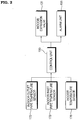
- FIG. 2 is a block diagram of the air conditioner in accordance with an embodiment of the present invention.
- the indoor outlet pipe temperature sensor 172 measures the temperature of the refrigerant discharged from the indoor heat exchanger 120.
- the indoor outlet pipe temperature sensor 172 is installed on the indoor outlet pipe 164.
- the indoor inlet pipe temperature sensor 173 measures the temperature of the refrigerant fed to the indoor heat exchanger 120.
- the indoor inlet pipe temperature sensor 173 is installed on the indoor inlet pipe 163 connecting the indoor heat exchanger 120 and the indoor expansion valve 131.
- the indoor temperature sensor 176 measures the temperature of indoor air.
- the indoor temperature sensor 176 is installed in the indoor unit IU.
- a control unit 190 detects whether or not the indoor expansion valve 131 is malfunctioning based on indoor unit pipe temperatures measured while opening and closing the indoor expansion valve 131.
- the indoor unit pipe temperature is a temperature measured by the indoor outlet pipe temperature sensor 172 or the indoor inlet pipe temperature sensor 173.
- the indoor unit pipe temperature may be the average value of the temperature measured by the indoor outlet pipe temperature sensor 172 and the temperature measured by the indoor inlet pipe temperature sensor 173.
- the control unit 190 detects abnormalities in the indoor unit pipe temperature when the indoor expansion valve 131 is opened and closed. The control unit 190 detects whether or not the indoor expansion valve 131 is malfunctioning by analyzing the variation in the indoor unit pipe temperature as the indoor expansion valve 131 is switched from the open state to the closed state. The control unit 190 then compares the measured variation of the indoor unit pipe temperature with the known variation of the indoor unit pipe temperature in a normal state. Further, the control unit 190 detects whether or not the indoor expansion valve 131 is malfunctioning by analyzing the variation in the indoor unit pipe temperature as the indoor expansion valve 131 is switched from the closed state to the open state. The control unit 190 then compares the measured variation of the indoor unit pipe temperature with the known variation of the indoor unit pipe temperature in the normal state.
- the control unit 190 may detect abnormalities in the difference between the indoor unit pipe temperature and an indoor air temperature when the indoor expansion valve 131 is opened and closed.
- the control unit 190 detects whether or not the indoor expansion pipe 131 is malfunctioning by analyzing the variation in the difference between the indoor unit pipe temperature and the indoor air temperature as the indoor expansion valve 131 is switched from the open state to the closed state.
- the control unit 190 then compares the measured variation of the difference between the indoor unit pipe temperature and the indoor air temperature with the known variation of the difference between the indoor unit pipe temperature and the indoor air temperature in a normal state.
- control unit 190 may initialize the indoor expansion valve 131 because the malfunction may be due to an incorrect determination of the initial open state of the indoor expansion valve 131. The control unit 190 may then again determine whether or not the indoor expansion valve 131 is malfunctioning. The initialization of the indoor expansion valve 131 is as described above.
- the current open state of the indoor expansion valve 131 may be lost by the control unit 190, such as when the power is turned off and then turned on. So while the control unit 90 indicates that the indoor expansion valve 131 is closed, the indoor expansion valve 131 may be substantially open. Thus, the control unit 190 detects that the indoor expansion valve 130 is malfunctioning. Therefore, the control unit 190 initializes the indoor expansion valve and then determines again whether or not the indoor expansion valve 131 is malfunctioning.
- control unit 190 may store an indication that the indoor expansion valve 131 is malfunctioning and/or provide a warning to the user by an alarm unit.
- the alarm unit 193 communicates the fact that the indoor expansion valve 131 is malfunctioning to a user either visually or through sound.
- the alarm unit 193 may inform other systems of the fact that the indoor expansion valve 131 is malfunctioning through a network.
- FIGs. 3(a) to 3(c) are graphs illustrating temperature variations when an indoor expansion valve switches between closed and open during the cooling operation of the air conditioner in accordance with an embodiment of the present invention.
- FIG. 3(a) illustrates the variation of the indoor unit pipe temperature when the indoor expansion valve 131 switches from closed to open during the cooling operation.
- the control unit 190 detects whether or not the indoor expansion valve 131 is operating normally by using a difference of the indoor unit pipe temperatures during a time period T1 and a time period T2.
- the control unit 190 opens the indoor expansion valve 131, a variation in the indoor unit pipe temperature is not greater than the variation during the normal operation of the indoor expansion valve 131. Further, if the indoor expansion valve 131 is initially closed but is not opened due to a malfunction and although the control unit 190 opens the indoor expansion valve 131, the indoor expansion valve 131 is not substantially opened and thus the low-temperature refrigerant does not flow. Therefore, the variation of the indoor unit pipe temperature is not greater than the variation during the normal operation of the indoor expansion valve 131. Therefore, if the difference of the indoor unit pipe temperatures between the time period T1 and the time period T2 is smaller than a predetermined reference value, the control unit 190 determines that the indoor expansion valve 131 is malfunctioning.
- FIG. 3(b) illustrates the variation of the indoor unit pipe temperature when the indoor expansion valve 131 switches from open to closed during the cooling operation.
- the control unit 190 detects whether or not the indoor expansion valve 131 is operating normally by using the difference of the indoor unit pipe temperatures during a time period T1 and a time period T2.
- the control unit 190 closes the indoor expansion valve 131, a variation in the indoor unit pipe temperature is not greater than the variation during the normal operation of the indoor expansion valve 131. Further, if the indoor expansion valve 131 is initially opened but is not closed or is partially closed due to a malfunction and although the control unit 190 closes the indoor expansion valve 131, the indoor expansion valve 131 is not substantially closed and thus the low-temperature refrigerant flows. Therefore, the variation of the indoor unit pipe temperature is not greater than the variation during the normal operation of the indoor expansion valve 131. Therefore, if the difference of the indoor unit pipe temperatures between the time period T1 and the time period T2 is smaller than a predetermining reference value, the control unit 190 determines that the indoor expansion valve 131 is malfunctioning.
- FIG. 3(c) illustrates the variation of the indoor unit pipe temperature when the indoor air temperature when the indoor expansion valve 131 switches from open to closed during the cooling operation.
- the control unit 190 detects whether or not the indoor expansion valve 131 is operating normally by using a difference between the indoor unit pipe temperatures and the indoor air temperature during the time period T1 and the time period T2.
- the indoor expansion valve 131 If the indoor expansion valve 131 is initially partially or completely closed due to a malfunction, the low-temperature refrigerant does not flow. Thus, a difference between the indoor unit pipe temperature and the indoor air temperature is smaller than that during normal operation of the indoor expansion valve 131. Further, if the indoor expansion valve 131 is initially opened but is not closed or is partially closed due to a malfunction and although the control unit 190 closes the indoor expansion valve 131, the indoor expansion valve 131 is not substantially closed and thus the low-temperature refrigerant flows. Thus, a difference between the indoor unit pipe temperature and the indoor air temperature is greater than that during the normal state of the indoor expansion valve 131. Therefore, if the difference of the indoor unit pipe temperature and the indoor air temperature during the time period T1 and the time period T2 is smaller or greater than a predetermined reference value, the control unit 190 determines that the indoor expansion valve 131 is malfunctioning.
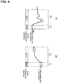
- FIGs. 4(a) and 4(b) are graphs illustrating temperature variations when the indoor expansion valve switches between closed and open during the heating operation of the air conditioner in accordance with an embodiment of the present invention.
- FIG. 4(a) illustrates the variation of the indoor unit pipe temperature when the indoor expansion valve 131 switches from closed to open during the heating operation.
- the control unit 190 detects whether or not the indoor expansion valve 131 is operating normally using a difference of the indoor unit pipe temperatures during a time period T1 and a time period T2.
- the control unit 190 opens the indoor expansion valve 131, a variation in the indoor unit pipe temperature is not greater than the variation during the normal operation of the indoor expansion valve 131. Further, if the indoor expansion valve 131 is initially closed but is not opened due to a malfunction and although the control unit 190 opens the indoor expansion valve 131, the indoor expansion valve 131 is not substantially opened and thus the high-temperature refrigerant does not flow. Therefore, the variation of the indoor unit pipe temperature is not greater than the variation during the normal operation of the indoor expansion valve 131. Therefore, if the difference of the indoor unit pipe temperatures between the time period T1 and the time period T2 is smaller than a predetermined reference value, the control unit 190 determines that the indoor expansion valve 131 is malfunctioning.
- FIG. 4(b) illustrates the variation of the indoor unit pipe temperature when the indoor expansion valve 131 switches from open to closed during the heating operation.
- the control unit 190 detects whether or not the indoor expansion valve 131 is operating normally by using the difference of the indoor unit pipe temperature during a time period T1 and the time period T2.
- the control unit 190 closes the indoor expansion valve 131, a variation in the indoor unit pipe temperature is not greater than the variation during the normal operation of the indoor expansion valve 131. Further, if the indoor expansion valve 131 is initially opened but is not closed or is partially closed due to a malfunction and although the control unit 190 closes the indoor expansion valve 131, the indoor expansion valve 131 is not substantially closed and thus the high-temperature refrigerant flows. Therefore, the variation of the indoor unit pipe temperature is not greater than the variation during the normal operation of the indoor expansion valve 131. Therefore, if the difference of the indoor unit pipe temperatures between the time period T1 and the time period T2 is smaller than a predetermined reference value, the control unit 190 determines that the indoor expansion valve 131 is malfunctioning.
- FIG. 5 is a flow chart illustrating a method for detecting a malfunction of an air conditioner in accordance with an embodiment of the present invention.
- the air conditioner is operated to detect whether or not the indoor expansion valve 131 is malfunctioning (S210).
- the control unit 190 performs a cooling operation or a heating operation and measures the indoor unit pipe temperature while opening and closing the indoor expansion valve 131. A detailed description of the above detection will be described later with reference to FIG. 6 .
- the control unit 190 detects whether or not a variation of the indoor unit pipe temperature is abnormal when the indoor expansion valve 131 is opened and closed. Further, the control unit 190 may detect whether or not a variation of a difference between the indoor unit pipe temperature and the indoor air temperature is abnormal when the indoor expansion valve 131 is opened and closed.
- the indoor expansion valve 131 may be initialized (S230). If the control unit 190 detects an indoor expansion valve 131 malfunction, it is preferable that the control unit 190 initialize the indoor expansion valve 131. Because the control unit 190 may detect that the indoor expansion valve 131 is malfunctioning due to an incorrect determination of the initial open state of the indoor expansion valve 131, the control unit 190 may initialize the indoor expansion valve 131 and then detect again whether or not the indoor expansion valve 131 is malfunctioning.
- the initialization of the indoor expansion valve 131 means initialization of the open state of the indoor expansion valve 131 by completely opening the indoor expansion valve 131 and then completely closing the indoor expansion valve 131. Other various methods of initializing the open state of the indoor expansion valve 131 may be used.
- the air conditioner is operated again to detect whether or not the indoor expansion valve 131 is malfunctioning (S240), and the control unit 190 performs the cooling operation or the heating operation of the air conditioner and measures the indoor unit pipe temperature while opening and closing the indoor expansion valve 131.
- any malfunction of the indoor expansion valve 131 is re-detected (S250), and the control unit 190 detects whether or not a variation of the indoor unit pipe temperature or a variation of a difference between the indoor unit pipe temperature and the indoor air temperature is abnormal when the indoor expansion valve 131 is opened and closed.
- control unit 190 If the control unit 190 detects an indoor expansion valve 131 malfunction, a warning indicating that the indoor expansion valve 131 is malfunctioning is given to the user (S260). If the control unit 190 detects an indoor expansion valve 131 malfunction even after the initialization of the indoor expansion valve 131, the control unit 190 may store an indication that the indoor expansion valve 131 is malfunctioning and/or provide a warning to the user by the alarm unit 193. The alarm unit 193 may display the fact that the indoor expansion valve 131 is malfunctioning to the user visually or through sound.
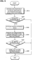
- FIG. 6 is a flow chart illustrating a method for detecting a malfunction of the indoor expansion valve of an air conditioner in accordance with an embodiment of the present invention.
- FIG. 6 illustrates in detail the operation of the air conditioner to detect whether or not the indoor expansion valve 131 is malfunctioning (S210, S240) and the detection whether or not the indoor expansion valve 131 is malfunctioning (S220, S250).
- the air conditioner is started (S310).
- the air conditioner may be in either cooling mode or a heating mode. Further, the air conditioner may be operated to detect whether or not the indoor expansion valve 131 is malfunctioning or may be operated normally to cool or heat an indoor space.
- an indoor unit pipe temperature and an indoor air temperature are measured (S320).
- the control unit 190 measures and tracks the indoor unit pipe temperature and the indoor air temperature.
- the indoor unit pipe temperature is a temperature measured by the indoor outlet pipe temperature sensor 172 or the indoor inlet pipe temperature sensor 173.
- the indoor unit pipe temperature may be the average value of the temperature measured by the indoor outlet pipe temperature sensor 172 and the temperature measured by the indoor inlet pipe temperature sensor 173.
- the indoor air temperature is a temperature of indoor air measured by the indoor temperature sensor 176.
- the indoor expansion valve 131 is opened to the set open state during the cooling operation, and is completely opened during the heating operation. Therefore, in order to detect whether or not the indoor expansion valve 131 is malfunctioning in the cooling operation, the indoor expansion valve 131 may be completely opened.
- the control unit 190 closes the opened indoor expansion valve 131 (S330).
- the indoor outlet pipe temperature sensor 172 or the indoor inlet pipe temperature sensor 173 continuously measures the indoor unit pipe temperature
- the indoor temperature sensor 176 continuously measures the indoor air temperature. Further, the control unit 190 continuously tracks the indoor unit pipe temperature and the indoor air temperature.
- the control unit 190 detects whether or not the indoor unit pipe temperature is abnormal (S340).
- the control unit 190 detects whether or not the indoor unit pipe temperature is abnormal by comparing a variation of the indoor unit pipe temperature during the open state of the indoor expansion valve 131 to the closed state of the indoor expansion valve 131 with that in the normal state.
- control unit 190 detects whether or not a variation of a difference between the indoor unit pipe temperature and the indoor air temperature is abnormal (S350).
- the control unit 190 detects whether or not the variation of the difference between the indoor unit pipe temperature and the indoor air temperature is abnormal by comparing the variation of the difference between the indoor unit pipe temperature and the indoor air temperature during the open state of the indoor expansion valve 131 to the closed state of the indoor expansion valve 131 with that during the normal state.
- the operation S350 may be performed if it is detected that the indoor unit pipe temperature is abnormal during the operation S340. In this case, precision in detecting whether or not the indoor expansion valve 131 is malfunctioning is increased.
- control unit 190 detects that the indoor expansion valve 131 is malfunctioning (S380).
- the control unit 190 opens the indoor expansion valve 131 (S360).
- the indoor outlet pipe temperature sensor 172 or the indoor inlet pipe temperature sensor 173 continuously measures the indoor unit pipe temperature
- the indoor temperature sensor 176 continuously measures the indoor air temperature. Further, the control unit 190 continuously tracks the indoor unit pipe temperature and the indoor air temperature.
- the operation S360 may be performed if the control unit detects that the variation of the difference between the indoor unit pipe temperature and the indoor air temperature is abnormal during operation S350. In this case, the precision in detecting whether or not the indoor expansion valve 131 is malfunctioning is increased.
- control unit 190 detects that the variation of the difference between the indoor unit pipe temperature and the indoor air temperature is abnormal, the control unit 190 detects that the indoor expansion valve 131 is malfunctioning (S380).
- the control unit 190 detects whether or not the indoor unit pipe temperature is abnormal (S370).
- the control unit 190 detects whether or not the indoor unit pipe temperature is abnormal by comparing a variation of the indoor unit pipe temperature during the closed state of the indoor expansion valve 131 to the open state of the indoor expansion valve 131 with that during the normal state.
- control unit 190 detects that the indoor unit pipe temperature is abnormal, the control unit 190 detects that the indoor expansion valve 131 is malfunctioning (S380).
Description
- The present invention relates to an air conditioner and a method for detecting a malfunction thereof, and more particularly to an air conditioner, which automatically detects a malfunction, and a method for automatically detecting a malfunction of the air conditioner.
- In general, air conditioners are apparatuses that maintain air in a designated space at a temperature and humidity level that is comfortable to humans. These air conditioners absorb heat in a designated space, or emit heat into the space, and thus maintain temperature and humidity of the space at suitable levels. Each air conditioner has an indoor unit, which absorbs heat in a designated space or emits heat into the space.
- Various devices may be included in the indoor unit. Particularly, an indoor expansion valve to control refrigerant flow may be included in the indoor unit. Conventionally, to detect a malfunction of the indoor expansion valve, a technician monitors the operating state of the indoor unit.
EP 1 750 073 A2 describes a pipe inspection method and a pipe-inspection operation method of a multi-air conditioner. Herein, indoor heat exchangers are adapted to serve as condensers and outdoor heat exchanger is adapted to serve as an evaporator. When a pipe inspection signal for heating is inputted, a fan of an outdoor unit and a 4-way valve thereof are initialized, the fan of the outdoor unit and fans of indoor units are activated, and a compressor is operated at a predetermined frequency (40Hz). At this time, expansion valves are fully open to set a reference point for valve opening control. That is, the valve opening degree of an expansion valve is controlled in 500 steps from a fully open position of the expansion valve to a fully closed position thereof, and the reference point is set corresponding to the fully open position. After the reference point for control of the valve opening is set, the multi-air conditioner system is activated to raise temperatures of the indoor units to a certain temperature. At this time, the expansion valves are opened at a small valve opening degree (80-step) to rapidly raise the temperatures of the indoor units. This is because a temperature difference between before and after an expansion valve becomes larger with a smaller valve opening degree of the expansion valve. Afterwards, for pipe inspection, the expansion valves are opened at a valve opening degree of 120 step, the multi-air conditioner system is operated for 5 minutes, and then temperatures of the respective indoor units are measured. One of the expansion valves under inspection is fully closed, and the temperatures of the respective indoor units are measured again. If the expansion valve under inspection is closed, the temperature of an indoor unit connected with the expansion valve under inspection drops. This temperature change is utilized to inspect normality of a pipe and match the pipe to the address of an indoor unit. If there exists an indoor unit whose temperature difference between before and after the closure of the expansion valve under inspection is greater than or equal to a predetermined value and whose temperature is the lowest among those of the indoor units, the indoor unit is selected as one being connected with the expansion valve under inspection, and the above operations are repeated to continue pipe inspection by manipulating a next expansion valve. If there is no indoor unit whose temperature difference between before and after the closure of the expansion valve under inspection is greater than or equal to the predetermined value and whose temperature is the lowest among those of the indoor units, the expansion valve under inspection is determined to have malfunctioned and this result is registered, and the above operations are repeated to continue the pipe inspection.
JP 2000-274896 A
US 5,689,963 A describes diagnostics for heating and cooling system. Herein, a stuck-closed expansion valve/lost refrigerant charge detection procedure could be performed in a heating or cooling mode. If a differential discharge temperature is less than a temperature difference limit or the expansion valve is not in the fully-open setting control proceeds. If the low pressure cutout switch is triggered, the system determines if the low pressure cut out switch malfunction is set. If the low pressure cut out switch malfunction is set, the stuck-closed expansion valve/low refrigerant charge detection procedure ends. If not, control proceeds where the system attempts to unstick the expansion valve by opening the expansion valve a predetermined number open steps (for example 10 steps), by closing the expansion valve the same number of steps and by repeating the procedure a predetermined number of times (for example ten times). Control then proceeds where the detection procedure determines if the low pressure cutout has been reset (i.e. has the inlet pressure risen above the reset pressure limit). If not, the malfunction display is cleared and control continues.
JP 2007-333219 A - It is an object of the present invention to provide an air conditioner, which automates detection of a malfunction of an indoor expansion valve, conventionally trusted only to an expert, and a method for detecting a malfunction of the air conditioner.
- Another object of the present invention is to provide an air conditioner having a high precision in detecting a malfunction an indoor expansion valve and a method for detecting a malfunction of the air conditioner.
- Still another object of the present invention is to provide an air conditioner that is capable of detecting a malfunction of an indoor expansion valve in both cooling and heating operations, and a method for detecting a malfunction of the air conditioner.
- These objects are solved by the method according to claim 1 and the air conditioner according to claim 7. Further advantageous embodiments and refinements of the present invention are described in the respective sub-claims.
- There is provided a method for detecting a malfunction of an air conditioner according to an exemplary embodiment of the present invention, including measuring an indoor unit pipe temperature around an indoor heat exchanger during operation of the air conditioner; actuating an indoor expansion valve connected to the indoor heat exchanger to a first state; and detecting whether or not a variation of the indoor unit pipe temperature is abnormal by measuring the indoor unit pipe temperature after actuating the indoor expansion valve to the first state.
- There is provided an air conditioner according to an exemplary embodiment of the present invention, including an indoor heat exchanger including a refrigerant that exchanges heat with indoor air; an indoor expansion valve connected to the indoor heat exchanger to control refrigerant flow; and a control unit that detects whether or not the indoor expansion valve is malfunctioning by measuring an indoor unit pipe temperature to the indoor heat exchanger while actuating the indoor expansion valve to a first state.
- The accompanying drawings, which are included to provide a further understanding of the invention and are incorporated in and constitute a part of this specification, illustrate embodiments of the invention and together with the description serve to explain the principles of the invention.
-
FIG. 1 is a schematic view of an air conditioner in accordance with one embodiment of the present invention; -
FIG. 2 is a block diagram of the air conditioner in accordance with the embodiment of the present invention; -
FIGs. 3(a) to 3(c) are graphs illustrating temperature variations caused by the opening and closing of an indoor expansion valve of the air conditioner during a cooling operation in accordance with an embodiment of the present invention; -
FIGs. 4(a) and 4(b) are graphs illustrating temperature variations caused by the opening and closing of the indoor expansion valve of the air conditioner during a heating operation in accordance with an embodiment of the present invention; -
FIG. 5 is a flow chart illustrating a method for detecting a malfunction of an air conditioner in accordance with an embodiment of the present invention; and -
FIG. 6 is a flow chart illustrating a method for detecting a malfunction of the indoor expansion valve of the air conditioner in accordance with an embodiment of the present invention. - The advantages and features of the present invention, and the way of attaining them, will become apparent with reference to embodiments described below in conjunction with the accompanying drawings. However, the present invention is not limited to the embodiments disclosed below and will be embodied in a variety of different forms; rather, these embodiments are provided so that this disclosure will be thorough and complete, and will fully convey the scope of the present invention to those skilled in the art, and the scope of the present invention will be defined by the appended claims. Like reference numerals refer to like elements throughout the specification.
- An air conditioner and a method for detecting a malfunction of the air conditioner in accordance with embodiments of the present invention will hereinafter be described in detail with reference to the accompanying drawings.
-
FIG. 1 is a schematic view of an air conditioner in accordance with an embodiment of the present invention. - The air conditioner may include an outdoor unit OU and an indoor unit IU.
- The outdoor unit OU includes a
compressor 110, anoutdoor heat exchanger 140, anoutdoor expansion valve 132, and asupercooler 180. The air conditioner may include one outdoor unit OU or a plurality of outdoor units OU. - The
compressor 110 compresses an incoming refrigerant from a low-temperature and low-pressure state into a high-temperature and high-pressure state. Thecompressor 110 may include various structures, and may employ an inverter-type compressor or a constant speed compressor. Adischarge temperature sensor 171 and adischarge pressure sensor 151 are installed on adischarge pipe 161 of thecompressor 110. Further, asuction temperature sensor 175 and asuction pressure sensor 154 are installed on asuction pipe 162 of thecompressor 110. - Although the outdoor unit OU of this embodiment includes one
compressor 110, the present invention is not limited thereto. That is, the outdoor unit OU may include a plurality of compressors, and may include an inverter-type compressor and a constant speed compressor simultaneously. - In order to prevent refrigerant in a liquid state from being fed into the
compressor 110, anaccumulator 187 may be installed on thesuction pipe 162 of thecompressor 110. Further, anoil separator 113 may be installed on thedischarge pipe 161 of thecompressor 110 so as to collect oil from the refrigerant discharged from thecompressor 110. - A four-
way valve 160 is a flow switching valve to switch between cooling and heating operations. The four-way valve 160 guides the refrigerant, compressed by thecompressor 110, to theoutdoor heat exchanger 140 during the cooling operation, and to anindoor heat exchanger 120 during the heating operation. The four-way valve 160 is in an A state in the cooling operation, and is in a B state in the heating operation. The arrows indicating the refrigerant flow inFIG. 1 illustrate a cooling operation with the four-way valve 160 in the A state. - The
outdoor heat exchanger 140 is disposed in an outdoor space, and the refrigerant passing through theoutdoor heat exchanger 140 exchanges heat with outdoor air. Theoutdoor heat exchanger 140 serves as a condenser in the cooling operation and serves as an evaporator in the heating operation. - The
outdoor expansion valve 132 controls the incoming refrigerant flow in the heating operation, and is installed on aninlet pipe 166 connecting a liquidrefrigerant pipe 165 and theoutdoor heat exchanger 140. Further, afirst bypass pipe 167 to allow the refrigerant to bypass theoutdoor expansion valve 132 is installed on theinlet pipe 166, and acheck valve 133 is installed on thefirst bypass pipe 167 to allow refrigerant to only flow in one direction. - The
check valve 133 causes the refrigerant to flow from theoutdoor heat exchanger 140 to the indoor unit IU in the cooling operation, but shuts off the flow of the refrigerant in the heating operation. - The
supercooler 180 includes asupercooling heat exchanger 184, asecond bypass pipe 181, asupercooling expansion valve 182, and adischarge pipe 185. The supercoolingheat exchanger 184 is disposed on theinlet pipe 166. In the cooling operation, thesecond bypass pipe 181 serves to cause the refrigerant discharged from the supercoolingheat exchanger 184 to be fed into thesupercooling expansion valve 182. - The supercooling
expansion valve 182 is disposed on thesecond bypass pipe 181. The supercoolingexpansion valve 182 controls the refrigerant flow in a liquid state fed into thesecond bypass pipe 181 to lower the pressure and temperature of the refrigerant, and then feeds the refrigerant in the low-pressure and low-temperature state into thesupercooling heat exchanger 184. The supercoolingexpansion valve 182 may employ various types of valves, but the present embodiment employs a linear expansion valve. A supercoolingtemperature sensor 183 to sense the temperature of the refrigerant controlled by the supercoolingexpansion valve 182 may be installed on thesecond bypass pipe 181. - During the cooling operation, the condensed refrigerant passing through the
outdoor heat exchanger 140 is supercooled by exchanging heat with the refrigerant in the low-temperature state fed through thesecond bypass pipe 181 in thesupercooling heat exchanger 184, and then is fed to the indoor unit IU. - The refrigerant passing through the
second bypass pipe 181 is fed to theaccumulator 187 through thedischarge pipe 185, after undergoing heat-exchange in thesupercooling heat exchanger 184. A dischargepipe temperature sensor 178 to measure the temperature of the refrigerant fed to theaccumulator 187 is installed on thedischarge pipe 185. - A liquid
pipe temperature sensor 174 and a liquidpipe pressure sensor 156 are installed on theliquid pipe 165 connecting thesupercooler 180 and the indoor unit IU. - In an embodiment of the air conditioner in accordance with the present invention, the indoor unit IU may include an
indoor heat exchanger 120, an indoor air blower 125, and anindoor expansion valve 131. The air conditioner may include one indoor unit IU or a plurality of indoor units IU. - The
indoor heat exchanger 120 is disposed in an indoor space, and the refrigerant passing through theindoor heat exchanger 120 exchanges heat with indoor air. Theindoor heat exchanger 120 serves as an evaporator in the cooling operation, and serves as a condenser in the heating operation. Anindoor temperature sensor 176 to measure an indoor temperature is installed in theindoor heat exchanger 120. - The
indoor expansion valve 131 controls the incoming refrigerant flow in the cooling operation. Theindoor expansion valve 131 is installed on anindoor inlet pipe 163 of the indoor unit IU. Theindoor expansion valve 131 may employ various types of valves, but the present embodiment employs a linear expansion valve. - Preferably, the
indoor expansion valve 131 is opened to a set position that restricts the flow during in the cooling operation and is completely opened during the heating operation. Theindoor expansion valve 131 may be closed or opened in order to detect a malfunction during the cooling operation or the heating operation. Here, the closing of theindoor expansion valve 131 does not mean a complete physical closing, but means a position of theindoor expansion valve 131 such that the refrigerant does not flow through theindoor expansion valve 131. - A malfunction of the
indoor expansion valve 131 may be detected if the initial open state of theindoor expansion valve 131 is incorrectly determined. Therefore, when anindoor expansion valve 131 malfunction is detected, the indoor expansion valve 31 may be initialized. Theindoor expansion valve 131 is initialized by completely opening theindoor expansion valve 131 and then completely closing theindoor expansion valve 131. Other various methods of initializing the open state of theindoor expansion valve 131 may also be used. - An indoor inlet
pipe temperature sensor 173 may be installed on theindoor inlet pipe 163. The indoor inletpipe temperature sensor 173 may be installed between theindoor heat exchanger 120 and theindoor expansion valve 131. Further, an indoor outletpipe temperature sensor 172 may be installed on anindoor outlet pipe 164. - The flow of the refrigerant during the cooling operation of the above-described air conditioner is as follows.
- The refrigerant in a high-temperature and high-pressure vapor state discharged from the
compressor 110 is fed into theoutdoor heat exchanger 140 via the four-way valve 160. In theoutdoor heat exchanger 140, the refrigerant exchanges heat with outdoor air, thus being condensed. The refrigerant discharged from theoutdoor heat exchanger 140 is fed to thesupercooler 180 through the completely openoutdoor expansion valve 132 and thebypass pipe 133. The refrigerant fed to thesupercooler 180 is supercooled by the supercoolingheat exchanger 184, and then is fed to the indoor unit IU. - A part of the refrigerant supercooled by the supercooling
heat exchanger 184 is controlled by the supercoolingexpansion valve 182. A part of the refrigerant supercooled by the supercoolingheat exchanger 184 is fed to theaccumulator 187. - The refrigerant fed to the indoor unit IU is controlled by the
indoor expansion valve 131 that is open to a set open state, and the refrigerant then exchanges heat with indoor air in theindoor heat exchanger 120 by being evaporated. The evaporated refrigerant is then fed into thecompressor 110 via the four-way valve 160 and theaccumulator 187. - The flow of the refrigerant during the heating operation of the above-described air conditioner is as follows.
- The refrigerant in a high-temperature and high-pressure vapor state discharged from the
compressor 110 is fed into the indoor unit IU via the four-way valve 160. Theindoor expansion valve 131 of the indoor unit IU is completely open. Therefore, the refrigerant fed from the indoor unit IU is controlled by theoutdoor expansion valve 132, and then exchanges heat with outdoor air in theoutdoor heat exchanger 140 by being evaporated. The evaporated refrigerant is then fed into thesuction pipe 162 of thecompressor 110 via the four-way valve 160 and theaccumulator 187. -
FIG. 2 is a block diagram of the air conditioner in accordance with an embodiment of the present invention. - The indoor outlet
pipe temperature sensor 172 measures the temperature of the refrigerant discharged from theindoor heat exchanger 120. The indoor outletpipe temperature sensor 172 is installed on theindoor outlet pipe 164. - The indoor inlet
pipe temperature sensor 173 measures the temperature of the refrigerant fed to theindoor heat exchanger 120. The indoor inletpipe temperature sensor 173 is installed on theindoor inlet pipe 163 connecting theindoor heat exchanger 120 and theindoor expansion valve 131. - The
indoor temperature sensor 176 measures the temperature of indoor air. Theindoor temperature sensor 176 is installed in the indoor unit IU. - A
control unit 190 detects whether or not theindoor expansion valve 131 is malfunctioning based on indoor unit pipe temperatures measured while opening and closing theindoor expansion valve 131. The indoor unit pipe temperature is a temperature measured by the indoor outletpipe temperature sensor 172 or the indoor inletpipe temperature sensor 173. The indoor unit pipe temperature may be the average value of the temperature measured by the indoor outletpipe temperature sensor 172 and the temperature measured by the indoor inletpipe temperature sensor 173. - The
control unit 190 detects abnormalities in the indoor unit pipe temperature when theindoor expansion valve 131 is opened and closed. Thecontrol unit 190 detects whether or not theindoor expansion valve 131 is malfunctioning by analyzing the variation in the indoor unit pipe temperature as theindoor expansion valve 131 is switched from the open state to the closed state. Thecontrol unit 190 then compares the measured variation of the indoor unit pipe temperature with the known variation of the indoor unit pipe temperature in a normal state. Further, thecontrol unit 190 detects whether or not theindoor expansion valve 131 is malfunctioning by analyzing the variation in the indoor unit pipe temperature as theindoor expansion valve 131 is switched from the closed state to the open state. Thecontrol unit 190 then compares the measured variation of the indoor unit pipe temperature with the known variation of the indoor unit pipe temperature in the normal state. - The
control unit 190 may detect abnormalities in the difference between the indoor unit pipe temperature and an indoor air temperature when theindoor expansion valve 131 is opened and closed. Thecontrol unit 190 detects whether or not theindoor expansion pipe 131 is malfunctioning by analyzing the variation in the difference between the indoor unit pipe temperature and the indoor air temperature as theindoor expansion valve 131 is switched from the open state to the closed state. Thecontrol unit 190 then compares the measured variation of the difference between the indoor unit pipe temperature and the indoor air temperature with the known variation of the difference between the indoor unit pipe temperature and the indoor air temperature in a normal state. - If the
control unit 190 detects a malfunction of theindoor expansion valve 131, thecontrol unit 190 may initialize theindoor expansion valve 131 because the malfunction may be due to an incorrect determination of the initial open state of theindoor expansion valve 131. Thecontrol unit 190 may then again determine whether or not theindoor expansion valve 131 is malfunctioning. The initialization of theindoor expansion valve 131 is as described above. - The current open state of the
indoor expansion valve 131 may be lost by thecontrol unit 190, such as when the power is turned off and then turned on. So while the control unit 90 indicates that theindoor expansion valve 131 is closed, theindoor expansion valve 131 may be substantially open. Thus, thecontrol unit 190 detects that the indoor expansion valve 130 is malfunctioning. Therefore, thecontrol unit 190 initializes the indoor expansion valve and then determines again whether or not theindoor expansion valve 131 is malfunctioning. - If the
control unit 190 detects that theindoor expansion valve 131 is malfunctioning after the initialization of theindoor expansion valve 131, thecontrol unit 190 may store an indication that theindoor expansion valve 131 is malfunctioning and/or provide a warning to the user by an alarm unit. - If the
control unit 190 determines that theindoor expansion valve 131 is malfunctioning, thealarm unit 193 communicates the fact that theindoor expansion valve 131 is malfunctioning to a user either visually or through sound. Thealarm unit 193 may inform other systems of the fact that theindoor expansion valve 131 is malfunctioning through a network. -
FIGs. 3(a) to 3(c) are graphs illustrating temperature variations when an indoor expansion valve switches between closed and open during the cooling operation of the air conditioner in accordance with an embodiment of the present invention. -
FIG. 3(a) illustrates the variation of the indoor unit pipe temperature when theindoor expansion valve 131 switches from closed to open during the cooling operation. Thecontrol unit 190 detects whether or not theindoor expansion valve 131 is operating normally by using a difference of the indoor unit pipe temperatures during a time period T1 and a time period T2. - If the
indoor expansion valve 131 is initially partially or completely open due to a malfunction, a low-temperature refrigerant flows. Thus, although thecontrol unit 190 opens theindoor expansion valve 131, a variation in the indoor unit pipe temperature is not greater than the variation during the normal operation of theindoor expansion valve 131. Further, if theindoor expansion valve 131 is initially closed but is not opened due to a malfunction and although thecontrol unit 190 opens theindoor expansion valve 131, theindoor expansion valve 131 is not substantially opened and thus the low-temperature refrigerant does not flow. Therefore, the variation of the indoor unit pipe temperature is not greater than the variation during the normal operation of theindoor expansion valve 131. Therefore, if the difference of the indoor unit pipe temperatures between the time period T1 and the time period T2 is smaller than a predetermined reference value, thecontrol unit 190 determines that theindoor expansion valve 131 is malfunctioning. -
FIG. 3(b) illustrates the variation of the indoor unit pipe temperature when theindoor expansion valve 131 switches from open to closed during the cooling operation. Thecontrol unit 190 detects whether or not theindoor expansion valve 131 is operating normally by using the difference of the indoor unit pipe temperatures during a time period T1 and a time period T2. - If the
indoor expansion valve 131 is initially partially or completely closed due to a malfunction, the low-temperature refrigerant does not flow. Thus, although thecontrol unit 190 closes theindoor expansion valve 131, a variation in the indoor unit pipe temperature is not greater than the variation during the normal operation of theindoor expansion valve 131. Further, if theindoor expansion valve 131 is initially opened but is not closed or is partially closed due to a malfunction and although thecontrol unit 190 closes theindoor expansion valve 131, theindoor expansion valve 131 is not substantially closed and thus the low-temperature refrigerant flows. Therefore, the variation of the indoor unit pipe temperature is not greater than the variation during the normal operation of theindoor expansion valve 131. Therefore, if the difference of the indoor unit pipe temperatures between the time period T1 and the time period T2 is smaller than a predetermining reference value, thecontrol unit 190 determines that theindoor expansion valve 131 is malfunctioning. -
FIG. 3(c) illustrates the variation of the indoor unit pipe temperature when the indoor air temperature when theindoor expansion valve 131 switches from open to closed during the cooling operation. Thecontrol unit 190 detects whether or not theindoor expansion valve 131 is operating normally by using a difference between the indoor unit pipe temperatures and the indoor air temperature during the time period T1 and the time period T2. - If the
indoor expansion valve 131 is initially partially or completely closed due to a malfunction, the low-temperature refrigerant does not flow. Thus, a difference between the indoor unit pipe temperature and the indoor air temperature is smaller than that during normal operation of theindoor expansion valve 131. Further, if theindoor expansion valve 131 is initially opened but is not closed or is partially closed due to a malfunction and although thecontrol unit 190 closes theindoor expansion valve 131, theindoor expansion valve 131 is not substantially closed and thus the low-temperature refrigerant flows. Thus, a difference between the indoor unit pipe temperature and the indoor air temperature is greater than that during the normal state of theindoor expansion valve 131. Therefore, if the difference of the indoor unit pipe temperature and the indoor air temperature during the time period T1 and the time period T2 is smaller or greater than a predetermined reference value, thecontrol unit 190 determines that theindoor expansion valve 131 is malfunctioning. -
FIGs. 4(a) and 4(b) are graphs illustrating temperature variations when the indoor expansion valve switches between closed and open during the heating operation of the air conditioner in accordance with an embodiment of the present invention. -
FIG. 4(a) illustrates the variation of the indoor unit pipe temperature when theindoor expansion valve 131 switches from closed to open during the heating operation. Thecontrol unit 190 detects whether or not theindoor expansion valve 131 is operating normally using a difference of the indoor unit pipe temperatures during a time period T1 and a time period T2. - If the
indoor expansion valve 131 is initially partially or completely open due to a malfunction, a high-temperature refrigerant flows. Thus, although thecontrol unit 190 opens theindoor expansion valve 131, a variation in the indoor unit pipe temperature is not greater than the variation during the normal operation of theindoor expansion valve 131. Further, if theindoor expansion valve 131 is initially closed but is not opened due to a malfunction and although thecontrol unit 190 opens theindoor expansion valve 131, theindoor expansion valve 131 is not substantially opened and thus the high-temperature refrigerant does not flow. Therefore, the variation of the indoor unit pipe temperature is not greater than the variation during the normal operation of theindoor expansion valve 131. Therefore, if the difference of the indoor unit pipe temperatures between the time period T1 and the time period T2 is smaller than a predetermined reference value, thecontrol unit 190 determines that theindoor expansion valve 131 is malfunctioning. -
FIG. 4(b) illustrates the variation of the indoor unit pipe temperature when theindoor expansion valve 131 switches from open to closed during the heating operation. Thecontrol unit 190 detects whether or not theindoor expansion valve 131 is operating normally by using the difference of the indoor unit pipe temperature during a time period T1 and the time period T2. - If the
indoor expansion valve 131 is initially partially or completely closed due to a malfunction, the high-temperature refrigerant does not flow. Thus, although thecontrol unit 190 closes theindoor expansion valve 131, a variation in the indoor unit pipe temperature is not greater than the variation during the normal operation of theindoor expansion valve 131. Further, if theindoor expansion valve 131 is initially opened but is not closed or is partially closed due to a malfunction and although thecontrol unit 190 closes theindoor expansion valve 131, theindoor expansion valve 131 is not substantially closed and thus the high-temperature refrigerant flows. Therefore, the variation of the indoor unit pipe temperature is not greater than the variation during the normal operation of theindoor expansion valve 131. Therefore, if the difference of the indoor unit pipe temperatures between the time period T1 and the time period T2 is smaller than a predetermined reference value, thecontrol unit 190 determines that theindoor expansion valve 131 is malfunctioning. -
FIG. 5 is a flow chart illustrating a method for detecting a malfunction of an air conditioner in accordance with an embodiment of the present invention. - First, the air conditioner is operated to detect whether or not the
indoor expansion valve 131 is malfunctioning (S210). In order to detect whether or not theindoor expansion valve 131 is malfunctioning, thecontrol unit 190 performs a cooling operation or a heating operation and measures the indoor unit pipe temperature while opening and closing theindoor expansion valve 131. A detailed description of the above detection will be described later with reference toFIG. 6 . - Thereafter, any malfunction of the
indoor expansion valve 131 is detected (S220). Thecontrol unit 190 detects whether or not a variation of the indoor unit pipe temperature is abnormal when theindoor expansion valve 131 is opened and closed. Further, thecontrol unit 190 may detect whether or not a variation of a difference between the indoor unit pipe temperature and the indoor air temperature is abnormal when theindoor expansion valve 131 is opened and closed. - If the
control unit 190 detects anindoor expansion valve 131 malfunction, theindoor expansion valve 131 may be initialized (S230). If thecontrol unit 190 detects anindoor expansion valve 131 malfunction, it is preferable that thecontrol unit 190 initialize theindoor expansion valve 131. Because thecontrol unit 190 may detect that theindoor expansion valve 131 is malfunctioning due to an incorrect determination of the initial open state of theindoor expansion valve 131, thecontrol unit 190 may initialize theindoor expansion valve 131 and then detect again whether or not theindoor expansion valve 131 is malfunctioning. The initialization of theindoor expansion valve 131 means initialization of the open state of theindoor expansion valve 131 by completely opening theindoor expansion valve 131 and then completely closing theindoor expansion valve 131. Other various methods of initializing the open state of theindoor expansion valve 131 may be used. - Next, the air conditioner is operated again to detect whether or not the
indoor expansion valve 131 is malfunctioning (S240), and thecontrol unit 190 performs the cooling operation or the heating operation of the air conditioner and measures the indoor unit pipe temperature while opening and closing theindoor expansion valve 131. - Thereafter, any malfunction of the
indoor expansion valve 131 is re-detected (S250), and thecontrol unit 190 detects whether or not a variation of the indoor unit pipe temperature or a variation of a difference between the indoor unit pipe temperature and the indoor air temperature is abnormal when theindoor expansion valve 131 is opened and closed. - If the
control unit 190 detects anindoor expansion valve 131 malfunction, a warning indicating that theindoor expansion valve 131 is malfunctioning is given to the user (S260). If thecontrol unit 190 detects anindoor expansion valve 131 malfunction even after the initialization of theindoor expansion valve 131, thecontrol unit 190 may store an indication that theindoor expansion valve 131 is malfunctioning and/or provide a warning to the user by thealarm unit 193. Thealarm unit 193 may display the fact that theindoor expansion valve 131 is malfunctioning to the user visually or through sound. -
FIG. 6 is a flow chart illustrating a method for detecting a malfunction of the indoor expansion valve of an air conditioner in accordance with an embodiment of the present invention. -
FIG. 6 illustrates in detail the operation of the air conditioner to detect whether or not theindoor expansion valve 131 is malfunctioning (S210, S240) and the detection whether or not theindoor expansion valve 131 is malfunctioning (S220, S250). - First, the air conditioner is started (S310). The air conditioner may be in either cooling mode or a heating mode. Further, the air conditioner may be operated to detect whether or not the
indoor expansion valve 131 is malfunctioning or may be operated normally to cool or heat an indoor space. - Next, an indoor unit pipe temperature and an indoor air temperature are measured (S320). In order to detect whether or not the
indoor expansion valve 131 is malfunctioning, thecontrol unit 190 measures and tracks the indoor unit pipe temperature and the indoor air temperature. - The indoor unit pipe temperature is a temperature measured by the indoor outlet
pipe temperature sensor 172 or the indoor inletpipe temperature sensor 173. The indoor unit pipe temperature may be the average value of the temperature measured by the indoor outletpipe temperature sensor 172 and the temperature measured by the indoor inletpipe temperature sensor 173. The indoor air temperature is a temperature of indoor air measured by theindoor temperature sensor 176. - The
indoor expansion valve 131 is opened to the set open state during the cooling operation, and is completely opened during the heating operation. Therefore, in order to detect whether or not theindoor expansion valve 131 is malfunctioning in the cooling operation, theindoor expansion valve 131 may be completely opened. - The
control unit 190 closes the opened indoor expansion valve 131 (S330). When thecontrol unit 190 closes theindoor expansion valve 131, the indoor outletpipe temperature sensor 172 or the indoor inletpipe temperature sensor 173 continuously measures the indoor unit pipe temperature, and theindoor temperature sensor 176 continuously measures the indoor air temperature. Further, thecontrol unit 190 continuously tracks the indoor unit pipe temperature and the indoor air temperature. - The
control unit 190 detects whether or not the indoor unit pipe temperature is abnormal (S340). Thecontrol unit 190 detects whether or not the indoor unit pipe temperature is abnormal by comparing a variation of the indoor unit pipe temperature during the open state of theindoor expansion valve 131 to the closed state of theindoor expansion valve 131 with that in the normal state. - If the control unit detects that the indoor unit pipe temperature is not abnormal, the
control unit 190 detects whether or not a variation of a difference between the indoor unit pipe temperature and the indoor air temperature is abnormal (S350). Thecontrol unit 190 detects whether or not the variation of the difference between the indoor unit pipe temperature and the indoor air temperature is abnormal by comparing the variation of the difference between the indoor unit pipe temperature and the indoor air temperature during the open state of theindoor expansion valve 131 to the closed state of theindoor expansion valve 131 with that during the normal state. - The operation S350 may be performed if it is detected that the indoor unit pipe temperature is abnormal during the operation S340. In this case, precision in detecting whether or not the
indoor expansion valve 131 is malfunctioning is increased. - If the control unit detects that the indoor unit pipe temperature is abnormal, the
control unit 190 detects that theindoor expansion valve 131 is malfunctioning (S380). - If the control unit detects that the variation of the difference between the indoor unit pipe temperature and the indoor air temperature is not abnormal, the
control unit 190 opens the indoor expansion valve 131 (S360). When thecontrol unit 190 opens theindoor expansion valve 131, the indoor outletpipe temperature sensor 172 or the indoor inletpipe temperature sensor 173 continuously measures the indoor unit pipe temperature, and theindoor temperature sensor 176 continuously measures the indoor air temperature. Further, thecontrol unit 190 continuously tracks the indoor unit pipe temperature and the indoor air temperature. - The operation S360 may be performed if the control unit detects that the variation of the difference between the indoor unit pipe temperature and the indoor air temperature is abnormal during operation S350. In this case, the precision in detecting whether or not the
indoor expansion valve 131 is malfunctioning is increased. - If the
control unit 190 detects that the variation of the difference between the indoor unit pipe temperature and the indoor air temperature is abnormal, thecontrol unit 190 detects that theindoor expansion valve 131 is malfunctioning (S380). - The
control unit 190 detects whether or not the indoor unit pipe temperature is abnormal (S370). Thecontrol unit 190 detects whether or not the indoor unit pipe temperature is abnormal by comparing a variation of the indoor unit pipe temperature during the closed state of theindoor expansion valve 131 to the open state of theindoor expansion valve 131 with that during the normal state. - If the
control unit 190 detects that the indoor unit pipe temperature is abnormal, thecontrol unit 190 detects that theindoor expansion valve 131 is malfunctioning (S380). - According to the air conditioner and method for detecting a malfunction of the air conditioner of the present invention, one or more effects as follows may be achieved.
- First, detection of a malfunction of an indoor expansion valve, conventionally trusted only to an expert, is automated, thereby reducing wasted time and manpower.
- Second, the precision in detecting a malfunction of the indoor expansion valve, which conventionally relies on the proficiency of the expert, is improved.
- Third, detection of a malfunction of the indoor expansion valve is possible in both cooling and heating operations.
- Fourth, a possibility of detecting that the indoor expansion valve is malfunctioning due to incorrect recognition of the initial open state of the indoor expansion valve is eliminated, thereby improving the precision in detection of a malfunction of the indoor expansion valve.
- Fifth, the possibility of identifying a normal indoor unit as a malfunctioning indoor unit is reduced.
- The effects of the present invention are not limited to the above-mentioned effects, and other effects not mentioned above can be clearly understood from the definitions in the claims by one skilled in the art.
Claims (7)
- A method for detecting a malfunction of an air conditioner comprising:measuring (S210) an indoor unit pipe temperature around an indoor heat exchanger (120) during operation of the air conditioner;actuating (S210) an indoor expansion valve (131) connected to the indoor heat exchanger (120) to a first state; anddetecting (S220) whether or not a variation of the indoor unit pipe temperature is abnormal by measuring the indoor unit pipe temperature after actuating the indoor expansion valve (131) to the first state;initializing (S230) the indoor expansion valve, if it is detected that the variation of the indoor unit pipe temperature is abnormal;measuring the indoor unit pipe temperature when the air conditioner is operating after the initialization of the indoor expansion valve (131);actuating the indoor expansion valve to the first state; anddetecting (S250) whether or not a variation of the indoor unit pipe temperature is abnormal by measuring the indoor unit pipe temperature after actuating the indoor expansion valve (131) to the first state,wherein the initializing the indoor expansion valve (131) comprises, completely opening the indoor expansion valve (131), and then completely closing the indoor expansion valve (131).
- The method according to claim 1, wherein the indoor unit pipe temperature is a temperature of an indoor inlet pipe (163) of the indoor heat exchanger (120).
- The method according to claim 1, further comprising:measuring an indoor air temperature;calculating a temperature difference between the indoor unit pipe (163) and indoor air; anddetecting whether or not a variation the temperature difference is abnormal by measuring the indoor unit pipe temperature after actuating the indoor expansion valve (131) to the first state.
- The method according to claim 1, wherein measuring the indoor unit pipe temperature includes measuring both the temperature of an indoor inlet pipe (163) and of an indoor outlet pipe (169) of the heat exchanger (120).
- The method according to claim 1, further comprising:actuating the indoor expansion valve (131) to a second state; anddetecting whether or not a variation of the indoor unit pipe temperature is abnormal by measuring the indoor unit pipe temperature after the opening of the indoor expansion valve (131).
- The method according to claim 1, further comprising warning (S260) that the indoor expansion valve (131) is malfunctioning, if it is detected that the variation of the indoor unit pipe temperature is abnormal.
- An air conditioner comprising:an indoor heat exchanger (120) including a refrigerant that exchanges heat with indoor air;an indoor expansion valve (131) connected to the indoor heat exchanger (120) to control refrigerant flow;an indoor inlet pipe temperature sensor (173) installed between the indoor heat exchanger (120) and the indoor expansion valve (131; an indoor outlet pipe temperature sensor (172) installed on an indoor outlet pipe (164) of the indoor heat exchanger (120);and a control unit (190) being adapted to execute the method according to any one of the preceding claims.
Applications Claiming Priority (2)
| Application Number | Priority Date | Filing Date | Title |
|---|---|---|---|
| KR1020090000924A KR20100081620A (en) | 2009-01-06 | 2009-01-06 | Air conditioner and method for detecting error of air conditioner |
| KR1020090062721A KR101590367B1 (en) | 2009-07-09 | 2009-07-09 | Air conditioner and method for detecting error of air conditioner |
Publications (3)
| Publication Number | Publication Date |
|---|---|
| EP2204621A2 EP2204621A2 (en) | 2010-07-07 |
| EP2204621A3 EP2204621A3 (en) | 2012-07-04 |
| EP2204621B1 true EP2204621B1 (en) | 2019-03-06 |
Family
ID=42103380
Family Applications (1)
| Application Number | Title | Priority Date | Filing Date |
|---|---|---|---|
| EP10000069.4A Active EP2204621B1 (en) | 2009-01-06 | 2010-01-07 | Air conditioner and method for detecting malfunction thereof |
Country Status (2)
| Country | Link |
|---|---|
| US (1) | US20100174412A1 (en) |
| EP (1) | EP2204621B1 (en) |
Families Citing this family (25)
| Publication number | Priority date | Publication date | Assignee | Title |
|---|---|---|---|---|
| JP5404487B2 (en) * | 2010-03-23 | 2014-01-29 | 三菱電機株式会社 | Multi-room air conditioner |
| JP5640710B2 (en) * | 2010-12-09 | 2014-12-17 | パナソニック株式会社 | Air conditioner |
| KR20120129111A (en) * | 2011-05-19 | 2012-11-28 | 엘지전자 주식회사 | Air conditioner |
| KR101324935B1 (en) * | 2011-10-11 | 2013-11-01 | 엘지전자 주식회사 | Air conditioner |
| JP5858824B2 (en) * | 2012-03-01 | 2016-02-10 | 三菱電機株式会社 | Multi-type air conditioner |
| US10359222B2 (en) * | 2012-04-17 | 2019-07-23 | Danfoss A/S | Controller for a vapour compression system and a method for controlling a vapour compression system |
| US9459033B2 (en) * | 2012-08-02 | 2016-10-04 | Mitsubishi Electric Corporation | Multi air-conditioning apparatus |
| US9829230B2 (en) * | 2013-02-28 | 2017-11-28 | Mitsubishi Electric Corporation | Air conditioning apparatus |
| CN104566762B (en) * | 2013-10-12 | 2018-03-20 | 珠海格力电器股份有限公司 | The air outlet abnormality monitoring method and system of dehumidifier |
| CN103807980B (en) * | 2014-03-04 | 2016-03-30 | 施晓亚 | A kind of method predicting central air-conditioning exception |
| CN105320100A (en) * | 2014-07-31 | 2016-02-10 | 中兴通讯股份有限公司 | Method and device for controlling a home device |
| WO2016071947A1 (en) * | 2014-11-04 | 2016-05-12 | 三菱電機株式会社 | Refrigeration cycle device and abnormality detection system for refrigeration cycle device |
| JP6007965B2 (en) * | 2014-12-15 | 2016-10-19 | ダイキン工業株式会社 | Air conditioner |
| EP3470293B1 (en) * | 2016-06-10 | 2021-09-08 | Mitsubishi Electric Corporation | Vehicle air-conditioning apparatus |
| CN106352473B (en) * | 2016-08-19 | 2019-08-30 | 广东美的暖通设备有限公司 | Multi-line system and its fault detection method that branch valve component is subcooled |
| CN107702270A (en) * | 2017-10-11 | 2018-02-16 | 珠海格力电器股份有限公司 | Control method for electronic expansion valve and device, air-conditioning |
| CN109114765B (en) * | 2018-10-26 | 2021-05-28 | 广东美的制冷设备有限公司 | Air outlet control method and device of air conditioner, air conditioner and storage medium |
| CN109708269B (en) * | 2019-02-25 | 2023-11-24 | 珠海格力电器股份有限公司 | Air conditioner and electric heater control method, device and equipment thereof |
| CN112178976A (en) * | 2019-07-03 | 2021-01-05 | 开利公司 | Heat exchange unit, heat exchange system and method for determining control valve fault therein |
| JP7246518B2 (en) * | 2019-12-04 | 2023-03-27 | 三菱電機株式会社 | Control device for refrigerating cycle device and refrigerating cycle device |
| JP6793862B1 (en) * | 2020-01-14 | 2020-12-02 | 三菱電機株式会社 | Refrigeration cycle equipment |
| CN111397084A (en) * | 2020-03-31 | 2020-07-10 | 三一海洋重工有限公司 | Air conditioner state monitoring device, method and system |
| CN112880127B (en) * | 2021-01-28 | 2022-06-21 | 广东美的制冷设备有限公司 | Fault detection method, device, equipment and storage medium |
| CN112984662B (en) * | 2021-03-31 | 2023-04-07 | 广东积微科技有限公司 | Heat recovery air-conditioning hot water system and refrigerant flow control method thereof |
| CN114754413B (en) * | 2022-04-11 | 2023-10-27 | 青岛海信日立空调系统有限公司 | Multi-split air conditioning system and fault positioning method |
Family Cites Families (18)
| Publication number | Priority date | Publication date | Assignee | Title |
|---|---|---|---|---|
| US5623834A (en) * | 1995-05-03 | 1997-04-29 | Copeland Corporation | Diagnostics for a heating and cooling system |
| US5970726A (en) * | 1997-04-08 | 1999-10-26 | Heatcraft Inc. | Defrost control for space cooling system |
| US5791155A (en) * | 1997-06-06 | 1998-08-11 | Carrier Corporation | System for monitoring expansion valve |
| JPH11325662A (en) * | 1998-05-15 | 1999-11-26 | Mitsubishi Electric Corp | Malfunction adjusting device of electronic expansion valve |
| US6209338B1 (en) * | 1998-07-15 | 2001-04-03 | William Bradford Thatcher, Jr. | Systems and methods for controlling refrigerant charge |
| US6233952B1 (en) * | 1999-01-19 | 2001-05-22 | Carrier Corporation | Pretrip routine comprising of individual refrigeration system components |
| JP2000274896A (en) * | 1999-03-24 | 2000-10-06 | Tokyo Gas Co Ltd | Method for sensing abnormality of expansion valve and air conditioner |
| JP2001027455A (en) * | 1999-05-13 | 2001-01-30 | Denso Corp | Heat pump air conditioner |
| KR100432224B1 (en) * | 2002-05-01 | 2004-05-20 | 삼성전자주식회사 | Refrigerant leakage detecting method for air conditioner |
| JP4032993B2 (en) * | 2003-02-21 | 2008-01-16 | 松下電器産業株式会社 | Air conditioner |
| US20050126190A1 (en) * | 2003-12-10 | 2005-06-16 | Alexander Lifson | Loss of refrigerant charge and expansion valve malfunction detection |
| US7159408B2 (en) * | 2004-07-28 | 2007-01-09 | Carrier Corporation | Charge loss detection and prognostics for multi-modular split systems |
| KR100631539B1 (en) * | 2004-10-26 | 2006-10-09 | 엘지전자 주식회사 | Communication line error union line detection system and method for multi type air conditioner |
| KR100631540B1 (en) * | 2004-10-26 | 2006-10-09 | 엘지전자 주식회사 | Gas-pipes cut-off detection system and method for heat pump type multi air conditioner |
| KR100640851B1 (en) * | 2004-12-09 | 2006-11-02 | 엘지전자 주식회사 | Apparatus for monitoring status of multi air conditioning system and method thereof |
| KR20070017269A (en) * | 2005-08-06 | 2007-02-09 | 삼성전자주식회사 | Pipe inspection operation and method of Multi air conditioner |
| JP4762797B2 (en) * | 2006-06-12 | 2011-08-31 | 三菱電機ビルテクノサービス株式会社 | Multi-type air conditioning system |
| US20080134699A1 (en) * | 2006-11-08 | 2008-06-12 | Imi Cornelius Inc. | Refrigeration systems having prescriptive refrigerant flow control |
-
2010
- 2010-01-05 US US12/652,348 patent/US20100174412A1/en not_active Abandoned
- 2010-01-07 EP EP10000069.4A patent/EP2204621B1/en active Active
Non-Patent Citations (1)
| Title |
|---|
| None * |
Also Published As
| Publication number | Publication date |
|---|---|
| US20100174412A1 (en) | 2010-07-08 |
| EP2204621A2 (en) | 2010-07-07 |
| EP2204621A3 (en) | 2012-07-04 |
Similar Documents
| Publication | Publication Date | Title |
|---|---|---|
| EP2204621B1 (en) | Air conditioner and method for detecting malfunction thereof | |
| EP2728280B1 (en) | Air conditioner and control method thereof | |
| EP2354724B1 (en) | Air conditioner and method for controlling air conditioner | |
| KR101270540B1 (en) | Apparatus for inspecting refrigerant pipe connection of multi pipe air conditioner and method thereof | |
| US7765812B2 (en) | System for detecting mis-connected state between communication lines for multi-type air conditioner and method thereof | |
| US11874039B2 (en) | Refrigeration cycle apparatus | |
| KR20070017269A (en) | Pipe inspection operation and method of Multi air conditioner | |
| CN111486612A (en) | Multi-split air conditioning system, heating valve leakage detection method and device thereof, and storage medium | |
| KR100667277B1 (en) | Refrigerant pipe connection inspection method for multi pipe multi type air conditioner | |
| KR20110105230A (en) | Air conditioner and control method of the same | |
| JP7142789B2 (en) | air conditioner | |
| JP7278065B2 (en) | refrigeration cycle equipment | |
| KR101598787B1 (en) | Air conditioner and Control process of the same | |
| KR102498549B1 (en) | Control method for air conditioner | |
| KR20070077639A (en) | Multi air-conditioner and its control method | |
| JP5199713B2 (en) | Multi-type air conditioner, indoor unit indoor electronic expansion valve operation confirmation method, computer program, and fault diagnosis apparatus | |
| JPH076661B2 (en) | Air conditioner remote control device | |
| JP3123873B2 (en) | Air conditioner | |
| KR101584530B1 (en) | Air conditioner and method for method for testing drive of air conditioner | |
| KR102521852B1 (en) | Mair conditioner | |
| CN111503813B (en) | Multi-split system and control method and device thereof | |
| KR101000050B1 (en) | Control process for restraining the shortage of the refrigerant in multi-air conditioner | |
| KR102470528B1 (en) | Air-conditioning system and pipe connection searching method of the same | |
| KR101590367B1 (en) | Air conditioner and method for detecting error of air conditioner | |
| KR101498620B1 (en) | Method for finding out an error of a multi-type air conditioner |
Legal Events
| Date | Code | Title | Description |
|---|---|---|---|
| PUAI | Public reference made under article 153(3) epc to a published international application that has entered the european phase |
Free format text: ORIGINAL CODE: 0009012 |
|
| AK | Designated contracting states |
Kind code of ref document: A2 Designated state(s): AT BE BG CH CY CZ DE DK EE ES FI FR GB GR HR HU IE IS IT LI LT LU LV MC MK MT NL NO PL PT RO SE SI SK SM TR |
|
| AX | Request for extension of the european patent |
Extension state: AL BA RS |
|
| PUAL | Search report despatched |
Free format text: ORIGINAL CODE: 0009013 |
|
| AK | Designated contracting states |
Kind code of ref document: A3 Designated state(s): AT BE BG CH CY CZ DE DK EE ES FI FR GB GR HR HU IE IS IT LI LT LU LV MC MK MT NL NO PL PT RO SE SI SK SM TR |
|
| AX | Request for extension of the european patent |
Extension state: AL BA RS |
|
| RIC1 | Information provided on ipc code assigned before grant |
Ipc: F25B 49/00 20060101ALI20120530BHEP Ipc: F24F 11/00 20060101AFI20120530BHEP |
|
| 17P | Request for examination filed |
Effective date: 20121221 |
|
| 17Q | First examination report despatched |
Effective date: 20151223 |
|
| REG | Reference to a national code |
Ref country code: DE Ref legal event code: R079 Ref document number: 602010057341 Country of ref document: DE Free format text: PREVIOUS MAIN CLASS: F24F0011000000 Ipc: F24F0011300000 |
|
| RIC1 | Information provided on ipc code assigned before grant |
Ipc: F25B 49/00 20060101ALI20180622BHEP Ipc: F24F 140/20 20180101ALI20180622BHEP Ipc: F24F 11/30 20180101AFI20180622BHEP |
|
| GRAP | Despatch of communication of intention to grant a patent |
Free format text: ORIGINAL CODE: EPIDOSNIGR1 |
|
| STAA | Information on the status of an ep patent application or granted ep patent |
Free format text: STATUS: GRANT OF PATENT IS INTENDED |
|
| INTG | Intention to grant announced |
Effective date: 20180810 |
|
| RIN1 | Information on inventor provided before grant (corrected) |
Inventor name: OH, SAI KEE Inventor name: KWON, KI BAIK Inventor name: KIM, SUNG HWAN |
|
| RAP1 | Party data changed (applicant data changed or rights of an application transferred) |
Owner name: LG ELECTRONICS INC. |
|
| GRAS | Grant fee paid |
Free format text: ORIGINAL CODE: EPIDOSNIGR3 |
|
| GRAA | (expected) grant |
Free format text: ORIGINAL CODE: 0009210 |
|
| STAA | Information on the status of an ep patent application or granted ep patent |
Free format text: STATUS: THE PATENT HAS BEEN GRANTED |
|
| AK | Designated contracting states |
Kind code of ref document: B1 Designated state(s): AT BE BG CH CY CZ DE DK EE ES FI FR GB GR HR HU IE IS IT LI LT LU LV MC MK MT NL NO PL PT RO SE SI SK SM TR |
|
| REG | Reference to a national code |
Ref country code: GB Ref legal event code: FG4D |
|
| REG | Reference to a national code |
Ref country code: AT Ref legal event code: REF Ref document number: 1105074 Country of ref document: AT Kind code of ref document: T Effective date: 20190315 Ref country code: CH Ref legal event code: EP |
|
| REG | Reference to a national code |
Ref country code: DE Ref legal event code: R096 Ref document number: 602010057341 Country of ref document: DE |
|
| REG | Reference to a national code |
Ref country code: IE Ref legal event code: FG4D |
|
| REG | Reference to a national code |
Ref country code: NL Ref legal event code: MP Effective date: 20190306 |
|
| REG | Reference to a national code |
Ref country code: LT Ref legal event code: MG4D |
|
| PG25 | Lapsed in a contracting state [announced via postgrant information from national office to epo] |
Ref country code: FI Free format text: LAPSE BECAUSE OF FAILURE TO SUBMIT A TRANSLATION OF THE DESCRIPTION OR TO PAY THE FEE WITHIN THE PRESCRIBED TIME-LIMIT Effective date: 20190306 Ref country code: SE Free format text: LAPSE BECAUSE OF FAILURE TO SUBMIT A TRANSLATION OF THE DESCRIPTION OR TO PAY THE FEE WITHIN THE PRESCRIBED TIME-LIMIT Effective date: 20190306 Ref country code: LT Free format text: LAPSE BECAUSE OF FAILURE TO SUBMIT A TRANSLATION OF THE DESCRIPTION OR TO PAY THE FEE WITHIN THE PRESCRIBED TIME-LIMIT Effective date: 20190306 Ref country code: NO Free format text: LAPSE BECAUSE OF FAILURE TO SUBMIT A TRANSLATION OF THE DESCRIPTION OR TO PAY THE FEE WITHIN THE PRESCRIBED TIME-LIMIT Effective date: 20190606 |
|
| PG25 | Lapsed in a contracting state [announced via postgrant information from national office to epo] |
Ref country code: BG Free format text: LAPSE BECAUSE OF FAILURE TO SUBMIT A TRANSLATION OF THE DESCRIPTION OR TO PAY THE FEE WITHIN THE PRESCRIBED TIME-LIMIT Effective date: 20190606 Ref country code: LV Free format text: LAPSE BECAUSE OF FAILURE TO SUBMIT A TRANSLATION OF THE DESCRIPTION OR TO PAY THE FEE WITHIN THE PRESCRIBED TIME-LIMIT Effective date: 20190306 Ref country code: HR Free format text: LAPSE BECAUSE OF FAILURE TO SUBMIT A TRANSLATION OF THE DESCRIPTION OR TO PAY THE FEE WITHIN THE PRESCRIBED TIME-LIMIT Effective date: 20190306 Ref country code: NL Free format text: LAPSE BECAUSE OF FAILURE TO SUBMIT A TRANSLATION OF THE DESCRIPTION OR TO PAY THE FEE WITHIN THE PRESCRIBED TIME-LIMIT Effective date: 20190306 |
|
| REG | Reference to a national code |
Ref country code: AT Ref legal event code: MK05 Ref document number: 1105074 Country of ref document: AT Kind code of ref document: T Effective date: 20190306 |
|
| PG25 | Lapsed in a contracting state [announced via postgrant information from national office to epo] |
Ref country code: RO Free format text: LAPSE BECAUSE OF FAILURE TO SUBMIT A TRANSLATION OF THE DESCRIPTION OR TO PAY THE FEE WITHIN THE PRESCRIBED TIME-LIMIT Effective date: 20190306 Ref country code: ES Free format text: LAPSE BECAUSE OF FAILURE TO SUBMIT A TRANSLATION OF THE DESCRIPTION OR TO PAY THE FEE WITHIN THE PRESCRIBED TIME-LIMIT Effective date: 20190306 Ref country code: IT Free format text: LAPSE BECAUSE OF FAILURE TO SUBMIT A TRANSLATION OF THE DESCRIPTION OR TO PAY THE FEE WITHIN THE PRESCRIBED TIME-LIMIT Effective date: 20190306 Ref country code: CZ Free format text: LAPSE BECAUSE OF FAILURE TO SUBMIT A TRANSLATION OF THE DESCRIPTION OR TO PAY THE FEE WITHIN THE PRESCRIBED TIME-LIMIT Effective date: 20190306 Ref country code: SK Free format text: LAPSE BECAUSE OF FAILURE TO SUBMIT A TRANSLATION OF THE DESCRIPTION OR TO PAY THE FEE WITHIN THE PRESCRIBED TIME-LIMIT Effective date: 20190306 Ref country code: PT Free format text: LAPSE BECAUSE OF FAILURE TO SUBMIT A TRANSLATION OF THE DESCRIPTION OR TO PAY THE FEE WITHIN THE PRESCRIBED TIME-LIMIT Effective date: 20190706 Ref country code: EE Free format text: LAPSE BECAUSE OF FAILURE TO SUBMIT A TRANSLATION OF THE DESCRIPTION OR TO PAY THE FEE WITHIN THE PRESCRIBED TIME-LIMIT Effective date: 20190306 |
|
| PG25 | Lapsed in a contracting state [announced via postgrant information from national office to epo] |
Ref country code: PL Free format text: LAPSE BECAUSE OF FAILURE TO SUBMIT A TRANSLATION OF THE DESCRIPTION OR TO PAY THE FEE WITHIN THE PRESCRIBED TIME-LIMIT Effective date: 20190306 Ref country code: SM Free format text: LAPSE BECAUSE OF FAILURE TO SUBMIT A TRANSLATION OF THE DESCRIPTION OR TO PAY THE FEE WITHIN THE PRESCRIBED TIME-LIMIT Effective date: 20190306 |
|
| REG | Reference to a national code |
Ref country code: DE Ref legal event code: R097 Ref document number: 602010057341 Country of ref document: DE |
|
| PG25 | Lapsed in a contracting state [announced via postgrant information from national office to epo] |
Ref country code: IS Free format text: LAPSE BECAUSE OF FAILURE TO SUBMIT A TRANSLATION OF THE DESCRIPTION OR TO PAY THE FEE WITHIN THE PRESCRIBED TIME-LIMIT Effective date: 20190706 Ref country code: AT Free format text: LAPSE BECAUSE OF FAILURE TO SUBMIT A TRANSLATION OF THE DESCRIPTION OR TO PAY THE FEE WITHIN THE PRESCRIBED TIME-LIMIT Effective date: 20190306 |
|
| PLBE | No opposition filed within time limit |
Free format text: ORIGINAL CODE: 0009261 |
|
| STAA | Information on the status of an ep patent application or granted ep patent |
Free format text: STATUS: NO OPPOSITION FILED WITHIN TIME LIMIT |
|
| PG25 | Lapsed in a contracting state [announced via postgrant information from national office to epo] |
Ref country code: DK Free format text: LAPSE BECAUSE OF FAILURE TO SUBMIT A TRANSLATION OF THE DESCRIPTION OR TO PAY THE FEE WITHIN THE PRESCRIBED TIME-LIMIT Effective date: 20190306 |
|
| 26N | No opposition filed |
Effective date: 20191209 |
|
| PG25 | Lapsed in a contracting state [announced via postgrant information from national office to epo] |
Ref country code: SI Free format text: LAPSE BECAUSE OF FAILURE TO SUBMIT A TRANSLATION OF THE DESCRIPTION OR TO PAY THE FEE WITHIN THE PRESCRIBED TIME-LIMIT Effective date: 20190306 |
|
| PG25 | Lapsed in a contracting state [announced via postgrant information from national office to epo] |
Ref country code: TR Free format text: LAPSE BECAUSE OF FAILURE TO SUBMIT A TRANSLATION OF THE DESCRIPTION OR TO PAY THE FEE WITHIN THE PRESCRIBED TIME-LIMIT Effective date: 20190306 |
|
| PGFP | Annual fee paid to national office [announced via postgrant information from national office to epo] |
Ref country code: DE Payment date: 20191205 Year of fee payment: 11 |
|
| PG25 | Lapsed in a contracting state [announced via postgrant information from national office to epo] |
Ref country code: MC Free format text: LAPSE BECAUSE OF FAILURE TO SUBMIT A TRANSLATION OF THE DESCRIPTION OR TO PAY THE FEE WITHIN THE PRESCRIBED TIME-LIMIT Effective date: 20190306 |
|
| REG | Reference to a national code |
Ref country code: CH Ref legal event code: PL |
|
| GBPC | Gb: european patent ceased through non-payment of renewal fee |
Effective date: 20200107 |
|
| REG | Reference to a national code |
Ref country code: BE Ref legal event code: MM Effective date: 20200131 |
|
| PG25 | Lapsed in a contracting state [announced via postgrant information from national office to epo] |
Ref country code: FR Free format text: LAPSE BECAUSE OF NON-PAYMENT OF DUE FEES Effective date: 20200131 Ref country code: GB Free format text: LAPSE BECAUSE OF NON-PAYMENT OF DUE FEES Effective date: 20200107 Ref country code: LU Free format text: LAPSE BECAUSE OF NON-PAYMENT OF DUE FEES Effective date: 20200107 |
|
| PG25 | Lapsed in a contracting state [announced via postgrant information from national office to epo] |
Ref country code: BE Free format text: LAPSE BECAUSE OF NON-PAYMENT OF DUE FEES Effective date: 20200131 Ref country code: CH Free format text: LAPSE BECAUSE OF NON-PAYMENT OF DUE FEES Effective date: 20200131 Ref country code: LI Free format text: LAPSE BECAUSE OF NON-PAYMENT OF DUE FEES Effective date: 20200131 |
|
| PG25 | Lapsed in a contracting state [announced via postgrant information from national office to epo] |
Ref country code: IE Free format text: LAPSE BECAUSE OF NON-PAYMENT OF DUE FEES Effective date: 20200107 |
|
| REG | Reference to a national code |
Ref country code: DE Ref legal event code: R119 Ref document number: 602010057341 Country of ref document: DE |
|
| PG25 | Lapsed in a contracting state [announced via postgrant information from national office to epo] |
Ref country code: DE Free format text: LAPSE BECAUSE OF NON-PAYMENT OF DUE FEES Effective date: 20210803 |
|
| PG25 | Lapsed in a contracting state [announced via postgrant information from national office to epo] |
Ref country code: MT Free format text: LAPSE BECAUSE OF FAILURE TO SUBMIT A TRANSLATION OF THE DESCRIPTION OR TO PAY THE FEE WITHIN THE PRESCRIBED TIME-LIMIT Effective date: 20190306 Ref country code: CY Free format text: LAPSE BECAUSE OF FAILURE TO SUBMIT A TRANSLATION OF THE DESCRIPTION OR TO PAY THE FEE WITHIN THE PRESCRIBED TIME-LIMIT Effective date: 20190306 |
|
| PG25 | Lapsed in a contracting state [announced via postgrant information from national office to epo] |
Ref country code: MK Free format text: LAPSE BECAUSE OF FAILURE TO SUBMIT A TRANSLATION OF THE DESCRIPTION OR TO PAY THE FEE WITHIN THE PRESCRIBED TIME-LIMIT Effective date: 20190306 |
|
| PG25 | Lapsed in a contracting state [announced via postgrant information from national office to epo] |
Ref country code: GR Free format text: LAPSE BECAUSE OF FAILURE TO SUBMIT A TRANSLATION OF THE DESCRIPTION OR TO PAY THE FEE WITHIN THE PRESCRIBED TIME-LIMIT Effective date: 20190306 |