EP2203638B1 - Heizeinrichtung für flüssige brennstoffe und dergleichen - Google Patents
Heizeinrichtung für flüssige brennstoffe und dergleichen Download PDFInfo
- Publication number
- EP2203638B1 EP2203638B1 EP08804318.7A EP08804318A EP2203638B1 EP 2203638 B1 EP2203638 B1 EP 2203638B1 EP 08804318 A EP08804318 A EP 08804318A EP 2203638 B1 EP2203638 B1 EP 2203638B1
- Authority
- EP
- European Patent Office
- Prior art keywords
- heating element
- heating
- fuel
- housing part
- plastic component
- Prior art date
- Legal status (The legal status is an assumption and is not a legal conclusion. Google has not performed a legal analysis and makes no representation as to the accuracy of the status listed.)
- Revoked
Links
Images



Classifications
-
- F—MECHANICAL ENGINEERING; LIGHTING; HEATING; WEAPONS; BLASTING
- F02—COMBUSTION ENGINES; HOT-GAS OR COMBUSTION-PRODUCT ENGINE PLANTS
- F02M—SUPPLYING COMBUSTION ENGINES IN GENERAL WITH COMBUSTIBLE MIXTURES OR CONSTITUENTS THEREOF
- F02M31/00—Apparatus for thermally treating combustion-air, fuel, or fuel-air mixture
- F02M31/02—Apparatus for thermally treating combustion-air, fuel, or fuel-air mixture for heating
- F02M31/12—Apparatus for thermally treating combustion-air, fuel, or fuel-air mixture for heating electrically
- F02M31/125—Fuel
-
- F—MECHANICAL ENGINEERING; LIGHTING; HEATING; WEAPONS; BLASTING
- F02—COMBUSTION ENGINES; HOT-GAS OR COMBUSTION-PRODUCT ENGINE PLANTS
- F02M—SUPPLYING COMBUSTION ENGINES IN GENERAL WITH COMBUSTIBLE MIXTURES OR CONSTITUENTS THEREOF
- F02M53/00—Fuel-injection apparatus characterised by having heating, cooling or thermally-insulating means
- F02M53/04—Injectors with heating, cooling, or thermally-insulating means
- F02M53/06—Injectors with heating, cooling, or thermally-insulating means with fuel-heating means, e.g. for vaporising
-
- F—MECHANICAL ENGINEERING; LIGHTING; HEATING; WEAPONS; BLASTING
- F02—COMBUSTION ENGINES; HOT-GAS OR COMBUSTION-PRODUCT ENGINE PLANTS
- F02N—STARTING OF COMBUSTION ENGINES; STARTING AIDS FOR SUCH ENGINES, NOT OTHERWISE PROVIDED FOR
- F02N19/00—Starting aids for combustion engines, not otherwise provided for
- F02N19/02—Aiding engine start by thermal means, e.g. using lighted wicks
- F02N19/04—Aiding engine start by thermal means, e.g. using lighted wicks by heating of fluids used in engines
-
- F—MECHANICAL ENGINEERING; LIGHTING; HEATING; WEAPONS; BLASTING
- F23—COMBUSTION APPARATUS; COMBUSTION PROCESSES
- F23Q—IGNITION; EXTINGUISHING-DEVICES
- F23Q7/00—Incandescent ignition; Igniters using electrically-produced heat, e.g. lighters for cigarettes; Electrically-heated glowing plugs
- F23Q7/001—Glowing plugs for internal-combustion engines
-
- H—ELECTRICITY
- H05—ELECTRIC TECHNIQUES NOT OTHERWISE PROVIDED FOR
- H05B—ELECTRIC HEATING; ELECTRIC LIGHT SOURCES NOT OTHERWISE PROVIDED FOR; CIRCUIT ARRANGEMENTS FOR ELECTRIC LIGHT SOURCES, IN GENERAL
- H05B3/00—Ohmic-resistance heating
- H05B3/10—Heating elements characterised by the composition or nature of the materials or by the arrangement of the conductor
- H05B3/12—Heating elements characterised by the composition or nature of the materials or by the arrangement of the conductor characterised by the composition or nature of the conductive material
- H05B3/14—Heating elements characterised by the composition or nature of the materials or by the arrangement of the conductor characterised by the composition or nature of the conductive material the material being non-metallic
- H05B3/141—Conductive ceramics, e.g. metal oxides, metal carbides, barium titanate, ferrites, zirconia, vitrous compounds
-
- H—ELECTRICITY
- H05—ELECTRIC TECHNIQUES NOT OTHERWISE PROVIDED FOR
- H05B—ELECTRIC HEATING; ELECTRIC LIGHT SOURCES NOT OTHERWISE PROVIDED FOR; CIRCUIT ARRANGEMENTS FOR ELECTRIC LIGHT SOURCES, IN GENERAL
- H05B2203/00—Aspects relating to Ohmic resistive heating covered by group H05B3/00
- H05B2203/027—Heaters specially adapted for glow plug igniters
-
- Y—GENERAL TAGGING OF NEW TECHNOLOGICAL DEVELOPMENTS; GENERAL TAGGING OF CROSS-SECTIONAL TECHNOLOGIES SPANNING OVER SEVERAL SECTIONS OF THE IPC; TECHNICAL SUBJECTS COVERED BY FORMER USPC CROSS-REFERENCE ART COLLECTIONS [XRACs] AND DIGESTS
- Y02—TECHNOLOGIES OR APPLICATIONS FOR MITIGATION OR ADAPTATION AGAINST CLIMATE CHANGE
- Y02T—CLIMATE CHANGE MITIGATION TECHNOLOGIES RELATED TO TRANSPORTATION
- Y02T10/00—Road transport of goods or passengers
- Y02T10/10—Internal combustion engine [ICE] based vehicles
- Y02T10/12—Improving ICE efficiencies
Definitions
- the invention relates to a heating device. Specifically, the invention relates to a liquid fuel heater that may be integrated with a component of a fuel injection system. Among other things, the heating device is suitable for a fuel injection valve of air-compressing, self-igniting internal combustion engines.
- an injection valve for an internal combustion engine is known.
- a piezoelectric actuator is provided for a valve needle.
- a fuel-filled space is provided, which is sealed by a spring diaphragm, which also serves as a return spring for the valve needle.
- the heating device according to the invention with the features of claim 1, the fuel injection valve according to the invention with the features of claim 13 and the inventive component of a fuel injection system having the features of claim 14 have the advantage that an advantageous heat source is ensured with a reliable protection against overheating. Specifically, a reliable overheating protection can be ensured in the heating of liquid fuels, since the surface temperature of the heating element can be limited in order not to exceed the ignition temperature of a fuel, in particular a fuel mixture.
- the self-regulating heating element has a PTC thermistor.
- a PTC thermistor is formed by a PTC resistor which has a positive temperature coefficient in the working range.
- a self-regulating heating element is given a reliable and fast responding overheating protection. For example, in preheating fuels, such as a mixture of ethanol and gasoline, limiting the surface temperature of the heater to about 200 ° C advantageous to prevent an ignition temperature of the fuel is reached. Such a situation may occur, for example, when the fuel supply is interrupted and the liquid level in the region of the heating element drops, so that a mixture of fuel and air forms at least partially in the region of the surface of the heating element.
- an outer surface of the self-regulating heating element is in direct contact with a liquid fuel, whereby a good heat transfer is ensured.
- the self-regulating heating element is formed of a fuel-resistant material.
- the self-regulating heating element also consist of several materials, wherein an outer region is formed of a fuel-resistant material and a core region of the self-regulating heating element may be formed of a different material.
- an outer surface of the self-regulating heating element is at least partially coated with a protective layer.
- the protective layer may be limited to a part of the outer surface which is susceptible to the action of fuels. Through the protective layer, it is possible to achieve a higher resistance to the surrounding media, in particular fuel or water containing diesel fuel.
- the protective layer has solid pigments which improve a thermal conductivity of the protective layer.
- the solid pigments can in Substantially be formed from boron nitride, graphite and / or salicium carbide.
- the self-regulating heating element is enclosed by the housing part.
- the housing part is formed of a heat-conducting plastic or composite.
- the housing part may also be configured shock-resistant and temperature-resistant, so that a protection of the heating element against chemical and mechanical damage is ensured. As a result, the handling of the heater is facilitated. In particular, damage during transport or assembly are prevented.
- the housing part can also be formed from a plurality of plastic components, in particular two plastic components.
- the second plastic component which surrounds a heating region of the heating element is formed from a heat-conducting, fuel-resistant material which has, for example, heat-conductive fillers in order to ensure good heat conduction and thus a relatively rapid response with regard to overheating protection to achieve.
- a filler may be formed of a metal powder, graphite, silicon carbide and / or boron nitride.
- the geometry of the heating element can be adapted to the particular application in an advantageous manner.
- the heating area may be pin-shaped, disk-shaped, disk-shaped, annular or key-shaped.
- Fig. 1 shows a heater 1 with a self-regulating heating element 2 not according to a first embodiment of the invention.
- the heater 1 may be configured in particular as a heater for liquid fuels.
- the heater is suitable for fuel injection systems of mixture-compression, spark-ignited internal combustion engines or air-compressing, self-igniting internal combustion engines, which can be used as fuel gasoline, diesel, a mixture of gasoline or diesel with other fuels or the like.
- Alcohols, in particular methanol or ethanol or biofuels, in particular oils such as rapeseed oil may also be used as fuel or fuel components.
- heating device 1 according to the invention is also suitable for other applications.
- the heating device 1 has a housing part 3, in which the self-regulating heating element 2 is partially embedded.
- a contacting region 4 of the heating element 2 is at least substantially surrounded by the housing part 3, while a heating region 5 of the heating element 2 is at least substantially free to allow direct contact with a liquid medium, in particular liquid fuel.
- the heating element 2 is contacted with two electrical lines 6, 7, which are guided through the housing part 3, whereby they are sealed from the environment.
- the electrical line 7 connects the heating element 2 with a metallic contact element 8, which forms a negative contact, for example.
- the electrical line 6 is connected on the one hand to the heating element 2.
- the electrical line 6 is guided by the contact element 8 and an insulating body 9, wherein the electrical line 6 is electrically insulated from the contact element 8.
- a round plug 10 is provided which is isolated from the contact element 8 by means of the insulating body 9 and connected to the electrical line 6.
- heater 1 is an outer surface 11 of the self-regulating heating element 2 exposed in the heating area 5, so that these direct to Heating a fuel serves.
- the heating element is designed essentially pen or finger-shaped.
- the heating element 2 may be configured such that an initial length of 20 mm to 50 mm of the heating area 5 and a diameter of the heating element of 3.5 mm to 5.5 mm are given. But there may be other dimensions.
- individual components of the heater 1 can be made of a temperature-resistant plastic or composite material, without causing thermal damage to these components.
- the housing part 3 may be formed from a temperature-resistant plastic or composite material. In this case, preferably plastics are used, which are sufficiently resistant to the medium to be heated, in particular fuel.
- the heating element 2 is formed from a material which is sufficiently resistant to the fuel taking into account the possible temperature range. This also applies to the resistance to organic acids and the like, which may form from the fuel or the fuel mixture and to halide-containing aqueous solutions.
- the material can be optimized with respect to the particular application and thus to each standing in contact with the heating element 2 medium.
- a typical required heating power is about 150 W to 250 W.
- a housing part 3 which also partially encloses the heating area 5, a good heat transfer through the housing part 3 is advantageous.
- heating element Since that in the Fig. 1 shown heating element is in direct contact with a combustible fuel, a reliable and fast responding overheating protection is required.
- An outer surface 11 of the heating element 2 should not exceed the ignition temperature of the fuel at any time.
- the heat output of the heating element 2 in liquids is about four to six times higher than in air. Therefore, when the liquid level drops, for example when the fuel supply is interrupted, overheating may occur after a very short time. This creates the risk of ignition or explosion of the fuel-air mixture. Accordingly important is a fast response overheating protection that limits the surface temperature of the heating element 2 on the outer surface 11, for example, below 200 ° C. This prevents the ignition temperature of the fuel mixture is achieved.
- the ignition temperature of gasoline depending on the composition in the range of about 200 ° C to 280 ° C.
- the ignition temperature of methanol, ethanol or mixtures is in the range of about 400 ° C to 430 ° C.
- an optimization with regard to the selected heating element 2 done in order to ensure both a high heat output and a reliable overheating protection.
- the housing part 3 receives the heating element 2 and forms the Outer shape of the heater 1.
- the housing part 3 is formed of a temperature-resistant and impact-resistant plastic and can be made for example by injection molding in one step from a plastic component, so that a cost-effective production of the heater 1 is possible.
- Fig. 2 shows a heater 1 in a schematic representation not according to a second embodiment of the invention.
- the outer surface 11 of the heating element 2 of the heating device 1 is coated with a protective layer 12 at least in the heating region 5.
- the protective layer 12 extends from a tip 13 of the heating element 2 to a sealing cone 14, which is formed on the housing part 3.
- the protective layer 12 can be subsequently applied to the heating element 2, for example by dipping or painting.
- the protective layer 12 is made of a media-resistant, in particular fuel-resistant, protective lacquer, which is particularly well thermally conductive by additions of suitable solid pigments. Suitable solid pigments are, for example, boron nitride, graphite and / or salicium carbide.
- the protective layer 12 can be formed from a boron nitride-filled epoxy resin or silicone adhesive.
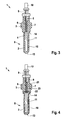
- Fig. 3 shows a heater 1 in a schematic representation according to a third embodiment of the invention.
- the self-regulating heating element 2 is completely enclosed by the housing part 3.
- the maximum temperature of the heating element 2 on the outer surface 11 to a certain
- the heating region 5 of the self-regulating heating element 2 is surrounded by a jacket 15 of the housing part 3, which extends from the tip 13 to the sealing cone 14, wherein thermal damage of the sheath 15 is prevented.
- the housing part 3 with the sheath 15 therefore encloses both the heating area 5a and the contacting area 4 of the heating element 2.
- the material used for the housing part 3 is in particular a temperature-resistant, impact-resistant and highly heat-conducting plastic or a suitable composite. A cost-effective production of the housing part 3 is possible by injection molding in one step from a plastic component.
- an additive for improving the heat conduction can be introduced into the material of the housing part 3, in particular in the sheath 15.
- Fig. 4 shows a heating device 1 in a schematic sectional view according to a fourth embodiment of the invention.
- the housing part 3 is formed from a first plastic component 21 and a second plastic component 22.
- the first plastic component 21 partially surrounds the electrical lines 6, 7, which are led through the housing part 3 to the heating element 2, in a region 23.
- the second plastic component 22 surrounds at least one heating region 5 of the heating element 2, wherein in the illustrated embodiment, the heating element 2 is completely enclosed by the second plastic component 22.
- the second Plastic component 22 is formed of a heat-conducting, fuel-resistant material.
- the second plastic component has a heat-conducting filler, which improves the heat conduction from the self-regulating heating element 2 through the second plastic component 22 to the surrounding medium.
- the housing part 3 of two or more plastic components 21, 22 can be used on the one hand, a low-cost standard material and on the other hand, a good heat conductive special material, so that there is a relatively inexpensive production with an optimized heating performance.
- Fig. 5 shows a characteristic of a self-regulating heating element 2 in a diagram for explaining the invention.
- a resistance R in ohms is plotted on the ordinate against the temperature T in degrees Celsius on the abscissa.
- a logarithmic representation is chosen with regard to the resistor R which is plotted on the ordinate.
- the self-regulating heating element 2 is preferably designed as a PTC thermistor, resulting in the relevant temperature range, a positive temperature coefficient of resistance.
- the heating element 2 may be formed on the basis of a barium titanate.
- a largely voltage-independent adjustment can be made to a switching temperature T S.
- the resistance R increases with increasing temperature T continuously, wherein in the illustrated embodiment, a temperature of 200 ° C. can not be exceeded due to the significantly increasing resistance R.
- the switching temperature T S results in a resistance R S , which determines the output heating power of the heating element 2 together with the selected voltage.
- the switching temperature T S can be selected in the range of 120 ° C to 300 ° C by selecting a suitable self-regulating heating element 2, preferably a heating element 2 with a switching temperature between about 170 ° C and 210 ° C is selected to heat fuels.
- the geometric design of the heating element 2 can be defined by a one-sided contacted, cylindrical, elliptical or cuboid body. But there are also other embodiments possible, for example, stacked as a stack and connected in series, disc-shaped heating elements for the design of the heating element. 2
- the housing part 3 may for example be formed from a polyamide having a temperature resistance of more than 260 ° C.
- a material having an improved conductivity can be used, for example E3603 polyamide 4.6 (PA4.6) with a thermal conductivity of 18 W / mK; E5101 Polyphenylene sulfide (PPS) with a thermal conductivity of 20 W / mK which is temperature resistant up to 260 ° C; or a fluoropolymer such as PTFE or PVDF, which have even higher application limits.
- additional fillers up to the processing limit can also be added.
- finely divided powder of metal such as copper or aluminum or other thermally highly conductive materials, such as graphite, silicon carbide and boron nitride, which improve the thermal conductivity.
- the heat dissipation over the composite surface can be optimized by thin wall thicknesses or by enlarging the surface by means of structuring.
- Fig. 6 shows a heater 1 in a schematic representation according to a fifth embodiment.
- the self-regulating heating element 2 is designed in the heating area 5 as a ring or perforated disc. This allows an advantageous flow around the heating element 2 with fuel, for example in a fuel line.
- Fig. 7 shows a heater 1 in a schematic representation according to a sixth embodiment of the invention.
- the heating element 2 is designed key-shaped, so that also results in an enlarged surface.
- Fig. 8 shows a heater 1 in a schematic representation according to a seventh embodiment.
- the self-regulating heating element 2 is designed disc-shaped, so that an improved heat dissipation to the surrounding medium can be achieved.
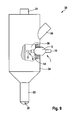
- Fig. 9 shows a configured as a fuel injection valve 30 component of a fuel injection system according to an embodiment of the invention.
- the fuel injection valve 30 has an electrical connection 31, by means of which the fuel injection valve 30 can be connected via electrical lines to a control unit in order to control the spraying of fuel via at least one nozzle opening 32 into a nozzle body 33.
- the fuel injection valve 30 has a valve housing 34 connected to the nozzle body 33, on which a fuel inlet pipe 35 is provided. Fuel can be introduced into the valve housing 34 via the fuel inlet stub 35, the fuel being guided through the valve housing 34 and the nozzle body 33 to the nozzle opening 32. Simplified is in the Fig.
- FIG. 9 a partially opened view of the fuel injection valve 30 is shown, which shows a fuel chamber 36 within the valve housing 34.
- the fuel chamber 36 can also be formed by a fuel channel.
- the heater 1 is partially screwed into the valve housing 34, wherein a seal on the sealing cone 14 of the housing 3 relative to the valve housing 34 takes place.
- the heating element 2 is located in the fuel space 36, so that fuel flowing past the heating area 5 of the heating element 2 is preheated.
- the use of the heater 1 in a fuel injection valve 30, as shown in the Fig. 9 shown is a possible use.
- Other applications also exist in thermotechnology or safety technology, with a compact, overheating-proof heater 1 for cold protection for sensitive outdoor facilities, such as pumps, actuators or cameras, can be used.
Landscapes
- Engineering & Computer Science (AREA)
- Chemical & Material Sciences (AREA)
- Combustion & Propulsion (AREA)
- Mechanical Engineering (AREA)
- General Engineering & Computer Science (AREA)
- Ceramic Engineering (AREA)
- Fuel-Injection Apparatus (AREA)
- Resistance Heating (AREA)
- Feeding And Controlling Fuel (AREA)
Description
- Die Erfindung betrifft eine Heizeinrichtung. Speziell betrifft die Erfindung einen Heizer für flüssige Brennstoffe, der in eine Komponente eines Brennstoffeinspritzsystems integriert sein kann. Dabei eignet sich die Heizeinrichtung unter anderem für ein Brennstoffeinspritzventil von luftverdichtenden, selbstzündenden Brennkraftmaschinen.
- Aus der
DE 40 05 455 A1 ist ein Einspritzventil für eine Brennkraftmaschine bekannt. Dabei ist ein piezoelektrisches Betätigungsglied für eine Ventilnadel vorgesehen. Ferner ist ein mit Brennstoff gefüllter Raum vorgesehen, der über eine Federmembran abgedichtet ist, die zugleich als Rückstellfeder für die Ventilnadel dient. - Bei dem aus der
DE 40 05 455 A1 bekannten Einspritzventil wird der Brennstoff aus dem mit Brennstoff gefüllten Raum bei einer Betätigung der Ventilnadel abgespritzt. Bei dem Einsatz eines solchen bekannten Einspritzventils bei einer Brennstoffeinspritzanlage ergibt sich allerdings das Problem, dass speziell ein Startverhalten eines Motors ungünstig ist. Dieses Problem stellt sich insbesondere, wenn als Brennstoff ein Gemisch aus Benzin und Alkoholen, ein Dieselbrennstoff oder ein Gemisch aus Diesel und organischen Brennstoffen zum Einsatz kommt. - Aus
DE 20 121 116 U1 undEP 1 657 425 A2 sind weitere Heizeinrichtungen bekannt. - Die erfindungsgemäße Heizeinrichtung mit den Merkmalen des Anspruchs 1, das erfindungsgemäße Brennstoffeinspritzventil mit den Merkmalen des Anspruchs 13 und die erfindungsgemäße Komponente eines Brennstoffeinspritzsystems mit den Merkmalen des Anspruchs 14 haben demgegenüber den Vorteil, dass eine vorteilhafte Wärmequelle mit einem sicheren Schutz gegen Überhitzung gewährleistet ist. Speziell kann bei der Aufheizung von flüssigen Brennstoffen ein zuverlässiger Überhitzungsschutz gewährleistet werden, da die Oberflächentemperatur des Heizelements begrenzt werden kann, um die Zündtemperatur eines Brennstoffes, insbesondere eines Brennstoffgemisches, nicht zu überschreiten.
- Durch die in den Unteransprüchen aufgeführten Maßnahmen sind vorteilhafte Weiterbildungen der im Anspruch 1 angegebenen Heizeinrichtung, des im Anspruch 13 angegebenen Brennstoffeinspritzventils und der im Anspruch 14 angegebenen Komponente eines Brennstoffeinspritzsystems möglich.
- Vorteilhaft ist es, dass das selbstregulierende Heizelement einen Kaltleiter aufweist. Ein solcher Kaltleiter ist durch einen PTC-Widerstand gebildet, der im Arbeitsbereich einen positiven Temperaturkoeffizienten aufweist. Mittels eines selbstregulierenden Heizelements ist ein zuverlässiger und schnell ansprechender Überhitzungsschutz gegeben. Beispielsweise ist bei der Vorwärmung von Brennstoffen, wie beispielsweise einem Gemisch aus Ethanol und Benzin, eine Limitierung der Oberflächentemperatur des Heizers auf cirka 200° C von Vorteil, um zu verhindern, dass eine Zündtemperatur des Brennstoffes erreicht wird. Eine solche Situation kann beispielsweise auftreten, wenn die Brennstoffzufuhr unterbrochen ist und der Flüssigkeitspegel im Bereich des Heizelements absinkt, so dass sich ein Gemisch aus Brennstoff und Luft zumindest teilweise im Bereich der Oberfläche des Heizelements bildet.
- In vorteilhafter Weise steht eine Außenfläche des selbstregulierenden Heizelements in direktem Kontakt mit einem flüssigen Brennstoff, wodurch ein guter Wärmeübergang gewährleistet ist. Dabei ist es vorteilhaft, dass das selbstregulierende Heizelement aus einem kraftstoffbeständigen Werkstoff gebildet ist. Dabei kann das selbstregulierende Heizelement auch aus mehreren Werkstoffen bestehen, wobei ein Außenbereich aus einem kraftstoffbeständigen Werkstoff gebildet ist und ein Kernbereich des selbstregulierenden Heizelements aus einem anderen Werkstoff gebildet sein kann.
- Vorteilhaft ist es auch, dass eine Außenfläche des selbstregulierenden Heizelements zumindest teilweise mit einer Schutzschicht beschichtet ist. Die Schutzschicht kann dabei auf einen Teil der Außenfläche begrenzt sein, der anfällig gegenüber der Einwirkung von Brennstoffen ist. Durch die Schutzschicht ist es möglich, eine höhere Widerstandsfähigkeit gegenüber den umgebenden Medien, insbesondere Brennstoff oder Wasser enthaltenden Dieselbrennstoff zu erzielen.
- Ferner ist es vorteilhaft, dass die Schutzschicht Feststoffpigmente aufweist, die eine Wärmeleitfähigkeit der Schutzschicht verbessern. Die Feststoffpigmente können im Wesentlichen aus Bornitrid, Graphit und/oder Saliciumkarbid gebildet sein.
- Das selbstregulierende Heizelement ist von dem Gehäuseteil umschlossen. In diesem Fall ist es ferner von Vorteil, dass das Gehäuseteil aus einem Wärme leitenden Kunststoff oder Komposit gebildet ist. Dabei kann das Gehäuseteil außerdem schlagfest und temperaturbeständig ausgestaltet sein, so dass ein Schutz des Heizelements gegenüber chemischer und mechanischer Beschädigung gewährleistet ist. Dadurch wird auch die Handhabung der Heizeinrichtung erleichtert. Insbesondere werden Beschädigungen beim Transport oder der Montage verhindert.
- Ferner kann das Gehäuseteil auch aus mehreren Kunststoffkomponenten, insbesondere zwei Kunststoffkomponenten, gebildet sein. Hierbei ist es von Vorteil, dass die zweite Kunststoffkomponente, die einen Heizbereich des Heizelements umgibt, aus einem Wärme leitenden, kraftstoffbeständigem Werkstoff gebildet ist, der beispielsweise Wärme leitende Füllstoffe aufweist, um eine gute Wärmeleitung und damit ein relativ schnelles Ansprechverhalten im Hinblick auf einen Überhitzungsschutz zu erzielen. Solch ein Füllstoff kann aus einem Metallpulver, Graphit, Siliciumkarbid und/oder Bornitrid gebildet sein.
- Die Geometrie des Heizelements kann in vorteilhafter Weise an den jeweiligen Anwendungsfall angepasst sein. Speziell kann der Heizbereich stiftförmig, scheibenförmig, lochscheibenförmig, ringförmig oder schlüsselförmig ausgestaltet sein. Dadurch kann zum einen durch die geschaffene Oberfläche die abgegebene Wärmemenge innerhalb gewisser Grenzen vorgegeben werden. Zum anderen kann im Fall der Aufheizung von flüssigen Medien, insbesondere Brennstoff, eine Anpassung an den zur Verfügung stehenden Bauraum und die Strömung des Brennstoffes ermöglicht werden.
- Bevorzugte Ausführungsbeispiele der Erfindung sind in der nachfolgenden Beschreibung anhand der beigefügten Zeichnungen, in denen sich entsprechende Elemente mit übereinstimmenden Bezugszeichen versehen sind, näher erläutert. Es zeigt:
-
Fig. 1 eine Heizeinrichtung in einer schematischen Schnittdarstellung nicht entsprechend einem ersten Ausführungsbeispiel der Erfindung; -
Fig. 2 eine Heizeinrichtung in einer schematischen Schnittdarstellung nicht entsprechend einem zweiten Ausführungsbeispiel der Erfindung; -
Fig. 3 eine Heizeinrichtung in einer schematischen Schnittdarstellung entsprechend einem dritten Ausführungsbeispiel der Erfindung; -
Fig. 4 eine Heizeinrichtung in einer schematischen Schnittdarstellung entsprechend einem vierten Ausführungsbeispiel der Erfindung; -
Fig. 5 eine Kennlinie eines selbstregulierenden Heizelements einer Heizeinrichtung zur Erläuterung der Erfindung; -
Fig. 6 eine Heizeinrichtung in einer schematischen Darstellung entsprechend einem fünften Ausführungsbeispiel der Erfindung; -
Fig. 7 eine Heizeinrichtung in einer schematischen Darstellung entsprechend einem sechsten Ausführungsbeispiel der Erfindung; -
Fig. 8 eine Heizeinrichtung in einer schematischen Darstellung entsprechend einem siebten Ausführungsbeispiel der Erfindung und -
Fig. 9 eine als Brennstoffeinspritzventil ausgestaltete Komponente eines Brennstoffeinspritzsystems mit einer Heizeinrichtung entsprechend einem Ausführungsbeispiel der Erfindung. -
Fig. 1 zeigt eine Heizeinrichtung 1 mit einem selbstregulierenden Heizelement 2 nicht entsprechend einem ersten Ausführungsbeispiel der Erfindung. Die Heizeinrichtung 1 kann insbesondere als Heizer für flüssige Brennstoffe ausgestaltet sein. Speziell eignet sich die Heizeinrichtung für Brennstoffeinspritzanlagen von gemischverdichtenden, fremdgezündeten Brennkraftmaschinen oder von luftverdichtenden, selbstzündenden Brennkraftmaschinen, wobei als Brennstoff Benzin, Diesel, ein Gemisch aus Benzin oder Diesel mit anderen Brennstoffen oder dergleichen zum Einsatz kommen kann. Dabei können als Brennstoff oder Brennstoffkomponenten auch Alkohole, insbesondere Methanol oder Ethanol oder biologische Kraftstoffe, insbesondere Öle wie Rapsöl, zum Einsatz kommen. - Die erfindungsgemäße Heizeinrichtung 1 eignet sich jedoch auch für andere Anwendungsfälle.
- Die Heizeinrichtung 1 weist ein Gehäuseteil 3 auf, in das das selbstregulierende Heizelement 2 teilweise eingebettet ist. Dabei ist ein Kontaktierungsbereich 4 des Heizelements 2 zumindest im Wesentlichen von dem Gehäuseteil 3 umgeben, während ein Heizbereich 5 des Heizelements 2 zumindest im Wesentlichen frei liegt, um einen direkten Kontakt mit einem flüssigen Medium, insbesondere flüssigem Brennstoff, zu ermöglichen. Im Kontaktierungsbereich 4 ist das Heizelement 2 mit zwei elektrischen Leitungen 6, 7 kontaktiert, die durch das Gehäuseteil 3 geführt sind, wodurch diese gegenüber der Umgebung abgedichtet sind. Die elektrische Leitung 7 verbindet das Heizelement 2 mit einem metallischen Kontaktelement 8, das beispielsweise einen Minuskontakt bildet. Die elektrische Leitung 6 ist einerseits mit dem Heizelement 2 verbunden. Ferner ist die elektrische Leitung 6 durch das Kontaktelement 8 und einen Isolationskörper 9 geführt, wobei die elektrische Leitung 6 gegenüber dem Kontaktelement 8 elektrisch isoliert ist. Außerdem ist ein Rundstecker 10 vorgesehen, der gegenüber dem Kontaktelement 8 mittels des Isolationskörper 9 isoliert und mit der elektrischen Leitung 6 verbunden ist. Durch Anlegen einer elektrischen Spannung an den Rundstecker 10 gegenüber dem mit Masse verbundenen Kontaktelement 8 kann das selbstregulierende Heizelement 2 mit einer gewünschten Spannung beaufschlagt werden, um eine Aufheizung des Heizelements 2 zumindest in dem Heizbereich 5 zu erzielen.
- Bei der in
Fig. 1 dargestellten Heizeinrichtung 1 ist eine Außenfläche 11 des selbstregulierenden Heizelements 2 im Heizbereich 5 freiliegend, so dass diese zum direkten Aufheizen eines Brennstoffes dient. Dabei ist das Heizelement im Wesentlichen stift- oder fingerförmig ausgestaltet. Das Heizelement 2 kann so ausgestaltet sein, dass eine Vorstehlänge von 20 mm bis 50 mm des Heizbereichs 5 und ein Durchmesser des Heizelements von 3,5 mm bis 5,5 mm gegeben sind. Es können aber auch andere Dimensionen vorliegen. Speziell bei einem Heizelement 2, bei dem eine mögliche Heiztemperatur auf 200° C oder dergleichen begrenzt ist, können einzelne Komponenten der Heizeinrichtung 1 aus einem Temperatur beständigen Kunststoff oder Kompositmaterial gefertigt werden, ohne dass es zu einer thermisch bedingten Beschädigung dieser Komponenten kommt. Beispielsweise kann das Gehäuseteil 3 aus einem Temperatur beständigen Kunststoff oder Kompositmaterial gebildet sein. Dabei kommen vorzugsweise Kunststoffe zum Einsatz, die gegenüber dem zu erwärmenden Medium, insbesondere Brennstoff, ausreichend resistent sind. - Ferner ist bei der in
Fig. 1 dargestellten Heizeinrichtung 1, bei der das Heizelement 2 im Heizbereich 5 im direkten Kontakt mit dem Brennstoff steht, das Heizelement 2 aus einem Werkstoff gebildet, der gegenüber dem Brennstoff unter Berücksichtigung des möglichen Temperaturbereichs ausreichend resistent ist. Dies betrifft auch die Resistenz gegenüber organischen Säuren und dergleichen, die sich aus dem Brennstoff oder dem Brennstoffgemisch bilden können sowie gegenüber Halogenid haltigen wässrigen Lösungen. Der Werkstoff kann dabei aber in Bezug auf den jeweiligen Anwendungsfall und somit auf das jeweils mit dem Heizelement 2 in Berührung stehendem Medium optimiert sein. - Um eine schnelle und wirkungsvolle Aufheizung des umgebenden Mediums zu gewährleisten, ist in der Regel über eine relativ kleine Fläche eine hohe Wärmeabgabe erforderlich. Eine typische geforderte Heizleistung liegt bei etwa 150 W bis 250 W. Speziell im Fall eines Gehäuseteils 3, das auch den Heizbereich 5 teilweise umschließt, ist ein guter Wärmetransport durch das Gehäuseteil 3 von Vorteil.
- Da das in der
Fig. 1 dargestellte Heizelement im direkten Kontakt mit einem brennbaren Brennstoff steht, ist ein zuverlässiger und schnell ansprechender Überhitzungsschutz erforderlich. Eine Außenfläche 11 des Heizelements 2 sollte die Zündtemperatur des Brennstoffes zu keinem Zeitpunkt überschreiten. Typischerweise ist die Wärmeabgabe des Heizelements 2 in Flüssigkeiten cirka vier- bis sechsfach höher als an Luft. Deshalb kann beim Absinken des Flüssigkeitsniveaus, beispielsweise bei einer Unterbrechung der Brennstoffzufuhr, schon nach sehr kurzer Zeit Überhitzung eintreten. Dadurch besteht die Gefahr der Entflammung oder Explosion des Brennstoff-Luft-Gemisches. Dementsprechend wichtig ist ein schnell ansprechender Überhitzungsschutz, der die Oberflächentemperatur des Heizelements 2 an der Außenfläche 11 limitiert, beispielsweise auf unter 200° C. Dadurch ist verhindert, dass die Zündtemperatur des Brennstoffgemisches erreicht wird. Beispielsweise liegt die Zündtemperatur von Benzin je nach Zusammensetzung im Bereich von etwa 200° C bis 280° C. Die Zündtemperatur von Methanol, Ethanol oder Mischungen liegt im Bereich von cirka 400° C bis 430° C. In Bezug auf den jeweiligen Anwendungsfall kann gegebenenfalls eine Optimierung hinsichtlich des gewählten Heizelements 2 erfolgen, um einerseits eine hohe Wärmeabgabe und andererseits einen zuverlässigen Überhitzungsschutz zu gewährleisten. - Das Gehäuseteil 3 nimmt das Heizelement 2 auf und bildet die äußere Form der Heizeinrichtung 1. Das Gehäuseteil 3 ist aus einem Temperatur beständigen und schlagfesten Kunststoff gebildet und kann beispielsweise im Spritzguss in einem Schritt aus einer Kunststoffkomponente gefertigt sein, so dass eine kostengünstige Herstellung der Heizeinrichtung 1 möglich ist.
-
Fig. 2 zeigt eine Heizeinrichtung 1 in einer schematischen Darstellung nicht entsprechend einem zweiten Ausführungsbeispiel der Erfindung. In diesem Ausführungsbeispiel ist die Außenfläche 11 des Heizelements 2 der Heizeinrichtung 1 zumindest im Heizbereich 5 mit einer Schutzschicht 12 beschichtet. Die Schutzschicht 12 erstreckt sich dabei von einer Spitze 13 des Heizelements 2 bis zu einem Dichtkonus 14, der an dem Gehäuseteil 3 ausgebildet ist. Die Schutzschicht 12 kann nachträglich auf das Heizelement 2 aufgetragen werden, beispielsweise durch Tauchen oder Aufstreichen. In vorteilhafter Weise ist die Schutzschicht 12 aus einem Medien resistenten, insbesondere Brennstoff resistenten, Schutzlack ausgestaltet, der durch Zuschläge von geeigneten Feststoffpigmenten besonders gut wärmeleitfähig ist. Als Feststoffpigmente kommen beispielsweise Bornitrid, Graphit und/oder Saliciumkarbid in Frage. Beispielsweise kann die Schutzschicht 12 aus einem mit Bornitrid gefüllten Epoxitharz oder Silikonkleber gebildet sein. -
Fig. 3 zeigt eine Heizeinrichtung 1 in einer schematischen Darstellung entsprechend einem dritten Ausführungsbeispiel der Erfindung. In diesem Ausführungsbeispiel ist das selbstregulierende Heizelement 2 vollständig von dem Gehäuseteil 3 umschlossen. In Abhängigkeit von der Ausgestaltung des Heizelements 2 ist die maximale Temperatur des Heizelements 2 an der Außenfläche 11 auf einen gewissen - Wert begrenzt, so dass eine thermische Beschädigung des Gehäuseteils 3 durch eine geeignete Wahl eines Werkstoffes durch das Gehäuseteil 3 verhindert werden kann. Speziell ist der Heizbereich 5 des selbstregulierenden Heizelements 2 mit einer Ummantelung 15 des Gehäuseteils 3 umgeben, die sich von der Spitze 13 bis zu dem Dichtkonus 14 erstreckt, wobei eine thermische Beschädigung der Ummantelung 15 verhindert ist. Das Gehäuseteil 3 mit der Ummantelung 15 umschließt daher sowohl den Heizbereich 5 a als auch den Kontaktierungsbereich 4 des Heizelements 2. Als Werkstoff für das Gehäuseteil 3 eignet sich insbesondere ein Temperatur beständiger, schlagfester und gut Wärme leitender Kunststoff oder ein geeignetes Komposit. Eine kostengünstige Herstellung des Gehäuseteils 3 ist im Spritzguss in einem Schritt aus einer Kunststoffkomponente möglich.
- Je nach Anwendungsfall kann in den Werkstoff des Gehäuseteils 3, insbesondere in die Ummantelung 15, ein Zuschlagstoff zur Verbesserung der Wärmeleitung eingebracht werden.
-
Fig. 4 zeigt eine Heizeinrichtung 1 in einer schematischen Schnittdarstellung entsprechend einem vierten Ausführungsbeispiel der Erfindung. In diesem Ausführungsbeispiel ist das Gehäuseteil 3 aus einer ersten Kunststoffkomponente 21 und einer zweiten Kunststoffkomponente 22 gebildet. Dabei umgibt die erste Kunststoffkomponente 21 in einem Bereich 23 abschnittsweise die elektrischen Leitungen 6, 7, die durch das Gehäuseteil 3 zu dem Heizelement 2 geführt sind. Die zweite Kunststoffkomponente 22 umgibt zumindest einen Heizbereich 5 des Heizelements 2, wobei in dem dargestellten Ausführungsbeispiel das Heizelement 2 vollständig von der zweiten Kunststoffkomponente 22 umschlossen ist. Die zweite Kunststoffkomponente 22 ist aus einem Wärme leitenden, Kraftstoff beständigen Werkstoff gebildet. Dabei weist die zweite Kunststoffkomponente einen Wärme leitenden Füllstoff auf, der die Wärmeleitung von dem selbstregulierenden Heizelement 2 durch die zweite Kunststoffkomponente 22 zu dem umgebenden Medium verbessert. - Durch die Ausgestaltung des Gehäuseteils 3 aus zwei oder mehr Kunststoffkomponenten 21, 22 kann zum einen ein preiswertes Standardmaterial und zum anderen ein gut Wärme leitendes Speziellmaterial eingesetzt werden, so dass sich eine relativ kostengünstige Herstellung bei einer optimierten Heizleistung ergibt.
-
Fig. 5 zeigt eine Kennlinie eines selbstregulierenden Heizelements 2 in einem Diagramm zur Erläuterung der Erfindung. Dabei ist ein Widerstand R in Ohm auf der Ordinate gegen die Temperatur T in Grad Celsius auf der Abszisse angetragen. Hierbei ist bezüglich des an der Ordinate angetragenen Widerstandes R eine logarithmische Darstellung erwählt. Das selbstregulierende Heizelement 2 ist vorzugsweise als Kaltleiter ausgestaltet, wobei sich in dem maßgeblichen Temperaturbereich ein positiver Temperaturkoeffizient des Widerstandes ergibt. Beispielsweise kann das Heizelement 2 auf der Basis eines Bariumtitanats gebildet sein. - Als selbstregulierendes Heizelement 2 kann eine weitgehend spannungsunabhängige Einregelung auf eine Schalttemperatur TS erfolgen. Ausgehend von der Temperatur Tmin, bei der sich ein Widerstand Rmin ergibt, steigt der Widerstand R mit zunehmender Temperatur T kontinuierlich an, wobei in dem dargestellten Ausführungsbeispiel eine Temperatur von 200° C auf Grund des erheblich ansteigenden Widerstandes R nicht überschritten werden kann. Bei der Schalttemperatur TS ergibt sich ein Widerstand RS, der zusammen mit der gewählten Spannung die abgegebene Heizleistung des Heizelement 2 bestimmt. Dadurch ist es möglich, in Abhängigkeit vom jeweiligen Anwendungsfall ein geeignetes Heizelement 2 auszuwählen, bei dem zum einen die abgegebene Heizleistung eine gewünschte Erwärmung des umgebenden Mediums erzielt und zum anderen eine Temperaturbegrenzung, beispielsweise auf unter 200° C, gewährleistet ist. Speziell kann die Schalttemperatur TS im Bereich von 120° C bis 300° C durch Auswahl eines geeigneten selbstregulierenden Heizelements 2 gewählt werden, wobei vorzugsweise ein Heizelement 2 mit einer Schalttemperatur zwischen etwa 170° C und 210° C gewählt ist, um Brennstoffe aufzuheizen.
- Die geometrische Ausgestaltung des Heizelements 2 kann durch einen einseitig kontaktierten, zylindrischen, elliptischen oder quaderförmigen Körper definiert sein. Es sind aber auch andere Ausgestaltungen möglich, beispielsweise mehrere als Stapel geschichtete und in Reihe geschaltete, scheibenförmige Heizelemente zur Ausgestaltung des Heizelements 2.
- Das Gehäuseteil 3 kann beispielsweise aus einem Polyamid gebildet sein, das eine Temperaturbeständigkeit von mehr als 260° C aufweist. Insbesondere für die zweite Kunststoffkomponente 22 kann ein Werkstoff mit einer verbesserten Leitfähigkeit eingesetzt werden, beispielsweise E3603 Polyamid 4,6 (PA4,6) mit einer thermischen Leitfähigkeit von 18 W/mK; E5101 Polyphenylensulfid (PPS) mit einer thermischen Leitfähigkeit von 20 W/mK, das bis 260° C temperaturbeständig ist; oder ein Fluorpolymer wie PTFE oder PVDF, die noch höhere Einsatzgrenzen haben.
- Bei der Verarbeitung und Formgebung eines Komposits für den Heizbereich 5, insbesondere die zweite Kunststoffkomponente 22, können auch zusätzliche Füllstoffe bis zur Verarbeitungsgrenze beigefügt werden. In Frage kommen feinteilige Pulver aus Metall, beispielsweise Kupfer oder Aluminium oder andere thermisch gut leitende Materialien, beispielsweise Graphit, Siliciumkarbid und Bornitrid, die die Wärmeleitfähigkeit verbessern. Zusätzlich kann die Wärmeabfuhr über der Kompositoberfläche durch dünne Wandstärken oder durch Vergrößerung der Oberfläche mittels Strukturierung optimiert werden.
-
Fig. 6 zeigt eine Heizeinrichtung 1 in einer schematischen Darstellung entsprechend einem fünften Ausführungsbeispiel. In diesem Ausführungsbeispiel ist das selbstregulierende Heizelement 2 im Heizbereich 5 als Ring- oder Lochscheibe ausgestaltet. Dies ermöglicht ein vorteilhaftes Umfließen des Heizelements 2 mit Brennstoff, beispielsweise in einer Brennstoffleitung. -
Fig. 7 zeigt eine Heizeinrichtung 1 in einer schematischen Darstellung entsprechend einem sechsten Ausführungsbeispiel der Erfindung. In diesem Ausführungsbeispiel ist das Heizelement 2 schlüsselförmig ausgestaltet, so dass sich ebenfalls eine vergrößerte Oberfläche ergibt. -
Fig. 8 zeigt eine Heizeinrichtung 1 in einer schematischen Darstellung entsprechend einem siebten Ausführungsbeispiel. In diesem Ausführungsbeispiel ist das selbstregulierende Heizelement 2 scheibenförmig ausgestaltet, so dass eine verbesserte Wärmeabgabe an das umgebende Medium erzielt werden kann. - Bei den anhand der
Fig. 6 bis 8 dargestellten Ausführungsbeispielen ist es möglich, zusätzlich eine anhand derFig. 2 bis 4 beschriebenen Maßnahmen vorzusehen. -
Fig. 9 zeigt eine als Brennstoffeinspritzventil 30 ausgestaltete Komponente eines Brennstoffeinspritzsystems entsprechend einem Ausführungsbeispiel der Erfindung. Das Brennstoffeinspritzventil 30 weist einen elektrischen Anschluss 31 auf, mittels dem sich das Brennstoffeinspritzventil 30 über elektrische Leitungen an ein Steuergerät anschließen lässt, um ein Abspritzen von Brennstoff über zumindest eine Düsenöffnung 32 in einen Düsenkörper 33 zu steuern. Ferner weist das Brennstoffeinspritzventil 30 ein mit dem Düsenkörper 33 verbundenes Ventilgehäuse 34 auf, an dem ein Brennstoffeinlassstutzen 35 vorgesehen ist. Über den Brennstoffeinlassstutzen 35 ist Brennstoff in das Ventilgehäuse 34 einleitbar, wobei der Brennstoff durch das Ventilgehäuse 34 und den Düsenkörper 33 zu der Düsenöffnung 32 geführt ist. Vereinfacht ist in derFig. 9 eine teilweise geöffnete Darstellung des Brennstoffeinspritzventils 30 gezeigt, die einen Brennstoffraum 36 innerhalb des Ventilgehäuses 34 zeigt. Der Brennstoffraum 36 kann dabei auch durch einen Brennstoffkanal gebildet sein. Die Heizeinrichtung 1 ist teilweise in das Ventilgehäuse 34 eingeschraubt, wobei eine Abdichtung an dem Dichtkonus 14 des Gehäuses 3 gegenüber dem Ventilgehäuse 34 erfolgt. Dadurch befindet sich das Heizelement 2 in dem Brennstoffraum 36, so dass an dem Heizbereich 5 des Heizelements 2 vorbei fließender Brennstoff vorgewärmt wird. - Es ist anzumerken, dass der Einsatz der Heizeinrichtung 1 in ein Brennstoffeinspritzventil 30, wie es in der
Fig. 9 gezeigt ist, ein möglicher Einsatz ist. Weitere Einsatzmöglichkeiten bestehen auch in der Thermotechnik oder Sicherheitstechnik, wobei eine kompakte, überhitzungssichere Heizeinrichtung 1 zum Kälteschutz für empfindliche Einrichtungen im Außenbereich, beispielsweise Pumpen, Stellmotoren oder Kameras, eingesetzt werden kann. - Die Erfindung ist nicht auf die beschriebenen Ausführungsbeispiele beschränkt.
Claims (5)
- Heizeinrichtung (1), insbesondere Heizer für flüssige Brennstoffe, mit zumindest einem Gehäuseteil (3) und einem zumindest teilweise in das Gehäuseteil (3) eingebetteten Heizelement (2), wobei das Heizelement (2) als selbstregulierendes Heizelement (2) ausgestaltet ist, dadurch gekennzeichnet, dass das selbstregulierende Heizelement (2) von dem Gehäuseteil (3) umschlossen ist, welches aus einem Wärme leitenden Kunststoff oder Komposit gebildet ist.
- Heizeinrichtung nach Anspruch 1, dadurch gekennzeichnet, dass das Gehäuseteil (3) aus einer ersten Kunststoffkomponente (21) und zumindest einer zweiten Kunststoffkomponente (22) gebildet ist, dass die erste Kunststoffkomponente zumindest abschnittsweise elektrische Leitungen (6, 7) zur Kontaktierung des Heizelements (2) umgibt, dass die zweite Kunststoffkomponente (22) einen Heizbereich (5) des Heizelements (2) umgibt und dass die zweite Kunststoffkomponente (22) aus einem Wärme leitenden, kraftstoffbeständigen Werkstoff gebildet ist.
- Heizeinrichtung nach Anspruch 2, dadurch gekennzeichnet, dass die zweite Kunststoffkomponente (22) zumindest einen Wärme leitenden Füllstoff aufweist.
- Heizeinrichtung nach Anspruch 3, dadurch gekennzeichnet, dass der Füllstoff zumindest im Wesentlichen aus einem Metallpulver, Graphit, Saliciumkarbid und/oder Bornitrid gebildet ist.
- Heizeinrichtung nach einem der Ansprüche 1 bis 4, dadurch gekennzeichnet, dass das Heizelement (2) zumindest einen Heizbereich (5) aufweist und dass der Heizbereich stiftförmig, scheibenförmig, lochscheibenförmig, ringförmig oder schlüsselförmig ausgestaltet ist.
Applications Claiming Priority (2)
| Application Number | Priority Date | Filing Date | Title |
|---|---|---|---|
| DE102007049973A DE102007049973A1 (de) | 2007-10-18 | 2007-10-18 | Heizeinrichtung für flüssige Brennstoffe und dergleichen |
| PCT/EP2008/062367 WO2009053174A1 (de) | 2007-10-18 | 2008-09-17 | Heizeinrichtung für flüssige brennstoffe und dergleichen |
Publications (2)
| Publication Number | Publication Date |
|---|---|
| EP2203638A1 EP2203638A1 (de) | 2010-07-07 |
| EP2203638B1 true EP2203638B1 (de) | 2014-05-14 |
Family
ID=40229912
Family Applications (1)
| Application Number | Title | Priority Date | Filing Date |
|---|---|---|---|
| EP08804318.7A Revoked EP2203638B1 (de) | 2007-10-18 | 2008-09-17 | Heizeinrichtung für flüssige brennstoffe und dergleichen |
Country Status (6)
| Country | Link |
|---|---|
| US (1) | US8307813B2 (de) |
| EP (1) | EP2203638B1 (de) |
| JP (2) | JP2011501093A (de) |
| BR (1) | BRPI0816107A2 (de) |
| DE (1) | DE102007049973A1 (de) |
| WO (1) | WO2009053174A1 (de) |
Families Citing this family (4)
| Publication number | Priority date | Publication date | Assignee | Title |
|---|---|---|---|---|
| CN201771638U (zh) * | 2010-09-01 | 2011-03-23 | 中国电子科技集团公司第十三研究所 | 一种油电分离型柴油加热器 |
| US9476393B2 (en) | 2013-03-19 | 2016-10-25 | Delphi Technologies, Inc. | Heated fuel injector |
| US9840992B2 (en) * | 2015-03-06 | 2017-12-12 | Elwha Llc | Fuel injector system and method for making air-filled diesel droplets |
| CN108730079B (zh) * | 2018-08-20 | 2023-09-08 | 山东宇升电子科技有限公司 | 车辆油路加热装置 |
Family Cites Families (28)
| Publication number | Priority date | Publication date | Assignee | Title |
|---|---|---|---|---|
| US4485778A (en) * | 1980-02-27 | 1984-12-04 | Oliver Bernard M | Method and means for improving performance of diesel engines |
| GB2100559B (en) | 1981-06-15 | 1985-05-15 | Raychem Corp | Fuel line heater feedthrough |
| JPS59231321A (ja) * | 1983-06-13 | 1984-12-26 | Ngk Spark Plug Co Ltd | 自己制御型グロ−プラグ |
| JPH06100340B2 (ja) * | 1986-09-27 | 1994-12-12 | 日本特殊陶業株式会社 | 自己制御型セラミツクグロ−プラグ |
| DE4005455A1 (de) | 1989-02-28 | 1990-08-30 | Volkswagen Ag | Zumessventil, insbesondere kraftstoff-einspritzventil fuer eine brennkraftmaschine |
| JPH07109303B2 (ja) * | 1989-05-26 | 1995-11-22 | 日本特殊陶業株式会社 | 自己制御型セラミックグロープラグ |
| US5050569A (en) * | 1989-12-22 | 1991-09-24 | Texas Instruments Incorporated | Fuel injection system for an internal combustion engine and fuel heating device therefor |
| US5361990A (en) * | 1991-12-20 | 1994-11-08 | Texas Instruments Incorporated | Fuel injector heater |
| JP3325600B2 (ja) * | 1992-05-01 | 2002-09-17 | 株式会社共和 | 制振性と熱伝導性を有するゴムおよび/またはプラスチック成型物 |
| JPH0650220A (ja) * | 1992-07-28 | 1994-02-22 | Texas Instr Japan Ltd | 加熱装置および内燃機関用加熱システム |
| US5400969A (en) * | 1993-09-20 | 1995-03-28 | Keene; Christopher M. | Liquid vaporizer and diffuser |
| JPH07190361A (ja) * | 1993-12-25 | 1995-07-28 | Isuzu Ceramics Kenkyusho:Kk | 自己制御型グロープラグ |
| JPH07217886A (ja) * | 1994-02-07 | 1995-08-18 | Isuzu Ceramics Kenkyusho:Kk | 自己制御型セラミックグロープラグ |
| JPH07293417A (ja) * | 1994-04-22 | 1995-11-07 | Isuzu Ceramics Kenkyusho:Kk | 自己温度制御形グロープラグ |
| US5758826A (en) * | 1996-03-29 | 1998-06-02 | Siemens Automotive Corporation | Fuel injector with internal heater |
| JP3754529B2 (ja) * | 1997-05-01 | 2006-03-15 | 日本特殊陶業株式会社 | 自己制御型セラミックヒータ |
| ES2230758T3 (es) * | 1999-03-18 | 2005-05-01 | David + Baader Dbk Spezialfabrik Elektrischer Apparate Und Heizwiderstande Gmbh | Dispositivo de calentamiento para gasoleo y sistema de filtrado de gasoleo calentado. |
| JP2001135794A (ja) | 1999-11-04 | 2001-05-18 | Rohm Co Ltd | 半導体装置、および半導体装置におけるトリミング方法 |
| JP2001357964A (ja) * | 2000-06-12 | 2001-12-26 | Shin Etsu Chem Co Ltd | 複層セラミックスヒーター |
| DE20021203U1 (de) * | 2000-12-14 | 2001-05-31 | Hartinger, Werner, 92723 Tännesberg | Einspritzdüsenvorheizung für Pflanzenölbetrieb |
| JP2003049739A (ja) * | 2001-08-07 | 2003-02-21 | Denso Corp | 燃料噴射弁 |
| DE20121116U1 (de) * | 2001-12-21 | 2003-04-24 | Fritz Eichenauer GmbH & Co. KG, 76870 Kandel | Elektrische Heizeinrichtung zum Beheizen einer Flüssigkeit in einem Kfz |
| DE102004054625A1 (de) * | 2004-11-11 | 2006-05-18 | Mann + Hummel Gmbh | Widerstandsheizung |
| DE102005011182A1 (de) | 2005-03-09 | 2006-09-14 | Mann + Hummel Gmbh | Heizeinrichtung für Kraftstoffe |
| ATE487877T1 (de) | 2005-06-06 | 2010-11-15 | Bosch Do Brasil | Kraftstofferwärmungsanordnung und verfahren zum vorwärmen von kraftstoff eines verbrennungsmotors |
| JP2007100641A (ja) * | 2005-10-06 | 2007-04-19 | Hitachi Ltd | 燃料噴射弁 |
| US20070235086A1 (en) * | 2006-03-21 | 2007-10-11 | Siemens Vdo Automotive Corporation | Fuel injector with inductive heater |
| US20080060621A1 (en) * | 2006-09-13 | 2008-03-13 | Trapasso David J | Heated fuel injector for cold starting of ethanol-fueled engines |
-
2007
- 2007-10-18 DE DE102007049973A patent/DE102007049973A1/de not_active Withdrawn
-
2008
- 2008-09-17 BR BRPI0816107-0A2A patent/BRPI0816107A2/pt not_active Application Discontinuation
- 2008-09-17 WO PCT/EP2008/062367 patent/WO2009053174A1/de not_active Ceased
- 2008-09-17 US US12/678,688 patent/US8307813B2/en not_active Expired - Fee Related
- 2008-09-17 JP JP2010529319A patent/JP2011501093A/ja active Pending
- 2008-09-17 EP EP08804318.7A patent/EP2203638B1/de not_active Revoked
-
2012
- 2012-11-20 JP JP2012253904A patent/JP2013079799A/ja active Pending
Also Published As
| Publication number | Publication date |
|---|---|
| JP2011501093A (ja) | 2011-01-06 |
| US20100206268A1 (en) | 2010-08-19 |
| US8307813B2 (en) | 2012-11-13 |
| WO2009053174A1 (de) | 2009-04-30 |
| JP2013079799A (ja) | 2013-05-02 |
| BRPI0816107A2 (pt) | 2015-03-03 |
| DE102007049973A1 (de) | 2009-04-23 |
| EP2203638A1 (de) | 2010-07-07 |
Similar Documents
| Publication | Publication Date | Title |
|---|---|---|
| EP2917555B1 (de) | Vorheizeinrichtung für eine kraftstoffeinspritzanlage | |
| DE69710318T2 (de) | Kraftstoffeinspritzventil mit internem heizer | |
| US20090294552A1 (en) | Heated fuel injector | |
| WO2013068526A1 (de) | Kraftstoffeinspritzanlage und vorheizeinrichtung | |
| WO2009053174A1 (de) | Heizeinrichtung für flüssige brennstoffe und dergleichen | |
| US9476393B2 (en) | Heated fuel injector | |
| US20090008475A1 (en) | Heated fuel injector for cold starting of ethanol-fueled engines | |
| EP2087224A1 (de) | Kraftstoffheizer | |
| DE10325965A1 (de) | Heizeinrichtung für Fluide | |
| JPS60184958A (ja) | コンパクトな抵抗器装置とそれを作る方法 | |
| EP0231298A1 (de) | Heizvorrichtung zum vorwärmen von dieselkraftstoff | |
| DE102012220433A1 (de) | Kraftstoffeinspritzanlage mit Vorheizeinrichtung | |
| EP3282118A1 (de) | Kraftstoffeinspritzanlage mit kraftstoffheizeinrichtung | |
| EP1899646B1 (de) | Glühstiftkerze | |
| DE3429262A1 (de) | Gluehzuender | |
| US9074574B2 (en) | Glow plug and method for producing a glow pencil | |
| DE102017121658A1 (de) | Betätigungseinrichtung mit einem Dehnstoffelement und Ventileinrichtung | |
| DE102008003841A1 (de) | Piezoelektrisches Aktormodul und Brennstoffeinspritzventil | |
| EP1936709A2 (de) | Piezoelektrischer Aktor | |
| DE3125713A1 (de) | Anlasshilfe fuer brennkraftmaschine | |
| DE10240208B4 (de) | Heizgerät mit einem Detektor | |
| DE102015113482A1 (de) | Kraftstoffinjektor mit elektrisch beheizbarer Ventilnadel | |
| WO1999027302A1 (de) | Glühstiftkerze für brennkraftmaschinen | |
| DE102006040246A1 (de) | Glühstiftkerze | |
| WO2005116442A1 (de) | Einspritzventil und verfahren zum herstellen eines einspritzventils |
Legal Events
| Date | Code | Title | Description |
|---|---|---|---|
| PUAI | Public reference made under article 153(3) epc to a published international application that has entered the european phase |
Free format text: ORIGINAL CODE: 0009012 |
|
| 17P | Request for examination filed |
Effective date: 20100518 |
|
| AK | Designated contracting states |
Kind code of ref document: A1 Designated state(s): AT BE BG CH CY CZ DE DK EE ES FI FR GB GR HR HU IE IS IT LI LT LU LV MC MT NL NO PL PT RO SE SI SK TR |
|
| AX | Request for extension of the european patent |
Extension state: AL BA MK RS |
|
| DAX | Request for extension of the european patent (deleted) | ||
| REG | Reference to a national code |
Ref country code: DE Ref legal event code: R079 Ref document number: 502008011771 Country of ref document: DE Free format text: PREVIOUS MAIN CLASS: F02M0031125000 Ipc: F02N0019040000 |
|
| RIC1 | Information provided on ipc code assigned before grant |
Ipc: F02N 19/04 20100101AFI20131121BHEP |
|
| GRAP | Despatch of communication of intention to grant a patent |
Free format text: ORIGINAL CODE: EPIDOSNIGR1 |
|
| INTG | Intention to grant announced |
Effective date: 20140219 |
|
| GRAS | Grant fee paid |
Free format text: ORIGINAL CODE: EPIDOSNIGR3 |
|
| GRAA | (expected) grant |
Free format text: ORIGINAL CODE: 0009210 |
|
| AK | Designated contracting states |
Kind code of ref document: B1 Designated state(s): AT BE BG CH CY CZ DE DK EE ES FI FR GB GR HR HU IE IS IT LI LT LU LV MC MT NL NO PL PT RO SE SI SK TR |
|
| REG | Reference to a national code |
Ref country code: GB Ref legal event code: FG4D Free format text: NOT ENGLISH |
|
| REG | Reference to a national code |
Ref country code: AT Ref legal event code: REF Ref document number: 668476 Country of ref document: AT Kind code of ref document: T Effective date: 20140615 |
|
| REG | Reference to a national code |
Ref country code: IE Ref legal event code: FG4D Free format text: LANGUAGE OF EP DOCUMENT: GERMAN |
|
| REG | Reference to a national code |
Ref country code: DE Ref legal event code: R096 Ref document number: 502008011771 Country of ref document: DE Effective date: 20140626 |
|
| REG | Reference to a national code |
Ref country code: NL Ref legal event code: VDEP Effective date: 20140514 |
|
| REG | Reference to a national code |
Ref country code: LT Ref legal event code: MG4D |
|
| PG25 | Lapsed in a contracting state [announced via postgrant information from national office to epo] |
Ref country code: CY Free format text: LAPSE BECAUSE OF FAILURE TO SUBMIT A TRANSLATION OF THE DESCRIPTION OR TO PAY THE FEE WITHIN THE PRESCRIBED TIME-LIMIT Effective date: 20140514 Ref country code: GR Free format text: LAPSE BECAUSE OF FAILURE TO SUBMIT A TRANSLATION OF THE DESCRIPTION OR TO PAY THE FEE WITHIN THE PRESCRIBED TIME-LIMIT Effective date: 20140815 Ref country code: IS Free format text: LAPSE BECAUSE OF FAILURE TO SUBMIT A TRANSLATION OF THE DESCRIPTION OR TO PAY THE FEE WITHIN THE PRESCRIBED TIME-LIMIT Effective date: 20140914 Ref country code: LT Free format text: LAPSE BECAUSE OF FAILURE TO SUBMIT A TRANSLATION OF THE DESCRIPTION OR TO PAY THE FEE WITHIN THE PRESCRIBED TIME-LIMIT Effective date: 20140514 Ref country code: NO Free format text: LAPSE BECAUSE OF FAILURE TO SUBMIT A TRANSLATION OF THE DESCRIPTION OR TO PAY THE FEE WITHIN THE PRESCRIBED TIME-LIMIT Effective date: 20140814 Ref country code: FI Free format text: LAPSE BECAUSE OF FAILURE TO SUBMIT A TRANSLATION OF THE DESCRIPTION OR TO PAY THE FEE WITHIN THE PRESCRIBED TIME-LIMIT Effective date: 20140514 |
|
| PG25 | Lapsed in a contracting state [announced via postgrant information from national office to epo] |
Ref country code: SE Free format text: LAPSE BECAUSE OF FAILURE TO SUBMIT A TRANSLATION OF THE DESCRIPTION OR TO PAY THE FEE WITHIN THE PRESCRIBED TIME-LIMIT Effective date: 20140514 Ref country code: ES Free format text: LAPSE BECAUSE OF FAILURE TO SUBMIT A TRANSLATION OF THE DESCRIPTION OR TO PAY THE FEE WITHIN THE PRESCRIBED TIME-LIMIT Effective date: 20140514 Ref country code: LV Free format text: LAPSE BECAUSE OF FAILURE TO SUBMIT A TRANSLATION OF THE DESCRIPTION OR TO PAY THE FEE WITHIN THE PRESCRIBED TIME-LIMIT Effective date: 20140514 Ref country code: PL Free format text: LAPSE BECAUSE OF FAILURE TO SUBMIT A TRANSLATION OF THE DESCRIPTION OR TO PAY THE FEE WITHIN THE PRESCRIBED TIME-LIMIT Effective date: 20140514 Ref country code: HR Free format text: LAPSE BECAUSE OF FAILURE TO SUBMIT A TRANSLATION OF THE DESCRIPTION OR TO PAY THE FEE WITHIN THE PRESCRIBED TIME-LIMIT Effective date: 20140514 |
|
| PG25 | Lapsed in a contracting state [announced via postgrant information from national office to epo] |
Ref country code: PT Free format text: LAPSE BECAUSE OF FAILURE TO SUBMIT A TRANSLATION OF THE DESCRIPTION OR TO PAY THE FEE WITHIN THE PRESCRIBED TIME-LIMIT Effective date: 20140915 |
|
| PG25 | Lapsed in a contracting state [announced via postgrant information from national office to epo] |
Ref country code: RO Free format text: LAPSE BECAUSE OF FAILURE TO SUBMIT A TRANSLATION OF THE DESCRIPTION OR TO PAY THE FEE WITHIN THE PRESCRIBED TIME-LIMIT Effective date: 20140514 Ref country code: DK Free format text: LAPSE BECAUSE OF FAILURE TO SUBMIT A TRANSLATION OF THE DESCRIPTION OR TO PAY THE FEE WITHIN THE PRESCRIBED TIME-LIMIT Effective date: 20140514 Ref country code: CZ Free format text: LAPSE BECAUSE OF FAILURE TO SUBMIT A TRANSLATION OF THE DESCRIPTION OR TO PAY THE FEE WITHIN THE PRESCRIBED TIME-LIMIT Effective date: 20140514 Ref country code: SK Free format text: LAPSE BECAUSE OF FAILURE TO SUBMIT A TRANSLATION OF THE DESCRIPTION OR TO PAY THE FEE WITHIN THE PRESCRIBED TIME-LIMIT Effective date: 20140514 Ref country code: EE Free format text: LAPSE BECAUSE OF FAILURE TO SUBMIT A TRANSLATION OF THE DESCRIPTION OR TO PAY THE FEE WITHIN THE PRESCRIBED TIME-LIMIT Effective date: 20140514 |
|
| REG | Reference to a national code |
Ref country code: DE Ref legal event code: R026 Ref document number: 502008011771 Country of ref document: DE |
|
| PLBI | Opposition filed |
Free format text: ORIGINAL CODE: 0009260 |
|
| PG25 | Lapsed in a contracting state [announced via postgrant information from national office to epo] |
Ref country code: NL Free format text: LAPSE BECAUSE OF FAILURE TO SUBMIT A TRANSLATION OF THE DESCRIPTION OR TO PAY THE FEE WITHIN THE PRESCRIBED TIME-LIMIT Effective date: 20140514 |
|
| PLAX | Notice of opposition and request to file observation + time limit sent |
Free format text: ORIGINAL CODE: EPIDOSNOBS2 |
|
| 26 | Opposition filed |
Opponent name: DBK DAVID + BAADER GMBH Effective date: 20150212 |
|
| PG25 | Lapsed in a contracting state [announced via postgrant information from national office to epo] |
Ref country code: MC Free format text: LAPSE BECAUSE OF FAILURE TO SUBMIT A TRANSLATION OF THE DESCRIPTION OR TO PAY THE FEE WITHIN THE PRESCRIBED TIME-LIMIT Effective date: 20140514 Ref country code: LU Free format text: LAPSE BECAUSE OF FAILURE TO SUBMIT A TRANSLATION OF THE DESCRIPTION OR TO PAY THE FEE WITHIN THE PRESCRIBED TIME-LIMIT Effective date: 20140917 Ref country code: IT Free format text: LAPSE BECAUSE OF FAILURE TO SUBMIT A TRANSLATION OF THE DESCRIPTION OR TO PAY THE FEE WITHIN THE PRESCRIBED TIME-LIMIT Effective date: 20140514 |
|
| REG | Reference to a national code |
Ref country code: DE Ref legal event code: R026 Ref document number: 502008011771 Country of ref document: DE Effective date: 20150212 Ref country code: CH Ref legal event code: PL |
|
| GBPC | Gb: european patent ceased through non-payment of renewal fee |
Effective date: 20140917 |
|
| REG | Reference to a national code |
Ref country code: IE Ref legal event code: MM4A |
|
| PG25 | Lapsed in a contracting state [announced via postgrant information from national office to epo] |
Ref country code: BE Free format text: LAPSE BECAUSE OF NON-PAYMENT OF DUE FEES Effective date: 20140930 |
|
| PG25 | Lapsed in a contracting state [announced via postgrant information from national office to epo] |
Ref country code: GB Free format text: LAPSE BECAUSE OF NON-PAYMENT OF DUE FEES Effective date: 20140917 Ref country code: SI Free format text: LAPSE BECAUSE OF FAILURE TO SUBMIT A TRANSLATION OF THE DESCRIPTION OR TO PAY THE FEE WITHIN THE PRESCRIBED TIME-LIMIT Effective date: 20140514 Ref country code: CH Free format text: LAPSE BECAUSE OF NON-PAYMENT OF DUE FEES Effective date: 20140930 Ref country code: LI Free format text: LAPSE BECAUSE OF NON-PAYMENT OF DUE FEES Effective date: 20140930 |
|
| PLBB | Reply of patent proprietor to notice(s) of opposition received |
Free format text: ORIGINAL CODE: EPIDOSNOBS3 |
|
| PG25 | Lapsed in a contracting state [announced via postgrant information from national office to epo] |
Ref country code: IE Free format text: LAPSE BECAUSE OF NON-PAYMENT OF DUE FEES Effective date: 20140917 |
|
| REG | Reference to a national code |
Ref country code: AT Ref legal event code: MM01 Ref document number: 668476 Country of ref document: AT Kind code of ref document: T Effective date: 20140917 |
|
| PG25 | Lapsed in a contracting state [announced via postgrant information from national office to epo] |
Ref country code: AT Free format text: LAPSE BECAUSE OF NON-PAYMENT OF DUE FEES Effective date: 20140917 |
|
| PG25 | Lapsed in a contracting state [announced via postgrant information from national office to epo] |
Ref country code: BG Free format text: LAPSE BECAUSE OF FAILURE TO SUBMIT A TRANSLATION OF THE DESCRIPTION OR TO PAY THE FEE WITHIN THE PRESCRIBED TIME-LIMIT Effective date: 20140514 |
|
| PG25 | Lapsed in a contracting state [announced via postgrant information from national office to epo] |
Ref country code: MT Free format text: LAPSE BECAUSE OF FAILURE TO SUBMIT A TRANSLATION OF THE DESCRIPTION OR TO PAY THE FEE WITHIN THE PRESCRIBED TIME-LIMIT Effective date: 20140514 |
|
| PG25 | Lapsed in a contracting state [announced via postgrant information from national office to epo] |
Ref country code: HU Free format text: LAPSE BECAUSE OF FAILURE TO SUBMIT A TRANSLATION OF THE DESCRIPTION OR TO PAY THE FEE WITHIN THE PRESCRIBED TIME-LIMIT; INVALID AB INITIO Effective date: 20080917 Ref country code: TR Free format text: LAPSE BECAUSE OF FAILURE TO SUBMIT A TRANSLATION OF THE DESCRIPTION OR TO PAY THE FEE WITHIN THE PRESCRIBED TIME-LIMIT Effective date: 20140514 |
|
| REG | Reference to a national code |
Ref country code: FR Ref legal event code: PLFP Year of fee payment: 9 |
|
| PGFP | Annual fee paid to national office [announced via postgrant information from national office to epo] |
Ref country code: FR Payment date: 20160922 Year of fee payment: 9 |
|
| PGFP | Annual fee paid to national office [announced via postgrant information from national office to epo] |
Ref country code: DE Payment date: 20161125 Year of fee payment: 9 |
|
| REG | Reference to a national code |
Ref country code: DE Ref legal event code: R064 Ref document number: 502008011771 Country of ref document: DE Ref country code: DE Ref legal event code: R103 Ref document number: 502008011771 Country of ref document: DE |
|
| PLAB | Opposition data, opponent's data or that of the opponent's representative modified |
Free format text: ORIGINAL CODE: 0009299OPPO |
|
| R26 | Opposition filed (corrected) |
Opponent name: DBK DAVID + BAADER GMBH Effective date: 20150212 |
|
| PLAB | Opposition data, opponent's data or that of the opponent's representative modified |
Free format text: ORIGINAL CODE: 0009299OPPO |
|
| RDAF | Communication despatched that patent is revoked |
Free format text: ORIGINAL CODE: EPIDOSNREV1 |
|
| STAA | Information on the status of an ep patent application or granted ep patent |
Free format text: STATUS: THE PATENT HAS BEEN GRANTED |
|
| RDAD | Information modified related to despatch of communication that patent is revoked |
Free format text: ORIGINAL CODE: EPIDOSCREV1 |
|
| R26 | Opposition filed (corrected) |
Opponent name: DBK DAVID + BAADER GMBH Effective date: 20150212 |
|
| RDAG | Patent revoked |
Free format text: ORIGINAL CODE: 0009271 |
|
| 27W | Patent revoked |
Effective date: 20170323 |
|
| REG | Reference to a national code |
Ref country code: AT Ref legal event code: MA03 Ref document number: 668476 Country of ref document: AT Kind code of ref document: T Effective date: 20170323 |
|
| STAA | Information on the status of an ep patent application or granted ep patent |
Free format text: STATUS: PATENT REVOKED |