EP2202997B1 - Anti-feedback device and anti-feedback method - Google Patents
Anti-feedback device and anti-feedback method Download PDFInfo
- Publication number
- EP2202997B1 EP2202997B1 EP09180288A EP09180288A EP2202997B1 EP 2202997 B1 EP2202997 B1 EP 2202997B1 EP 09180288 A EP09180288 A EP 09180288A EP 09180288 A EP09180288 A EP 09180288A EP 2202997 B1 EP2202997 B1 EP 2202997B1
- Authority
- EP
- European Patent Office
- Prior art keywords
- signal
- filter
- band
- feedback
- output
- Prior art date
- Legal status (The legal status is an assumption and is not a legal conclusion. Google has not performed a legal analysis and makes no representation as to the accuracy of the status listed.)
- Not-in-force
Links
- 238000000034 method Methods 0.000 title claims description 15
- 230000003044 adaptive effect Effects 0.000 claims abstract description 121
- 238000001914 filtration Methods 0.000 claims abstract description 99
- 230000001629 suppression Effects 0.000 claims abstract description 11
- 238000005070 sampling Methods 0.000 claims description 61
- 238000006243 chemical reaction Methods 0.000 claims description 27
- 238000001514 detection method Methods 0.000 claims description 11
- 230000003247 decreasing effect Effects 0.000 claims 1
- 230000002238 attenuated effect Effects 0.000 description 9
- 238000001228 spectrum Methods 0.000 description 8
- 230000003321 amplification Effects 0.000 description 6
- 230000005540 biological transmission Effects 0.000 description 6
- 238000003199 nucleic acid amplification method Methods 0.000 description 6
- 239000000284 extract Substances 0.000 description 4
- 238000000605 extraction Methods 0.000 description 4
- 230000001747 exhibiting effect Effects 0.000 description 3
- 238000004364 calculation method Methods 0.000 description 2
- 230000002708 enhancing effect Effects 0.000 description 2
- 238000004458 analytical method Methods 0.000 description 1
- 239000000470 constituent Substances 0.000 description 1
- 230000001934 delay Effects 0.000 description 1
- 230000014509 gene expression Effects 0.000 description 1
- 230000008054 signal transmission Effects 0.000 description 1
- 230000005236 sound signal Effects 0.000 description 1
Images

Classifications
-
- H—ELECTRICITY
- H04—ELECTRIC COMMUNICATION TECHNIQUE
- H04R—LOUDSPEAKERS, MICROPHONES, GRAMOPHONE PICK-UPS OR LIKE ACOUSTIC ELECTROMECHANICAL TRANSDUCERS; DEAF-AID SETS; PUBLIC ADDRESS SYSTEMS
- H04R3/00—Circuits for transducers, loudspeakers or microphones
- H04R3/02—Circuits for transducers, loudspeakers or microphones for preventing acoustic reaction, i.e. acoustic oscillatory feedback
-
- H—ELECTRICITY
- H04—ELECTRIC COMMUNICATION TECHNIQUE
- H04R—LOUDSPEAKERS, MICROPHONES, GRAMOPHONE PICK-UPS OR LIKE ACOUSTIC ELECTROMECHANICAL TRANSDUCERS; DEAF-AID SETS; PUBLIC ADDRESS SYSTEMS
- H04R2430/00—Signal processing covered by H04R, not provided for in its groups
- H04R2430/03—Synergistic effects of band splitting and sub-band processing
Definitions
- the present invention relates to an art for suppressing feedback by use of an adaptive filter.
- Occurrence of feedback causes problems in many cases in the field of an acoustic feedback system that amplifies a signal of sound collected within single acoustic space by means of a microphone and that emits the thus-amplified signal from a speaker.
- An anti-feedback device utilizing an adaptive filter is available as means for suppressing such feedback.
- Such an anti-feedback device generates from a signal input to the speaker a simulated signal that simulates a circulatory sound component, which originates from a speaker and enters a microphone, by means of an adaptive filter. The simulated signal is cancelled out by the signal output from the microphone.
- the adaptive filter consumes much time before outputting a simulated signal that accurately simulates circulatory sound achieved after occurrence of a change in the state of the transmission system. For this reason, the anti-feedback device utilizing an adaptive filter encounters a problem of being unable to sufficiently suppress feedback in a situation where an abrupt change arises in the state of the circulatory sound transmission system.
- the anti-feedback device utilizing an adaptive filter also encounters a problem of so-called coloration arising when the adaptive filter has insufficient accuracy in estimation of circulatory sound or when a change arises in positional relationship between a speaker and a microphone.
- Patent Document 1 and Non-Patent Document 1 disclose arts using an adaptive filter and a notch filter in combination as an art for enhancing suppression of feedback.
- An anti-feedback device described in Patent Document 1 suppresses circulatory sound components by means of an adaptive filter.
- a notch filter performs processing for attenuating a component of frequency at which feedback arises by means of a signal acquired by way of a microphone.
- An anti-feedback device described in Non-Patent Document 1 suppresses a circulatory component by means of an adaptive filter of PEM-AFROW type.
- a notch filter performs processing for estimating a frequency at which a transmission system that connects a speaker to a microphone exhibits a peak and for attenuating the thus-estimated frequency component by means of a signal acquired by way of the microphone.
- Non-Patent Document 1 In the art described in Non-Patent Document 1, appropriate suppression of feedback requires an adaptive filter whose filtering coefficient accurately reflects an amplitude characteristic of a closed loop. To this end, updating a filtering coefficient requires a large amount of arithmetic calculation, which raises a problem of difficulty in enhancing the speed of anti-feedback processing.
- Patent Document 2 discloses a low-delay signal processing system for use in a feedforward/feedback headphone system designed to reduce "whistling" when it occurs.
- the signal output by a AD converter is fed, in a feedforward path, to an oversampling processor, and the signal output by the latter is added to the signal that has been downsampled in a decimation filter, processed in a DSP and upsampled in an interpolation filter.
- the oversampling-processor used in the described system includes a low-delay filter and a programmable delay element.
- the present invention has been conceived against such a background and aims at providing an anti-feedback device and an anti-feedback method that can suppress feedback and that can increase the speed of anti-feedback processing.
- an anti-feedback device including: an anti-feedback filter provided in a closed loop including a microphone and a speaker that are disposed in a single acoustic space, wherein an adaptive target signal transfer system includes at least a route from the speaker to the microphone and the anti-feedback filter, a first input processing section that selects a signal belonging to a specific band from a signal output from the adaptive target signal transfer system, and that down-samples the selected signal to a sampling frequency suitable for the specific band and outputs the down-sampled signal; a second input processing section that selects a signal belonging to the specific band from a signal input to the adaptive target signal transfer system, and that down-samples the selected signal to a sampling frequency suitable for the specific band and outputs the down-sampled signal; an adaptive filter that subjects a signal output from the second input processing section to filtering processing, to thus generate a simulated output signal that simulates
- the anti-feedback device down-samples a signal of specific band selected from an output signal of an adaptive target signal transfer system and a signal of the same band selected from an input signal of the adaptive target signal transfer system, and a filtering coefficient of the adaptive filter is updated by use of the down-sampled signals.
- the filter controller controls a filtering characteristic of an anti-feedback filter so that a peak gain of a frequency of an amplitude characteristic within a specific band of a closed loop determined from the filtering coefficient of the adaptive filter is suppressed.
- the filter controller estimates a gain of the closed loop outside the specific band from the amplitude characteristic in the specific band and controls the amount of suppression of the anti-feedback filter outside the band in accordance with a result of estimation. Therefore, the amount of arithmetic computation pertaining to updating of a filtering coefficient of a filter in the adaptive filter is reduced, so that the speed of processing for suppressing feedback over the entire band can be increased.
- an anti-feedback method as in claim 6, i.e. an anti-feedback method in a closed loop including an anti-feedback filter, a microphone and a speaker that are disposed in a single acoustic space, wherein an adaptive target signal transfer system includes at least a route from the speaker to the microphone and the anti-feedback filter, the anti-feedback method including the steps of: selecting a first signal belonging to a specific band from a signal output from the adaptive target signal transfer system; and down-sampling the selected signal to a sampling frequency suitable for the specific band to output the first down-sampled signal; selecting a second signal belonging to the specific band from a signal input to the adaptive target signal transfer system, and down-sampling the selected signal to a sampling frequency suitable for the specific band to output the second down-sampled signal; subjecting the down-sampled signal of the second signal to filtering processing, to thus generate a simulated output signal that simulates the first down-sampled signal output from the adaptive
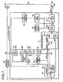
- Fig. 1 shows the configuration of an amplification system including an anti-feedback device 10 of a first embodiment of the present invention.
- the anti-feedback device 10 is a device that performs the function of suppressing feedback in a closed loop including a speaker 91, a microphone 92, the anti-feedback device 10, and an amplifying section 93 (hereinafter called simply a "closed loop").
- the anti-feedback device 10 is interposed between the microphone 92 and the amplifying section 93 of the amplification system that amplifies sound, which has been collected in acoustic space by the microphone 92, through use of the amplifying section 93 and that emits the thus-amplified sound to the acoustic space from the speaker 91.
- a circulatory sound component x (k) and a time ⁇ required by transmission of the circulator sound are determined on the basis of a positional relationship between the speaker 91 and the microphone 92 in the acoustic space.
- the sound collected by the microphone 92 is input as a signal y(k) to the anti-feedback device 10.
- the signal y(k) includes a sound component s(k) developed in the acoustic space and the circulatory sound component x(k) emitted from the speaker 91 a time ⁇ earlier.
- the audio signal y(k) input to the anti-feedback device 10 is amplified by the amplifying section 93 after having undergone signal processing of the anti-feedback device 10.
- a signal u(k) amplified by the amplifying section 93 is input to the speaker 91. Details of signal processing of the anti-feedback device 10 will be described later.
- the speaker 91 emits the signal u(k) input to itself as sound in the acoustic space.
- the microphone 92 receives the signal u(k) input to itself as sound in the acoustic space.
- sound circulation in which some of the sound emitted from the speaker 91 arrives at the microphone 92 as circulatory sound and in which sound including both the circulator sound component x(k) and a sound component s(k) occurred in the acoustic space is collected by the microphone 92.
- An anti-feedback filter 31 is; for instance, an IIR (Infinite Impulse Response) filter.
- the anti-feedback filter 31 subjects the signal y(k) to filtering processing for suppressing feedback, thereby outputting a filtered signal z(k).
- a feedback detection section 33 detects occurrence of feedback in a closed loop in accordance with the signal z(k) output from the anti-feedback filter 31 and a frequency at which feedback arises.
- a method using a bandpass filter has also been known as a method for detecting occurrence of feedback by means of the feedback detection section 33.
- the feedback detection section 33 of the embodiment may also detect feedback by use of any of the methods.
- the notch filter 32 is; for instance, an IIR filter.
- the notch filter 32 subjects the signal z(k) output from the anti-feedback filter 31 to attenuation processing for attenuating a component of the frequency. After starting attenuation processing, the notch filter 32 returns the gain of attenuation processing to a gain achieved before the reduction of the frequency component under control of the filter controller 34, and its detailed descriptions will be provided later.
- a first input processing section 11 selects a signal, which belongs to a low band, from the signal z(k) output to the first input processing section 11 from a signal transfer system (hereinafter called an "adaptive target signal transmission system pw-1") consisting of the speaker 91, a path along which circulatory sound transmits in the acoustic space, the microphone 92, the anti-feedback filter 31, and the notch filter 32.
- the first input processing section down-samples the selected signal to a sampling frequency suitable for the band, outputting the thus-sampled signal.
- a band division section 115 in the first input processing section 11 divides the signal z(k) input from the anti-feedback filter 31 by way of the notch filter 32 into two bands; namely, a high band and a low band, and outputs a high band signal z 1 (k) and a low band signal z 0 (k).
- a second input processing section 12 selects a signal, which belongs to a low band, from a signal u(k) input from the amplifying section 93 to the adaptive target signal transfer system pw-1 and that down-samples the selected signal to a sampling frequency suitable for the band, outputting the thus-sampled signal.
- an LPF 125 in the second input processing section 12 allows passage of only a signal belonging to a band having a frequency of 4 kHz or less in the signal u(k) output from the amplifying section 93.
- a delay section 23 delays the signal u(k') output from the down-sampler 126 by a time ⁇ , outputting the thus-delayed signal.
- a filter 24 performs convolution of a sample train of the signal u(k') supplied by way of the delay section 23 and a filter coefficient set supplied from a filter coefficient update section 25 and outputs a result of convolution processing as a simulated output signal x'(k').
- a subtraction section 26 cancels out the simulated output signal x'(k') by means of the low band signal z 0 (k') output from the down-sampler 116 and outputs a result of cancellation as an error signal e 0 (k').
- the filter coefficient update section 25 updates, in accordance with the error signal e 0 (k'), a filter coefficient set to be supplied to the filter 24.
- a transfer function Ho'(j ⁇ ) of the filter 24 becomes analogous to a transfer function H(j ⁇ ) of the adaptive target signal transfer system pw-1.
- An output processing section 13 up-samples the error signal e 0 (k') output from the adaptive filter 22 to the same sampling frequency as that of the signal z(k) output from the adaptive target signal transfer system pw-1 and adds the up-sampled signal to the high band signal z 1 (k) and outputs a resultant signal to the closed loop.
- An addition section 136 in the output processing section 13 adds the signal e 0 (k) output from the up-sampler 135 to the high band signal z 1 (k) output from the band division section 115 and outputs a result of addition as a signal e(k).
- a time-frequency conversion section 27 determines an amplitude characteristic R( ⁇ ) of the closed loop by means of a filtering coefficient used in filtering processing of the adaptive filter 22. Every time the filter coefficient updating section 25 updates a filtering coefficient of the filter 24, the time-frequency conversion section 27 subjects an updated filter coefficient to FFT, thereby acquiring its transfer function Ho'(j ⁇ ).
- a power spectrum Lo'( ⁇ ) (dB) determined by substituting the transfer function Ho'(j ⁇ ) into the following equation is taken as an amplitude characteristic R( ⁇ ) of the closed loop.
- Lo ⁇ ⁇ 10 ⁇ log 10 Ho ⁇ j ⁇ 2
- the adaptive target signal transfer system pw-1 corresponds to a system obtained by subtracting the first input processing section 11, the adaptive filter 22, the output processing section 13, and the amplifying section 93 from the closed loop.
- the filtering coefficient update section 25 updates a filtering coefficient of the filter 24 in accordance not with the signal z(k) output from the adaptive target signal transfer system pw-1 but with a low band signal z 0 (k') including only a low-band frequency component of the output signal.
- the amplitude characteristic R( ⁇ ) determined from an updated filtering coefficient of the filter 24 by the time-frequency conversion section 27 becomes an amplitude characteristic exhibiting a peak in only a low band and not exhibiting a high-band peak that should originally be present in the amplitude characteristic.
- the filter controller 34 performs first control operation, second control operation, and third control operation.
- the first control operation is a control for controlling a filtering characteristic of the anti-feedback filter 31 so that a low-band gain in the amplitude characteristic R( ⁇ ) determined by the time-frequency conversion section 27 suppresses a gain of the frequency exhibiting a peak;
- the second control operation is a control for estimating a high-band gain in a closed loop in accordance with the amplitude characteristic R( ⁇ ) and controlling the amount of suppression of a high band in the anti-feedback filter 31 in accordance with a result of estimation;
- the third control operation is a control for, when the anti-feedback filter 31 attenuates a signal having the same frequency as that whose gain is reduced through attenuation processing of the notch filter 32, returning a gain of the frequency in the notch filter 32 to a gain acquired before reduction of the signal.
- a frequency ⁇ max 0 -1, a level Lev 0 -1, and a half bandwidth hwid 0 -1 of the maximum peak Po-1 of the amplitude characteristic R( ⁇ ) are first extracted as peak information REF 0-1 .
- the level of the maximum peak Po-1 is sufficiently attenuated, and a frequency ⁇ max 0 -2, a level Lev 0 -2, and a half bandwidth hwid 0 -2 of the attenuated amplitude characteristic R( ⁇ ) are extracted as peak information REF 0 -2.
- like procedures are iterated until a peak exceeding a threshold value TH disappears.
- the filter controller 34 extracts, as peak information REF 1 , an estimated level value (hereinafter described as "estimated level Lev CXT ”) of a high-band peak P 1 that would have appeared in the amplitude characteristic R( ⁇ ) when the filtering coefficient of the filter 24 is updated in accordance with an output signal z(k).
- estimate level Lev CXT an estimated level value of a high-band peak P 1 that would have appeared in the amplitude characteristic R( ⁇ ) when the filtering coefficient of the filter 24 is updated in accordance with an output signal z(k).
- a control signal for commanding that a gain of attenuation processing of the notch filter 32 be retuned to a gain acquired before attenuation is output to the notch filter 32.
- the anti-feedback device 10 of the embodiment selects the low-band signal z 0 (k) among signals y(k) input by way of the microphone 92, and a low-band signal z 0 (k') acquired as a result of down-sampling of the low-band signal z 0 (k) is taken as an object of processing performed by the adaptive filter 22. Meanwhile, an amplitude characteristic of the adaptive target signal transfer system pw-1 determined from the filtering coefficient of the filter 24 in the adaptive filter 22 is taken as an amplitude characteristic R( ⁇ ) of the closed loop.
- the filtering characteristic of the anti-feedback filter 31 is controlled so as to suppress a gain of a frequency at which a low-band gain of the amplitude characteristic R( ⁇ ) exhibits a peak.
- a high-band gain of the closed loop is estimated from the amplitude characteristic R( ⁇ ).
- An amount of suppression of the high band performed by the anti-feedback filter 31 is controlled in accordance with a result of estimation. Therefore, the amount of arithmetic calculation required to update the filtering coefficient of the filter 24 in the adaptive filter 22 is reduced, and processing for suppressing feedback over all frequency bands including the low band and the high band can be performed at high speed.
- an anti-feedback device including: a plurality of anti-feedback filters; a first input processing section that divides the signal output from the adaptive target signal transfer system into a plurality of bands, and that outputs band signals belonging to the divided bands as signals of sampling frequencies suitable for the respective bands; a second input processing section that selects respective band signals belonging to the plurality of bands from a signal input to the adaptive target signal transfer system and that outputs selected band signals as signals of sampling frequencies suitable for the respective bands; a plurality of adaptive filters that correspond to the plurality of respective bands, wherein each adaptive filter subjects the corresponding band signal output from the second input processing section to filtering processing, to thus generate a band-specific simulated output signal simulating the corresponding band signal from the adaptive target signal transfer system by way of the first input processing section, outputs a band-specific error signal generated by canceling the band-specific simulated output signals from the corresponding band signal output by way of the first input processing section, and updates a filtering coefficient for filtering processing so that the
- the anti-feedback device divides a signal input to the adaptive target signal transfer system into signals of a plurality of bands, as well as dividing a signal output from the adaptive target signal transfer system into signals of a plurality of bands.
- the anti-feedback device updates filtering coefficients of the adaptive filters corresponding respectively to the plurality of bands by use of the signals.
- the filter controller controls respective filtering characteristics of a plurality of anti-feedback filters so that a peak gain of frequency of amplitude characteristics of respective bands of a closed loop determined from the respective filtering coefficients of the plurality of adaptive filters is suppressed. Therefore, updating of the filtering coefficients of the adaptive filters and control of filtering characteristics of the anti-feedback filters can simultaneously be performed on a per-band basis. Processing for suppressing feedback over the entire band can be performed at high speed.
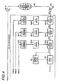
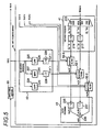
- Figs. 4 and 5 show the configuration of an amplification system including an anti-feedback device 10A of a second embodiment of the present invention.
- constituent elements which are the same as those of the anti-feedback device 10 of the first embodiment ( Fig. 1 ) are assigned the same reference numerals, and their repeated explanations are omitted here for brevity.
- An anti-feedback filter 61-0 of the anti-feedback device 10A subjects a signal y(k) output from the microphone 92 to filtering processing and outputs a filtered signal z(k).
- An anti-feedback filter 61-1 subjects the signal z(k) output from the anti-feedback filter 61-0 to filtering processing and outputs a filtered signal z'(k).
- An anti-feedback filter 61-2 subjects a signal z'(k) output from the anti-feedback filter 61-2 to filtering processing, outputting a filtered signal z"(k).
- the first input processing section 41 divides, into three bands; namely, a low band, an intermediate band, and a high band, the signal z"(k) output to the first input processing section 41 from a signal transfer system (an "adaptive target signal transfer system pw-2") consisting of the speaker 91, a circulatory sound transmission path in an acoustic space, the microphone 92, the anti-feedback filter 61-0, the anti-feedback filter 61-1, the anti-feedback filter 61-2, and the notch filter 32; and outputs band signals belonging to the thus-divided bands as signals having sampling frequencies suitable for the respective bands.
- a signal transfer system an "adaptive target signal transfer system pw-2"
- a band division section 215 in the first input processing section 41 divides the signal z"(k) input from the anti-feedback filter 61-2 by way of the notch filter 32 into three bands; namely, a low band, an intermediate band, and a high band, and outputs three types of band signals, a low-band signal z 0 "(k), an intermediate-band signal z 1 "(k), and a high-band signal z 2 "(k).
- a second input processing section 42 selects band signals belonging to a low band, an intermediate band, and a high band from the signal u(k) input from the amplifying section 93 to the adaptive target signal transfer system pw-2; and that outputs the thus-selected band signals as signals having sampling frequencies suitable for the respective bands.
- an LPF 225 in the second input processing section 42 allows passage of only a signal u 0 (k) belonging to a band of 2 kHz or less in the signal u(k) output from the amplifying section 93.
- a BPF 227 in the second input processing section 42 allows passage of only a signal u 1 (k) belonging to a band ranging from 2 kHz to 12 kHz in the signal u(k) output from the amplifying section 93.
- a HPF 229 in the second input processing section 42 allows passage of only a signal u 2 (k) belonging to a band of 12 kHz or more in the signal u(k) output from the amplifying section 93.
- An adaptive filter 52-0 conforms to a low band; an adaptive filter 52-1 conforms to an intermediate band; and an adaptive filter 52-2 conforms to a high band.
- the adaptive filter 52-0 updates an internal filtering coefficient in accordance with signals z 0 "(k') and u 0 (k') every time signals z 0 "(k') and u 0 (k') commensurate with one sample are input from the down-samplers 216 and 226; performs convolution of the filtering coefficient and the signal u 0 (k'), to thus generate a simulated output signal x 0 (k'); and cancels out the simulated output signal x 0 (k') in the signal z 0 "(k'), thereby outputting a band-specific error signal e 0 (k').
- the adaptive filter 52-1 updates a filtering coefficient and outputs a band-specific error signal e 1 (k') every time signals z 1 "(k') and u 1 (k') commensurate with one sample are input from the down-samplers 217 and 228, and the adaptive filter 52-2 updates a filtering coefficient and outputs a band-specific error signal e 2 (k) every time signals z 2 "(k) and u 2 (k) commensurate with one sample are input from the band division section 215 and the HPF 229.
- the filtering coefficients of the adaptive filters 52-0, 52-1, and 52-2 are updated in accordance with the adaptive algorithm, such as an LMS algorithm, as in the first embodiment.
- An output processing section 43 up-samples the band-specific error signals e 0 (k') and e 1 (k') output from the adaptive filters 52-0 and 52-1 to the same sampling frequency as that of the signal z"(k) output from the adaptive target signal transfer system pw-2 and that adds up-sampled signals e 0 (k) and e 1 (k) to a signal e 2 (k) and outputs a result of addition to the closed loop.
- an addition section 236 in the output processing section 43 adds the signal e 0 (k) output from the up-sampler 235, the signal e 1 (k) output from the up-sampler 237, and the signal e 2 (k) output from the adaptive filter 52-2 and outputs a result of addition as a signal e(k).
- a time-frequency conversion section 57-0 determines an amplitude characteristic R 0 ( ⁇ ) of the closed loop from an updated filtering coefficient.
- a time-frequency conversion section 57-1 determines an amplitude characteristic R 1 ( ⁇ ) of the closed loop from an updated filtering coefficient.
- a time-frequency conversion section 57-2 determines an amplitude characteristic R 2 ( ⁇ ) of the closed loop from an updated filtering coefficient.
- a filter controller 64-0 controls a filtering characteristic of the anti-feedback filter 61-0 so as to suppress a gain of a frequency at which a gain peak appears in a low band of the amplitude characteristic R 0 ( ⁇ ) determined by the time-frequency conversion section 57-0.
- a filter controller 64-1 controls a filtering characteristic of the anti-feedback filter 61-1 so as to suppress a gain of a frequency at which a gain peak appears in an intermediate band of the amplitude characteristic R 1 ( ⁇ ) determined by the time-frequency conversion section 57-1.
- a filter controller 64-2 controls a filtering characteristic of the anti-feedback filter 61-2 so that a gain in a high band of the amplitude characteristic R 0 ( ⁇ ) determined by the time-frequency conversion section 57-2 suppresses a gain of a frequency at which a peak appears.
- the anti-feedback device 10 of the present embodiment divides the signal y(k) input by way of the microphone 92 into three types of band signals; namely, a low-band signal z 0 "(k), an intermediate-band signal z 1 "(k), and a high-band signal z 2 "(k).
- band signals namely, a low-band signal z 0 "(k), an intermediate-band signal z 1 "(k), and a high-band signal z 2 "(k).
- the low-band signal z 0 "(k) and the intermediate-band signal z 1 "(k) are down-sampled to a sampling frequency suitable for the bands.
- the thus-down-sampled low-band signal z 0 "(k') and intermediate signal z 1 "(k') and the high-band signal z 2 "(k) are taken as objects of processing of the respective adaptive filters 52-0, 52-1, and 52-2.
- a filtering characteristic of the anti-feedback filter 61-0 is controlled so that a gain in a low band of the updated amplitude characteristic Ro( ⁇ ) suppresses a gain of a frequency at which a peak appears.
- a filtering characteristic of the anti-feedback filter 61-1 is controlled so that a gain of an intermediate-band in an updated amplitude characteristic R 1 ( ⁇ ) suppresses a gain of a frequency at which a peak appears.
- a filtering characteristic of the anti-feedback filter 61-2 is controlled so that a gain of a high-band gain in an updated amplitude characteristic R 2 ( ⁇ ) suppresses a gain of a frequency at which a peak appears. Accordingly, updating of the filtering coefficients of the adaptive filters 52-0, 52-1, and 52-2 and controlling of the filtering characteristics of the anti-feedback filters 61-0, 61-1, and 61-2 are simultaneously performed on a per-band basis, so that processing for suppressing feedback over all of the frequency bands including the low band, the intermediate band, and the high band can be performed at high speed.
- Fig. 3 shows that the gain of the estimated level Lev CXT of the high band indicates a constant value (i.e., a horizontal line) in the high band.
- the estimated level Lev CXT of the high band may not indicate a constant value, that is, may indicate a line at which a gain is attenuated by a predetermined level, or a curve at which a gain is attenuated in an exponential manner toward a higher band.
- the first and second embodiments are separately described. However, the combination of the first and second embodiments can be achieved.
- a description of the exemplary combination is made as follows.
- the plurality of adaptive filters 52-0, 52-1, 52-2 are provided for the respective band signals (i.e., the low band signal, the intermediate band signal and the high band signal).
- the HPF 229, the adaptive filter 52-2, the time-frequency conversion section 57-2, the filter controller 64-2, the anti-feedback filter 61-2 are omitted.
- At least one of the filter controllers 64-0, 64-1 performs the second control operation for estimating a high-band gain in a closed loop in accordance with the amplitude characteristics in the low band and the intermediate band, and controlling the amount of suppression of a high band in the anti-feedback filters 61-0, 61-1 in accordance with a result of estimation.
Landscapes
- Health & Medical Sciences (AREA)
- General Health & Medical Sciences (AREA)
- Otolaryngology (AREA)
- Physics & Mathematics (AREA)
- Engineering & Computer Science (AREA)
- Acoustics & Sound (AREA)
- Signal Processing (AREA)
- Cable Transmission Systems, Equalization Of Radio And Reduction Of Echo (AREA)
- Circuit For Audible Band Transducer (AREA)
- Feedback Control In General (AREA)
Applications Claiming Priority (1)
| Application Number | Priority Date | Filing Date | Title |
|---|---|---|---|
| JP2008331498A JP5136396B2 (ja) | 2008-12-25 | 2008-12-25 | ハウリング抑制装置 |
Publications (3)
| Publication Number | Publication Date |
|---|---|
| EP2202997A2 EP2202997A2 (en) | 2010-06-30 |
| EP2202997A3 EP2202997A3 (en) | 2010-10-20 |
| EP2202997B1 true EP2202997B1 (en) | 2012-01-25 |
Family
ID=42110318
Family Applications (1)
| Application Number | Title | Priority Date | Filing Date |
|---|---|---|---|
| EP09180288A Not-in-force EP2202997B1 (en) | 2008-12-25 | 2009-12-22 | Anti-feedback device and anti-feedback method |
Country Status (4)
| Country | Link |
|---|---|
| US (1) | US8218788B2 (enExample) |
| EP (1) | EP2202997B1 (enExample) |
| JP (1) | JP5136396B2 (enExample) |
| AT (1) | ATE543342T1 (enExample) |
Families Citing this family (4)
| Publication number | Priority date | Publication date | Assignee | Title |
|---|---|---|---|---|
| JP5631523B2 (ja) * | 2012-04-25 | 2014-11-26 | 三菱電機株式会社 | エコー消去装置 |
| US9749021B2 (en) | 2012-12-18 | 2017-08-29 | Motorola Solutions, Inc. | Method and apparatus for mitigating feedback in a digital radio receiver |
| JP2015015561A (ja) * | 2013-07-04 | 2015-01-22 | ヤマハ株式会社 | ハウリング抑制装置 |
| JP2018110362A (ja) * | 2017-01-06 | 2018-07-12 | ローム株式会社 | オーディオ信号処理回路、それを用いた車載オーディオシステム、オーディオコンポーネント装置、電子機器、オーディオ信号処理方法 |
Family Cites Families (18)
| Publication number | Priority date | Publication date | Assignee | Title |
|---|---|---|---|---|
| JPH0667025B2 (ja) * | 1984-04-09 | 1994-08-24 | 松下電器産業株式会社 | ハウリング抑圧装置 |
| DE3431141A1 (de) | 1984-08-24 | 1986-03-06 | Siemens Ag | Transversalfilter-echokompensator fuer lange akustische echos |
| US5263019A (en) * | 1991-01-04 | 1993-11-16 | Picturetel Corporation | Method and apparatus for estimating the level of acoustic feedback between a loudspeaker and microphone |
| JPH05137191A (ja) * | 1991-11-11 | 1993-06-01 | Matsushita Electric Ind Co Ltd | ハウリング抑制装置 |
| DK169958B1 (da) * | 1992-10-20 | 1995-04-10 | Gn Danavox As | Høreapparat med kompensation for akustisk tilbagekobling |
| JP3235925B2 (ja) * | 1993-11-19 | 2001-12-04 | 松下電器産業株式会社 | ハウリング抑制装置 |
| JP3391144B2 (ja) * | 1995-05-11 | 2003-03-31 | 株式会社日立製作所 | 帯域分割型エコーキャンセラー |
| US6301357B1 (en) * | 1996-12-31 | 2001-10-09 | Ericsson Inc. | AC-center clipper for noise and echo suppression in a communications system |
| US7242762B2 (en) * | 2002-06-24 | 2007-07-10 | Freescale Semiconductor, Inc. | Monitoring and control of an adaptive filter in a communication system |
| DE10245667B4 (de) * | 2002-09-30 | 2004-12-30 | Siemens Audiologische Technik Gmbh | Rückkopplungkompensator in einem akustischen Verstärkungssystem, Hörhilfsgerät, Verfahren zur Rückkopplungskompensation und Anwendung des Verfahrens in einem Hörhilfsgerät |
| US7609841B2 (en) * | 2003-08-04 | 2009-10-27 | House Ear Institute | Frequency shifter for use in adaptive feedback cancellers for hearing aids |
| US7324651B2 (en) * | 2004-03-15 | 2008-01-29 | Phonak Ag | Feedback suppression |
| JP4186932B2 (ja) | 2005-02-07 | 2008-11-26 | ヤマハ株式会社 | ハウリング抑制装置および拡声装置 |
| JP2006262098A (ja) * | 2005-03-17 | 2006-09-28 | Yamaha Corp | ハウリングキャンセラ |
| EP2002691B9 (en) * | 2006-04-01 | 2012-04-25 | Widex A/S | Hearing aid and method for controlling signal processing in a hearing aid |
| US7365669B1 (en) * | 2007-03-28 | 2008-04-29 | Cirrus Logic, Inc. | Low-delay signal processing based on highly oversampled digital processing |
| JP2008306446A (ja) * | 2007-06-07 | 2008-12-18 | Sony Corp | 音声信号処理装置、音声信号処理方法 |
| WO2008065209A2 (en) * | 2008-01-22 | 2008-06-05 | Phonak Ag | Method for determining a maximum gain in a hearing device as well as a hearing device |
-
2008
- 2008-12-25 JP JP2008331498A patent/JP5136396B2/ja not_active Expired - Fee Related
-
2009
- 2009-12-22 US US12/645,203 patent/US8218788B2/en not_active Expired - Fee Related
- 2009-12-22 AT AT09180288T patent/ATE543342T1/de active
- 2009-12-22 EP EP09180288A patent/EP2202997B1/en not_active Not-in-force
Also Published As
| Publication number | Publication date |
|---|---|
| US20100166213A1 (en) | 2010-07-01 |
| EP2202997A2 (en) | 2010-06-30 |
| JP2010154356A (ja) | 2010-07-08 |
| EP2202997A3 (en) | 2010-10-20 |
| ATE543342T1 (de) | 2012-02-15 |
| JP5136396B2 (ja) | 2013-02-06 |
| US8218788B2 (en) | 2012-07-10 |
Similar Documents
| Publication | Publication Date | Title |
|---|---|---|
| EP2364037B1 (en) | Adaptive notch filter with variable bandwidth, and method and apparatus for canceling howling by using the adaptive notch filter with variable bandwidth | |
| EP2831871B1 (en) | Apparatus and method for improving the perceived quality of sound reproduction by combining active noise cancellation and perceptual noise compensation | |
| EP3357256B1 (en) | Apparatus using an adaptive blocking matrix for reducing background noise | |
| JP4187795B2 (ja) | 音声信号障害を低減するための方法 | |
| CN106817655B (zh) | 扬声器控制方法及装置 | |
| CN101802905B (zh) | 有源消声装置以及有源消声装置的控制方法 | |
| EP2202997B1 (en) | Anti-feedback device and anti-feedback method | |
| KR101149591B1 (ko) | 오디오 신호 반향 억제 | |
| JP6136995B2 (ja) | 雑音低減装置 | |
| EP3573058B1 (en) | Dry sound and ambient sound separation | |
| JP5738488B2 (ja) | ビームフォーミング装置 | |
| EP2916564A1 (en) | Device and method for correcting and compensating for distorted sound | |
| JP5490704B2 (ja) | ハウリング抑圧装置、ハウリング抑圧方法、プログラム、及び集積回路 | |
| EP1744305A2 (en) | Method and apparatus for noise reduction in sound signals | |
| JPWO2013054459A1 (ja) | ハウリング抑圧装置、補聴器、ハウリング抑圧方法、及び集積回路 | |
| CN110536214A (zh) | 扬声器控制方法及装置 | |
| WO2015195482A1 (en) | Multi-aural mmse analysis techniques for clarifying audio signals | |
| JP5122591B2 (ja) | スピーチ信号のリンギングを減少させる方法及びデバイス | |
| US20040024596A1 (en) | Noise reduction system | |
| Bees et al. | Application of complex cepstrum to acoustic dereverberation | |
| JP2022011894A (ja) | ノイズリダクション回路 | |
| JP2008283385A (ja) | 雑音抑制装置 | |
| Pacheco et al. | A single-microphone approach for speech signal dereverberation | |
| CN117714956A (zh) | 确定听力仪器的声学特性 | |
| Lohmann et al. | On high modal density estimation and auralization |
Legal Events
| Date | Code | Title | Description |
|---|---|---|---|
| PUAI | Public reference made under article 153(3) epc to a published international application that has entered the european phase |
Free format text: ORIGINAL CODE: 0009012 |
|
| AK | Designated contracting states |
Kind code of ref document: A2 Designated state(s): AT BE BG CH CY CZ DE DK EE ES FI FR GB GR HR HU IE IS IT LI LT LU LV MC MK MT NL NO PL PT RO SE SI SK SM TR |
|
| AX | Request for extension of the european patent |
Extension state: AL BA RS |
|
| RIN1 | Information on inventor provided before grant (corrected) |
Inventor name: TANAKA, HIROBUMI Inventor name: OKUMURA, HIRAKU |
|
| PUAL | Search report despatched |
Free format text: ORIGINAL CODE: 0009013 |
|
| RIC1 | Information provided on ipc code assigned before grant |
Ipc: H04R 3/00 20060101AFI20100427BHEP Ipc: H04R 3/02 20060101ALI20100908BHEP |
|
| AK | Designated contracting states |
Kind code of ref document: A3 Designated state(s): AT BE BG CH CY CZ DE DK EE ES FI FR GB GR HR HU IE IS IT LI LT LU LV MC MK MT NL NO PL PT RO SE SI SK SM TR |
|
| AX | Request for extension of the european patent |
Extension state: AL BA RS |
|
| 17P | Request for examination filed |
Effective date: 20110414 |
|
| GRAP | Despatch of communication of intention to grant a patent |
Free format text: ORIGINAL CODE: EPIDOSNIGR1 |
|
| RIC1 | Information provided on ipc code assigned before grant |
Ipc: H04R 3/00 20060101AFI20110615BHEP Ipc: H04R 3/02 20060101ALI20110615BHEP |
|
| GRAS | Grant fee paid |
Free format text: ORIGINAL CODE: EPIDOSNIGR3 |
|
| GRAA | (expected) grant |
Free format text: ORIGINAL CODE: 0009210 |
|
| AK | Designated contracting states |
Kind code of ref document: B1 Designated state(s): AT BE BG CH CY CZ DE DK EE ES FI FR GB GR HR HU IE IS IT LI LT LU LV MC MK MT NL NO PL PT RO SE SI SK SM TR |
|
| REG | Reference to a national code |
Ref country code: GB Ref legal event code: FG4D |
|
| REG | Reference to a national code |
Ref country code: CH Ref legal event code: EP |
|
| REG | Reference to a national code |
Ref country code: AT Ref legal event code: REF Ref document number: 543342 Country of ref document: AT Kind code of ref document: T Effective date: 20120215 |
|
| REG | Reference to a national code |
Ref country code: IE Ref legal event code: FG4D |
|
| REG | Reference to a national code |
Ref country code: DE Ref legal event code: R096 Ref document number: 602009004899 Country of ref document: DE Effective date: 20120322 |
|
| REG | Reference to a national code |
Ref country code: NL Ref legal event code: VDEP Effective date: 20120125 |
|
| LTIE | Lt: invalidation of european patent or patent extension |
Effective date: 20120125 |
|
| PG25 | Lapsed in a contracting state [announced via postgrant information from national office to epo] |
Ref country code: BG Free format text: LAPSE BECAUSE OF FAILURE TO SUBMIT A TRANSLATION OF THE DESCRIPTION OR TO PAY THE FEE WITHIN THE PRESCRIBED TIME-LIMIT Effective date: 20120425 Ref country code: NO Free format text: LAPSE BECAUSE OF FAILURE TO SUBMIT A TRANSLATION OF THE DESCRIPTION OR TO PAY THE FEE WITHIN THE PRESCRIBED TIME-LIMIT Effective date: 20120425 Ref country code: NL Free format text: LAPSE BECAUSE OF FAILURE TO SUBMIT A TRANSLATION OF THE DESCRIPTION OR TO PAY THE FEE WITHIN THE PRESCRIBED TIME-LIMIT Effective date: 20120125 Ref country code: IS Free format text: LAPSE BECAUSE OF FAILURE TO SUBMIT A TRANSLATION OF THE DESCRIPTION OR TO PAY THE FEE WITHIN THE PRESCRIBED TIME-LIMIT Effective date: 20120525 Ref country code: BE Free format text: LAPSE BECAUSE OF FAILURE TO SUBMIT A TRANSLATION OF THE DESCRIPTION OR TO PAY THE FEE WITHIN THE PRESCRIBED TIME-LIMIT Effective date: 20120125 Ref country code: HR Free format text: LAPSE BECAUSE OF FAILURE TO SUBMIT A TRANSLATION OF THE DESCRIPTION OR TO PAY THE FEE WITHIN THE PRESCRIBED TIME-LIMIT Effective date: 20120125 Ref country code: LT Free format text: LAPSE BECAUSE OF FAILURE TO SUBMIT A TRANSLATION OF THE DESCRIPTION OR TO PAY THE FEE WITHIN THE PRESCRIBED TIME-LIMIT Effective date: 20120125 |
|
| PG25 | Lapsed in a contracting state [announced via postgrant information from national office to epo] |
Ref country code: PT Free format text: LAPSE BECAUSE OF FAILURE TO SUBMIT A TRANSLATION OF THE DESCRIPTION OR TO PAY THE FEE WITHIN THE PRESCRIBED TIME-LIMIT Effective date: 20120525 Ref country code: PL Free format text: LAPSE BECAUSE OF FAILURE TO SUBMIT A TRANSLATION OF THE DESCRIPTION OR TO PAY THE FEE WITHIN THE PRESCRIBED TIME-LIMIT Effective date: 20120125 Ref country code: LV Free format text: LAPSE BECAUSE OF FAILURE TO SUBMIT A TRANSLATION OF THE DESCRIPTION OR TO PAY THE FEE WITHIN THE PRESCRIBED TIME-LIMIT Effective date: 20120125 Ref country code: FI Free format text: LAPSE BECAUSE OF FAILURE TO SUBMIT A TRANSLATION OF THE DESCRIPTION OR TO PAY THE FEE WITHIN THE PRESCRIBED TIME-LIMIT Effective date: 20120125 Ref country code: GR Free format text: LAPSE BECAUSE OF FAILURE TO SUBMIT A TRANSLATION OF THE DESCRIPTION OR TO PAY THE FEE WITHIN THE PRESCRIBED TIME-LIMIT Effective date: 20120426 |
|
| REG | Reference to a national code |
Ref country code: AT Ref legal event code: MK05 Ref document number: 543342 Country of ref document: AT Kind code of ref document: T Effective date: 20120125 |
|
| PG25 | Lapsed in a contracting state [announced via postgrant information from national office to epo] |
Ref country code: CY Free format text: LAPSE BECAUSE OF FAILURE TO SUBMIT A TRANSLATION OF THE DESCRIPTION OR TO PAY THE FEE WITHIN THE PRESCRIBED TIME-LIMIT Effective date: 20120125 |
|
| PG25 | Lapsed in a contracting state [announced via postgrant information from national office to epo] |
Ref country code: RO Free format text: LAPSE BECAUSE OF FAILURE TO SUBMIT A TRANSLATION OF THE DESCRIPTION OR TO PAY THE FEE WITHIN THE PRESCRIBED TIME-LIMIT Effective date: 20120125 Ref country code: EE Free format text: LAPSE BECAUSE OF FAILURE TO SUBMIT A TRANSLATION OF THE DESCRIPTION OR TO PAY THE FEE WITHIN THE PRESCRIBED TIME-LIMIT Effective date: 20120125 Ref country code: CZ Free format text: LAPSE BECAUSE OF FAILURE TO SUBMIT A TRANSLATION OF THE DESCRIPTION OR TO PAY THE FEE WITHIN THE PRESCRIBED TIME-LIMIT Effective date: 20120125 Ref country code: SI Free format text: LAPSE BECAUSE OF FAILURE TO SUBMIT A TRANSLATION OF THE DESCRIPTION OR TO PAY THE FEE WITHIN THE PRESCRIBED TIME-LIMIT Effective date: 20120125 Ref country code: DK Free format text: LAPSE BECAUSE OF FAILURE TO SUBMIT A TRANSLATION OF THE DESCRIPTION OR TO PAY THE FEE WITHIN THE PRESCRIBED TIME-LIMIT Effective date: 20120125 Ref country code: SE Free format text: LAPSE BECAUSE OF FAILURE TO SUBMIT A TRANSLATION OF THE DESCRIPTION OR TO PAY THE FEE WITHIN THE PRESCRIBED TIME-LIMIT Effective date: 20120125 |
|
| PG25 | Lapsed in a contracting state [announced via postgrant information from national office to epo] |
Ref country code: SK Free format text: LAPSE BECAUSE OF FAILURE TO SUBMIT A TRANSLATION OF THE DESCRIPTION OR TO PAY THE FEE WITHIN THE PRESCRIBED TIME-LIMIT Effective date: 20120125 Ref country code: IT Free format text: LAPSE BECAUSE OF FAILURE TO SUBMIT A TRANSLATION OF THE DESCRIPTION OR TO PAY THE FEE WITHIN THE PRESCRIBED TIME-LIMIT Effective date: 20120125 |
|
| PLBE | No opposition filed within time limit |
Free format text: ORIGINAL CODE: 0009261 |
|
| STAA | Information on the status of an ep patent application or granted ep patent |
Free format text: STATUS: NO OPPOSITION FILED WITHIN TIME LIMIT |
|
| 26N | No opposition filed |
Effective date: 20121026 |
|
| PG25 | Lapsed in a contracting state [announced via postgrant information from national office to epo] |
Ref country code: AT Free format text: LAPSE BECAUSE OF FAILURE TO SUBMIT A TRANSLATION OF THE DESCRIPTION OR TO PAY THE FEE WITHIN THE PRESCRIBED TIME-LIMIT Effective date: 20120125 |
|
| REG | Reference to a national code |
Ref country code: DE Ref legal event code: R097 Ref document number: 602009004899 Country of ref document: DE Effective date: 20121026 |
|
| PG25 | Lapsed in a contracting state [announced via postgrant information from national office to epo] |
Ref country code: ES Free format text: LAPSE BECAUSE OF FAILURE TO SUBMIT A TRANSLATION OF THE DESCRIPTION OR TO PAY THE FEE WITHIN THE PRESCRIBED TIME-LIMIT Effective date: 20120506 |
|
| PG25 | Lapsed in a contracting state [announced via postgrant information from national office to epo] |
Ref country code: MC Free format text: LAPSE BECAUSE OF NON-PAYMENT OF DUE FEES Effective date: 20121231 |
|
| REG | Reference to a national code |
Ref country code: IE Ref legal event code: MM4A |
|
| REG | Reference to a national code |
Ref country code: FR Ref legal event code: ST Effective date: 20130830 |
|
| PG25 | Lapsed in a contracting state [announced via postgrant information from national office to epo] |
Ref country code: IE Free format text: LAPSE BECAUSE OF NON-PAYMENT OF DUE FEES Effective date: 20121222 |
|
| PG25 | Lapsed in a contracting state [announced via postgrant information from national office to epo] |
Ref country code: MT Free format text: LAPSE BECAUSE OF FAILURE TO SUBMIT A TRANSLATION OF THE DESCRIPTION OR TO PAY THE FEE WITHIN THE PRESCRIBED TIME-LIMIT Effective date: 20120125 Ref country code: FR Free format text: LAPSE BECAUSE OF NON-PAYMENT OF DUE FEES Effective date: 20130102 |
|
| PGFP | Annual fee paid to national office [announced via postgrant information from national office to epo] |
Ref country code: GB Payment date: 20131218 Year of fee payment: 5 Ref country code: DE Payment date: 20131218 Year of fee payment: 5 |
|
| PG25 | Lapsed in a contracting state [announced via postgrant information from national office to epo] |
Ref country code: TR Free format text: LAPSE BECAUSE OF FAILURE TO SUBMIT A TRANSLATION OF THE DESCRIPTION OR TO PAY THE FEE WITHIN THE PRESCRIBED TIME-LIMIT Effective date: 20120125 |
|
| PG25 | Lapsed in a contracting state [announced via postgrant information from national office to epo] |
Ref country code: LU Free format text: LAPSE BECAUSE OF NON-PAYMENT OF DUE FEES Effective date: 20121222 Ref country code: SM Free format text: LAPSE BECAUSE OF FAILURE TO SUBMIT A TRANSLATION OF THE DESCRIPTION OR TO PAY THE FEE WITHIN THE PRESCRIBED TIME-LIMIT Effective date: 20120125 |
|
| PG25 | Lapsed in a contracting state [announced via postgrant information from national office to epo] |
Ref country code: HU Free format text: LAPSE BECAUSE OF FAILURE TO SUBMIT A TRANSLATION OF THE DESCRIPTION OR TO PAY THE FEE WITHIN THE PRESCRIBED TIME-LIMIT Effective date: 20091222 |
|
| REG | Reference to a national code |
Ref country code: CH Ref legal event code: PL |
|
| PG25 | Lapsed in a contracting state [announced via postgrant information from national office to epo] |
Ref country code: LI Free format text: LAPSE BECAUSE OF NON-PAYMENT OF DUE FEES Effective date: 20131231 Ref country code: CH Free format text: LAPSE BECAUSE OF NON-PAYMENT OF DUE FEES Effective date: 20131231 |
|
| REG | Reference to a national code |
Ref country code: DE Ref legal event code: R119 Ref document number: 602009004899 Country of ref document: DE |
|
| PG25 | Lapsed in a contracting state [announced via postgrant information from national office to epo] |
Ref country code: MK Free format text: LAPSE BECAUSE OF FAILURE TO SUBMIT A TRANSLATION OF THE DESCRIPTION OR TO PAY THE FEE WITHIN THE PRESCRIBED TIME-LIMIT Effective date: 20120125 |
|
| GBPC | Gb: european patent ceased through non-payment of renewal fee |
Effective date: 20141222 |
|
| PG25 | Lapsed in a contracting state [announced via postgrant information from national office to epo] |
Ref country code: DE Free format text: LAPSE BECAUSE OF NON-PAYMENT OF DUE FEES Effective date: 20150701 Ref country code: GB Free format text: LAPSE BECAUSE OF NON-PAYMENT OF DUE FEES Effective date: 20141222 |