EP2200201A1 - Diversitätsempfangsvorrichtung, diversitätsempfangsverfahren und digitaler fernsehempfänger - Google Patents
Diversitätsempfangsvorrichtung, diversitätsempfangsverfahren und digitaler fernsehempfänger Download PDFInfo
- Publication number
- EP2200201A1 EP2200201A1 EP08828735A EP08828735A EP2200201A1 EP 2200201 A1 EP2200201 A1 EP 2200201A1 EP 08828735 A EP08828735 A EP 08828735A EP 08828735 A EP08828735 A EP 08828735A EP 2200201 A1 EP2200201 A1 EP 2200201A1
- Authority
- EP
- European Patent Office
- Prior art keywords
- signal
- symbol
- received
- ratio
- unit
- Prior art date
- Legal status (The legal status is an assumption and is not a legal conclusion. Google has not performed a legal analysis and makes no representation as to the accuracy of the status listed.)
- Granted
Links
- 238000000034 method Methods 0.000 title claims description 51
- 239000000284 extract Substances 0.000 claims description 4
- 238000001914 filtration Methods 0.000 description 27
- 230000000694 effects Effects 0.000 description 21
- 238000010586 diagram Methods 0.000 description 14
- 230000003111 delayed effect Effects 0.000 description 12
- 230000005540 biological transmission Effects 0.000 description 7
- 238000004364 calculation method Methods 0.000 description 7
- 238000004891 communication Methods 0.000 description 5
- 230000015556 catabolic process Effects 0.000 description 3
- 239000013078 crystal Substances 0.000 description 3
- 238000006731 degradation reaction Methods 0.000 description 3
- 230000006835 compression Effects 0.000 description 2
- 238000007906 compression Methods 0.000 description 2
- 239000000470 constituent Substances 0.000 description 2
- 230000007423 decrease Effects 0.000 description 2
- 238000005516 engineering process Methods 0.000 description 2
- 239000000654 additive Substances 0.000 description 1
- 230000000996 additive effect Effects 0.000 description 1
- 238000004590 computer program Methods 0.000 description 1
- 238000007796 conventional method Methods 0.000 description 1
- 230000008030 elimination Effects 0.000 description 1
- 238000003379 elimination reaction Methods 0.000 description 1
- 238000010295 mobile communication Methods 0.000 description 1
- 230000005236 sound signal Effects 0.000 description 1
Images





Classifications
-
- H—ELECTRICITY
- H04—ELECTRIC COMMUNICATION TECHNIQUE
- H04B—TRANSMISSION
- H04B7/00—Radio transmission systems, i.e. using radiation field
- H04B7/02—Diversity systems; Multi-antenna system, i.e. transmission or reception using multiple antennas
- H04B7/04—Diversity systems; Multi-antenna system, i.e. transmission or reception using multiple antennas using two or more spaced independent antennas
- H04B7/08—Diversity systems; Multi-antenna system, i.e. transmission or reception using multiple antennas using two or more spaced independent antennas at the receiving station
-
- H—ELECTRICITY
- H04—ELECTRIC COMMUNICATION TECHNIQUE
- H04B—TRANSMISSION
- H04B7/00—Radio transmission systems, i.e. using radiation field
- H04B7/02—Diversity systems; Multi-antenna system, i.e. transmission or reception using multiple antennas
- H04B7/04—Diversity systems; Multi-antenna system, i.e. transmission or reception using multiple antennas using two or more spaced independent antennas
- H04B7/08—Diversity systems; Multi-antenna system, i.e. transmission or reception using multiple antennas using two or more spaced independent antennas at the receiving station
- H04B7/0837—Diversity systems; Multi-antenna system, i.e. transmission or reception using multiple antennas using two or more spaced independent antennas at the receiving station using pre-detection combining
- H04B7/0842—Weighted combining
- H04B7/0848—Joint weighting
- H04B7/0857—Joint weighting using maximum ratio combining techniques, e.g. signal-to- interference ratio [SIR], received signal strenght indication [RSS]
-
- H—ELECTRICITY
- H04—ELECTRIC COMMUNICATION TECHNIQUE
- H04L—TRANSMISSION OF DIGITAL INFORMATION, e.g. TELEGRAPHIC COMMUNICATION
- H04L1/00—Arrangements for detecting or preventing errors in the information received
- H04L1/20—Arrangements for detecting or preventing errors in the information received using signal quality detector
-
- H—ELECTRICITY
- H04—ELECTRIC COMMUNICATION TECHNIQUE
- H04L—TRANSMISSION OF DIGITAL INFORMATION, e.g. TELEGRAPHIC COMMUNICATION
- H04L27/00—Modulated-carrier systems
- H04L27/26—Systems using multi-frequency codes
- H04L27/2601—Multicarrier modulation systems
- H04L27/2647—Arrangements specific to the receiver only
Definitions
- the present invention relates to a diversity receiving device, a diversity receiving method, and a digital television receiving apparatus that calculate the SN ratio of each received signal, each received signal being an OFDM (Orthogonal Frequency Division Multiplexing) modulated signal diversity-received by a plurality of branches, and demodulate an input signal that is created by weighting the received signals depending on their SN ratios and combining the weighted received signals.
- OFDM Orthogonal Frequency Division Multiplexing
- radio-wave multiplexing scheme called "OFDM" has bee used more and more to efficiently use radio-wave band and prevent a shortage of radio-wave bands for transmitting radio wave.
- An OFDM symbol which is transmitted using the OFDM, is formed with a part called “valid symbol” that includes user data that is the content information to be transmitted and a part called “guard interval” that is used to reduce the effect of intersymbol interference.
- the guard interval is a copy of a predetermined number of samples at the end of the "valid symbol” and is added to the head of the "valid symbol”.
- wireless communications Due to wireless transmission channels, wireless communications are largely affected by transmission environment. Therefore, in wireless communication, a degradation of transmission quality is inevitable in poor transmission environments. It follows that the OFDM that is used in wireless communication has the problem of degradation of transmission quality.
- some OFDM reception devices adopt a method called a "diversity scheme" that uses a plurality of receiving results, which are results of a receiving process in which a plurality of antennas receives a radio wave and different branches process the received radio waves, so as to obtain a high-quality receiving result.
- Patent documents 1 to 3 disclose diversity receiving devices that calculate SN (Signal to Noise) ratios (or CN (Carrier to Noise) ratios) of the received waves on a branch basis, weight the branch-based receiving results depending on the SN ratios (or CN ratios), and add them together.
- the diversity receiving devices can obtain a receiving result which reflects a preferable received wave by larger degree, and improve the receiving quality.
- the conventional technology disclosed in, for example, the above-described patent documents 1 to 3 involve a complicated computing process for calculation of the SN ratios (or CN ratios), which disadvantageously results in a complicated configuration of a circuit that performs the computing process and a long computing time.
- the conventional diversity receiving device cannot eliminate the effect of delayed waves and ghosts caused by multipaths and the effect of noise of a particular frequency included in the received waves; therefore, it is difficult to calculate preferable SN ratios (or CN ratios).
- the present invention has been achieved to solve the above problems (issues) in the conventional technology and it is an object of the present invention to provide a diversity receiving device, a diversity receiving method, and a digital television receiving apparatus that has a simple configuration so that the circuit that calculates SN ratios (CN ratios) does not have a complicated configuration and at the same time improves the quality of a receiving result by using preferable SN ratios (or CN ratios) that are calculated after the effect of delayed waves and ghosts caused by multipaths and the effect of noise of a particular frequency included in the received waves are eliminated.
- CN ratios preferable SN ratios
- N Ng 8
- the input signal is subjected to an FFT process.
- a diversity receiving device that demodulates received signals that are OFDM modulated signals diversity-received by a plurality of branches
- the diversity receiving device includes a plurality of signal extracting units of each of the branches that extracts different frequency bands from the orthogonally-demodulated received signals, a particular-frequency noise estimating unit that calculates an SN ratio of each of the frequency bands of the received signals that are extracted by the signal extracting units, calculates differences between the SN ratios of adjacent frequency bands, and estimates noise of a particular frequency of the received signals using distribution of the differences, and a particular-frequency noise correcting unit that corrects the received signal using the noise of the particular frequency that is estimated by the particular-frequency noise estimating unit.
- the particular-frequency noise correcting unit corrects the received signal so that the differences that are calculated by the particular-frequency noise estimating unit are aligned on a line in the distribution.
- a diversity receiving method for demodulating received signals that are OFDM modulated signals diversity-received by a plurality of branches
- S(I, i) is an output of a signal that is an i-th sample of an I-th symbol of the received signal
- n is a sample number of an n-th sample of the I-th symbol
- N is an integer smaller than Ng that is the number of samples of the guard interval of the I-th symbol
- N u is the number of samples of a valid symbol
- a diversity receiving method for demodulating a received signal that is an OFDM modulated signal diversity-received by a plurality of branches includes a signal-extracting step of extracting, in each of the branches, different frequency bands from the orthogonal-modulated received signal, a plurality of signal extracting steps of extracting, in each of the branches, different frequency bands from the orthogonally-demodulated received signals, a particular-frequency noise estimating step of calculating an SN ratio of each of the frequency bands of the received signals that are extracted at the signal extracting steps, calculating differences between the SN ratios of adjacent frequency bands, and estimating noise of a particular frequency of the received signals using distribution of the differences, and a particular-frequency noise correcting step of correcting the noise of the particular frequency in the received signals so that the differences that are calculated at the particular-frequency noise estimating step are aligned on a line in the distribution.
- a simple first-order calculation using S(I, i+N u ) and S(I, i) is used, which leads to scale reduction, simplification, and calculating-time reduction of the logical circuit that calculates SN ratios.
- the effect of pulse noise is eliminated and therefore the SN ratio affected only by AWGN is calculated.
- the SN ratio of an input signal that is created by combining diversity-received signals is increased as much as possible, which enhances the quality of the input signal.
- the effect of delayed waves and preceding ghost waves is suppressed as much as possible, which facilitates demodulation of the input signal that is created by combining diversity-received signals.
- noise of a particular frequency in the received signals is eliminated in a simple manner using the property of the noise of the particular frequency in the received signals, which leads to a preferable receiving result.
- An SN ratio hereinafter, is a Signal to Noise Ratio.
- the SN ratio is called “Carrier to Noise Ratio (CN ratio)".
- CN ratio Carrier to Noise Ratio
- Diversity receiving devices according to first to third embodiments as follows are MRC diversity receiving devices that combine diversity-received signals by Maximum Ratio Combining.
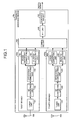
- FIG. 1 is a functional block diagram of the configuration of the diversity receiving device according to the first embodiment.
- a diversity receiving device 10a according to the first embodiment has, for example, four branches that include a first branch 100a, a second branch 200a (not shown), a third branch 300a (not shown), and a fourth branch 400a to receive OFDM modulated signals in the diversity scheme.
- the first to the fourth branches 100a to 400a have the same configuration; therefore, only the configuration of the first branch 100a is described below as the representative.
- the number of branches is not limited to four, i.e., the first to the fourth branches 100a to 400a, and can take any number that is larger than one.
- a tuner unit 101 receives an OFDM modulated signal via an antenna 108, and an AD converting unit 102 converts the received signal from an analog signal into a digital signal.
- An orthogonal demodulating unit 103 detects a complex baseband signal that is a complex of an I channel and a Q channel from the digital OFDM modulated signal by shifting the phase by a quarter.
- the complex baseband signal that is detected by the orthogonal demodulating unit 103 is input to both a phase-difference correcting unit 104 and an SN-ratio calculating unit 105.
- the phase-difference correcting unit 104 calculates a phase-difference correcting signal using delayed waves and ghost waves included in the complex baseband signal to correct a phase difference in the complex baseband signal and sends, after correcting the complex baseband signal using the phase-difference correcting signal, the corrected complex baseband signal to a combining unit 500 at a subsequent stage.
- the SN-ratio calculating unit 105 is an SN-ratio calculating unit that calculates, in the first branch 100a, the SN ratio of the received signal.
- the SN ratio is calculated as follows.
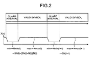
- X(n) that is defined by the following equation is calculated first, in which S(I, i) is an output of a signal that is an i-th sample of an I-th symbol of the received signal, n is the sample number of an n-th sample of the I-th symbol, N is a width of a moving average indicative of the number of samples smaller than Ng that is the number of samples of the guard interval of the I-th symbol, N u is the number of samples of the valid symbol.
- SN(I) that is the SN ratio of the I-th symbol is calculated using the following equation, in which N max (I) is the maximum value of the I-th symbol and N min (I) is the minimum value of the I-th symbol.
- N max (I) is the maximum value of the I-th symbol
- N min (I) is the minimum value of the I-th symbol.
- the outline of calculation of the SN(I) is shown in FIG. 2 .
- N min (I) is the denominator of the equation for calculating SN(I)
- the SN ratio that is affected only by Additive White Gaussian Noise (AWGN) and free from the effect of multipath is calculated. This enables elimination of, especially, the effect of preceding ghosts that arrive earlier than the dominant waves.
- AWGN Additive White Gaussian Noise
- each of the sample i of S(I, i+N u )-S(I, i) appears as shown in FIG. 3(a) .
- the waveform of S(I, i+N u )-S(I, i) appears as shown in FIG. 3(b) due to the effect of delayed waves and ghost waves onto the guard intervals.
- both the numerator and the denominator of the equation for calculating the SN ratio are calculated based on the theory using the same equation for calculating X(n); therefore, it is possible to reduce the scale of the logic circuit that calculates the SN ratio.
- "S" and "N" of the SN ratio i.e., the output of the signal and the noise output are needed to be calculated individually and moreover a square (second-order) calculation using S(I, i+N u )-S(I, i) and S(I, i) is needed to calculate these values; therefore, a large computing amount is needed. This leads to a logical circuit having a larger scale or a more complicated configuration.
- a large computing amount leads to a long computing time.
- Use of the logical circuit that performs the calculating manner described in the first embodiment leads to scale reduction, simplification, and calculating-time reduction of the logical circuit, because the simple first-order calculation using S(I, i+N u )-S(I, i) and S(I, i) is performed.
- N is defined by the following equation:
- both the complex baseband signal after the phase difference is corrected using the phase-difference correcting signal and the SN ratio of the complex baseband signal that is received by the first branch 100a are sent from the first branch 100a to the combining unit 500.
- both the complex baseband signal after the phase difference is corrected using the phase-difference correcting signal and the SN ratio of the complex baseband signal that is received by each branch are sent from the second to the fourth branches 200a to 400a to the combining unit 500.
- the combining unit 500 weights the complex baseband signals that are corrected using the phase-difference correcting signals by the branches depending on the respective SN ratios and combines the weighted signals, thereby creating the input signal.
- a weighting coefficient W j that is used for weighting the complex baseband signal of a j-th branch (1 ⁇ j ⁇ 4) is calculated using the following equation, in which SN j is the SN ratio of the j-th branch:
- SI is created using the weighting coefficient W j by the following equation. That is, SI is calculated using the following equation, in which S j is an output of the signal from the j-th branch and N j is a noise output:
- the weighting coefficient W j is calculated using the above Equation (12) so as to set SN post to a maximum value. This enhances the quality of the input signal SI after the combining to a high level.
- An FFT unit 600 performs a Fast Fourier Transform process on the input signal SI that is created by the combining unit 500.
- the Fast Fourier Transformed SI is demodulated by a demodulating unit 700 and the digital signal is then output.
- FIG. 5 is a functional block diagram of the configuration of the diversity receiving device according to the second ) embodiment.
- a diversity receiving device 10b according to the second embodiment has, for example, four branches that include a first branch 100b, a second branch 200b, a third branch 300b, and a fourth branch 400b to receive OFDM modulated signals in the diversity scheme, as the diversity receiving device 10a according to the first embodiment has the four branches.
- the first to the fourth branches 100b to 400b have the same configuration; therefore, only the configuration of the first branch 100b is described below as the representative.
- the number of branches is not limited to four, i.e., the first to the fourth branches 100b to 400b, and can take any number that is larger than one.
- the configuration of the first branch 100b is described below only about a part that is different from that of the diversity receiving device 10a according to the first embodiment.
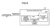
- the complex baseband signal that is detected by the orthogonal demodulating unit 103 of the first branch 100b is input to each of the phase-difference correcting unit 104, the SN-ratio calculating unit 105, and a multipath detecting unit 106, in parallel.
- the SN-ratio calculating unit 105 of the first branch 100b calculates the SN ratio of the complex baseband signal that is received from the orthogonal demodulating unit 103.
- the manner of calculating the SN ratio is the same as the SN-ratio calculating manner performed by the SN-ratio calculating unit 105 in the first embodiment.
- the SN ratio calculated by the SN-ratio calculating unit 105 is sent to both the combining unit 500 at the subsequent stage and the multipath detecting unit 106.
- a guard-interval-position identifying unit 106b1 of the multipath detecting unit 106 identifies a period of the guard interval of the I-th symbol using X Ng (n) that is defined by the above Equation (6). It means that, in X(n) expressed by Equation (9) in the first embodiment, the width of the moving average N corresponds to the number of samples of the guard interval.
- a multipath-noise calculating unit 106a1 of the multipath detecting unit 106 calculates the multipath noise using information about X(n) received from the SN-ratio calculating unit 105 and information about a position of the guard interval received from the guard-interval-position identifying unit 106b1.
- the waveform of S(I, i+N u )-S(I, i) appears as shown in FIG. 7(a) .
- the width of the moving average N is Ng/8
- the graph of X(n) appears as shown in FIG. 7(b) . That is, if multipath noise caused by the delayed waves is present, X(n) keeps equal to or larger than a predetermined value from the start position of the guard interval in the time axial direction. If multipath noise caused by the preceding ghosts is present, X(n) keeps equal to or larger than the predetermined value from the end position of the guard interval in the reverse direction with respect to the time axis.
- the end position of the period of the guard interval identified by the guard-interval-position identifying unit 106b1 in the above conditions is the position of the minimum value "min" of X Ng (n) (see FIG. 7(c) ).
- the identification of the end position enables estimation of the position of the guard interval. Differences ⁇ 1 and ⁇ 2 between a value of X(n) within the period of the guard interval when affected by the multipath noise and the value N min (I) are calculated (see FIG. 7(b) ). If the differences are equal to or larger than a predetermined threshold, the combining unit 500 at the subsequent stage is notified of the fact.
- the combining unit 500 adjusts the weighting coefficient, which is used to create the input signal SI by combining the complex baseband signals that are the products of the received signals diversity-received by the first branch 100b, to a value equal to or smaller than a predetermined value.
- the combining unit 500 adjusts the weighting coefficient W j that is calculated using Equation (12) described in the first embodiment to a value equal to or smaller than the predetermined value or decreases the coefficient W j to a predetermined percentage.
- the multipath is detected, and the weighting is performed appropriately depending on the magnitude of the delayed waves and the preceding ghost waves (DU ratio, Desired Signal to Undesired Signal Ratio). This suppresses the effect of the delayed waves and the preceding ghost waves as much as possible and facilitates demodulation of the input signal SI after the combining performed by the combining unit 500.
- the multipath noise can be corrected by the phase-difference correcting unit 104 in some cases; however, in cases where the DU ratio is too large, the multipath noise cannot be corrected sufficiently or it is impossible to correct the multipath noise.
- the multipath detecting unit 106 (especially, the multipath-noise calculating unit 106a1) decreases the weighting coefficient of the complex baseband signal so that the effect of the delayed waves and the preceding ghost waves is suppressed as much as possible, which facilitates the demodulation of the input signal SI after the combining performed by the combining unit 500.
- FIG. 8 is a functional block diagram of the configuration of the diversity receiving device according to the third embodiment.
- a diversity receiving device 10c according to the third embodiment has, for example, four branches that include a first branch 100c, a second branch 200c (not shown), a third branch 300c (not shown), and a fourth branch 400c to receive OFDM modulated signals in the diversity scheme.
- the first to the fourth branches 100c to 400c have the same configuration; therefore, only the configuration of the first branch 100c is described below as the representative.
- the number of branches is not limited four, i.e., the first to the fourth branches 100c to 400c, and can take any number that is larger than one.
- the tuner unit 101 receives an OFDM modulated signal via the antenna 108, and the AD converting unit 102 converts the received signal from an analog signal into a digital signal.
- the orthogonal demodulating unit 103 detects a complex baseband signal that is a complex of an I channel and a Q channel from the digital OFDM modulated signal by shifting the phase by a quarter.
- the complex baseband signal that is detected by the orthogonal demodulating unit 103 is input to each of the phase-difference correcting unit 104, a first low-pass filtering unit 105a, a second low-pass filtering unit 105b, a third low-pass filtering unit 105c, a fourth low-pass filtering unit 105d, and a fifth low-pass filtering unit 105e, in parallel.
- the number of low-pass filters is not limited five, i.e., the first to the fifth low-pass filtering units 105a to 105e, and can take any number that is larger than one. It is allowable to use band-pass filters instead of low-pass filters.
- the phase-difference correcting unit 104 calculates a phase-difference correcting signal using delayed waves and ghost waves included in the complex baseband signal to correct a phase difference in the complex baseband signal and sends, after correcting the complex baseband signal using the phase-difference correcting signal, the corrected complex baseband signal to the combining unit 500 at the subsequent stage.
- the first low-pass filtering unit 105a cuts off a signal having a first particular frequency of the complex baseband signal and sends it to a first SN-ratio calculating unit 106a.
- the second low-pass filtering unit 105b cuts off a signal having a second particular frequency of the complex baseband signal and sends it to a second SN-ratio calculating unit 106b;
- the third low-pass filtering unit 105c cuts off a signal having a third particular frequency of the complex baseband signal and sends it to a third SN-ratio calculating unit 106c;
- the fourth low-pass filtering unit 105d cuts off a signal having a fourth particular frequency of the complex baseband signal and sends it to a fourth SN-ratio calculating unit 106d;
- the fifth low-pass filtering unit 105e cuts off a signal having a fourth particular frequency of the complex baseband signal and sends it to a fifth SN-ratio calculating unit 106e. It is noted that the first
- the first SN-ratio calculating unit 106a to the fifth SN-ratio calculating unit 106e are a plurality of SN-ratio calculating units provided to the first low-pass filtering unit 105a to the fifth low-pass filtering unit 105e, respectively in the first branch 100c.
- the SN ratios are calculated on the low-pass filtering unit basis using the guard interval of the time signal from the complex baseband signals after the cutting-off by the low-pass filtering units.
- the SN ratios are calculated on the low-pass filtering unit basis as follows.
- X(n) that is defined by the following equation is calculated first, in which S(I, i) is an output of a signal that is an i-th sample of an I-th symbol of the received signal, n is the sample number of an n-th sample of the I-th symbol, N is a width of a moving average indicative of the number of samples smaller than Ng that is the number of samples of the guard interval of the I-th symbol, N u is the number of samples of the valid symbol:
- N max (I) is the maximum value of the I-th symbol
- N min (I) is the minimum value of the I-th symbol.
- N min (I) is the noise component of the particular frequency that is cut off by the low-pass filter. The outline of calculation of the SN(I) is shown in FIG. 9 .
- the SN ratio can be calculated using a conventional method by the following equation.
- N(I) is calculated first using the following equation, in which "I" represents the I-th symbol of the received signal as described above.
- SN(I) that is the SN ratio of the I-th symbol of the received signal is calculated by the following equation using N(I) that is calculated using Equation (21) and S(I) that is calculated using Equation (22):
- the first branch 100c includes a particular-frequency noise correcting unit 107.
- the particular-frequency noise correcting unit 107 estimates the noise of the particular frequency using N min (I) of each particular frequency that is calculated by the first SN-ratio calculating unit 106a to the fifth SN-ratio calculating unit 106e using the above Equation (18) and eliminates the effect thereof so that the input signal, which is created by combining the weighted signals by the combining unit 500 at the subsequent stage, can be demodulated easily.
- the first low-pass filtering unit 105a is abbreviated as LP1
- the second low-pass filtering unit 105b is abbreviated as LP2
- the third low-pass filtering unit 105c is abbreviated as LP3
- the fourth low-pass filtering unit 105d is abbreviated as LP4
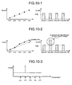
- the fifth low-pass filtering unit 105e is abbreviated as LP5, "N min (I) of the complex baseband signal after the cutting-off by LP1" ⁇ "N min( I) of the complex baseband signal after the cutting-off by LP2" ⁇ "N min (I) of the complex baseband signal after the cutting-off by LP3" ⁇ "N min (I) of the complex baseband signal after the cutting-off by LP4" ⁇ "N min (I) of the complex baseband signal after the cutting-off by LP5" and the values of N min (I) are in proportional relations are then satisfied.
- the values of LP2-LP1, LP3-LP2, LP4-LP3, and LP5-LP4 are variable; therefore, the slope of the graph that is drawn by plotting the points of N min (I) is variable.
- the slope of the straight line between N min (I) of LP2 and N min (I) of LP3 is larger than the slopes of the straight lines between the points of N min (I) of the other low-pass filters. Due to this, it is estimated as shown in FIG. 10-3 that a particular frequency noise is present in the complex baseband signal after the cutting-off by the second low-pass filtering unit 105b.
- the particular-frequency noise correcting unit 107 corrects the particular frequency noise in the complex baseband signal that is estimated in the above manner. For example, the excessive value of LP3-LP2 shown in FIG. 10-2 can be eliminated from the other values of LP2-LP1, LP4-LP3, and LP5-LP4. The particular frequency noise in the complex baseband signal is corrected using the value of LP3-LP2 after the excessive part is eliminated in this manner.
- the particular-frequency noise correcting unit 107 calculates the SN ratio after the particular frequency noise is eliminated using the above Equation (20) or the above Equation (23) and sets it as the SN ratio of the first branch 100C. Both the complex baseband signal after the particular frequency noise is corrected (eliminated) and the SN ratio after the particular frequency noise is eliminated are sent to the combining unit 500 at the subsequent stage.
- the complex baseband signal after the phase difference is corrected using the phase-difference correcting signal and the SN ratio of the complex baseband signal after the particular frequency noise is corrected are sent from the first branch 100c to the combining unit 500.
- the complex baseband signal after the phase difference is corrected using the phase-difference correcting signal and the SN ratio of the complex baseband signal after the particular frequency noise is corrected at each branch are sent from the second to the fourth branches 200c to 400c to the combining unit 500 in the same manner.
- the combining unit 500 weights the complex baseband signals that are corrected using the phase-difference correcting signals by the branches depending on the respective SN ratios and combines the weighted signals, thereby creating the input signal.
- the FFT unit 600 performs a Fast Fourier Transform process on the input signal that is created by the combining unit 500.
- the Fast Fourier Transformed SI is demodulated by the demodulating unit 700 and the digital signal is then output.
- the particular frequency noise is eliminated using the frequency-based distribution of the minimum values N min (I) in the I-th symbol of the received signal that is cut off into frequency-based segments
- the configuration is not limited thereto. It is allowable to use the SN ratio SN(I) instead of N min (I). In this case, an increase of the SN ratio to the frequency-based segment is a reflection of the frequency property of S(I). If the frequency property of S(I) has been grasped in advance, the particular frequency noise of the received signal can be corrected by calculating the difference using the frequency property.
- FIG. 11 is a block diagram of the example in which the diversity receiving device shown in FIG. 8 is used in the digital television receiving apparatus.
- a digital signal based on a received wave is input from a diversity receiving device 10 to a backend device 801.
- the backend device 801 includes a DSP (Digital Signal Processor) 801a, a video buffer 801b, and a DAC (Digital to Analog Converter)+VCXO (Voltage Controlled Xtal Oscillator) 801c.
- the DAC is a digital-to-analog converter circuit that converts a digital signal into an analog signal.
- the VCXO is a crystal oscillator that can change the frequency depending on the voltage.
- the DAC+VCXO 801c is a digital-to-analog converter circuit that is controlled by a crystal oscillator.
- various control circuits in the diversity receiving device 10 and the DSP 801a are controlled by the crystal oscillator of the DAC+VCXO 801c via a predetermined IIC (Inter-IC) bus (not shown).
- the DAC+VCXO 801c receives a synchronization control signal from the DSP 801a via a predetermined IIC bus.
- the DSP 801a demodulates a digital video signal based on video compression standards, such as H.264, MPEG (Moving Picture Expert Group) and demodulates a digital audio signal based on audio compression standards, such as AAC (Advanced Audio Coding). Moreover, the DSP 801a controls the backend device 801.
- video compression standards such as H.264, MPEG (Moving Picture Expert Group)
- AAC Advanced Audio Coding
- the DSP 801a has an OSD (On-Screen Display) function for controlling an operation screen of the digital television receiving apparatus 800 appearing on a predetermined display.
- the DSP 801a encodes the video data and performs Pulse Width Modulation (PWM) with the audio data.
- PWM Pulse Width Modulation
- the DSP 801a is connected to a host computer via a predetermined interface.
- the host computer displays, by the above-described OSD function, an operation screen for selection of video and/or audio in the digital television receiving apparatus 800 and sends information about an instruction received via the operation screen to the DSP 801a.
- the DSP 801a temporarily loads the encoded video data on the video buffer 801b and sends the data in the form of an analog signal supported by NTSC (National Television Standards Committee) to a display device (not shown) via a predetermined interface.
- the DSP 801a sends the pulse-width modulated audio data to the DAC+VCXO 801c.
- the DAC+VCXO 801c converts the audio data that is received from the DSP 801a from the digital signal into the analog signal, separates it into an L channel and an R channel, and outputs it to a speaker device (not shown) via a corresponding interface.
- the diversity receiving device 10a according to the first embodiment and the diversity receiving device 10b according to the second embodiment are used in the above-described digital television receiving apparatus 800, it is possible to calculate the SN ratio of the received wave using a simpler circuit configuration/process in such a manner that the SN ratio of the input signal that is created by combining the diversity-received signals is set to a maximum value. Moreover, because the effect of the delayed waves and the preceding ghost waves and the noise of the particular frequency is suppressed as much as possible, the quality of the input signal is enhanced, which makes it possible to display clear image and output clear voices using the received waves and facilitate the demodulation of the input signal that is created by combining the diversity-received signals.
- use of the diversity receiving device 10c according to the third embodiment in the above-described digital television receiving apparatus 800 enables eliminating the noise of the particular frequency contained in the received wave on the received signal level basis, which enables displaying of clear image and outputting of clear voices based on the received waves.
- first to the third embodiments It is allowable to implement a combination of the above-described first to the third embodiments.
- the present invention is not limited to the first embodiment, the second embodiment, and the third embodiment.
- the present invention can be implemented according to various different embodiments within the scope of the technical idea described in claims.
- the effects of the first to the third embodiments are not limited thereto.
- the constituent elements of the device shown in the drawings are merely conceptual, and need not be physically configured as illustrated.
- the constituent elements, as a whole or in part, can be separated or integrated either functionally or physically based on various types of loads or use conditions.
- the process functions performed by the device are entirely or partially realized by the CPU or computer programs that are analyzed and executed by the CPU, or realized as hardware by wired logic.
- a diversity receiving device, a diversity receiving method, and a digital television receiving apparatus are implemented without increasing the complexity of the configuration of a circuit that calculates an SN ratio (or CN ratio), and particularly suitable for increasing the quality of the receiving results using a preferable SN ratio (or CN ratio) that is obtained after effect of delayed waves and ghosts caused by multipath and noise of a particular frequency are eliminated.
Landscapes
- Engineering & Computer Science (AREA)
- Computer Networks & Wireless Communication (AREA)
- Signal Processing (AREA)
- Quality & Reliability (AREA)
- Radio Transmission System (AREA)
Applications Claiming Priority (3)
| Application Number | Priority Date | Filing Date | Title |
|---|---|---|---|
| JP2007226678A JP4708400B2 (ja) | 2007-08-31 | 2007-08-31 | ダイバシティ受信装置、ダイバシティ受信方法およびデジタルテレビジョン受信装置 |
| JP2007253312A JP4551432B2 (ja) | 2007-09-28 | 2007-09-28 | ダイバシティ受信装置およびダイバシティ受信方法 |
| PCT/JP2008/065698 WO2009028711A1 (ja) | 2007-08-31 | 2008-09-01 | ダイバシティ受信装置、ダイバシティ受信方法およびデジタルテレビジョン受信装置 |
Publications (4)
| Publication Number | Publication Date |
|---|---|
| EP2200201A1 true EP2200201A1 (de) | 2010-06-23 |
| EP2200201A4 EP2200201A4 (de) | 2015-06-17 |
| EP2200201B1 EP2200201B1 (de) | 2017-01-11 |
| EP2200201B8 EP2200201B8 (de) | 2017-08-09 |
Family
ID=40387414
Family Applications (1)
| Application Number | Title | Priority Date | Filing Date |
|---|---|---|---|
| EP08828735.4A Not-in-force EP2200201B8 (de) | 2007-08-31 | 2008-09-01 | Diversitätsempfangsvorrichtung, diversitätsempfangsverfahren und digitaler fernsehempfangsgerät |
Country Status (3)
| Country | Link |
|---|---|
| EP (1) | EP2200201B8 (de) |
| CN (1) | CN101790862B (de) |
| WO (1) | WO2009028711A1 (de) |
Family Cites Families (11)
| Publication number | Priority date | Publication date | Assignee | Title |
|---|---|---|---|---|
| US5351274A (en) * | 1993-08-20 | 1994-09-27 | General Electric Company | Post detection selection combining diversity receivers for mobile and indoor radio channels |
| JP3377361B2 (ja) * | 1996-04-12 | 2003-02-17 | 日本放送協会 | ダイバーシチ受信装置 |
| JP3311237B2 (ja) | 1996-05-21 | 2002-08-05 | 沖電気工業株式会社 | ダイバーシティ受信回路 |
| JPH10256967A (ja) * | 1997-03-13 | 1998-09-25 | Nippon Telegr & Teleph Corp <Ntt> | 検波後ダイバーシチ受信回路 |
| JP3550307B2 (ja) * | 1998-12-16 | 2004-08-04 | シャープ株式会社 | 受信機及び受信方法 |
| JP3449281B2 (ja) * | 1999-02-26 | 2003-09-22 | 株式会社豊田中央研究所 | マルチキャリア受信装置用同期回路及びマルチキャリア受信装置 |
| JP3857009B2 (ja) * | 2000-02-15 | 2006-12-13 | 三菱電機株式会社 | マルチキャリア無線受信装置およびマルチキャリア無線伝送装置 |
| JP4317335B2 (ja) | 2001-08-06 | 2009-08-19 | 日本放送協会 | ダイバーシティ受信機 |
| US20040081131A1 (en) * | 2002-10-25 | 2004-04-29 | Walton Jay Rod | OFDM communication system with multiple OFDM symbol sizes |
| JP4364820B2 (ja) | 2005-03-09 | 2009-11-18 | 株式会社メガチップス | Ofdmダイバーシティ受信装置 |
| JP2007208748A (ja) * | 2006-02-02 | 2007-08-16 | Sharp Corp | Ofdm復調装置、ofdm復調方法、プログラム及びコンピュータ読み取り可能な記録媒体 |
-
2008
- 2008-09-01 WO PCT/JP2008/065698 patent/WO2009028711A1/ja not_active Ceased
- 2008-09-01 EP EP08828735.4A patent/EP2200201B8/de not_active Not-in-force
- 2008-09-01 CN CN2008801048886A patent/CN101790862B/zh not_active Expired - Fee Related
Non-Patent Citations (1)
| Title |
|---|
| See references of WO2009028711A1 * |
Also Published As
| Publication number | Publication date |
|---|---|
| EP2200201B8 (de) | 2017-08-09 |
| CN101790862B (zh) | 2013-03-27 |
| EP2200201B1 (de) | 2017-01-11 |
| WO2009028711A1 (ja) | 2009-03-05 |
| CN101790862A (zh) | 2010-07-28 |
| EP2200201A4 (de) | 2015-06-17 |
Similar Documents
| Publication | Publication Date | Title |
|---|---|---|
| US7535820B2 (en) | OFDM signal receiving apparatus and OFDM signal receiving method | |
| US20100309383A1 (en) | Reception device, integrated circuit, digital television receiver, reception method, and reception program | |
| EP2693647B1 (de) | Empfangsvorrichtung, empfangsverfahren, programm und empfangssystem | |
| US8175204B2 (en) | Receiving device, signal processing method, and program | |
| CN103404038B (zh) | 接收装置、接收方法和程序 | |
| EP2200201B1 (de) | Diversitätsempfangsvorrichtung, diversitätsempfangsverfahren und digitaler fernsehempfänger | |
| US8924451B2 (en) | Reception apparatus, reception method and program for single carrier and multicarriers data | |
| US8995589B1 (en) | Channel estimation in a pilot assisted OFDM system | |
| US20060146690A1 (en) | Methods, circuits and computer program products for estimating frequency domain channel in a DVB-T receiver using transform domain complex filtering | |
| US20110268172A1 (en) | Receiver apparatus and receiving method | |
| JP4551432B2 (ja) | ダイバシティ受信装置およびダイバシティ受信方法 | |
| US7787059B2 (en) | Digital television receiver | |
| EP1528741A1 (de) | Verfahren und Vorrichtung für OFDM Diversity-Empfang | |
| JP4708400B2 (ja) | ダイバシティ受信装置、ダイバシティ受信方法およびデジタルテレビジョン受信装置 | |
| EP1804388A1 (de) | Digitale broadcast-empfangseinrichtung | |
| EP2224610A1 (de) | Diversity-empfangseinrichtung und diversity-empfangsverfahren | |
| JP5525262B2 (ja) | 復調装置及び受信装置、並びに復調方法 | |
| JP4621143B2 (ja) | ダイバーシティ受信装置 | |
| JP2011114435A (ja) | ノイズ低減機能付受信装置、ノイズ低減方法、プログラムおよび集積回路 | |
| EP1750436A1 (de) | Empfangsgerät | |
| US8175176B2 (en) | FFT window spread generating method | |
| JP2008004976A (ja) | 信号等化装置、受信装置、信号等化方法および信号等化プログラム | |
| KR20070073606A (ko) | 디지털 무선 신호를 최적으로 디모듈레이팅 및 디코딩하기위한 수신기 및 방법 | |
| JP2003008543A (ja) | データ伝送装置 | |
| JP2012186615A (ja) | 受信装置、受信方法、およびプログラム |
Legal Events
| Date | Code | Title | Description |
|---|---|---|---|
| PUAI | Public reference made under article 153(3) epc to a published international application that has entered the european phase |
Free format text: ORIGINAL CODE: 0009012 |
|
| 17P | Request for examination filed |
Effective date: 20100331 |
|
| AK | Designated contracting states |
Kind code of ref document: A1 Designated state(s): AT BE BG CH CY CZ DE DK EE ES FI FR GB GR HR HU IE IS IT LI LT LU LV MC MT NL NO PL PT RO SE SI SK TR |
|
| AX | Request for extension of the european patent |
Extension state: AL BA MK RS |
|
| DAX | Request for extension of the european patent (deleted) | ||
| RIC1 | Information provided on ipc code assigned before grant |
Ipc: H04L 1/20 20060101ALI20141219BHEP Ipc: H04J 11/00 20060101AFI20141219BHEP Ipc: H04L 27/26 20060101ALI20141219BHEP Ipc: H04B 7/08 20060101ALI20141219BHEP |
|
| RA4 | Supplementary search report drawn up and despatched (corrected) |
Effective date: 20150518 |
|
| RIC1 | Information provided on ipc code assigned before grant |
Ipc: H04J 11/00 20060101AFI20150511BHEP Ipc: H04B 7/08 20060101ALI20150511BHEP Ipc: H04L 27/26 20060101ALI20150511BHEP Ipc: H04L 1/20 20060101ALI20150511BHEP |
|
| RIC1 | Information provided on ipc code assigned before grant |
Ipc: H04L 27/26 20060101ALI20160728BHEP Ipc: H04J 11/00 20060101AFI20160728BHEP Ipc: H04B 7/08 20060101ALI20160728BHEP Ipc: H04L 1/20 20060101ALI20160728BHEP |
|
| GRAP | Despatch of communication of intention to grant a patent |
Free format text: ORIGINAL CODE: EPIDOSNIGR1 |
|
| INTG | Intention to grant announced |
Effective date: 20160908 |
|
| GRAS | Grant fee paid |
Free format text: ORIGINAL CODE: EPIDOSNIGR3 |
|
| GRAA | (expected) grant |
Free format text: ORIGINAL CODE: 0009210 |
|
| AK | Designated contracting states |
Kind code of ref document: B1 Designated state(s): AT BE BG CH CY CZ DE DK EE ES FI FR GB GR HR HU IE IS IT LI LT LU LV MC MT NL NO PL PT RO SE SI SK TR |
|
| REG | Reference to a national code |
Ref country code: GB Ref legal event code: FG4D |
|
| REG | Reference to a national code |
Ref country code: CH Ref legal event code: EP |
|
| REG | Reference to a national code |
Ref country code: AT Ref legal event code: REF Ref document number: 862138 Country of ref document: AT Kind code of ref document: T Effective date: 20170115 |
|
| REG | Reference to a national code |
Ref country code: IE Ref legal event code: FG4D |
|
| REG | Reference to a national code |
Ref country code: DE Ref legal event code: R096 Ref document number: 602008048385 Country of ref document: DE |
|
| GRAT | Correction requested after decision to grant or after decision to maintain patent in amended form |
Free format text: ORIGINAL CODE: EPIDOSNCDEC |
|
| REG | Reference to a national code |
Ref country code: LT Ref legal event code: MG4D |
|
| REG | Reference to a national code |
Ref country code: NL Ref legal event code: MP Effective date: 20170111 |
|
| REG | Reference to a national code |
Ref country code: AT Ref legal event code: MK05 Ref document number: 862138 Country of ref document: AT Kind code of ref document: T Effective date: 20170111 |
|
| PG25 | Lapsed in a contracting state [announced via postgrant information from national office to epo] |
Ref country code: NL Free format text: LAPSE BECAUSE OF FAILURE TO SUBMIT A TRANSLATION OF THE DESCRIPTION OR TO PAY THE FEE WITHIN THE PRESCRIBED TIME-LIMIT Effective date: 20170111 |
|
| PG25 | Lapsed in a contracting state [announced via postgrant information from national office to epo] |
Ref country code: LT Free format text: LAPSE BECAUSE OF FAILURE TO SUBMIT A TRANSLATION OF THE DESCRIPTION OR TO PAY THE FEE WITHIN THE PRESCRIBED TIME-LIMIT Effective date: 20170111 Ref country code: FI Free format text: LAPSE BECAUSE OF FAILURE TO SUBMIT A TRANSLATION OF THE DESCRIPTION OR TO PAY THE FEE WITHIN THE PRESCRIBED TIME-LIMIT Effective date: 20170111 Ref country code: HR Free format text: LAPSE BECAUSE OF FAILURE TO SUBMIT A TRANSLATION OF THE DESCRIPTION OR TO PAY THE FEE WITHIN THE PRESCRIBED TIME-LIMIT Effective date: 20170111 Ref country code: IS Free format text: LAPSE BECAUSE OF FAILURE TO SUBMIT A TRANSLATION OF THE DESCRIPTION OR TO PAY THE FEE WITHIN THE PRESCRIBED TIME-LIMIT Effective date: 20170511 Ref country code: GR Free format text: LAPSE BECAUSE OF FAILURE TO SUBMIT A TRANSLATION OF THE DESCRIPTION OR TO PAY THE FEE WITHIN THE PRESCRIBED TIME-LIMIT Effective date: 20170412 Ref country code: NO Free format text: LAPSE BECAUSE OF FAILURE TO SUBMIT A TRANSLATION OF THE DESCRIPTION OR TO PAY THE FEE WITHIN THE PRESCRIBED TIME-LIMIT Effective date: 20170411 |
|
| PG25 | Lapsed in a contracting state [announced via postgrant information from national office to epo] |
Ref country code: AT Free format text: LAPSE BECAUSE OF FAILURE TO SUBMIT A TRANSLATION OF THE DESCRIPTION OR TO PAY THE FEE WITHIN THE PRESCRIBED TIME-LIMIT Effective date: 20170111 Ref country code: SE Free format text: LAPSE BECAUSE OF FAILURE TO SUBMIT A TRANSLATION OF THE DESCRIPTION OR TO PAY THE FEE WITHIN THE PRESCRIBED TIME-LIMIT Effective date: 20170111 Ref country code: LV Free format text: LAPSE BECAUSE OF FAILURE TO SUBMIT A TRANSLATION OF THE DESCRIPTION OR TO PAY THE FEE WITHIN THE PRESCRIBED TIME-LIMIT Effective date: 20170111 Ref country code: PL Free format text: LAPSE BECAUSE OF FAILURE TO SUBMIT A TRANSLATION OF THE DESCRIPTION OR TO PAY THE FEE WITHIN THE PRESCRIBED TIME-LIMIT Effective date: 20170111 Ref country code: BG Free format text: LAPSE BECAUSE OF FAILURE TO SUBMIT A TRANSLATION OF THE DESCRIPTION OR TO PAY THE FEE WITHIN THE PRESCRIBED TIME-LIMIT Effective date: 20170411 Ref country code: ES Free format text: LAPSE BECAUSE OF FAILURE TO SUBMIT A TRANSLATION OF THE DESCRIPTION OR TO PAY THE FEE WITHIN THE PRESCRIBED TIME-LIMIT Effective date: 20170111 Ref country code: PT Free format text: LAPSE BECAUSE OF FAILURE TO SUBMIT A TRANSLATION OF THE DESCRIPTION OR TO PAY THE FEE WITHIN THE PRESCRIBED TIME-LIMIT Effective date: 20170511 |
|
| REG | Reference to a national code |
Ref country code: DE Ref legal event code: R097 Ref document number: 602008048385 Country of ref document: DE |
|
| PG25 | Lapsed in a contracting state [announced via postgrant information from national office to epo] |
Ref country code: EE Free format text: LAPSE BECAUSE OF FAILURE TO SUBMIT A TRANSLATION OF THE DESCRIPTION OR TO PAY THE FEE WITHIN THE PRESCRIBED TIME-LIMIT Effective date: 20170111 Ref country code: IT Free format text: LAPSE BECAUSE OF FAILURE TO SUBMIT A TRANSLATION OF THE DESCRIPTION OR TO PAY THE FEE WITHIN THE PRESCRIBED TIME-LIMIT Effective date: 20170111 Ref country code: RO Free format text: LAPSE BECAUSE OF FAILURE TO SUBMIT A TRANSLATION OF THE DESCRIPTION OR TO PAY THE FEE WITHIN THE PRESCRIBED TIME-LIMIT Effective date: 20170111 Ref country code: SK Free format text: LAPSE BECAUSE OF FAILURE TO SUBMIT A TRANSLATION OF THE DESCRIPTION OR TO PAY THE FEE WITHIN THE PRESCRIBED TIME-LIMIT Effective date: 20170111 Ref country code: CZ Free format text: LAPSE BECAUSE OF FAILURE TO SUBMIT A TRANSLATION OF THE DESCRIPTION OR TO PAY THE FEE WITHIN THE PRESCRIBED TIME-LIMIT Effective date: 20170111 |
|
| PLBE | No opposition filed within time limit |
Free format text: ORIGINAL CODE: 0009261 |
|
| STAA | Information on the status of an ep patent application or granted ep patent |
Free format text: STATUS: NO OPPOSITION FILED WITHIN TIME LIMIT |
|
| PG25 | Lapsed in a contracting state [announced via postgrant information from national office to epo] |
Ref country code: DK Free format text: LAPSE BECAUSE OF FAILURE TO SUBMIT A TRANSLATION OF THE DESCRIPTION OR TO PAY THE FEE WITHIN THE PRESCRIBED TIME-LIMIT Effective date: 20170111 |
|
| 26N | No opposition filed |
Effective date: 20171012 |
|
| PG25 | Lapsed in a contracting state [announced via postgrant information from national office to epo] |
Ref country code: SI Free format text: LAPSE BECAUSE OF FAILURE TO SUBMIT A TRANSLATION OF THE DESCRIPTION OR TO PAY THE FEE WITHIN THE PRESCRIBED TIME-LIMIT Effective date: 20170111 |
|
| REG | Reference to a national code |
Ref country code: CH Ref legal event code: PL |
|
| GBPC | Gb: european patent ceased through non-payment of renewal fee |
Effective date: 20170901 |
|
| PG25 | Lapsed in a contracting state [announced via postgrant information from national office to epo] |
Ref country code: MC Free format text: LAPSE BECAUSE OF FAILURE TO SUBMIT A TRANSLATION OF THE DESCRIPTION OR TO PAY THE FEE WITHIN THE PRESCRIBED TIME-LIMIT Effective date: 20170111 |
|
| REG | Reference to a national code |
Ref country code: IE Ref legal event code: MM4A |
|
| REG | Reference to a national code |
Ref country code: BE Ref legal event code: MM Effective date: 20170930 |
|
| PG25 | Lapsed in a contracting state [announced via postgrant information from national office to epo] |
Ref country code: LU Free format text: LAPSE BECAUSE OF NON-PAYMENT OF DUE FEES Effective date: 20170901 |
|
| REG | Reference to a national code |
Ref country code: FR Ref legal event code: ST Effective date: 20180531 |
|
| PG25 | Lapsed in a contracting state [announced via postgrant information from national office to epo] |
Ref country code: IE Free format text: LAPSE BECAUSE OF NON-PAYMENT OF DUE FEES Effective date: 20170901 Ref country code: LI Free format text: LAPSE BECAUSE OF NON-PAYMENT OF DUE FEES Effective date: 20170930 Ref country code: CH Free format text: LAPSE BECAUSE OF NON-PAYMENT OF DUE FEES Effective date: 20170930 Ref country code: GB Free format text: LAPSE BECAUSE OF NON-PAYMENT OF DUE FEES Effective date: 20170901 |
|
| PG25 | Lapsed in a contracting state [announced via postgrant information from national office to epo] |
Ref country code: FR Free format text: LAPSE BECAUSE OF NON-PAYMENT OF DUE FEES Effective date: 20171002 Ref country code: BE Free format text: LAPSE BECAUSE OF NON-PAYMENT OF DUE FEES Effective date: 20170930 |
|
| PG25 | Lapsed in a contracting state [announced via postgrant information from national office to epo] |
Ref country code: MT Free format text: LAPSE BECAUSE OF NON-PAYMENT OF DUE FEES Effective date: 20170901 |
|
| PG25 | Lapsed in a contracting state [announced via postgrant information from national office to epo] |
Ref country code: HU Free format text: LAPSE BECAUSE OF FAILURE TO SUBMIT A TRANSLATION OF THE DESCRIPTION OR TO PAY THE FEE WITHIN THE PRESCRIBED TIME-LIMIT; INVALID AB INITIO Effective date: 20080901 |
|
| PG25 | Lapsed in a contracting state [announced via postgrant information from national office to epo] |
Ref country code: CY Free format text: LAPSE BECAUSE OF NON-PAYMENT OF DUE FEES Effective date: 20170111 |
|
| PG25 | Lapsed in a contracting state [announced via postgrant information from national office to epo] |
Ref country code: TR Free format text: LAPSE BECAUSE OF FAILURE TO SUBMIT A TRANSLATION OF THE DESCRIPTION OR TO PAY THE FEE WITHIN THE PRESCRIBED TIME-LIMIT Effective date: 20170111 |
|
| PGFP | Annual fee paid to national office [announced via postgrant information from national office to epo] |
Ref country code: DE Payment date: 20200925 Year of fee payment: 13 |
|
| REG | Reference to a national code |
Ref country code: DE Ref legal event code: R082 Ref document number: 602008048385 Country of ref document: DE Representative=s name: HL KEMPNER PATENTANWALT, RECHTSANWALT, SOLICIT, DE |
|
| REG | Reference to a national code |
Ref country code: DE Ref legal event code: R119 Ref document number: 602008048385 Country of ref document: DE |
|
| PG25 | Lapsed in a contracting state [announced via postgrant information from national office to epo] |
Ref country code: DE Free format text: LAPSE BECAUSE OF NON-PAYMENT OF DUE FEES Effective date: 20220401 |