EP2199997A2 - Alarmsystem und Alarmvorrichtung - Google Patents
Alarmsystem und Alarmvorrichtung Download PDFInfo
- Publication number
- EP2199997A2 EP2199997A2 EP09252735A EP09252735A EP2199997A2 EP 2199997 A2 EP2199997 A2 EP 2199997A2 EP 09252735 A EP09252735 A EP 09252735A EP 09252735 A EP09252735 A EP 09252735A EP 2199997 A2 EP2199997 A2 EP 2199997A2
- Authority
- EP
- European Patent Office
- Prior art keywords
- alarm device
- switching
- slave
- master unit
- master
- Prior art date
- Legal status (The legal status is an assumption and is not a legal conclusion. Google has not performed a legal analysis and makes no representation as to the accuracy of the status listed.)
- Ceased
Links
Images


Classifications
-
- G—PHYSICS
- G08—SIGNALLING
- G08B—SIGNALLING OR CALLING SYSTEMS; ORDER TELEGRAPHS; ALARM SYSTEMS
- G08B25/00—Alarm systems in which the location of the alarm condition is signalled to a central station, e.g. fire or police telegraphic systems
- G08B25/01—Alarm systems in which the location of the alarm condition is signalled to a central station, e.g. fire or police telegraphic systems characterised by the transmission medium
- G08B25/10—Alarm systems in which the location of the alarm condition is signalled to a central station, e.g. fire or police telegraphic systems characterised by the transmission medium using wireless transmission systems
-
- G—PHYSICS
- G08—SIGNALLING
- G08B—SIGNALLING OR CALLING SYSTEMS; ORDER TELEGRAPHS; ALARM SYSTEMS
- G08B17/00—Fire alarms; Alarms responsive to explosion
-
- G—PHYSICS
- G08—SIGNALLING
- G08B—SIGNALLING OR CALLING SYSTEMS; ORDER TELEGRAPHS; ALARM SYSTEMS
- G08B25/00—Alarm systems in which the location of the alarm condition is signalled to a central station, e.g. fire or police telegraphic systems
- G08B25/003—Address allocation methods and details
-
- G—PHYSICS
- G08—SIGNALLING
- G08B—SIGNALLING OR CALLING SYSTEMS; ORDER TELEGRAPHS; ALARM SYSTEMS
- G08B25/00—Alarm systems in which the location of the alarm condition is signalled to a central station, e.g. fire or police telegraphic systems
- G08B25/007—Details of data content structure of message packets; data protocols
-
- G—PHYSICS
- G08—SIGNALLING
- G08B—SIGNALLING OR CALLING SYSTEMS; ORDER TELEGRAPHS; ALARM SYSTEMS
- G08B7/00—Signalling systems according to more than one of groups G08B3/00 - G08B6/00; Personal calling systems according to more than one of groups G08B3/00 - G08B6/00
- G08B7/06—Signalling systems according to more than one of groups G08B3/00 - G08B6/00; Personal calling systems according to more than one of groups G08B3/00 - G08B6/00 using electric transmission, e.g. involving audible and visible signalling through the use of sound and light sources
-
- H—ELECTRICITY
- H04—ELECTRIC COMMUNICATION TECHNIQUE
- H04L—TRANSMISSION OF DIGITAL INFORMATION, e.g. TELEGRAPHIC COMMUNICATION
- H04L12/00—Data switching networks
- H04L12/28—Data switching networks characterised by path configuration, e.g. LAN [Local Area Networks] or WAN [Wide Area Networks]
Definitions
- the present invention relates to an alarm system including a master alarm device and at least one slave alarm device which are capable of communication with each other.
- an alarm device for detecting heat or smoke that is generated in a room or the like and issuing an alarm.
- an alarm system including each of such alarm devices provided in respective rooms, in which one of the plurality of alarm devices and others thereof operate as a master unit and slave units, respectively, and perform the alarm operation in synchronization with one another.
- a wireless slave unit used in a specified low power two-way wireless communication system including one wireless master unit and a plurality of wireless slave units, for performing two-way wireless communication with an available frequency band being one wave
- the wireless slave unit including: means for transmitting a declaration message of "communication start”, which declares that communication is to be started, when the communication is started with the wireless master unit in a status where all wireless slave units including the wireless slave unit have no communication with the wireless master unit; means for receiving the declaration message of the "communication start”, which declares that the communication has been started, with regard to any one of wireless slave units excluding the wireless slave unit; means for identifying the received declaration message, and immediately shifting the wireless slave unit into a call standby status indicating that the any one of wireless slave units excluding the wireless slave unit is communicating with the wireless master unit; means for transmitting, at a time of finishing the communication with the wireless master unit, a declaration message of "communication end”, which declares that the communication with the wireless master unit is finished; means for
- the master unit stores and manages terminal information at the time of addition, replacement, deletion, etc. of a slave unit terminal within the alarm system.
- the master unit relays the signal. In this manner, the master unit and the slave units within the alarm system perform an alarm operation in synchronization with one another.
- the frequency of communication performed between the master unit and the slave units increases.
- the number of communication tasks to be processed by the master unit increases, which results in increased current consumption of the master unit. Accordingly, for example, in a case of a master unit powered by a battery, a battery life thereof becomes shorter.
- the master unit by supplying power from an AC power supply, it is possible to operate the master unit without having any concern about the battery level.
- the location where the master unit is installed may be limited depending on the location of the power supply outlet.
- the master unit and the slave unit are products of different configurations, and hence a manufacturing process and an inspection process therefor become complicated, resulting in increased workload. Consequently, manufacturing cost becomes higher.
- the master unit fails to sufficiently perform a function as the alarm device.
- the present invention has been made, and provides an alarm system and an alarm device which are capable of enhancing a fail-safe function by periodically switching an alarm device operating as a master unit.
- An alarm system includes: a master alarm device; and at least one slave alarm device, the master alarm device and the at least one slave alarm device performing transmission and reception therebetween.
- the master alarm device transmits a switching request signal to the at least one slave alarm device at a predetermined timing, the switching request signal containing at least an own address and an address of a slave alarm device that is to operate as the master alarm device next.
- the slave alarm device that is to operate as the master alarm device next judges whether or not switching is possible based on switching availability judgment information for judging whether or not the switching is possible between the slave alarm device and the master alarm device. On this occasion, when it is judged that the switching is possible, the slave alarm device starts operating as the master alarm device. On the other hand, when it is judged that the switching is impossible, the slave alarm device transmits an abnormality signal.
- the master alarm device avoids transmitting the switching request signal to the slave alarm device that has transmitted the abnormality signal.
- the switching availability judgment information includes information on reduction in battery voltage.
- an alarm device includes: a status detection section; a status judgment section for judging a status based on a signal output from the status detection section; a control section for causing an alarm to be output based on a result of the judging made by the status judgment section; a transmitting/receiving section for transmitting and receiving a status signal to and from another alarm device; and an operation setting section for performing setting as to whether the alarm device is to operate as a master alarm device or as a slave alarm device.
- the control section transmits a switching request signal to the another alarm device at a predetermined timing via the transmitting/receiving section, the switching request signal containing at least an own address and an address of a slave alarm device that is to operate as the master alarm device next.
- the control section judges whether or not switching is possible based on switching availability judgment information for judging whether or not the switching is possible between the slave alarm device and the master alarm device. On this occasion, when it is judged that the switching is possible, the operation setting section performs the setting so that the alarm device operates as the master alarm device. On the other hand, when it is judged that the switching is impossible, the control section transmits an abnormality signal to the another alarm device via the transmitting/receiving section.
- the control section avoids transmitting the switching request signal to the alarm device that has transmitted the abnormality signal.
- the switching availability judgment information includes information on reduction in battery voltage.
- the alarm device operating as the master unit is switched when a predetermined period of time has elapsed. Therefore, balanced current consumption among the alarm devices can be achieved, which enables enhancing the fail-safe function of the alarm system.
- a slave unit that is judged as being inappropriate for the switching of the master unit does not take over as the master unit. Therefore, an appropriate slave unit can take over as the master unit.
- the alarm system based on the information on reduction in battery voltage, it is judged whether or not a takeover of the master unit is possible. Therefore, an alarm device whose battery level is low does not take over as the master unit, which enables enhancing the fail-safe function of the alarm system.
- the alarm device it is possible to selectively set whether the alarm device is to operate as the master unit or as the slave unit. Therefore, in a case where the present invention is applied to an alarm system including a plurality of alarm devices, the fail-safe function of the alarm system can be enhanced.
- an alarm device in an abnormal status is not selected as the alarm device that is to operate as the master unit. Therefore, in the case where the present invention is applied to an alarm system including a plurality of alarm devices, an appropriate slave unit can take over as the master unit.
- the alarm device whether or not the alarm device can operate as the master unit is judged based on the battery voltage. Therefore, in the case where the present invention is applied to an alarm system including a plurality of alarm devices, the fail-safe function of the alarm system can be enhanced.
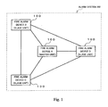
- FIG. 1 is a diagram illustrating a configuration of an alarm system 200 according to the embodiment of the present invention.
- the alarm system 200 includes a plurality of fire alarm devices 100.
- Each of the plurality of fire alarm devices 100 has a function of detecting a fire, and also has a function of issuing an alarm independently.
- all the fire alarm devices 100 have the same configuration, and are capable of operating as both a master unit and a slave unit depending on setting of an operation setting section. It should be noted that, in order to distinguish the fire alarm devices 100 from one another, the fire alarm devices 100 may be referred to as a fire alarm device A, a fire alarm device B, a fire alarm device C, and a fire alarm device D, respectively. Here, the fire alarm devices A to D belong to the same one group. Further, in FIG. 1 , solid lines connecting the fire alarm devices 100 show that the fire alarm devices 100 are capable of communicating with each other through wireless communication.
- FIG 2 is a functional block diagram illustrating a main configuration of the fire alarm device 100 according to the embodiment of the present invention.
- the fire alarm device 100 includes a control circuit 1, a battery 2, a power supply circuit 3, a battery voltage detection circuit 4, a transmitting/receiving circuit 5, an antenna 6, a fire detection circuit 7, an alarm sound control circuit 8, and an indicator lamp circuit 9.
- the battery 2 supplies DC power to the power supply circuit 3.
- the power supply circuit 3 controls the voltage of the battery 2 to a predetermined voltage, and then supplies the predetermined voltage to the control circuit 1, the transmitting/receiving circuit 5, the fire detection circuit 7, the alarm sound control circuit 8, and the indicator lamp circuit 9.
- the battery voltage detection circuit 4 detects the voltage of the battery 2 which is applied to the power supply circuit 3, and then outputs, to the control circuit 1, a battery voltage detection signal corresponding to the detected voltage. When it is detected that the level of the battery 2 has declined or fallen below a threshold for battery exhaustion, the battery voltage detection circuit 4 activates the alarm sound control circuit 8 and the indicator lamp circuit 9, and also causes the transmitting/receiving circuit 5 to output a status signal containing battery exhaustion status information under the control of the control circuit 1.
- the fire detection circuit 7 corresponds to a status detection section of the present invention.
- the fire detection circuit 7 detects a physical quantity or physical change of a detection subject, such as smoke or heat, which is generated by a fire phenomenon, and then outputs a signal corresponding to a detection content to the control circuit 1.
- the alarm sound control circuit 8 is a circuit for controlling an operation of sounding an alarm, which is performed by a buzzer, a speaker, or the like.
- the indicator lamp circuit 9 is a circuit for controlling an operation of turning on an indicator lamp such as an LED.
- the transmitting/receiving circuit 5 is connected to the antenna 6 for transmitting and receiving radio signals.
- the transmitting/receiving circuit 5 processes a radio signal input via the antenna 6. Then, when the signal is directed to its own device, the transmitting/receiving circuit 5 performs reception processing. On the other hand, when the signal is not directed to its own device, the transmitting/receiving circuit 5 does not perform the reception processing.
- the signal subjected to the reception processing is output to the control circuit 1. Further, the transmitting/receiving circuit 5 is controlled by the control circuit 1, and performs transmission processing for a signal such as the status signal.
- the control circuit 1 Based on a signal output by the fire detection circuit 7, the control circuit 1 controls the alarm sound control circuit 8 and the indicator lamp circuit 9, to thereby issue an alarm by means of the sound and the indicator lamp and stop the alarm. Further, while performing necessary processing based on a signal received by the transmitting/receiving circuit 5, the control circuit 1 controls the transmitting/receiving circuit 5 if necessary, to thereby transmit a signal such as the status signal to another fire alarm device. It should be noted that a status judgment section of the present invention corresponds to the control circuit 1 in this embodiment.
- control circuit 1 includes an operation setting section 11.
- the operation setting section 11 has a function of performing setting as to whether the fire alarm device 100 is to operate as the master unit or the slave unit.
- control circuit 1 controls operation of each component based on a program stored in a storage section 10 described below so that the fire alarm device 100 operates as the master unit or the slave unit.
- the storage section 10 contains a master unit operation program 101, which is a control program used in the case where the fire alarm device 100 is to operate as the master unit, and a slave unit operation program 102, which is a control program used in the case where the fire alarm device 100 is to operate as the slave unit.
- the control circuit 1 performs operation control based on the master unit operation program 101 or the slave unit operation program 102.
- the fire alarm device 100 is capable of operating as both the master unit and the slave unit.
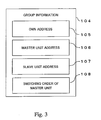
- the storage section 10 contains a battery voltage threshold 103 and group information 104.
- the battery voltage threshold 103 As the battery voltage threshold 103, a threshold for making judgment on the battery voltage detected by the battery voltage detection circuit 4 is stored. It should be noted that switching availability judgment information of the present invention corresponds to the battery voltage threshold 103 in this embodiment.
- group information 104 various kinds of information regarding an own device and a group to which the own device belongs are stored.
- the group information 104 contains an own address 105, a master unit address 106, a slave unit address 107, and a switching order of master unit 108. Further, the group information 104 also contains a group ID (not shown) for identifying a group.
- the own address 105 is address information uniquely given to each of the fire alarm devices 100 of the alarm system 200.
- the description is given by referring to the addresses of the fire alarm devices A to D as, for example, addresses A to D, respectively.
- the master unit address 106 corresponds to the own address 105 of the fire alarm device 100 operating as the master unit in the alarm system 200.
- all the fire alarm devices 100 store, as the master unit address 106, the address A corresponding to the own address 105 of the fire alarm device A.
- the slave unit address 107 corresponds to the own address 105 of each of the other fire alarm devices 100 excluding the own device among the fire alarm devices 100 operating as the slave unit in the alarm system 200.
- the fire alarm device B stores, as the slave unit address 107, the address C and the address D excluding the address B.
- the switching order of master unit 108 is information indicating an order of the fire alarm devices A to D which is used in switching the master unit.
- the switching order of master unit 108 may be determined arbitrarily. For example, the order in which the fire alarm devices 100 are added to the alarm system 200 may be set as the switching order of master unit 108.
- master unit address 106 the slave unit address 107, and the switching order of master unit 108 are rewritable.
- a plurality of the fire alarm devices 100 thus configured constitute one group, in which one device operates as the master unit and the other devices operate as the slave unit.
- Setting as the master unit is performed by, for example, depressing a registration button (switch, not shown) after power-on.
- setting as the slave unit is performed by, for example, depressing the registration button (switch, not shown) of the master unit to enter into a registration mode, and depressing the registration button (switch, not shown) after the power-on of the slave unit.
- the fire alarm device 100 performs wireless communication to store the group information 104, and also uses the operation setting section 11 to perform the setting.
- the fire alarm device A detects a fire with the fire detection circuit 7 to issue an alarm by means of the sound or the indicator lamp, and also transmits, as a interlock signal, information regarding the fire to the other slave units (fire alarm devices B to D). Then, the slave units (fire alarm devices B to D) that have received the interlock signal transmitted by the master unit (fire alarm device A) issue a necessary alarm by means of the sound or the indicator lamp. After that, if the master unit (fire alarm device A) has ceased detecting the fire, the master unit carries out self-restoration to stop the alarm, and also stops transmitting the interlock signal to the other slave units (fire alarm devices B to D). Then, the other slave units (fire alarm devices B to D), which no longer receive the interlock signal, stop the alarm as well.
- the fire alarm device B detects a fire with the fire detection circuit 7 to issue an alarm by means of the sound or the indicator lamp, and also transmits, as a interlock signal, information regarding the fire to the master unit (fire alarm device A) and the other slave units (fire alarm devices C and D). Then, the master unit (fire alarm device A) and the other slave units (fire alarm devices C and D) that have received the interlock signal transmitted by the fire alarm device B issue a necessary alarm by means of the sound or the indicator lamp.
- the master unit which has received the interlock signal issued by the fire alarm device B serving as the slave unit, transfers the interlock signal to other slave units (fire alarm devices C and D) than the fire alarm device B serving as a transmission source.
- the slave units fire alarm devices B to D
- the fire alarm devices C and D can receive the interlock signal transferred by the master unit (fire alarm device A).
- the fire alarm device B After that, if the fire alarm device B has ceased detecting the fire, the fire alarm device B carries out self-restoration to stop the alarm, and also stops transmitting the interlock signal to the master unit (fire alarm device A) and the other slave units (fire alarm devices C and D). Then, the master unit (fire alarm device A) and the slave units (fire alarm devices C and D), which no longer receive the interlock signal, stop the alarm as well. In this manner, the master unit (fire alarm device A) and the slave units (fire alarm devices B to D) perform an alarm operation in synchronization with one another, and hence it is possible to deliver the alarm to a user more reliably.
- the master unit in order to check the status of each of the fire alarm devices 100, periodical transmission for status check is performed during fire monitoring (normal status).
- the master unit at a predetermined transmission timing, the master unit (fire alarm device A) transmits a status signal to the slave units (fire alarm devices B to D).
- the status signal contains status information on the master unit (fire alarm device A) or on a group to which the master unit belongs, and information containing the own address 105 for identifying the transmission source.
- This status signal may be repeatedly transmitted a predetermined number of times. With this configuration, a probability of normal reception by the slave units (fire alarm devices B to D) can be increased.
- the slave units When the slave units (fire alarm devices B to D) have received the status signal from the master unit (fire alarm device A), for example, the slave units transmit, as the status signal, the status information regarding the own device and information containing the own address 105 for identifying the transmission source, to the master unit (fire alarm device A).
- the master unit (fire alarm device A) and the slave units (fire alarm devices B to D) use the own addresses 105 contained in the respective status signals to make a distinction as to which fire alarm device has transmitted the signal.
- the status information regarding the master unit and the slave units (fire alarm devices A to D) there are enumerated the battery level, a sensor status (degradation, contamination, etc.) of the fire detection circuit 7, and the number of times the reception processing has been performed (number of times processing for irregular radio has been performed).
- the status information regarding the group there are enumerated an address or a group ID of a slave unit that is suffering an abnormality, and an address or a group ID of a slave unit for which wireless communication is not established.
- the fire alarm device 100 operating as the master unit is switched when a predetermined period of time has elapsed.
- a current master unit selects a slave unit that is to become a next master unit according to the order stored as the switching order of master unit 108, and then transmits, to all the slave units, information regarding the current master unit and information regarding the slave unit that is to become the next master unit.
- the slave unit that is to become the next master unit judges whether or not the switching of the master unit is possible based on the switching availability judgment information, and transmits, as a response, a result of the judgment to the master unit and the other slave units.
- the slave unit that is to become the next master unit performs the switching. If the switching is impossible, the slave unit that is to become the next master unit transmits an abnormality signal to the current master unit and the other slave units. It should be noted that in a case where the switching of the master unit has failed, the current master unit makes an attempt to switch the master unit again with respect to another slave unit according to the switching order of master unit 108. In this manner, the switching of the master unit is performed at predetermined time intervals.
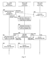
- FIGS. 4 to 6 are diagrams each illustrating a flow of an operation performed when the master unit is switched from the master unit (fire alarm device A) to the slave unit (fire alarm device B).
- FIG. 4 is a diagram illustrating a case where the switching of the master unit from the master unit (fire alarm device A) to the slave unit (fire alarm device B) is performed normally.
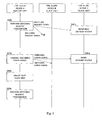
- FIGS. 5 and 6 are diagrams each illustrating a case where the switching of the master unit from the master unit (fire alarm device A) to the slave unit (fire alarm device B) fails.
- FIGS. 4 to 6 illustrate only the fire alarm device C.
- description is given by taking as an example a case where the switching order of master unit 108 is set in order of the fire alarm device A, the fire alarm device B, the fire alarm device C, and the fire alarm device D.
- the master unit transmits a request signal for switching the master unit to all the slave units (fire alarm devices B to D) belonging to the same group (alarm system 200).
- the switching request signal contains the address A, which is the own address 105 of the master unit (fire alarm device A), and the address B, which is the own address 105 of the fire alarm device B, as the information on the current master unit and the information on the next master unit, respectively.
- switching request transmission is performed at a predetermined master unit switching timing.
- the master unit switching timing an arbitrary periodical timing may be set, such as every predetermined time interval or at predetermined time points. The transmission timing determined for the operation of the above-mentioned periodical transmission and the master unit switching timing may be made coincide with each other.
- the slave unit (fire alarm device B) which is to become the master unit next and has the address B set as the own address 105 receives the request signal for switching the master unit, and then judges whether or not the switching of the master unit is possible. In the judgment, it is checked whether or not the battery voltage detected by the battery voltage detection circuit 4 is larger than the battery voltage threshold 103 stored in the storage section 10. When the battery voltage is larger than the battery voltage threshold 103, it is judged that the switching of the master unit is possible. On the other hand, when the battery voltage is equal to or smaller than the battery voltage threshold 103, it is judged that the switching of the master unit is impossible. It should be noted that, as the battery voltage threshold 103, there is set a value indicating a battery level high enough for the fire alarm device 100 to operate as the master unit until the next master unit switching timing.
- the fire alarm device B performs operation setting as the master unit. Specifically, the operation setting section 11 performs setting so that the fire alarm device B operates as the master unit, and the control circuit 1 starts the operation control according to the master unit operation program 101.
- the fire alarm device B transmits, as response transmission, a response signal in response to the switching request transmission, to the fire alarm device A and the other slave units (fire alarm devices C and D).
- the response signal contains a signal indicating that the switching of the master unit has been completed. Because the fire alarm device B has the master unit address 106 and the slave unit addresses 107 stored as the group information 104, the fire alarm device B can transmit the response signal to all the fire alarm devices 100 within the group.
- the fire alarm device B updates the group information 104.
- the fire alarm device B stores the address B as the master unit address 106, and also stores the address A, the address C, and the address D as the slave unit addresses 107.
- the address A of the fire alarm device A which has been the master unit before the switching, is additionally stored as the slave unit address 107.
- the fire alarm device A When the fire alarm device A has received the response signal indicating that the switching of the master unit has been completed, the fire alarm device A performs operation setting as the slave unit. Specifically, the operation setting section 11 performs setting so that the fire alarm device A operates as the slave unit, and the control circuit 1 starts the operation control according to the slave unit operation program 102.
- the fire alarm device A updates the group information 104.
- the fire alarm device A stores the address of the fire alarm device B as the master unit address 106, and also stores the addresses of the fire alarm device C and the fire alarm device D as the slave unit addresses 107.
- the address B of the fire alarm device B which is the master unit after the switching, is deleted from the slave unit addresses 107.
- the slave unit which does not have the address B for the next master unit set as the own address 105 receives the switching request signal transmitted by the fire alarm device A to recognize that the switching of the master unit is performed from the fire alarm device A to the fire alarm device B, and enters into a standby status for reception of a signal regarding the switching of the master unit.
- the fire alarm device C updates the group information 104.
- the fire alarm device C sets the address B as the master unit address 106, and also additionally stores the address A as the slave unit address 107.
- the fire alarm device C stores the address A and the address D as the slave unit addresses 107.
- the master unit (fire alarm device A) transmits a request signal for switching the master unit to all the slave units (fire alarm devices B to D). This processing is the same as that of Step S20 described above with reference to FIG 4 .
- the slave unit which is to become the master unit next and has the address B set as the own address 105 judges whether or not the switching of the master unit is possible. Assume that the battery voltage detected by the battery voltage detection circuit 4 is equal to or smaller than the battery voltage threshold 103 stored in the storage section 10, and hence it is judged that the switching of the master unit is impossible.
- the fire alarm device B transmits a response signal in response to the switching request transmission, to the fire alarm device A and the other slave units (fire alarm devices C and D).
- the response signal contains a signal indicating that the switching of the master unit from the fire alarm device A to the fire alarm device B has failed.
- the fire alarm device A When the fire alarm device A has received the response signal indicating that the switching of the master unit has failed, the fire alarm device A refers to the switching order of master unit 108, to thereby select a fire alarm device (in this example, fire alarm device C) that is to become the master unit next instead of the fire alarm device B.
- a fire alarm device in this example, fire alarm device C
- the fire alarm device A attempts to switch the master unit by performing the switching request transmission that specifies the fire alarm device C as the next master unit (containing the address A of the current master unit and the address C of the next master unit).
- the subsequent processing is the same as described above.
- the slave unit which does not have the address B for the next master unit set as the own address 105 receives the switching request signal transmitted by the fire alarm device A to recognize that the switching of the master unit is performed from the fire alarm device A to the fire alarm device B, and then enters into the standby status for reception of a signal regarding the switching of the master unit.
- the fire alarm device C when the fire alarm device C has received the response signal indicating that the switching of the master unit has failed, the fire alarm device C resets the standby status, and returns to a status of before the reception of the switching request signal.
- FIG. 6 description is given of another operation performed when the switching of the master unit fails.
- the master unit (fire alarm device A) transmits a request signal for switching the master unit to all the slave units (fire alarm devices B to D).
- This processing is the same as that of Step S20 described above with reference to FIG. 4 .
- the fire alarm device B Because the fire alarm device B which is to become the next master unit and has the address B set as the own address 105 has not received the switching request signal, the fire alarm device B continues a normal monitoring status, and does not perform the processing of judging whether or not the switching of the master unit is possible.
- the fire alarm device A judges that the switching of the master unit has failed, and then transmits a switching error signal to all the slave units.
- the fire alarm device A refers to the switching order of master unit 108, to thereby identify a fire alarm device (in this example, fire alarm device C) that is to become the master unit next instead of the fire alarm device B.
- a fire alarm device in this example, fire alarm device C
- the fire alarm device A performs the switching request transmission that specifies the fire alarm device C as the next master unit.
- the subsequent processing is the same as described above.
- the slave unit which does not have the address B for the next master unit set as the own address 105 receives the switching request signal transmitted by the fire alarm device A to recognize that the switching of the master unit is performed from the fire alarm device A to the fire alarm device B, and then enters into the standby status for reception of a signal regarding the switching of the master unit.
- the fire alarm device C resets the standby status, and returns to a status of before the reception of the switching request signal.
- each of the fire alarm devices 100 stores that slave unit as a "switching impossible" slave unit in the switching order of master unit 108, and the switching of the master unit is not performed with respect to the fire alarm device B. Then, if the switching of the master unit has become possible due to replacement of the battery or the like, the fire alarm device B is added to the switching order of master unit 108.
- the fire alarm device 100 switches the master unit at the predetermined timing.
- the master unit manages terminal information within the alarm system and relays signals
- the master unit has larger current consumption than the slave unit.
- the master unit by switching the master unit in turn, it can be avoided that the battery life of a particular fire alarm device 100 becomes shorter, which prevents unbalanced battery lives.
- the master unit requires more frequent replacement of the battery than the other slave units. Because no master unit exists during the replacement of the battery, the alarm system 200 cannot operate as a system, making impossible an alarm synchronization operation.
- the fire alarm device 100 and the alarm system 200 it is possible to prevent the alarm system 200 from suffering a system failure caused by a lowered battery level of the master unit, which enables the alarm system 200 to enhance a fail-safe function.
- the master unit is switched at the periodical timing, such as every predetermined time interval or at predetermined time points. Therefore, time lengths in which the respective fire alarm devices 100 operate as the master unit are made uniform, which enables preventing unbalanced battery lives among the fire alarm devices 100.
- the fire alarm device 100 is capable of operating as both the master unit and the slave unit. Therefore, there is no need to manufacture fire alarm devices that have different specifications depending on whether the device is the master unit or the slave unit. As a result, by sharing the manufacturing process and the inspection process, manufacturing cost can be suppressed.
- the description has been given by taking as an example the case where the switching of the master unit is performed at the periodical timing, but the present invention may be combined with another configuration so that the switching of the master unit is performed at another timing.
- the switching of the master unit may be performed. By doing so, it becomes possible to prevent the alarm system 200 from suffering a system failure caused by a lowered battery level of the master unit.
- the electric field intensity of radio waves may be measured to use a value of the electric field intensity as the switching availability judgment information.
- the electric field intensity and the battery level may be used in combination.
- the description has been given by taking as an example the case where the switching order of master unit 108 is set arbitrarily in advance, but the order may be changed dynamically.
- the master unit may acquire the values of the battery levels from the slave units in advance, to thereby set a fire alarm device having a higher battery level as the next master unit. With this configuration, it is possible to prevent the fire alarm devices from having unbalanced battery levels thereamong.
- the description has been given by taking as an example the case where the present invention is applied to the alarm system including the fire alarm devices that are powered by the battery and perform wireless communication, but the present invention does not limit a power supply method or a communication method of the fire alarm device. Further, apart from the fire alarm device, the present invention is also applicable to an alarm device for abnormality detection or the like.
Applications Claiming Priority (1)
| Application Number | Priority Date | Filing Date | Title |
|---|---|---|---|
| JP2008310650A JP5213672B2 (ja) | 2008-12-05 | 2008-12-05 | 警報システム及び警報器 |
Publications (2)
| Publication Number | Publication Date |
|---|---|
| EP2199997A2 true EP2199997A2 (de) | 2010-06-23 |
| EP2199997A3 EP2199997A3 (de) | 2010-12-22 |
Family
ID=41716168
Family Applications (1)
| Application Number | Title | Priority Date | Filing Date |
|---|---|---|---|
| EP09252735A Ceased EP2199997A3 (de) | 2008-12-05 | 2009-12-04 | Alarmsystem und Alarmvorrichtung |
Country Status (6)
| Country | Link |
|---|---|
| US (1) | US8269642B2 (de) |
| EP (1) | EP2199997A3 (de) |
| JP (1) | JP5213672B2 (de) |
| KR (1) | KR20100065090A (de) |
| CN (1) | CN101819709B (de) |
| TW (1) | TWI462059B (de) |
Cited By (3)
| Publication number | Priority date | Publication date | Assignee | Title |
|---|---|---|---|---|
| ITTO20120498A1 (it) * | 2012-06-07 | 2013-12-08 | Marco Bersano | Sistema di allarme per un'area da monitorare, in particolare una zona commerciale o industriale, quale un cantiere. |
| EP2897395A4 (de) * | 2012-09-11 | 2015-10-14 | Panasonic Ip Man Co Ltd | Drahtloses kommunikationssystem |
| EP2897396A4 (de) * | 2012-09-11 | 2015-11-11 | Panasonic Ip Man Co Ltd | Drahtloses kommunikationssystem |
Families Citing this family (11)
| Publication number | Priority date | Publication date | Assignee | Title |
|---|---|---|---|---|
| JP5879784B2 (ja) * | 2011-07-11 | 2016-03-08 | 富士通株式会社 | 携帯端末、携帯端末制御方法および携帯端末制御プログラム |
| US8723672B2 (en) * | 2011-11-11 | 2014-05-13 | Microchip Technology Incorporated | Automatic audible alarm origination locate |
| US9202359B2 (en) * | 2012-08-30 | 2015-12-01 | Honeywell International Inc. | Multilevel signaling system and method |
| US9875644B2 (en) | 2014-09-09 | 2018-01-23 | Tyco Fire & Security Gmbh | Master slave wireless fire alarm and mass notification system |
| CN107016839B (zh) * | 2016-01-28 | 2019-02-15 | 陕西飞机工业(集团)有限公司 | 一种飞机火警控制盒综合试验器 |
| US10163312B2 (en) | 2016-09-30 | 2018-12-25 | Western Digital Technologies, Inc. | Autonomously operating light emitting devices providing detection and warning of hazardous condition on path of travel |
| JP7082895B2 (ja) * | 2018-03-30 | 2022-06-09 | ニッタン株式会社 | 無線式警報器およびそれを用いた警報システム |
| TWI705422B (zh) * | 2019-02-18 | 2020-09-21 | 巨輪興業股份有限公司 | 協調方法及其警示裝置 |
| TWI750565B (zh) * | 2020-01-15 | 2021-12-21 | 原相科技股份有限公司 | 真無線多聲道揚聲裝置及其多音源發聲之方法 |
| CN112511335B (zh) * | 2020-11-02 | 2022-03-25 | 珠海格力电器股份有限公司 | It设备的控制方法、装置和一种数据中心管理系统 |
| BE1029472B1 (nl) * | 2021-06-08 | 2023-01-16 | Unmatched Bv | Werkwijze voor opvolgen en afhandelen van alarmen in een alarmeringssysteem en een alarmeringssysteem |
Citations (2)
| Publication number | Priority date | Publication date | Assignee | Title |
|---|---|---|---|---|
| US6901275B1 (en) * | 1999-09-30 | 2005-05-31 | Kabushiki Kaisha Toshiba | Communication system, and communication device and communication method for use in the communication system |
| JP2005294943A (ja) | 2004-03-31 | 2005-10-20 | Ricoh Elemex Corp | 無線子機、無線親機、及び特定小電力無線双方向通信システム |
Family Cites Families (12)
| Publication number | Priority date | Publication date | Assignee | Title |
|---|---|---|---|---|
| US4531114A (en) * | 1982-05-06 | 1985-07-23 | Safety Intelligence Systems | Intelligent fire safety system |
| JPH0749988A (ja) * | 1993-06-15 | 1995-02-21 | Hochiki Corp | 無線式警報装置 |
| JP2924828B2 (ja) * | 1996-11-07 | 1999-07-26 | 日本電気株式会社 | アドホックネットワークシステムとその接続方法 |
| US6028513A (en) * | 1998-02-27 | 2000-02-22 | Pittway Corporation | Wireless activation of multiple alarm devices upon triggering of a single device |
| US6144310A (en) * | 1999-01-26 | 2000-11-07 | Morris; Gary Jay | Environmental condition detector with audible alarm and voice identifier |
| DE19930423A1 (de) * | 1999-07-01 | 2001-01-18 | Siemens Ag | Schnurloses Datenübertragungsnetzwerk und Verfahren zu seiner Verwaltung |
| US6614347B2 (en) * | 2001-01-30 | 2003-09-02 | Ranco Inc. | Apparatus and method for providing alarm synchronization among multiple alarm devices |
| EP1324540B1 (de) * | 2001-12-28 | 2011-08-17 | Fujitsu Toshiba Mobile Communications Limited | Funkkommunikationsgerät |
| JP3933502B2 (ja) * | 2002-03-15 | 2007-06-20 | 株式会社東芝 | 無線通信装置 |
| KR20060017576A (ko) * | 2003-06-02 | 2006-02-24 | 마쯔시다덴기산교 가부시키가이샤 | 마스터/슬래이브 스위칭 프로세스를 수행하는 디바이스, 방법, 및 프로그램 |
| ES2521668T3 (es) * | 2007-01-17 | 2014-11-13 | Panasonic Corporation | Sistema inalámbrico de alarma de incendio |
| EP2256707A4 (de) * | 2008-03-17 | 2016-03-02 | Hochiki Co | Alarm |
-
2008
- 2008-12-05 JP JP2008310650A patent/JP5213672B2/ja active Active
-
2009
- 2009-11-10 TW TW098138090A patent/TWI462059B/zh not_active IP Right Cessation
- 2009-11-11 KR KR1020090108507A patent/KR20100065090A/ko not_active Application Discontinuation
- 2009-11-18 CN CN200910223374.9A patent/CN101819709B/zh not_active Expired - Fee Related
- 2009-12-02 US US12/629,276 patent/US8269642B2/en not_active Expired - Fee Related
- 2009-12-04 EP EP09252735A patent/EP2199997A3/de not_active Ceased
Patent Citations (2)
| Publication number | Priority date | Publication date | Assignee | Title |
|---|---|---|---|---|
| US6901275B1 (en) * | 1999-09-30 | 2005-05-31 | Kabushiki Kaisha Toshiba | Communication system, and communication device and communication method for use in the communication system |
| JP2005294943A (ja) | 2004-03-31 | 2005-10-20 | Ricoh Elemex Corp | 無線子機、無線親機、及び特定小電力無線双方向通信システム |
Cited By (4)
| Publication number | Priority date | Publication date | Assignee | Title |
|---|---|---|---|---|
| ITTO20120498A1 (it) * | 2012-06-07 | 2013-12-08 | Marco Bersano | Sistema di allarme per un'area da monitorare, in particolare una zona commerciale o industriale, quale un cantiere. |
| EP2672471A1 (de) * | 2012-06-07 | 2013-12-11 | Marco Bersano | Alarmsystem für eine zu überwachende Fläche, insbesondere für Gewerbe- und Industrieflächen wie eine Baustelle |
| EP2897395A4 (de) * | 2012-09-11 | 2015-10-14 | Panasonic Ip Man Co Ltd | Drahtloses kommunikationssystem |
| EP2897396A4 (de) * | 2012-09-11 | 2015-11-11 | Panasonic Ip Man Co Ltd | Drahtloses kommunikationssystem |
Also Published As
| Publication number | Publication date |
|---|---|
| US20100141461A1 (en) | 2010-06-10 |
| EP2199997A3 (de) | 2010-12-22 |
| CN101819709B (zh) | 2014-04-02 |
| US8269642B2 (en) | 2012-09-18 |
| KR20100065090A (ko) | 2010-06-15 |
| JP2010134737A (ja) | 2010-06-17 |
| CN101819709A (zh) | 2010-09-01 |
| TW201032185A (en) | 2010-09-01 |
| JP5213672B2 (ja) | 2013-06-19 |
| TWI462059B (zh) | 2014-11-21 |
Similar Documents
| Publication | Publication Date | Title |
|---|---|---|
| EP2199997A2 (de) | Alarmsystem und Alarmvorrichtung | |
| EP2194514A1 (de) | Optimierung der Datenübertragung zwischen Alarmvorrichtungen | |
| JP6561132B2 (ja) | 燃料電池装置、燃料電池システム、燃料電池システムの制御方法、及びコントローラ | |
| CN107819617B (zh) | 一种通信设备的监控方法和通信设备 | |
| JP2010134623A (ja) | 警報システム | |
| JP2000031875A (ja) | 通信端末装置および通信制御装置ならびにデータ通信システム | |
| JP5171581B2 (ja) | 警報器 | |
| JP2011209837A (ja) | 無線式警報システム | |
| JP6430802B2 (ja) | 無線防災システム | |
| JP6622373B2 (ja) | 無線防災システム及び無線防災システムのid設定方法 | |
| JP5320327B2 (ja) | 通信システム | |
| CN113169907B (zh) | 通信装置及控制方法 | |
| JP5312381B2 (ja) | 警報器及び警報システム | |
| JP5723645B2 (ja) | 移報出力器 | |
| JP2016149029A (ja) | 自動火災報知システムの子機、親機、およびそれを用いた自動火災報知システム | |
| JP4348161B2 (ja) | 火災受信機 | |
| JP2010049622A (ja) | ワイヤレス警報システム | |
| JP2011209799A (ja) | 無線式警報システム | |
| JP2003248887A (ja) | ポーリング式火災検出方法及び導通確認方法並びに多重伝送式火災受信機 | |
| JP2007086851A (ja) | 伝送システム、その受信盤およびその端末 | |
| JP2016053992A (ja) | 無線通信システム | |
| JP2001325117A (ja) | 待機2重系情報処理装置およびその系状態確定方法 | |
| JP5665629B2 (ja) | 警報システム | |
| JP2012088957A (ja) | 警報システム | |
| JP2005266950A (ja) | 火災感知器 |
Legal Events
| Date | Code | Title | Description |
|---|---|---|---|
| PUAI | Public reference made under article 153(3) epc to a published international application that has entered the european phase |
Free format text: ORIGINAL CODE: 0009012 |
|
| AK | Designated contracting states |
Kind code of ref document: A2 Designated state(s): AT BE BG CH CY CZ DE DK EE ES FI FR GB GR HR HU IE IS IT LI LT LU LV MC MK MT NL NO PL PT RO SE SI SK SM TR |
|
| AX | Request for extension of the european patent |
Extension state: AL BA RS |
|
| PUAL | Search report despatched |
Free format text: ORIGINAL CODE: 0009013 |
|
| AK | Designated contracting states |
Kind code of ref document: A3 Designated state(s): AT BE BG CH CY CZ DE DK EE ES FI FR GB GR HR HU IE IS IT LI LT LU LV MC MK MT NL NO PL PT RO SE SI SK SM TR |
|
| AX | Request for extension of the european patent |
Extension state: AL BA RS |
|
| 17P | Request for examination filed |
Effective date: 20110622 |
|
| 17Q | First examination report despatched |
Effective date: 20111012 |
|
| STAA | Information on the status of an ep patent application or granted ep patent |
Free format text: STATUS: THE APPLICATION HAS BEEN REFUSED |
|
| 18R | Application refused |
Effective date: 20140403 |