EP2199740A2 - Vorrichtung zur Erfassung der Winkelgeschwindigkeit - Google Patents
Vorrichtung zur Erfassung der Winkelgeschwindigkeit Download PDFInfo
- Publication number
- EP2199740A2 EP2199740A2 EP09177080A EP09177080A EP2199740A2 EP 2199740 A2 EP2199740 A2 EP 2199740A2 EP 09177080 A EP09177080 A EP 09177080A EP 09177080 A EP09177080 A EP 09177080A EP 2199740 A2 EP2199740 A2 EP 2199740A2
- Authority
- EP
- European Patent Office
- Prior art keywords
- angular velocity
- vibrating body
- displacement
- signal
- vibration
- Prior art date
- Legal status (The legal status is an assumption and is not a legal conclusion. Google has not performed a legal analysis and makes no representation as to the accuracy of the status listed.)
- Withdrawn
Links
Images


Classifications
-
- G—PHYSICS
- G01—MEASURING; TESTING
- G01C—MEASURING DISTANCES, LEVELS OR BEARINGS; SURVEYING; NAVIGATION; GYROSCOPIC INSTRUMENTS; PHOTOGRAMMETRY OR VIDEOGRAMMETRY
- G01C19/00—Gyroscopes; Turn-sensitive devices using vibrating masses; Turn-sensitive devices without moving masses; Measuring angular rate using gyroscopic effects
- G01C19/56—Turn-sensitive devices using vibrating masses, e.g. vibratory angular rate sensors based on Coriolis forces
Definitions
- the present invention is related to a vibration type angular velocity sensor and pertains in particular to an angular velocity sensor that reduces the influence of phase variations in the displacement signal of a vibrating body.
- the technology reported in Japanese Patent No. 3,603,501 provides a compensating vibration generating means making a vibrating body make compensating vibrations in the direction of the detection axis and suppresses leakage vibrations generated in the direction of the detection axis when no angular velocity is applied to the vibrating body. Consequently, there is a need to provide a compensating vibration generating means inside the angular velocity detection element and a compensation drive circuit in the control part.
- the present invention is made to take circumstances such as these into account, implements a plurality of control functions with time division by means of one circuit, and, in addition, implements the aforementioned functions by means of one CPU or DSP and software.
- the angular velocity detecting apparatus (hereinafter called “angular velocity sensor”) according to an embodiment of the present invention comprises:
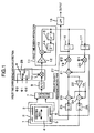
- Fig. 1 is a block diagram of the control circuits of an angular velocity sensor of Embodiment 1.
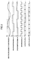
- Fig. 2 is a timing chart of the control circuit of an angular velocity sensor of Embodiment 1.
- a detection element 1 of the angular velocity sensor of the present embodiment includes:
- the signal processing part includes: a capacitive detector 7 detecting the displacement due to the Coriolis force on vibrating body 4 by detecting the difference between the capacitance between vibrating body 4 and fixed electrode 3 and the capacitance between vibrating body 4 and fixed electrode 6; an A/D converter 8 converting the output of capacitive detector 7 into a digital signal; a 2-slot time division synchronous detection part 28 which has: a switch 9 switching, with a signal ⁇ 3 having a frequency which is four times greater than drive frequency fd, between two signals having a frequency of drive frequency fd as shown in Fig.
- a 2-slot time division integration part 11 having a coefficient multiplier 12 determining the integration gain, an adder 13 carrying out integral calculations, and a shift register including delay circuits 14 and 15 and having a delay in time that is the inverse number of eight times the frequency of vibration frequency fd; a latch circuit 16 holding the output of adder 13 at times during which the state of switching signal ⁇ 3 is "1"; a latch circuit 17 holding the output of adder 13 at times during which the state of switching signal ⁇ 3 is "0"; an LPF (Low Pass Filter) 18 extracting the DC component of the output of latch circuit 16; and an angular velocity vibration control unit 27 which has:
- the displacement of vibrating body 4 due to the Coriolis force acting on vibrating body 4 is detected by means of fixed electrodes 3 and 6 and capacitive detector 7. And then, there is carried out the action of negating the leakage vibration from the vibration axis direction, resulting from the Coriolis force acting on vibrating body 4 and structural warps and the like of the vibrating body, by impressing a voltage on fixed electrodes 2 and 5 by means of the electrostatic force generated between the fixed electrodes and the vibrating body.
- a part of the feedback voltage during servo control is considered to be an angular velocity detection signal and is output.
- synchronous detection with respect to the displacement signal of the vibrating body obtained via capacitive detector 7 and A/D converter 8, is carried out with 2-slot time division synchronous detection part 28 by means of synchronization signal ⁇ 1 shown in Fig. 2 and the vibration displacement (hereinafter called the Coriolis component) in the direction perpendicular to the axis of vibration.
- Fig. 3 is a block diagram of the signal processing circuits of an angular velocity sensor of Embodiment 2.
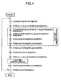
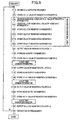
- Fig. 4 is a flowchart of the control program of the angular velocity sensor of Embodiment 2.
- the present embodiment is one indicating a configuration, in Embodiment 1 of Fig. 1 , in which 2-slot time division synchronous detection part 28 and 2-slot time division integration part 11 are implemented by means of a Digital Signal Processor (DSP) and a control program therefor.
- DSP part 30 includes:
- the cycle interval from the command code of Step 1 to that of Step 11 is 1/fd and the 2-slot time division integration process executed during a cycle in Steps 3 to 6 is executed twice, for the Coriolis component and the error component. According to the aforementioned processing, processing equivalent to that of Embodiment 1 is implemented.
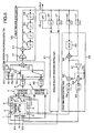
- Fig. 5 is a block diagram of the signal processing circuits of an angular velocity sensor of Embodiment 3.
- Fig. 6 is a timing chart of the signal processing circuit of the angular velocity sensor of Embodiment 3.
- the present embodiment is a configuration in which a drive axis direction vibration control function has been added to Embodiment 1 of Fig. 1 .
- detection element 1 fixed electrodes 61 and 62 are electrodes (displacement detection parts) detecting the vibration amplitude and vibration frequency of vibrating body 4 with changes in the capacitance.
- fixed electrodes 63 and 64 are electrodes (external force application parts) making an electrostatic force operate in order to regulate the vibration amplitude and vibration frequency of vibrating body 4.
- the signal processing circuit shown in Fig. 5 includes:
- an AC voltage is impressed on fixed electrodes 63 and 64 in order to make vibrating body 4 vibrate in the vibration axis direction and the displacement (amplitude and frequency) in the vibration axis direction of vibrating body 4 due thereto is detected by means of fixed electrodes 61 and 62 and capacitive detector 41. And then, due to the electrostatic force generated by means of the voltage impressed on fixed electrodes 63 and 64, servo control is carried out so as to feed back to the sensor a voltage devised so that the vibration amplitude and vibration frequency, in the direction of the axis of vibration, of vibrating body 4 have designated values.
- the displacement of vibrating body 4 due to the Coriolis force is detected by means of fixed electrodes 3 and 6 and capacitive detector 7. And then, by means of the electrostatic force generated by the voltage impressed on fixed electrodes 2 and 5, servo control of the impressed voltage is carried out in order to set the displacement of vibrating body 4 due to the Coriolis force and leakage vibration arising in a direction perpendicular to the axis of vibration to zero. And then, a part of the feedback voltage at that time is considered to be the angular velocity detection signal and extracted.
- each integral calculation result being the output of adder 13 is stored and shifted in the shift register composed of delay circuits 14, 15, 44, and 45.
- the outputs of 4-slot time division integration part 56 are stored in latch circuits 16 and 17 and the same outputs are processed in angular velocity vibration control part 27 with the contents described in Embodiment 1, and by inputting the same to fixed electrodes 2 and 5 of vibrating body 4, the vibration displacement in the direction perpendicular to the axis of vibration is negated.
- the outputs of 4-slot time division integration part 56 are stored in latch circuits 46 and 47, the same outputs are processed in drive vibration control part 48, and, by inputting the same in fixed electrodes 63 and 64 of vibrating body 4, a vibration of vibrating body 4 with designated amplitude and frequency in the direction of the axis of vibration is implemented.
- Fig. 7 is a block diagram of the signal processing circuits of the angular velocity sensor of Embodiment 4.
- Fig. 8 is a flowchart of the signal processing program of an angular velocity sensor of Embodiment 4.
- DSP Digital Signal Processor
- a timing adjustment part 72 has the function of regulating the timing of data transfers between the hardware on the input side and output side of DSP part 30 and the control program executing inside DSP part 30.
- the timing adjustment part 72 is composed of:
Landscapes
- Physics & Mathematics (AREA)
- Engineering & Computer Science (AREA)
- General Physics & Mathematics (AREA)
- Radar, Positioning & Navigation (AREA)
- Remote Sensing (AREA)
- Gyroscopes (AREA)
Applications Claiming Priority (1)
| Application Number | Priority Date | Filing Date | Title |
|---|---|---|---|
| JP2008303376A JP5244562B2 (ja) | 2008-11-28 | 2008-11-28 | 角速度検出装置 |
Publications (2)
| Publication Number | Publication Date |
|---|---|
| EP2199740A2 true EP2199740A2 (de) | 2010-06-23 |
| EP2199740A3 EP2199740A3 (de) | 2016-10-12 |
Family
ID=42136247
Family Applications (1)
| Application Number | Title | Priority Date | Filing Date |
|---|---|---|---|
| EP09177080.0A Withdrawn EP2199740A3 (de) | 2008-11-28 | 2009-11-25 | Vorrichtung zur Erfassung der Winkelgeschwindigkeit |
Country Status (3)
| Country | Link |
|---|---|
| US (1) | US20100132462A1 (de) |
| EP (1) | EP2199740A3 (de) |
| JP (1) | JP5244562B2 (de) |
Families Citing this family (3)
| Publication number | Priority date | Publication date | Assignee | Title |
|---|---|---|---|---|
| JP4576441B2 (ja) * | 2008-03-21 | 2010-11-10 | 日立オートモティブシステムズ株式会社 | 角速度センサ |
| DE102014010056B4 (de) * | 2014-07-07 | 2016-02-25 | Northrop Grumman Litef Gmbh | Steuervorrichtung und Verfahren zur Minimierung von Skalenfaktorfehlern eines Drehratensensors |
| CN105044381B (zh) * | 2015-09-08 | 2018-07-17 | 中国核动力研究设计院 | 用于核电反应堆冷却剂泵的转速信号处理方法 |
Citations (3)
| Publication number | Priority date | Publication date | Assignee | Title |
|---|---|---|---|---|
| JPH05296771A (ja) | 1992-04-17 | 1993-11-09 | Murata Mfg Co Ltd | 振動ジャイロ |
| JP3603501B2 (ja) | 1996-09-25 | 2004-12-22 | 株式会社村田製作所 | 角速度検出装置 |
| JP3729191B2 (ja) | 1998-10-23 | 2005-12-21 | トヨタ自動車株式会社 | 角速度検出装置 |
Family Cites Families (13)
| Publication number | Priority date | Publication date | Assignee | Title |
|---|---|---|---|---|
| US5646346A (en) * | 1994-11-10 | 1997-07-08 | Okada; Kazuhiro | Multi-axial angular velocity sensor |
| JPH08282937A (ja) * | 1995-04-18 | 1996-10-29 | Hitachi Building Syst Eng & Service Co Ltd | エレベーターの走行特性検査装置 |
| JPH08297028A (ja) * | 1995-04-26 | 1996-11-12 | Canon Inc | 角速度検出装置 |
| US6497147B2 (en) * | 2000-03-17 | 2002-12-24 | Aisin Seiki Kabushiki Kaisha | Actuator for oscillator |
| DE10248735B4 (de) * | 2002-10-18 | 2004-10-28 | Litef Gmbh | Verfahren zur elektronischen Abstimmung der Ausleseschwingungsfrequenz eines Corioliskreisels |
| JP2004347530A (ja) * | 2003-05-23 | 2004-12-09 | Alps Electric Co Ltd | 静電容量式センサ |
| JP3894925B2 (ja) * | 2004-03-19 | 2007-03-22 | 日本航空電子工業株式会社 | クローズドループ方式光ファイバジャイロ |
| JP4375098B2 (ja) * | 2004-04-23 | 2009-12-02 | パナソニック電工株式会社 | 角速度センサ |
| EP1624286B1 (de) * | 2004-08-03 | 2017-10-04 | STMicroelectronics Srl | Mikroelektromechanischer Sensor mit Kraft-Rückkopplungsschleife |
| JP5117716B2 (ja) * | 2006-02-14 | 2013-01-16 | セイコーインスツル株式会社 | 力学量センサ |
| JP2007285958A (ja) * | 2006-04-19 | 2007-11-01 | Denso Corp | ジャイロセンサのセンサ回路 |
| JP2009216436A (ja) * | 2008-03-07 | 2009-09-24 | Denso Corp | 角速度検出装置 |
| JP2011058860A (ja) * | 2009-09-08 | 2011-03-24 | Hitachi Automotive Systems Ltd | 角速度検出装置 |
-
2008
- 2008-11-28 JP JP2008303376A patent/JP5244562B2/ja active Active
-
2009
- 2009-11-24 US US12/625,142 patent/US20100132462A1/en not_active Abandoned
- 2009-11-25 EP EP09177080.0A patent/EP2199740A3/de not_active Withdrawn
Patent Citations (3)
| Publication number | Priority date | Publication date | Assignee | Title |
|---|---|---|---|---|
| JPH05296771A (ja) | 1992-04-17 | 1993-11-09 | Murata Mfg Co Ltd | 振動ジャイロ |
| JP3603501B2 (ja) | 1996-09-25 | 2004-12-22 | 株式会社村田製作所 | 角速度検出装置 |
| JP3729191B2 (ja) | 1998-10-23 | 2005-12-21 | トヨタ自動車株式会社 | 角速度検出装置 |
Also Published As
| Publication number | Publication date |
|---|---|
| JP5244562B2 (ja) | 2013-07-24 |
| US20100132462A1 (en) | 2010-06-03 |
| EP2199740A3 (de) | 2016-10-12 |
| JP2010127794A (ja) | 2010-06-10 |
Similar Documents
| Publication | Publication Date | Title |
|---|---|---|
| JP4885245B2 (ja) | Rdコンバータ及び角度検出装置 | |
| US8113051B2 (en) | Angular velocity measuring device | |
| JP2011064515A (ja) | 角速度および加速度検出装置 | |
| EP2199740A2 (de) | Vorrichtung zur Erfassung der Winkelgeschwindigkeit | |
| EP2306148A2 (de) | Vorrichtung zur Erfassung der Winkelgeschwindigkeit | |
| JP2010151669A (ja) | 物理量検出回路、物理量センサ装置 | |
| EP1615343B1 (de) | Verfahren zur Wandlung eines analogen Signals in ein digitales Signal | |
| JP5227977B2 (ja) | 角速度センサ | |
| JP2000337925A (ja) | R/dコンバータ | |
| JP2011061929A (ja) | モータ速度制御装置 | |
| JP2010054438A (ja) | 角速度検出装置 | |
| RU2729455C2 (ru) | Система и способ определения амплитуды и фазовой задержки синусоидального сигнала | |
| JP5823785B2 (ja) | 回転角度検出装置 | |
| JP4700485B2 (ja) | 演算装置及び試験装置 | |
| JP6826524B2 (ja) | 信号処理装置および信号処理方法 | |
| Kurumatani et al. | System-on-a-chip including generic framework of motion controller using disturbance observer based acceleration controller | |
| JP7225621B2 (ja) | サーボ制御装置 | |
| JP2527008B2 (ja) | 周波数・位相推定装置 | |
| JPH10221386A (ja) | 周波数測定方法及び装置 | |
| JPH10135742A (ja) | 信号波形発生装置 | |
| JP3870274B1 (ja) | 三角関数演算装置および三角関数演算方法 | |
| JPH0353601A (ja) | 正弦波発振回路 | |
| JPH0296664A (ja) | 周波数・位相推定装置 | |
| JPH01283015A (ja) | 信号演算装置 | |
| JPH0432306A (ja) | 正弦波発振回路 |
Legal Events
| Date | Code | Title | Description |
|---|---|---|---|
| PUAI | Public reference made under article 153(3) epc to a published international application that has entered the european phase |
Free format text: ORIGINAL CODE: 0009012 |
|
| 17P | Request for examination filed |
Effective date: 20100226 |
|
| AK | Designated contracting states |
Kind code of ref document: A2 Designated state(s): AT BE BG CH CY CZ DE DK EE ES FI FR GB GR HR HU IE IS IT LI LT LU LV MC MK MT NL NO PL PT RO SE SI SK SM TR |
|
| RAP1 | Party data changed (applicant data changed or rights of an application transferred) |
Owner name: HITACHI AUTOMOTIVE SYSTEMS, LTD. |
|
| RAP1 | Party data changed (applicant data changed or rights of an application transferred) |
Owner name: HITACHI AUTOMOTIVE SYSTEMS, LTD. |
|
| PUAL | Search report despatched |
Free format text: ORIGINAL CODE: 0009013 |
|
| AK | Designated contracting states |
Kind code of ref document: A3 Designated state(s): AT BE BG CH CY CZ DE DK EE ES FI FR GB GR HR HU IE IS IT LI LT LU LV MC MK MT NL NO PL PT RO SE SI SK SM TR |
|
| RIC1 | Information provided on ipc code assigned before grant |
Ipc: G01C 19/56 20120101AFI20160907BHEP |
|
| STAA | Information on the status of an ep patent application or granted ep patent |
Free format text: STATUS: EXAMINATION IS IN PROGRESS |
|
| 17Q | First examination report despatched |
Effective date: 20180925 |
|
| STAA | Information on the status of an ep patent application or granted ep patent |
Free format text: STATUS: THE APPLICATION IS DEEMED TO BE WITHDRAWN |
|
| 18D | Application deemed to be withdrawn |
Effective date: 20210601 |