EP2199740A2 - Angular velocity detecting apparatus - Google Patents
Angular velocity detecting apparatus Download PDFInfo
- Publication number
- EP2199740A2 EP2199740A2 EP09177080A EP09177080A EP2199740A2 EP 2199740 A2 EP2199740 A2 EP 2199740A2 EP 09177080 A EP09177080 A EP 09177080A EP 09177080 A EP09177080 A EP 09177080A EP 2199740 A2 EP2199740 A2 EP 2199740A2
- Authority
- EP
- European Patent Office
- Prior art keywords
- angular velocity
- vibrating body
- displacement
- signal
- vibration
- Prior art date
- Legal status (The legal status is an assumption and is not a legal conclusion. Google has not performed a legal analysis and makes no representation as to the accuracy of the status listed.)
- Withdrawn
Links
Images


Classifications
-
- G—PHYSICS
- G01—MEASURING; TESTING
- G01C—MEASURING DISTANCES, LEVELS OR BEARINGS; SURVEYING; NAVIGATION; GYROSCOPIC INSTRUMENTS; PHOTOGRAMMETRY OR VIDEOGRAMMETRY
- G01C19/00—Gyroscopes; Turn-sensitive devices using vibrating masses; Turn-sensitive devices without moving masses; Measuring angular rate using gyroscopic effects
- G01C19/56—Turn-sensitive devices using vibrating masses, e.g. vibratory angular rate sensors based on Coriolis forces
Landscapes
- Physics & Mathematics (AREA)
- Engineering & Computer Science (AREA)
- General Physics & Mathematics (AREA)
- Radar, Positioning & Navigation (AREA)
- Remote Sensing (AREA)
- Gyroscopes (AREA)
Abstract
Description
- The present invention is related to a vibration type angular velocity sensor and pertains in particular to an angular velocity sensor that reduces the influence of phase variations in the displacement signal of a vibrating body.
- As methods of controlling vibration type angular velocity sensors with high accuracy, apparatuses such as reported in Japanese Patent No.
3,603,501 3,729,191 JP-A-5-296771 - The technology reported in Japanese Patent No.
3,603,501 - The technology reported in Japanese Patent No.
3,729,191 - As for the technology reported in
JP-A-5-296771 - The present invention is made to take circumstances such as these into account, implements a plurality of control functions with time division by means of one circuit, and, in addition, implements the aforementioned functions by means of one CPU or DSP and software.
- The angular velocity detecting apparatus (hereinafter called "angular velocity sensor") according to an embodiment of the present invention comprises:
- one synchronous detection unit alternately carrying out synchronous detection of the displacement signals from a vibrating body with a plurality of synchronous detection signals;
- one integral calculation unit alternately carrying out integral calculations of the plurality of outputs from the synchronous detection unit;
- a unit alternately multiplying a plurality of AC signals with the two outputs obtained with the integral calculation unit;
- a unit adding the two multiplied outputs; and/or
- a unit feeding back the output of the adding unit to the vibrating body.
- In order to execute a plurality of identical processes with a time division method by means of one processing circuit, it is possible, in the case of implementing with an analog circuit or a digital circuit, to reduce the circuit scale. Also, since it is possible to consecutively execute a plurality of similar processes by means of one calculation circuit, it is possible to make an implementation with one CPU or DSP and an execution program therefor.
- Other objects, features and advantages of the invention will become apparent from the following description of the embodiments of the invention taken in conjunction with the accompanying drawings.
-
-
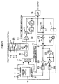
Fig. 1 shows the configuration of the signal processing circuit of an angular velocity sensor of the first embodiment according to the present invention. -
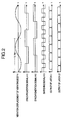
Fig. 2 is a timing chart of the signal processing circuit of an angular velocity sensor of the first embodiment according to the present invention. -
Fig. 3 shows the configuration of the signal processing circuit of an angular velocity sensor of the second embodiment according to the present invention. -
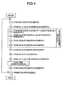
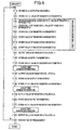
Fig. 4 is a flowchart of the signal processing program of an angular velocity sensor of the second embodiment according to the present invention. -
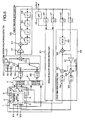
Fig. 5 shows the configuration of the signal processing circuit of an angular velocity sensor of the third embodiment according to the present invention. -
Fig. 6 is a timing chart of the signal processing circuit of the angular velocity sensor of the third embodiment according to the present invention. -
Fig. 7 shows the configuration of the signal processing circuit of an angular velocity sensor of the fourth embodiment according to the present invention. -
Fig. 8 is a flowchart of the signal processing program of an angular velocity sensor of the fourth embodiment according to the present invention. - Hereinafter, the embodiments of the present invention will be described using
Figs. 1 to 8 . -
Fig. 1 is a block diagram of the control circuits of an angular velocity sensor ofEmbodiment 1.Fig. 2 is a timing chart of the control circuit of an angular velocity sensor ofEmbodiment 1. Adetection element 1 of the angular velocity sensor of the present embodiment includes: - a vibrating
body 4 having a designated mass and vibrating in the vibration axis direction of the arrow inFig. 1 at a designated vibration frequency fd; -
fixed electrodes 3 and 6 (displacement detection units) arranged facing vibratingbody 4 and detecting, with changes in the capacitance, the displacement arising in vibratingbody 4 in a direction perpendicular to the axis of vibration by means of the Coriolis force arising from the application of the angular velocity; and -
fixed electrodes body 4 so as to negate the Coriolis force acting on vibratingbody 4. - Also, the signal processing part includes: a
capacitive detector 7 detecting the displacement due to the Coriolis force on vibratingbody 4 by detecting the difference between the capacitance between vibratingbody 4 and fixedelectrode 3 and the capacitance between vibratingbody 4 and fixedelectrode 6;
an A/D converter 8 converting the output ofcapacitive detector 7 into a digital signal;
a 2-slot time divisionsynchronous detection part 28 which has: aswitch 9 switching, with a signal Φ3 having a frequency which is four times greater than drive frequency fd, between two signals having a frequency of drive frequency fd as shown inFig. 2 , signal Φ1 lagging in phase by 90 degrees with respect to the vibration displacement of vibratingbody 4 and a signal Φ2 having the same phase as the vibration displacement of vibratingbody 4, and asynchronous detection part 10 multiplying the output thereof;
a 2-slot timedivision integration part 11 having a coefficient multiplier 12 determining the integration gain, anadder 13 carrying out integral calculations, and a shift register includingdelay circuits
alatch circuit 16 holding the output ofadder 13 at times during which the state of switching signal Φ3 is "1";
alatch circuit 17 holding the output ofadder 13 at times during which the state of switching signal Φ3 is "0";
an LPF (Low Pass Filter) 18 extracting the DC component of the output oflatch circuit 16; and
an angular velocityvibration control unit 27 which has: - a
multiplier 19 generating a signal, with the frequency being drive frequency fd and lagging in phase by 90 degrees with respect to the vibration displacement of vibratingbody 4, by multiplying the output oflatch circuit 16 with the inverted signal of signal Φ2 and taking the output oflatch circuit 16 to be an amplitude value, - a
multiplier 20 generating a signal, with the frequency being drive frequency fd and coinciding in phase with the vibration displacement of vibratingbody 4, by multiplying the output oflatch circuit 17 with signal Φ1 and taking the output oflatch circuit 17 to be an amplitude value, - an
adder 21 creating the added signal ofmultiplier 19 and multiplier 20, - an
adder 23 adding a fixed bias voltage Vb to the output ofadder 21, - a D/
A converter 25 converting the output ofadder 23 to an analog signal voltage in order to impress it onfixed electrode 5, - an
inverter 22 inverting the signal ofadder 21, - an
adder 24 adding fixed bias voltage Vb to inverter 22, and - a D/
A converter 26 converting the output ofadder 24 to an analog signal voltage in order to impress it onfixed electrode 2. - Next, an explanation will be given regarding the operation of the control circuit of
Fig. 1 . In the angular velocity sensor of the present embodiment, the displacement of vibratingbody 4 due to the Coriolis force acting on vibratingbody 4 is detected by means offixed electrodes capacitive detector 7. And then, there is carried out the action of negating the leakage vibration from the vibration axis direction, resulting from the Coriolis force acting on vibratingbody 4 and structural warps and the like of the vibrating body, by impressing a voltage onfixed electrodes body 4 due to the Coriolis force and leakage vibrations arising in a direction perpendicular to the axis of vibration. And then, a part of the feedback voltage during servo control is considered to be an angular velocity detection signal and is output. Initially, synchronous detection, with respect to the displacement signal of the vibrating body obtained viacapacitive detector 7 and A/D converter 8, is carried out with 2-slot time divisionsynchronous detection part 28 by means of synchronization signal Φ1 shown inFig. 2 and the vibration displacement (hereinafter called the Coriolis component) in the direction perpendicular to the axis of vibration. Next, in 2-slot timedivision integration part 11, the signal obtained with 2-slot time divisionsynchronous detection part 28 is integrated. In the same way, synchronous detection with respect to the displacement signal of the vibrating body is carried out by means of synchronization signal Φ2 shown inFig. 2 and the vibration displacement (hereinafter called the "error component") leaking in from the direction of the axis of vibration is detected and integrated. And then, in order to feed back the signal obtained in 2-slot timedivision integration part 11 to vibratingbody 4, in angular velocityvibration control part 27, the inverted signal of signal Φ2, shown inFig. 2 with respect to the Coriolis component, is multiplied inmultiplier 19, and a feedback signal is generated with respect to the vibration displacement due to the angular velocity in a direction perpendicular to the axis of vibration of vibratingbody 4. Also, with respect to the error component, signal Φ1 shown inFig. 2 is multiplied inmultiplier 20 and there is generated a feedback signal with respect to the leakage vibration displacement from the vibrations in the direction of the axis of vibration of vibratingbody 4. Inadder 21, the aforementioned two feedback signals are combined and at the very end, DC bias voltage Vb is added thereto inadders electrodes body 4. Also, the output oflatch circuit 16 in a state in which this vibration is negated is processed inlow pass filter 18 and the output voltage corresponding to the angular velocity is obtained. In the present embodiment, by switching, with switching signal Φ3 having a frequency eight times that of fd, signals Φ1 and Φ2, multiplied with the vibration displacement signal insynchronous detection part 10, by means ofswitch 9, synchronous detection of the vibration displacement signal is carried out with two phases. Next, by carrying out the data shifting operation of the shift register constituted bydelay circuits frequency 8×fd. By means of the aforementioned processing, there are respectively implemented two servo operations with a frequency of 4×fd. - Next, an angular velocity
sensor representing Embodiment 2 of the present invention will be explained by means ofFig. 3 andFig. 4 .Fig. 3 is a block diagram of the signal processing circuits of an angular velocity sensor ofEmbodiment 2.Fig. 4 is a flowchart of the control program of the angular velocity sensor ofEmbodiment 2. The present embodiment is one indicating a configuration, inEmbodiment 1 ofFig. 1 , in which 2-slot time divisionsynchronous detection part 28 and 2-slot timedivision integration part 11 are implemented by means of a Digital Signal Processor (DSP) and a control program therefor. ADSP part 30 includes: - an
input port 31 sampling and holding an input signal; - a
calculation part 32 using the data held by the input port and, in accordance with sequentially input command codes from acontrol program part 35, executing calculations such as multiplications, divisions, additions, and subtractions; - an
output port 33 temporarily storing the calculation result obtained incalculation part 32 and making outputs to the outside; and - a
program counter 34 outputting to control part 35 a stored address signal of a command code to be input.Control program part 35 stores command codes controllingDSP part 30, is a function outputting toDSP part 30 command codes stored in memory addresses corresponding to address signals input fromprogram counter 34, and can be implemented with a general-purpose Read Only Memory (ROM). Atiming adjustment part 68 is a function adjusting the timing of the transfer of data between hardware on the input side and output side ofDSP part 30 and the control program executed in the interior ofDSP part 30. Specifically, thetiming adjustment part 68 has alatch circuit 65 latching the output data of A/D converter 8 at the intermediate points in time of the high-level intervals and the intermediate points in time of the low-level intervals, of switching signal Φ3 shown in the timing chart ofFig. 2 ; - and two
latch circuits DSP part 30 by means ofcontrol program part 35, in order to satisfy the output timing positions of latches L1 and L2 shown in the timing chart ofFig. 2 . - Next, regarding the operation, it will be explained with the flowchart of
Fig. 4 . The terms "Register A" to "Register E" inside the flowchart indicate registers temporarily storing input data, calculation results, as well as output data in the interior of the DSP. First, the power supply is put in the ON state and if an initial reset is released, program counter 34 starts operating, executes consecutively the command codes ofStep 1 to Step 11 stored incontrol program 35, and, as long as there comes no processing termination instruction, returns to the command code ofStep 1 and repeatedly executes a series of processes. The cycle interval from the command code ofStep 1 to that ofStep 11 is 1/fd and the 2-slot time division integration process executed during a cycle inSteps 3 to 6 is executed twice, for the Coriolis component and the error component. According to the aforementioned processing, processing equivalent to that ofEmbodiment 1 is implemented. - Next, an angular velocity
sensor representing Embodiment 3 of the present invention will be explained by means ofFig. 5 andFig. 6 .Fig. 5 is a block diagram of the signal processing circuits of an angular velocity sensor ofEmbodiment 3.Fig. 6 is a timing chart of the signal processing circuit of the angular velocity sensor ofEmbodiment 3. The present embodiment is a configuration in which a drive axis direction vibration control function has been added toEmbodiment 1 ofFig. 1 . With respect toEmbodiment 1, an explanation regarding modifications and added functions will be given hereinafter. Indetection element 1, fixedelectrodes body 4 with changes in the capacitance. Also, fixedelectrodes body 4. - The signal processing circuit shown in
Fig. 5 includes: - a
capacitive detector 41 detecting the vibration direction displacement acting on vibratingbody 4 by detecting the difference between the capacitance between vibratingbody 4 and fixedelectrode 61 and the capacitance between vibratingbody 4 and fixedelectrode 62; - an A/
D converter 42 converting the output ofcapacitive detector 41 into a digital signal; - a 4-slot time division
synchronous detection part 57 having:- a
switch 43 switching the output of A/D converter 8 and the output of A/D converter 42 by means of a signal Φ4 with a frequency equal to that of switching signal Φ3 as shown in the timing chart ofFig. 5 and lagging in phase by 90 degrees with respect to signal Φ3, - a
switch 9 switching signal Φ1 and signal Φ2 with signal Φ3, and - a
synchronous detection part 10 multiplying the output thereof;
division integration part 56 composed of:- a
coefficient multiplier 12 determining an integration gain, - an
adder 13 carrying out integration calculations, and - a shift register composed of
delay circuits - latch
circuits adder 13 with the four combinations of the states "1" and "0" of switching signal Φ3 and the states "1" and "0" of switching signal Φ4; and - a drive
vibration control part 48 having:- a VCO (Voltage Controlled Oscillator) 49 being a voltage controlled oscillator and outputting an AC signal of a frequency corresponding to the outputs of
latch circuit 46, - a
multiplier 50 multiplying the output oflatch circuit 47 and the output ofVCO 49, - an
adder 52 adding a fixed bias voltage Vb to the output ofmultiplier 50, - a D/
A converter 54 converting the output ofadder 52 into an analog signal voltage for impressing on fixedelectrode 64, - an
inverter 51 inverting the signal ofmultiplier 50, - an
adder 53 adding a fixed bias voltage Vb to inverter 51, and - a D/
A converter 55 converting the output ofadder 53 into an analog signal voltage for impressing on fixedelectrode 63.
- a VCO (Voltage Controlled Oscillator) 49 being a voltage controlled oscillator and outputting an AC signal of a frequency corresponding to the outputs of
- a
- Next, an explanation will be given regarding the operation. In the angular velocity sensor of the present embodiment, an AC voltage is impressed on fixed
electrodes body 4 vibrate in the vibration axis direction and the displacement (amplitude and frequency) in the vibration axis direction of vibratingbody 4 due thereto is detected by means of fixedelectrodes capacitive detector 41. And then, due to the electrostatic force generated by means of the voltage impressed on fixedelectrodes body 4 have designated values. Also, similarly toEmbodiment 1, the displacement of vibratingbody 4 due to the Coriolis force is detected by means of fixedelectrodes capacitive detector 7. And then, by means of the electrostatic force generated by the voltage impressed onfixed electrodes body 4 due to the Coriolis force and leakage vibration arising in a direction perpendicular to the axis of vibration to zero. And then, a part of the feedback voltage at that time is considered to be the angular velocity detection signal and extracted. Specifically, as for the operation, with respect to the signal of the displacement in the direction of the axis of vibration obtained throughcapacitive detector 41 and A/D converter 42 and the signal of displacement in a direction perpendicular to the axis of vibration, obtained throughcapacitive detector 7 and A/D converter 8, four-way synchronous detection based on the combination of the states of signals Φ1 and Φ2 and signals Φ3 and Φ4 is executed with time division, as shown in the timing chart ofFig. 6 , with 4-slot time divisionsynchronous detection part 57. This processing is executed four times perinterval 1/fd, being the period. Next, in 4-slot timedivision integration part 56, the signals obtained in 4-slot time divisionsynchronous detection part 57 are integrated consecutively. Simultaneously therewith, each integral calculation result, being the output ofadder 13, is stored and shifted in the shift register composed ofdelay circuits division integration part 56 to vibratingbody 4, the outputs of 4-slot timedivision integration part 56 are stored inlatch circuits vibration control part 27 with the contents described inEmbodiment 1, and by inputting the same to fixedelectrodes body 4, the vibration displacement in the direction perpendicular to the axis of vibration is negated. On the other hand, in order to carry out control in the direction of the vibration axis, the outputs of 4-slot timedivision integration part 56 are stored inlatch circuits vibration control part 48, and, by inputting the same in fixedelectrodes body 4, a vibration of vibratingbody 4 with designated amplitude and frequency in the direction of the axis of vibration is implemented. - Next, an angular velocity
sensor representing Embodiment 4 of the present embodiment will be explained by means ofFig. 7 andFig. 8 .Fig. 7 is a block diagram of the signal processing circuits of the angular velocity sensor ofEmbodiment 4.Fig. 8 is a flowchart of the signal processing program of an angular velocity sensor ofEmbodiment 4. In the present embodiment, there is a configuration implementing, by means of a Digital Signal Processor (DSP) described inEmbodiment 2 ofFig. 3 and the control program thereof, 4-slot time divisionsynchronous detection part 57 and 4-slot timedivision integration part 56 found inEmbodiment 3 ofFig. 5 . Also, atiming adjustment part 72 has the function of regulating the timing of data transfers between the hardware on the input side and output side ofDSP part 30 and the control program executing insideDSP part 30. Specifically, thetiming adjustment part 72 is composed of: - latching
circuit 65 latching the output data of A/D converter 8 at the respective intermediate points in time of the high-level and low-level intervals, of switching signal Φ3 shown inFig. 6 ; - a latching
circuit 69 latching the A/D conversion output data at the respective intermediate points in time of the high-level and low-level intervals, of switching signal Φ4 shown inFig. 6 ; and - four
latch circuits DSP part 30 bycontrol program part 35, in order to satisfy the output timing of latch circuits L1 to L4 shown in the timing chart ofFig. 6 . - Next, regarding the operation, an explanation will be given with the flowchart of
Fig. 8 . E.g., when the power supply is put in the ON state, program counter 34 starts operation, executes consecutively the command codes ofSteps 1 to 19 stored incontrol program 35, and, as long as there comes no processing termination instruction, returns to command code ofStep 1 and repeatedly executes a series of processes. During one cycle fromStep 1 to Step 19, the 4-slot time division integration processing implemented inSteps 3 to 8 is executed four times for the angular velocity vibration control (Coriolis component and error component) and for the drive vibration control (amplitude and frequency). - It should be further understood by those skilled in the art that although the foregoing description has been made on embodiments of the invention, the invention is not limited thereto and various changes and modifications may be made without departing from the spirit of the invention and the scope of the appended claims.
Claims (8)
- An angular velocity detecting apparatus, having a vibrating body (4) capable of displacement in a first direction and a second direction being mutually orthogonal with each other, and, in a state where the vibrating body has been made to vibrate in the first direction, detecting the displacement level when the vibrating body has been displaced in the second direction due to the generation of angular velocity, wherein
the angular velocity detecting apparatus comprises means for dividing in time and executing vibration operation in said first direction and displacement level detection operation in said second direction. - The angular velocity detecting apparatus according to Claim 1, wherein
operating parameters of the vibration operation in said first direction are vibration amplitude and vibration frequency. - The angular velocity detecting apparatus according to Claim 1 or 2, wherein
said operation of detecting displacement level in the second direction includes servo control acting to suppress the displacement level generated by angular velocity and servo control acting to suppress displacement due to leakage vibration from the first direction. - An angular velocity detecting apparatus, having a vibrating body (4) capable of displacement in a first direction and a second direction being mutually orthogonal with each other, and having servo control means for operating, in a state where the vibrating body has been made to vibrate in the first direction, to suppress displacement of the vibrating body toward the second direction due to the generation of angular velocity, wherein
the angular velocity detecting apparatus comprises means for dividing in time and executing a plurality of servo control calculations. - The angular velocity detecting apparatus according to Claim 4, wherein
operating parameters of the vibration operation in said first direction are vibration amplitude and vibration frequency. - The angular velocity detecting apparatus according to Claim 4 or 5, wherein
said servo control means executes a servo control acting to suppress the displacement level generated by angular velocity and a servo control acting to suppress displacement due to leakage vibration from the first direction. - An angular velocity detecting apparatus, having a vibrating body (4) capable of displacement in a first direction and a second direction being mutually orthogonal with each other, and, in a state where the vibrating body (4) has been made to vibrate in the first direction, detecting the displacement level when the vibrating body has been displaced in the second direction due to the generation of angular velocity, wherein
the angular velocity detecting apparatus comprises:a microcomputer or Digital Signal Processor (30) executing control for vibration operation in the first direction or control for displacement level detection in the second direction;means (27) for storing a control program, for control for said vibration operation or control for said displacement level detection operation; andmeans (68) for regulating the data input and output timing of a circuit part connected with said microcomputer or Digital Signal Processor (30). - An angular velocity detecting apparatus, comprising:a vibrating body (4);force application means (2, 5; 63, 64) for applying a force on said vibrating body;excitation means (48) for controlling said force application means (63, 64) to make said vibrating body (4) vibrate;detection means (3, 6, 7; 41, 61, 62) for detecting a level on the basis of the displacement of said vibrating body (4);control means (27) for controlling said force application means (2, 5) or said excitation means (48) so as to negate said displacement;time division means (9) for dividing time between a signal (Φ1) from said detection means, taken to be the first signal, and a second signal (Φ2), lagging in phase by nearly 90 degrees with respect to said first signal (Φ1);processing means (11) for separately processing time-divided first signal (Φ1) and second signal (Φ2);combination means (21) for combining the processed said first signal (Φ1) and said second signal (Φ2); andsaid control means (27) controlling said force application means (2, 5; 63, 64) or said excitation means (48) on the basis of a signal from said combination means (21) to detect an angular velocity on the basis of the controlled level.
Applications Claiming Priority (1)
| Application Number | Priority Date | Filing Date | Title |
|---|---|---|---|
| JP2008303376A JP5244562B2 (en) | 2008-11-28 | 2008-11-28 | Angular velocity detector |
Publications (2)
| Publication Number | Publication Date |
|---|---|
| EP2199740A2 true EP2199740A2 (en) | 2010-06-23 |
| EP2199740A3 EP2199740A3 (en) | 2016-10-12 |
Family
ID=42136247
Family Applications (1)
| Application Number | Title | Priority Date | Filing Date |
|---|---|---|---|
| EP09177080.0A Withdrawn EP2199740A3 (en) | 2008-11-28 | 2009-11-25 | Angular velocity detecting apparatus |
Country Status (3)
| Country | Link |
|---|---|
| US (1) | US20100132462A1 (en) |
| EP (1) | EP2199740A3 (en) |
| JP (1) | JP5244562B2 (en) |
Families Citing this family (3)
| Publication number | Priority date | Publication date | Assignee | Title |
|---|---|---|---|---|
| JP4576441B2 (en) * | 2008-03-21 | 2010-11-10 | 日立オートモティブシステムズ株式会社 | Angular velocity sensor |
| DE102014010056B4 (en) * | 2014-07-07 | 2016-02-25 | Northrop Grumman Litef Gmbh | A control device and method for minimizing scale factor errors of a rotation rate sensor |
| CN105044381B (en) * | 2015-09-08 | 2018-07-17 | 中国核动力研究设计院 | Tach signal processing method for nuclear-power reactor coolant pump |
Citations (3)
| Publication number | Priority date | Publication date | Assignee | Title |
|---|---|---|---|---|
| JPH05296771A (en) | 1992-04-17 | 1993-11-09 | Murata Mfg Co Ltd | Vibrogyro |
| JP3603501B2 (en) | 1996-09-25 | 2004-12-22 | 株式会社村田製作所 | Angular velocity detector |
| JP3729191B2 (en) | 1998-10-23 | 2005-12-21 | トヨタ自動車株式会社 | Angular velocity detector |
Family Cites Families (13)
| Publication number | Priority date | Publication date | Assignee | Title |
|---|---|---|---|---|
| US5646346A (en) * | 1994-11-10 | 1997-07-08 | Okada; Kazuhiro | Multi-axial angular velocity sensor |
| JPH08282937A (en) * | 1995-04-18 | 1996-10-29 | Hitachi Building Syst Eng & Service Co Ltd | Running characteristic inspection device for elevator |
| JPH08297028A (en) * | 1995-04-26 | 1996-11-12 | Canon Inc | Angular velocity detecting apparatus |
| JP4729801B2 (en) * | 2000-03-17 | 2011-07-20 | アイシン精機株式会社 | Vibrator driving device and angular velocity sensor provided with the vibrator driving device |
| DE10248735B4 (en) * | 2002-10-18 | 2004-10-28 | Litef Gmbh | Method for electronically tuning the read oscillation frequency of a Coriolis gyro |
| JP2004347530A (en) * | 2003-05-23 | 2004-12-09 | Alps Electric Co Ltd | Electrostatic capacitance type sensor |
| JP3894925B2 (en) * | 2004-03-19 | 2007-03-22 | 日本航空電子工業株式会社 | Closed loop optical fiber gyro |
| JP4375098B2 (en) * | 2004-04-23 | 2009-12-02 | パナソニック電工株式会社 | Angular velocity sensor |
| EP1624286B1 (en) * | 2004-08-03 | 2017-10-04 | STMicroelectronics Srl | Micro-electro-mechanical sensor with force feedback loop |
| JP5117716B2 (en) * | 2006-02-14 | 2013-01-16 | セイコーインスツル株式会社 | Mechanical quantity sensor |
| JP2007285958A (en) * | 2006-04-19 | 2007-11-01 | Denso Corp | Sensor circuit for gyro-sensor |
| JP2009216436A (en) * | 2008-03-07 | 2009-09-24 | Denso Corp | Angular velocity detection apparatus |
| JP2011058860A (en) * | 2009-09-08 | 2011-03-24 | Hitachi Automotive Systems Ltd | Angular-velocity detecting apparatus |
-
2008
- 2008-11-28 JP JP2008303376A patent/JP5244562B2/en active Active
-
2009
- 2009-11-24 US US12/625,142 patent/US20100132462A1/en not_active Abandoned
- 2009-11-25 EP EP09177080.0A patent/EP2199740A3/en not_active Withdrawn
Patent Citations (3)
| Publication number | Priority date | Publication date | Assignee | Title |
|---|---|---|---|---|
| JPH05296771A (en) | 1992-04-17 | 1993-11-09 | Murata Mfg Co Ltd | Vibrogyro |
| JP3603501B2 (en) | 1996-09-25 | 2004-12-22 | 株式会社村田製作所 | Angular velocity detector |
| JP3729191B2 (en) | 1998-10-23 | 2005-12-21 | トヨタ自動車株式会社 | Angular velocity detector |
Also Published As
| Publication number | Publication date |
|---|---|
| US20100132462A1 (en) | 2010-06-03 |
| JP2010127794A (en) | 2010-06-10 |
| EP2199740A3 (en) | 2016-10-12 |
| JP5244562B2 (en) | 2013-07-24 |
Similar Documents
| Publication | Publication Date | Title |
|---|---|---|
| JP4885245B2 (en) | RD converter and angle detection device | |
| US8113051B2 (en) | Angular velocity measuring device | |
| EP2199740A2 (en) | Angular velocity detecting apparatus | |
| JP2011064515A (en) | Angular speed and acceleration detector | |
| JP2010151669A (en) | Physical quantity detection circuit and physical quantity sensor device | |
| EP2306148A2 (en) | Angular velocity detecting apparatus | |
| EP1615343B1 (en) | Method of converting an analog signal into a digital signal | |
| JP5183374B2 (en) | Angular velocity detector | |
| JP2000337925A (en) | R/d converter | |
| JP5227977B2 (en) | Angular velocity sensor | |
| JP2011061929A (en) | Motor speed control device | |
| JP4700485B2 (en) | Arithmetic apparatus and test apparatus | |
| JP5823785B2 (en) | Rotation angle detector | |
| JP2011067016A (en) | Servo controller | |
| CN109416378B (en) | System and method for providing amplitude and phase delay of sinusoidal signals | |
| JP6826524B2 (en) | Signal processing device and signal processing method | |
| JP7225621B2 (en) | Servo controller | |
| Kurumatani et al. | System-on-a-chip including generic framework of motion controller using disturbance observer based acceleration controller | |
| JP2527008B2 (en) | Frequency / phase estimation device | |
| JP3870274B1 (en) | Trigonometric function computing device and trigonometric function computing method | |
| JPH10135742A (en) | Signal waveform generation device | |
| JP2006086681A (en) | Data corrector and correction method of a-d converter | |
| JPH0353601A (en) | Sinusoidal wave oscillation circuit | |
| JPH0296664A (en) | Apparatus for estimating frequency and phase | |
| JPH0432306A (en) | Sinusoidal wave oscillation circuit |
Legal Events
| Date | Code | Title | Description |
|---|---|---|---|
| PUAI | Public reference made under article 153(3) epc to a published international application that has entered the european phase |
Free format text: ORIGINAL CODE: 0009012 |
|
| 17P | Request for examination filed |
Effective date: 20100226 |
|
| AK | Designated contracting states |
Kind code of ref document: A2 Designated state(s): AT BE BG CH CY CZ DE DK EE ES FI FR GB GR HR HU IE IS IT LI LT LU LV MC MK MT NL NO PL PT RO SE SI SK SM TR |
|
| RAP1 | Party data changed (applicant data changed or rights of an application transferred) |
Owner name: HITACHI AUTOMOTIVE SYSTEMS, LTD. |
|
| RAP1 | Party data changed (applicant data changed or rights of an application transferred) |
Owner name: HITACHI AUTOMOTIVE SYSTEMS, LTD. |
|
| PUAL | Search report despatched |
Free format text: ORIGINAL CODE: 0009013 |
|
| AK | Designated contracting states |
Kind code of ref document: A3 Designated state(s): AT BE BG CH CY CZ DE DK EE ES FI FR GB GR HR HU IE IS IT LI LT LU LV MC MK MT NL NO PL PT RO SE SI SK SM TR |
|
| RIC1 | Information provided on ipc code assigned before grant |
Ipc: G01C 19/56 20120101AFI20160907BHEP |
|
| STAA | Information on the status of an ep patent application or granted ep patent |
Free format text: STATUS: EXAMINATION IS IN PROGRESS |
|
| 17Q | First examination report despatched |
Effective date: 20180925 |
|
| STAA | Information on the status of an ep patent application or granted ep patent |
Free format text: STATUS: EXAMINATION IS IN PROGRESS |
|
| STAA | Information on the status of an ep patent application or granted ep patent |
Free format text: STATUS: THE APPLICATION IS DEEMED TO BE WITHDRAWN |
|
| 18D | Application deemed to be withdrawn |
Effective date: 20210601 |