EP2199213B1 - Machine et procédé de conditionnement - Google Patents
Machine et procédé de conditionnement Download PDFInfo
- Publication number
- EP2199213B1 EP2199213B1 EP10001873A EP10001873A EP2199213B1 EP 2199213 B1 EP2199213 B1 EP 2199213B1 EP 10001873 A EP10001873 A EP 10001873A EP 10001873 A EP10001873 A EP 10001873A EP 2199213 B1 EP2199213 B1 EP 2199213B1
- Authority
- EP
- European Patent Office
- Prior art keywords
- product
- web
- nip
- webs
- label
- Prior art date
- Legal status (The legal status is an assumption and is not a legal conclusion. Google has not performed a legal analysis and makes no representation as to the accuracy of the status listed.)
- Active
Links
Images


Classifications
-
- B—PERFORMING OPERATIONS; TRANSPORTING
- B65—CONVEYING; PACKING; STORING; HANDLING THIN OR FILAMENTARY MATERIAL
- B65B—MACHINES, APPARATUS OR DEVICES FOR, OR METHODS OF, PACKAGING ARTICLES OR MATERIALS; UNPACKING
- B65B9/00—Enclosing successive articles, or quantities of material, e.g. liquids or semiliquids, in flat, folded, or tubular webs of flexible sheet material; Subdividing filled flexible tubes to form packages
- B65B9/02—Enclosing successive articles, or quantities of material between opposed webs
-
- B—PERFORMING OPERATIONS; TRANSPORTING
- B65—CONVEYING; PACKING; STORING; HANDLING THIN OR FILAMENTARY MATERIAL
- B65B—MACHINES, APPARATUS OR DEVICES FOR, OR METHODS OF, PACKAGING ARTICLES OR MATERIALS; UNPACKING
- B65B35/00—Supplying, feeding, arranging or orientating articles to be packaged
- B65B35/10—Feeding, e.g. conveying, single articles
-
- B—PERFORMING OPERATIONS; TRANSPORTING
- B65—CONVEYING; PACKING; STORING; HANDLING THIN OR FILAMENTARY MATERIAL
- B65B—MACHINES, APPARATUS OR DEVICES FOR, OR METHODS OF, PACKAGING ARTICLES OR MATERIALS; UNPACKING
- B65B59/00—Arrangements to enable machines to handle articles of different sizes, to produce packages of different sizes, to vary the contents of packages, to handle different types of packaging material, or to give access for cleaning or maintenance purposes
- B65B59/001—Arrangements to enable adjustments related to the product to be packaged
-
- B—PERFORMING OPERATIONS; TRANSPORTING
- B65—CONVEYING; PACKING; STORING; HANDLING THIN OR FILAMENTARY MATERIAL
- B65B—MACHINES, APPARATUS OR DEVICES FOR, OR METHODS OF, PACKAGING ARTICLES OR MATERIALS; UNPACKING
- B65B59/00—Arrangements to enable machines to handle articles of different sizes, to produce packages of different sizes, to vary the contents of packages, to handle different types of packaging material, or to give access for cleaning or maintenance purposes
- B65B59/003—Arrangements to enable adjustments related to the packaging material
-
- B—PERFORMING OPERATIONS; TRANSPORTING
- B65—CONVEYING; PACKING; STORING; HANDLING THIN OR FILAMENTARY MATERIAL
- B65B—MACHINES, APPARATUS OR DEVICES FOR, OR METHODS OF, PACKAGING ARTICLES OR MATERIALS; UNPACKING
- B65B59/00—Arrangements to enable machines to handle articles of different sizes, to produce packages of different sizes, to vary the contents of packages, to handle different types of packaging material, or to give access for cleaning or maintenance purposes
- B65B59/02—Arrangements to enable adjustments to be made while the machine is running
Definitions
- the present invention relates to an apparatus for packaging products for shipping.
- Mail-order companies and other organizations that deliver products by mail or courier are continually striving to improve the efficiency of the processes of packaging products and getting them ready for shipment, which generally includes labeling (i.e., affixing a label on each package indicating the address of the recipient), and franking (i.e., putting the correct postage on each package).
- labeling i.e., affixing a label on each package indicating the address of the recipient
- franking i.e., putting the correct postage on each package.
- the processes of labeling and franking are performed at least in part by hand.
- GB 2,253,385 discloses an apparatus in accordance with the pre-characterising section of claim 1.
- an apparatus for packaging products comprising: a pair of opposed rollers forming a nip therebetween; a web guide system for guiding a pair of opposing upper and lower webs of flexible packaging material into the nip so that a product to be packaged when placed between the webs is passed through the nip along with the webs, facing surfaces of the webs having sealing material for sealing the webs together enclosing the product; and an infeed bed located upstream of the nip, the lower web being supported by the infeed bed such that a product to be packaged can be placed onto the lower web on the infeed bed and advanced along with the lower web in a longitudinal direction into the nip; and characterised by: a generally planar labeling support member spaced upstream of the nip; wherein the web guide system includes upper web guides structured and arranged to guide the upper web to travel along an upper surface of the labeling support member such that the upper web
- an automated label applicator affixes the label to the flexible packaging material.
- the system includes verifying whether the label was affixed by the label applicator, and the web drive system advances the webs and the product through the nip only after it has been verified that the label was affixed.
- the affixing can be accomplished manually or by using an automated label applicator.
- FIG. 1 A packaging apparatus 20 in accordance with one embodiment of the invention is shown in FIG. 1 .
- the apparatus 20 is of the dual-web type for advancing a first or upper web 22 and a second or lower web 24 in generally parallel opposing relation with an object disposed between the webs and sealing the webs together to capture the object therebetween.
- the apparatus includes a main frame having a base formed by a plurality of spaced vertical support columns 26, 28, 30 , on one side of a longitudinal axis of the apparatus, and a corresponding plurality of spaced vertical support columns 26', 28', 30' (column 30' not visible in FIG. 1 ) on the opposite side of the longitudinal axis.
- Upper and lower longitudinal members 32 are rigidly connected between support columns 26 and 28 and between support columns 28 and 30
- similar longitudinal members 32 ' are rigidly connected between columns 26' and 28' and between columns 28 ' and 30'.
- a lower transverse member 34 is rigidly connected between the support columns 26 and 26'
- a lower transverse member 36 is rigidly connected between the support columns 28 and 28'
- a lower transverse member 38 is rigidly connected between the support columns 30 and 30' .
- a generally planar infeed bed 40 is rigidly connected between the longitudinal members 32 , 32' .
- a lower longitudinal member 42 is rigidly connected between the lower transverse members 36 and 38.
- the main frame also includes a superstructure that extends up from the base and above the infeed bed 40 .
- the superstructure is formed by upward extensions of the support columns 26, 26', 28, 28', 30, and 30' .
- An upper transverse member 44 is rigidly connected between the upper ends of the columns 26 and 26'
- an upper transverse member 46 is rigidly connected between the upper ends of the columns 30 and 30' .
- An upper longitudinal member 48 is rigidly connected between the upper ends of the columns 26 and 30
- an upper longitudinal member 50 is rigidly connected between the upper ends of the columns 26' and 30' .
- Upstream columns 26 and 26' support web mounts 52, 54 that respectively support supply rolls of the webs 22, 24 in a rotatable manner.
- the upper web 22 is drawn from its supply roll and advanced over a guide 56 supported between the longitudinal members 48, 50, then over a guide 58 supported between the longitudinal members 48, 50 and spaced longitudinally downstream from the first guide 56 , and then downward for further handling as described in detail below.
- the lower web 24 is drawn from its supply roll and advanced under a lower guide 60 supported between columns 28, 28' , then over an upper guide 62 supported between columns 28, 28' , then onto the upper surface of the infeed bed 40 .
- the infeed bed supports a pair of web edge guides 64, 66 that extend parallel to the longitudinal axis of the machine and are spaced apart by a distance about equal to the width of the lower web 24 .
- the edge guides capture the opposite edges of the web 24 between the infeed bed and the guides and thereby hold the lower web flat on the infeed bed and substantially prevent transverse movement of the web, while allowing the web to freely move in the longitudinal direction.
- a product P to be packaged is placed upon the lower web 24 on the infeed bed, as further described below.
- the apparatus includes a pair of rollers 70, 72 that are rotatably mounted in the main frame at a downstream end thereof.
- the rollers 70, 72 form a nip through which the webs 22, 24 are advanced with the product P disposed therebetween.
- one or both of the rollers 70 , 72 comprises a resiliently deformable material at least over a medial portion of the roller's length, such that the passage of the product through the nip deforms the roller(s) and the restoring force of the resiliently deformable material presses the webs 22, 24 toward each other so that the web conform closely to the product.
- the webs advantageously have cold seal or cohesive material on their facing surfaces such that the application of pressure by the rollers 70, 72 causes the webs to adhere to each other but not to the product.
- the end portions of each of the rollers 70, 72 advantageously comprise a generally non-deformable material for firmly gripping the opposite edge portions of the webs 22, 24 , and the rollers advantageously are rotatably driven for advancing the webs through the apparatus, thus comprising a web drive system.
- a separate web drive system can be employed if desired.
- an upper web support plate 74 is mounted between a pair of spaced end plates 76 , forming a housing that rests atop the base of the main frame.
- This housing preferably is pivotable relative to the main frame about hinges (not shown) located at the upper downstream corner of the housing, for access to internal parts of the machine when required for maintenance and the like.
- the upper web support plate 74 is spaced vertically above the level of the infeed bed.
- the upper web is advanced beneath a pair of longitudinally spaced web guides 78, 80 supported atop the end plates 76 , such that the upper web passes along the upper surface of the support plate 74 .
- the support plate 74 provides support for the upper web 22 so that an adhesive label can be affixed onto the web either by hand or, in some embodiments as described below, by a labeling unit.
- the apparatus 20 also includes a module frame 82 , best seen in FIG. 2 .
- the module frame comprises a stand-alone module that is configured to support various components that tend to be specific to a particular user of the packaging apparatus, and that is configured to releasably dock with the main frame of the apparatus so that the components are positioned properly for operation during the packaging process.
- the module frame comprises a base formed by a pair of spaced longitudinal members 84, 86 each of which has wheels 88 such as caster wheels or the like for rolling the module frame along a floor, and a transverse member 90 rigidly connected between the longitudinal members 84, 86 .
- a vertical support column 92 extends upwardly from the base.
- a longitudinal support member 94 is rigidly connected to the column 92 in cantilever fashion and supports a generally horizontal platform 96 .
- the upper end portion of the support column 92 supports a fixture 98 configured to mount a labeling unit 100 .
- a customer terminal 102 comprising a microprocessor and memory (e.g., a personal computer), is mounted on the transverse member 90 of the module frame.
- a visual display monitor 104 , a keyboard 106 , and a mouse 108 are supported by the platform 96 and are connected to the customer terminal 102 .
- a product scanner 110 is also supported by the platform 96 .
- the module frame 82 includes releasable fastening devices 112 mounted on the longitudinal base member 84 .
- the fastening devices 112 are configured to releasably engage corresponding fastening devices 114 ( FIG. 1 ) on the longitudinal member 42 of the main frame of the apparatus so as to dock the module frame with the main frame.
- the labeling unit 100 comprises a printer 116 operable to print on adhesive labels that are preferably in the form of a continuous web of release liner material with the labels releasably adhered to the liner and spaced along its length direction.
- a roll 118 of the adhesive labels is mounted on the module frame adjacent the labeling unit.
- the label web is advanced through the printer, the printer prints on each label, and then the label is separated from the release liner for application to the upper web 22 .
- the labeling unit includes an automated label applicator 120 that receives the label from the printer.
- a sensor 122 FIG. 4 ) detects when a label has been received by the applicator, as further described below.
- the label applicator includes a suitable mechanism for holding onto the upper, non-adhesive side of the label, such as a vacuum-operated tamp head 124 .
- the tamp head 124 is movable by a suitable pneumatic cylinder or the like between an upper position and a lower position; in the lower position, the adhesive label held by the tamp head is pressed against the upper web 22 supported on the support plate 74 , thereby affixing the label to the web.
- a suitable labeling unit is the Model 250 print and apply labeling system available from RSI ID Technologies of Chula Vista, California; the system includes a Zebra thermal-transfer printer. Other types of printing devices can be used, including ink jet, laser jet, and the like.
- the upper web and lower web are advanced by the web drive system to pass through the nip between the rollers 70, 72 , along with the product P supported on the lower web 24 .
- the distance traveled by the upper web between the label application station and the nip is designed in relation to the distance traveled by the product from its initial location on the infeed bed to the nip so that the label on the upper web is generally centered on a package formed to envelope the product.
- a cutoff device 130 severs the web material at a location spaced downstream from the trailing edge of the product to produce a completed package.
- a package outfeed conveyor 132 receives the package and conveys it to another location such as into a bin (not shown).
- the apparatus 20 advantageously includes an infeed gate 140 suitably mounted (such as below the upper web support plate 74 ) in a position upstream of the nip defined by the rollers 70, 72 .
- the infeed gate is connected to an actuator 142 , such as a pneumatic cylinder or the like, operable to move the infeed gate between a blocking position wherein the lower edge of the gate abuts or nearly abuts the lower web 24 on the infeed bed 40 and an unblocking position wherein the lower edge of the gate is spaced above the lower web by a distance exceeding a maximum height of the products to be packaged such that the products can pass beneath the gate.
- an actuator 142 such as a pneumatic cylinder or the like
- the infeed gate is lowered to the blocking position and the product is placed on the lower web with the leading edge of the product abutting the gate. This ensures that the leading edge of the product is in a consistent, repeatable location with respect to the nip.
- the apparatus 20 also includes a product length detector 150 for measuring the length of a product disposed on the lower web 24 on the infeed bed 40 .
- the product length detector can comprise various types of devices, including but not limited to an optical distance-measuring device such as a laser distance-measuring device.
- the product length detector is preferably mounted adjacent an upstream end of the infeed bed 40 and is positioned and aimed at the trailing edge of the product disposed on the lower web.
- the length of the product between the leading and trailing edges can be determined.
- the apparatus 20 can include a scale 154 embedded in the infeed bed 40 in such a manner that the lower web 24 passes over the scale and the weight of a product disposed on the lower web is entirely supported by the scale.
- the infeed bed can have an aperture therein and the scale can be mounted beneath the aperture such that the upper surface of the scale is flush with the upper surface of the infeed bed.
- the total weight supported by the scale comprises the product plus a portion of the lower web; accordingly, a tare measurement of the lower web alone can be subtracted from the total weight to determine the product weight.
- the product weight is one component of the total weight of a package enclosing the product. The total package weight is determined in a manner described below.
- the apparatus includes a product scanner 110 .
- the product scanner is positioned above the infeed bed near the infeed gate 140 so that a product placed on the lower web against the gate can be scanned to detect a product code on the product or on an item that is packaged along with the product, such as a packing slip.
- the product code can be in the form of a bar code the encodes a universal product code or the like.
- the scanner can comprise a bar code reader. Based on the product code, information about the identity of the product and its characteristics (e.g., product weight, product length, product height, etc.) and other information associated with the product can be determined. Such information can be stored in the memory of the customer terminal 102 , for instance.
- the apparatus 20 includes a controller 160 comprising a microprocessor and memory (e.g., a personal computer or the like).
- the controller 160 is programmed to control the various motors and actuators of the apparatus 20 that effect movement of the moving parts such that the movements are properly synchronized with respect to one another and so that packages are properly made and labeled.
- FIG. 4 shows the interconnections between the controller 160 and certain components of the apparatus; in addition to the connections shown in FIG. 4 , it will be understood that the controller 160 is also connected to the motor 162 that drives the nip rollers 70, 72 , to the cutoff device 130 , to the motor 164 that drives the outfeed conveyor 132 , and to the actuator 142 for the infeed gate 140 . As depicted in FIG.
- the controller 160 is connected to the product length detector 150 and receives a signal therefrom.
- the detector 150 can be calibrated so that its signal is directly indicative of the product length; alternatively, the signal can be indicative of the distance from the detector to the trailing edge of the product, and the microprocessor of the controller 160 can be programmed to calculate the product length by subtracting that distance from a predetermined distance between the detector and the infeed gate 140 stored in the memory of the controller.
- the controller 160 is also connected to the product scanner 110 for receiving a signal therefrom indicative of the product code read by the scanner.
- the memory of the controller 160 can store a database that includes product information correlated with product codes, so that based on the product code indicated by the signal from the scanner 110 , information about the product can be retrieved from the database.
- the information can include, for example, the height of the product.
- the product height is important because the length of the packaging material webs 22, 24 required for packaging a product depends not only on the product length but also on the product height.
- the length of the fin i.e., the portion of web material that extends upstream of the product's leading edge and the portion that extends downstream of the product's trailing edge
- the fin length can be a multiple of the product height such that the greater the product height, the greater the fin length.
- product height must be known. This can be accomplished either by storing the predetermined product height in the database of the controller 160 and accessing it based on the scanned product code, or by using a product height detector.
- the product height detector can be incorporated into or mounted alongside the scanner 110 , or in another suitable location.
- the microprocessor of the controller 160 advantageously is programmed to calculate the length of the webs 22, 24 needed for packaging the product scanned by the scanner 110 .
- the required length depends on the product length and product height.
- the microprocessor is also programmed to calculate the weight of the required length of the webs 22, 24 based on the web length and a predetermined weight per unit length of the web material stored in the memory of the controller; thus, the weight of each web is equal to the length multiplied by the weight per unit length.
- the weight of each web can be calculated by multiplying the length by a predetermined weight per unit area or basis weight and multiplying that product by a predetermined width of the web material.
- the controller 160 is connected to the scale 154 , when a scale is present.
- the scale provides a signal indicative of the weight exerted on the scale and communicates the signal to the controller 160 .
- the scale advantageously is tared to effectively subtract the weight of the lower web (and taring preferably is performed before each product is weighed), such that the signal from the scale is directly indicative of the product weight.
- the microprocessor of the controller calculates the total package weight as the sum of the product and web material weights.
- the controller 160 is also connected to the labeling unit 100 for controlling its operation.
- the labeling unit includes a sensor 122 for detecting when a label has been received at the tamp head 124 of the label applicator 120 .
- the signal from the sensor 122 is received by the controller 160 .
- the microprocessor of the controller is programmed so that the web drive system is activated to advance the webs and product through the nip if and only if the sensor 122 confirms that a label was received at the tamp head, which gives a positive confirmation (once the tamp head is lowered against the upper web) that a label has been affixed to the upper web 22 .
- the label is printed and affixed only if the product code has been successfully scanned by the scanner 110 .
- the apparatus of the invention ensures that packages are made only if a good scan has been accomplished and a label has been printed and affixed.
- a cycle start button (not shown) is pressed, which causes the controller 160 to execute a series of operations as follows:
- the controller 160 causes the product scanner 110 to scan the product code, and the signal from the scanner is sent to the customer terminal 102 , which, based on the product code, accesses its database and retrieves information about the scanned product that will be used, among other things, for generating information to be printed on a label.
- the controller 160 also receives feedback from the scanner 110 to confirm the product was scanned.
- the scale 154 is tared and the product is weighed, and the product weight is stored in the memory of the controller 160 .
- the product length detector 150 measures the distance to the product's trailing edge and the microprocessor of the controller 160 calculates the product length based on that measured distance and the known distance to the infeed gate 140 where the product's leading edge is located.
- the microprocessor then calculates the length of the webs 22, 24 required for the package based on the product length, and advantageously also based on the product height, which can be either measured with a height detector or stored in a database in the customer's terminal (or, alternatively, in the memory of the controller 160 ).
- the microprocessor of the controller 160 Based on the web length, the microprocessor of the controller 160 then calculates the material weight using a formula such as web length multiplied by weight per unit length or the like.
- the total package weight is then calculated as the sum of the product weight and the web material weight, and the package weight is stored in the memory of the controller 160 and/or is communicated to the customer terminal 102 where it is stored.
- the customer terminal 102 then can generate information to be printed on a packing slip for packaging along with the product, and that information can be sent to a packing slip printer (not shown), if desired.
- the customer terminal 102 also sends the label information to the printer 116 of the labeling unit 100 , which prints a label and sends the label to the label applicator 120 .
- the label sensor 122 monitors to detect when the label is received by the tamp head 124 of the applicator, and the applicator then affixes the label onto the upper web 24 on the support plate 74 .
- the controller 160 causes the web drive system motor 162 to drive the rollers 70, 72 to advance the webs 22, 24 and the product P through the nip to produce a package 200 , which is cut off by the cutoff device 130 and conveyed by the outfeed conveyor 132 to the machine discharge.
- the process generally as described above is repeated for each subsequent package.
- the microprocessor of the controller 160 is programmed to alternately advance the webs by an index distance (i.e., the required length of the webs for packaging each product) and bring the webs to a stop, with the index distance being determined by the controller for each product based on the length of the product indicated by the product length detector, as previously described.
- FIG. 3 depicts a package 200 produced with an apparatus in accordance with the invention.
- the product P is enclosed between the upper web 22 and lower web 24 , which are sealed to each other at marginal regions of the web surrounding the product.
- a label L is affixed to the upper web 22 .
- the label is printed with text and/or symbols embodying information such as the recipient's name and address, sender's name and address, postal routing information, and optionally printing that evidences that the amount of postage payable for shipping the package has been paid.
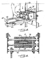
- FIGS. 7A, 7B, and 8 An alternative infeed gate assembly is depicted in FIGS. 7A, 7B, and 8 .
- the infeed gate assembly includes an infeed gate 240 pivotally connected at its upper edge to a member 241 of the structure that includes the upper web support plate 74 .
- An actuator 242 such as a pneumatic cylinder or the like is connected between the structure and the infeed gate for causing pivotal movement of the gate between a first or blocking position shown in FIG. 7A and a second or unblocking position shown in FIG. 7B .
- the infeed gate can be positioned at different angular orientations for products of different heights so that a fin length (i.e., the length of packaging material that extends forward of the leading edge of the product on a finished package) can be varied as desired.
- the fin length will vary for different height products.
- the thicker or higher product P will have a greater fin length than the thinner product because the leading edge of the thicker product will be located farther upstream from the package cutoff device (not shown) compared to the thinner product.
- a sensor 244 can be located downstream of the gate for detecting the product as it is conveyed past the gate.
- the gate can include a slot 246 at its lower edge to prevent blocking the sensor's light of sight when the gate is raised as shown in FIG. 7B .
- the sensor signal can be used for various purposes. For example, once the product clears the sensor location, the gate can be lowered again in preparation for the next product.
- the infeed gate assembly includes an infeed gate 340 that is mounted to the structure that includes the upper web support plate 74 .
- the structure defines guide tracks 348 along each of the opposite side edges of the gate, the tracks extending in an inclined direction upwardly and downstream.
- An actuator 342 is connected between the structure and the gate for moving the gate between a lowered or blocking position ( FIG. 9A ) and a raised or unblocking position ( FIG. 9B ).
- the advantage of this infeed gate assembly is that as the gate is raised, it is also moved downstream away from the product. There is thus a substantially reduced chance that the gate will tend to lift the product along with the gate and thereby inadvertently shift the product's position on the lower web.
- FIG. 10 is a diagrammatic illustration looking down on the lower web 24 on the infeed bed of the machine.
- a detector system 180 can be used to guide an operator in placing a product P on the lower web in the proper location with respect to the downstream nip rollers so that the label affixed to the upper web and the product are correctly located with respect to each other.
- the detector system can comprise various types and arrangements of detectors operable to detect the leading edge of the product.
- the illustrated detector system comprises a pair of beam emitters 182a and 184a located adjacent one longitudinal edge of the lower web 24 and spaced a slight distance apart in the longitudinal direction, and a corresponding pair of beam receivers 182b and 184b located adjacent the opposite longitudinal edge of the web directly across from the emitters.
- the emitter 182a emits a beam of light in the invisible or visible spectrum, and as long as there is no product on the web blocking the beam's path, the receiver 182b receives the beam and produces a signal.
- the receiver 184b receives the beam emitted by the emitter 184a as long as the product is not blocking the beam and produces a signal.
- the product's leading edge block the beam of the first emitter 182a but does not block the beam of the second emitter 184a ; this causes the first receiver 182b to produce no signal (or a signal of a different character), while the second receiver 184b produces a signal (or a signal of unchanged character).
- this condition it is known that the product's leading edge is in the correct location. If the product is too far downstream and blocks both beams, or is too far upstream and blocks neither beam, it is known based on the receiver signals that the product location is incorrect.
- the tolerance on leading edge location is a function of the longitudinal spacing of the emitters/receivers, and can be selected as desired.
- a "go" or “ready” light 186 connected to the detector system is illuminated only when the product is correctly located. When the operator gets the "go” light, the product length can be detected as previously described, and the packaging sequence can proceed.
- the detected product length is used in order to center a label on a package.
- the label applicator 120 tamps the label onto the upper web 22 while the upper web is being advanced toward the nip (i.e., "on-the-fly" tamping).
- the timing of the tamping is controlled by the controller 160, based on the product length, so that the label is substantially centered on the resulting package in the longitudinal direction.
- the objective is to have the longitudinal midpoint of the label and the longitudinal midpoint of the product substantially coincide in the longitudinal direction.
Landscapes
- Engineering & Computer Science (AREA)
- Mechanical Engineering (AREA)
- Labeling Devices (AREA)
- Basic Packing Technique (AREA)
- Auxiliary Devices For And Details Of Packaging Control (AREA)
- Container Filling Or Packaging Operations (AREA)
- Containers And Plastic Fillers For Packaging (AREA)
Claims (3)
- Dispositif pour emballer des produits (P) comprenant :une paire de rouleaux opposés (70, 72) formant une ligne de contact entre eux ;un système de guidage de bandes pour guider une paire de bandes supérieure et inférieure opposées (22, 24) de matériau d'emballage souple pour les faire entrer dans la ligne de contact, de sorte qu'un produit (P) à emballer, lorsqu'il est placé entre les bandes (22, 24), passe à travers la ligne de contact en même temps que les bandes (22, 24), les surfaces en regard des bandes (22, 24) comportant un matériau de scellement pour sceller les bandes entre elles en enfermant le produit ; etun alimenteur (40) situé en amont de la ligne de contact, la bande inférieure (24) étant supportée par l'alimenteur (40) de telle manière qu'un produit (P) à emballer peut être placé sur la bande inférieure (24) présente sur l'alimenteur (40) et peut avancer en même temps que la bande inférieure (24) dans une direction longitudinale qui l'introduit dans la ligne de contact ; et caractérisé par :un élément de support d'étiquetage généralement plan (74) espacé en amont de la ligne de contact ;dans lequel le système de guidage de bandes comprend des guides de bande supérieure (78, 80) conçus et agencés pour guider la bande supérieure (22) pour qu'elle se déplace le long d'une surface supérieure de l'élément de support d'étiquetage (74) de manière telle que la bande supérieure (22) est supportée par l'élément de support d'étiquetage (74) et une surface supérieure de la bande supérieure (22) est accessible pour y fixer une étiquette adhésive.
- Dispositif selon la revendication 1, l'alimenteur (40) supportant des guides de bords de bande qui se mettent en contact avec les bords opposés de la bande inférieure (24) et empêchent substantiellement le déplacement de la bande inférieure (24) sauf dans la direction longitudinale.
- Dispositif selon la revendication 1 ou 2, dans lequel l'élément de support d'étiquetage comprend une plaque de support supérieure généralement horizontale (4) ayant des bords longitudinaux opposés, et une paire de plaques latérales généralement verticales et s'étendant longitudinalement (76) reliées à et descendant depuis les bords longitudinaux opposés de la plaque de support supérieure (74) afin de former un enclos partiel disposé sur l' alimenteur (40).
Applications Claiming Priority (3)
| Application Number | Priority Date | Filing Date | Title |
|---|---|---|---|
| US11/093,365 US7386968B2 (en) | 2005-03-30 | 2005-03-30 | Packaging machine and method |
| EP08005521A EP1932764B1 (fr) | 2005-03-30 | 2006-03-29 | Machine et procédé de conditionnement |
| EP06251737A EP1707490B1 (fr) | 2005-03-30 | 2006-03-29 | Machine d'emballage et procédé |
Related Parent Applications (2)
| Application Number | Title | Priority Date | Filing Date |
|---|---|---|---|
| EP06251737.0 Division | 2006-03-29 | ||
| EP08005521.3 Division | 2008-03-25 |
Publications (2)
| Publication Number | Publication Date |
|---|---|
| EP2199213A1 EP2199213A1 (fr) | 2010-06-23 |
| EP2199213B1 true EP2199213B1 (fr) | 2011-10-12 |
Family
ID=36499431
Family Applications (4)
| Application Number | Title | Priority Date | Filing Date |
|---|---|---|---|
| EP10001873A Active EP2199213B1 (fr) | 2005-03-30 | 2006-03-29 | Machine et procédé de conditionnement |
| EP06251737A Active EP1707490B1 (fr) | 2005-03-30 | 2006-03-29 | Machine d'emballage et procédé |
| EP10001872A Active EP2199212B1 (fr) | 2005-03-30 | 2006-03-29 | Machine et procédé de conditionnement |
| EP08005521A Active EP1932764B1 (fr) | 2005-03-30 | 2006-03-29 | Machine et procédé de conditionnement |
Family Applications After (3)
| Application Number | Title | Priority Date | Filing Date |
|---|---|---|---|
| EP06251737A Active EP1707490B1 (fr) | 2005-03-30 | 2006-03-29 | Machine d'emballage et procédé |
| EP10001872A Active EP2199212B1 (fr) | 2005-03-30 | 2006-03-29 | Machine et procédé de conditionnement |
| EP08005521A Active EP1932764B1 (fr) | 2005-03-30 | 2006-03-29 | Machine et procédé de conditionnement |
Country Status (7)
| Country | Link |
|---|---|
| US (3) | US7386968B2 (fr) |
| EP (4) | EP2199213B1 (fr) |
| AT (4) | ATE528217T1 (fr) |
| BR (1) | BRPI0601094B1 (fr) |
| CA (2) | CA2634707A1 (fr) |
| DE (2) | DE602006001674D1 (fr) |
| ES (4) | ES2343705T3 (fr) |
Families Citing this family (63)
| Publication number | Priority date | Publication date | Assignee | Title |
|---|---|---|---|---|
| US7568327B2 (en) | 2003-01-31 | 2009-08-04 | Lantech.Com, Llc | Method and apparatus for securing a load to a pallet with a roped film web |
| DE102004020578B4 (de) * | 2004-04-27 | 2006-12-21 | Siemens Ag | Maschine mit Stützelementen |
| US7707801B2 (en) | 2005-04-08 | 2010-05-04 | Lantech.Com, Llc | Method for dispensing a predetermined amount of film relative to load girth |
| ITMI20060303A1 (it) | 2006-02-20 | 2007-08-21 | Colibri System Spa | Macchina per ricoprire articoli di vario tipo |
| CA2834158C (fr) * | 2006-02-23 | 2016-04-26 | Lantech.Com, Llc | Procede et appareil de distribution dosee de film pre-etire |
| US20080096748A1 (en) * | 2006-10-23 | 2008-04-24 | Antonevich Donald F | Reusable package, apparatus, and method |
| EP2088082B1 (fr) * | 2006-10-25 | 2012-12-05 | ISHIDA CO., Ltd. | Appareil de conditionnement en chapelet, et dispositif de préhension et dispositif de dépliement destiné à être utilisé dans l'appareil |
| US7748199B2 (en) * | 2006-11-28 | 2010-07-06 | Align Technology, Inc. | System and method for packaging of mass-fabricated custom items |
| KR100905216B1 (ko) | 2007-12-14 | 2009-07-01 | 안용우 | 전자식 저울이 구비된 랩 포장기 |
| US9908648B2 (en) * | 2008-01-07 | 2018-03-06 | Lantech.Com, Llc | Demand based wrapping |
| EP3375718A1 (fr) * | 2008-01-07 | 2018-09-19 | Lantech.Com LLC | Commande électronique de distribution de film dosée dans un appareil d'emballage |
| US8370270B2 (en) * | 2008-02-11 | 2013-02-05 | Xerox Corporation | System and method for creating an efficient shipping strategy for shipping printed material |
| WO2009105879A1 (fr) * | 2008-02-29 | 2009-09-03 | 9192-9281 Quebec Inc. | Appareil pour emballer un article et procédé associé |
| US8770626B2 (en) * | 2009-04-13 | 2014-07-08 | Numina Group, Incorporated | Method and apparatus for superposed application of shipping labels over packing slips |
| US20100282026A1 (en) * | 2009-05-11 | 2010-11-11 | Baker Hughes Incorporated | Method and system for automated earth boring drill bit manufacturing |
| US8517079B2 (en) | 2010-01-29 | 2013-08-27 | Bosch Packaging Technology, Inc. | Sealing apparatus |
| US9623622B2 (en) | 2010-02-24 | 2017-04-18 | Michael Baines | Packaging materials and methods |
| US8359816B2 (en) * | 2010-05-25 | 2013-01-29 | Juno Technologies, Llc | Apparatus for and method of shipping a child-resistant medicate container |
| JP5605085B2 (ja) * | 2010-08-27 | 2014-10-15 | 株式会社寺岡精工 | ヒートシール包装装置 |
| US8534524B2 (en) | 2010-10-08 | 2013-09-17 | Gtech Corporation | Perforated ticket dispensing machine |
| US9488557B2 (en) | 2010-10-29 | 2016-11-08 | Lantech.Com, Llc | Machine generated wrap data |
| EP2632804B1 (fr) * | 2010-10-29 | 2016-06-01 | Lantech.Com LLC | Données d'enveloppement générées par une machine |
| US9156575B2 (en) * | 2011-01-21 | 2015-10-13 | Signode Industrial Grop LLC | Bagging, sealing, and labeling system and method |
| CN102582859B (zh) * | 2012-02-26 | 2015-02-04 | 江苏保力自动化科技有限公司 | 一种涉及气动式钱把码垛捆扎贴标一体机 |
| ITVI20120078A1 (it) * | 2012-04-03 | 2013-10-04 | Easy Access Internat Co Limi Ted | Telaio di supporto per macchinario industriale |
| US10005581B2 (en) | 2012-10-25 | 2018-06-26 | Lantech.Com, Llc | Effective circumference-based wrapping |
| AU2013334172B2 (en) | 2012-10-25 | 2017-09-14 | Lantech.Com, Llc | Corner geometry-based wrapping |
| AU2013334151B2 (en) | 2012-10-25 | 2017-09-14 | Lantech.Com, Llc | Rotation angle-based wrapping |
| USD690199S1 (en) | 2012-10-25 | 2013-09-24 | Juno Technologies, Llc | Medicate container |
| DE102012112680B4 (de) * | 2012-12-19 | 2016-09-22 | Gerhard Schwucht | Verfahren und Vorrichtung zum Umreifen eines Packgutes mit Etikettierung |
| EP2956368B1 (fr) | 2013-02-13 | 2018-12-26 | Lantech.Com LLC | Profilage de matériau d'emballage pour emballage de confinement basé sur la force |
| US9919825B2 (en) * | 2013-08-28 | 2018-03-20 | Odds, Llc | System and method for packaging a food product |
| US9896229B1 (en) | 2013-08-29 | 2018-02-20 | Top Tier, Llc | Stretch wrapping apparatus and method |
| US9655303B2 (en) | 2013-09-17 | 2017-05-23 | Signode Industrial Group Llc | Method for containing a bale of compressible material |
| EP3521183B1 (fr) | 2014-01-14 | 2021-05-19 | Lantech.com, LLC | Réglage dynamique du paramètre de force d'enveloppement en réponse à la force d'enveloppement contrôlée et/ou la réduction des ruptures de film |
| USD766347S1 (en) * | 2014-04-29 | 2016-09-13 | Chandra Maurya Pte Ltd | Napkin roller machine |
| DE102014208165A1 (de) * | 2014-04-30 | 2015-11-05 | Kallfass Verpackungsmaschinen Gmbh | Verfahren und Vorrichtung zum Verpacken |
| US10160177B2 (en) * | 2014-06-27 | 2018-12-25 | Pregis Intellipack Llc | Protective packaging device queue control |
| EP3204301B1 (fr) | 2014-10-07 | 2020-03-11 | Lantech.Com LLC | Enveloppage basé sur la stabilité d'une charge |
| US11572206B2 (en) | 2015-05-05 | 2023-02-07 | Sealed Air Corporation (Us) | Packaging system |
| WO2019055188A1 (fr) * | 2017-09-15 | 2019-03-21 | Sealed Air Corporation (Us) | Suivi d'objets dans des systèmes d'emballage |
| US10206333B2 (en) | 2015-05-14 | 2019-02-19 | Signode Industrial Group Llc | Compressed bale packaging apparatus with bag applicator assist device and bag for same |
| KR101779326B1 (ko) | 2015-05-27 | 2017-09-27 | 티에스케이 주식회사 | 토출라인 형성이 용이한 파우치 제조장치 |
| CA2999861C (fr) | 2015-09-25 | 2020-05-05 | Lantech.Com, Llc | Machine d'emballage par etirage avec determination automatique de stabilite de charge par le fait de soumettre une charge a une perturbation |
| CN107651230A (zh) * | 2016-07-25 | 2018-02-02 | 杨辰 | 医用采血管打包装置 |
| WO2018039385A1 (fr) | 2016-08-23 | 2018-03-01 | Automated Solotions, Llc | Systèmes de formation d'emballages et procédés associés |
| MX2019003471A (es) * | 2016-09-27 | 2019-06-03 | Rxsafe Llc | Sistema para empacar productos farmaceuticos. |
| US10745227B1 (en) * | 2016-10-28 | 2020-08-18 | Quality Packaging Corp. | Packaging apparatus |
| US20180118397A1 (en) * | 2016-10-28 | 2018-05-03 | Illinois Tool Works Inc. | Wrapping machine printer arrangement and wrapping machine film cutter arrangement |
| EP3642130B1 (fr) * | 2017-06-19 | 2021-12-22 | Sealed Air Corporation (US) | Procédé et systemes de formation d'un emballage embourré et emballage rembourré obtenu pour la protection d'objets |
| AU2018338049B2 (en) | 2017-09-22 | 2021-12-23 | Lantech.Com, Llc | Load wrapping apparatus wrap profiles with controlled wrap cycle interruptions |
| GB2569944A (en) * | 2017-12-23 | 2019-07-10 | Vancebuild Ltd | A packaging machine |
| US10773504B2 (en) * | 2018-06-22 | 2020-09-15 | Apple Inc. | Systems and methods for manufacturing battery cells |
| CA3106566C (fr) | 2018-08-06 | 2023-04-04 | Lantech.Com, Llc | Emballeuse sous film etirable avec controle de debit de distribution par ajustement de courbe |
| US10706239B1 (en) * | 2018-12-14 | 2020-07-07 | Amazon Technologies, Inc. | Integrated label printer and barcode reader, and related systems and methods |
| USD916938S1 (en) * | 2019-03-26 | 2021-04-20 | Panotec S.R.L. | Packing machine |
| CN109969472B (zh) * | 2019-04-28 | 2024-06-21 | 苏州蓝智特种机器人有限公司 | 一种自动边封贴标生产线 |
| AU2020346736B2 (en) | 2019-09-09 | 2024-02-22 | Lantech.Com, Llc | Stretch wrapping machine with dispense rate control based on sensed rate of dispensed packaging material and predicted load geometry |
| WO2021055193A1 (fr) | 2019-09-19 | 2021-03-25 | Lantech.Com, Llc | Classement de matériaux d'emballage et/ou profils d'usine |
| US20220111986A1 (en) * | 2020-10-09 | 2022-04-14 | Westrock Shared Services, Llc | Systems and methods for packaging stacked products |
| CN113479408B (zh) * | 2021-05-28 | 2023-01-31 | 深圳市智信精密仪器股份有限公司 | 一种高速手机彩盒自动包装线及智能包装方法 |
| CN113665933B (zh) * | 2021-08-20 | 2023-04-11 | 广东工业大学 | 一种称重打印包装系统及其控制方法 |
| CN113978823A (zh) * | 2021-11-15 | 2022-01-28 | 徐州金虹钢铁集团有限公司 | 一种工字盘包装流水线 |
Family Cites Families (76)
| Publication number | Priority date | Publication date | Assignee | Title |
|---|---|---|---|---|
| GB1053915A (fr) | 1900-01-01 | |||
| US2083618A (en) * | 1935-10-15 | 1937-06-15 | Ivers Lee Co | Packaging apparatus |
| US2309621A (en) | 1938-07-02 | 1943-02-02 | Millie Patent Holding Co Inc | Packaging apparatus and method |
| US2340260A (en) | 1940-07-12 | 1944-01-25 | Wingfoot Corp | Packaging eggs and the like |
| US2597041A (en) * | 1947-03-27 | 1952-05-20 | Stokes & Smith Co | Apparatus for wrapping articles |
| US2597042A (en) | 1947-04-07 | 1952-05-20 | Stokes & Smith Co | Two-web rotary brush wrapping machine |
| US2525651A (en) | 1948-07-02 | 1950-10-10 | Wingfoot Corp | Packaging |
| US2639567A (en) | 1950-03-13 | 1953-05-26 | John P Murdoch | Universal packaging machine |
| US2737764A (en) * | 1953-01-30 | 1956-03-13 | Lewis J Clyde | Method and apparatus for packaging articles |
| US2914896A (en) * | 1959-03-18 | 1959-12-01 | Republic Aviat Corp | Device for packaging machines |
| US3189702A (en) * | 1962-08-15 | 1965-06-15 | Minnesota Mining & Mfg | Package and method of making |
| US3289386A (en) * | 1963-03-01 | 1966-12-06 | Reynolds Metals Co | Method of making labeled package |
| US3453169A (en) | 1965-10-23 | 1969-07-01 | N R Buck Co Inc | Encapsulator |
| US3503175A (en) * | 1966-11-28 | 1970-03-31 | American Mach & Foundry | Bulk packer |
| GB1206163A (en) | 1967-02-21 | 1970-09-23 | Aspro Nicholas Ltd | Improvements relating to blister packs. |
| US3579957A (en) * | 1967-03-03 | 1971-05-25 | Amf Inc | Bagging apparatus |
| US3432981A (en) | 1967-05-15 | 1969-03-18 | Menschner Textil Johannes | Method of and apparatus for packing,preferably of textile laps or bales in double plastic films |
| US3432988A (en) | 1967-05-15 | 1969-03-18 | Menschner Textil Johannes | Apparatus for packing,preferably of round or flat laps or bales in plastic film packings |
| US3552088A (en) | 1968-07-18 | 1971-01-05 | Nishimura Seisakusho Co | Method of and apparatus for packing articles |
| GB1277725A (en) * | 1969-11-18 | 1972-06-14 | Berkel Patent Nv | A data dispensing device |
| US3650773A (en) * | 1970-02-09 | 1972-03-21 | Schreiber Cheese Co L D | Weighing and labeling system |
| SE357175B (fr) * | 1970-12-07 | 1973-06-18 | J Nordqvist | |
| US3991540A (en) | 1971-06-03 | 1976-11-16 | Situmo Holding S.A. | Packaging machine |
| US3783577A (en) * | 1971-06-24 | 1974-01-08 | Armour & Co | System for packing food patties |
| USRE29362E (en) * | 1974-01-23 | 1977-08-23 | Anderson Bros. Mfg. Co. | Packaging apparatus |
| US4030662A (en) | 1975-05-14 | 1977-06-21 | Gess Larry C | Package and method and apparatus for producing same |
| US4041674A (en) * | 1976-01-26 | 1977-08-16 | Anderson Bros. Mfg. Co. | Apparatus for packing articles, such as bottles |
| US4124694A (en) * | 1976-08-05 | 1978-11-07 | University Of Southern California | Process for the oxidation of hydrogen sulfide to sulfur trioxide |
| US4085560A (en) | 1976-10-27 | 1978-04-25 | Wrap-Ade Machine Company, Inc. | Apparatus and method of forming covers for flexible commodity-containing packages |
| US4074505A (en) | 1977-01-03 | 1978-02-21 | Sealed Air Corporation | Method and apparatus for packaging articles |
| US4244158A (en) * | 1979-03-13 | 1981-01-13 | R. Nelham & Associates Incorporated | Package forming method and apparatus |
| US4268344A (en) * | 1979-08-20 | 1981-05-19 | Glopak Industries Limited | Method and apparatus for coupon insertion |
| US4319443A (en) | 1979-09-28 | 1982-03-16 | Nordson Corporation | Film wrapping machine |
| SE446226B (sv) * | 1980-02-26 | 1986-08-18 | Teraoka Seikosho Kk | Anordning for att meta vikt, berekna pris och utfora forpackning |
| US4601157A (en) | 1984-03-15 | 1986-07-22 | The Crowell Corporation | Automatic packaging |
| US4458470A (en) | 1981-03-19 | 1984-07-10 | Weldotron Corporation | Integrated stretch-wrap packaging system |
| US4548024A (en) * | 1981-03-19 | 1985-10-22 | Weldotron Corporation | Integrated stretch-wrap packaging system |
| US5057169A (en) | 1981-03-23 | 1991-10-15 | The Crowell Corporation | Process of protecting a surface using a foam laminate |
| US4369613A (en) | 1981-03-26 | 1983-01-25 | Gess Larry C | Apparatus for producing packages of two webs of varying lengths and widths |
| US4466228A (en) | 1981-11-12 | 1984-08-21 | L. C. Gess, Inc. | Method and apparatus for producing packages from cohesive-coated media |
| US4505092A (en) * | 1982-04-26 | 1985-03-19 | Hobart Corporation | Package sensing/film control system for film wrapping machine |
| ES2017634B3 (es) * | 1985-12-24 | 1991-03-01 | Omnitech (Europe) Ltd | Maquina envasadora de introduccion horizontal |
| US4684025A (en) | 1986-01-30 | 1987-08-04 | The Procter & Gamble Company | Shaped thermoformed flexible film container for granular products and method and apparatus for making the same |
| US4705588A (en) | 1986-07-21 | 1987-11-10 | Hobart Corporation | Method and apparatus for package labeling |
| FR2619549B3 (fr) * | 1987-08-18 | 1990-01-26 | Bene Madinox | Machine pour l'enveloppement sous pellicule de produits cylindriques |
| NL8702435A (nl) | 1987-10-06 | 1989-05-01 | Stork Pmt | Werkwijze en inrichting voor het verpakken van een voorwerp. |
| FR2625971B1 (fr) * | 1988-01-14 | 1990-05-25 | Suisses France 3 | Machine d'emballage automatique d'articles quelconques et emballage realise a l'aide de cette machine |
| IT1216487B (it) | 1988-03-01 | 1990-03-08 | Sitma | Macchina per l'imballaggio con dispositivo di saldatura e taglio perfezionato. |
| FR2641518B1 (fr) * | 1989-01-12 | 1991-07-05 | Socoplan | Procede et dispositif pour la realisation de sachets en forme et contenant des doses unitaires de produits |
| GB2253385A (en) * | 1990-03-13 | 1992-09-09 | Osaka Sealing Label Print | A packaging machine incorporating a labelling device |
| US5117610A (en) * | 1990-09-21 | 1992-06-02 | Dittler Brothers, Incorporated | Methods and apparatus for printing and collating materials from multiple webs |
| DE4041743A1 (de) * | 1990-12-24 | 1992-06-25 | Schickedanz Ver Papierwerk | Kontinuierliches verfahren zum herstellen wiederverschliessbarer folienverpackungen |
| SE468387B (sv) | 1991-05-21 | 1993-01-11 | Nybo Seal System Ab | Svetsbacks-arrangemang med uppvaermningstraad foer foerslutning av foeremaal mellan tvaa materialbanor |
| US5165221A (en) | 1991-07-02 | 1992-11-24 | Great Lakes Corporation | Adjustable film forming apparatus |
| US5251988A (en) * | 1991-10-22 | 1993-10-12 | Burford Corporation | In-line printer for packaging process |
| US5269122A (en) | 1991-12-26 | 1993-12-14 | Sealed Air Corporation | Apparatus and method for forming protective packages |
| US5165122A (en) * | 1992-02-18 | 1992-11-24 | Phalen Paul J | Body transfer mat having opposing selectively engageable wing portions for securing a patient |
| WO1994006689A1 (fr) | 1992-09-21 | 1994-03-31 | Anthony James Murray Garwood | Conditionnement et etiquetage de produits destines a etre exposes |
| US5369937A (en) * | 1993-05-10 | 1994-12-06 | Joule' Inc. | Continuous casting and packaging |
| US5444964A (en) | 1993-06-22 | 1995-08-29 | Hanagata Corporation | Automatic package machine, and wrapping film fusing and sealing blade |
| EP0631936A1 (fr) | 1993-06-30 | 1995-01-04 | Rafael Gorgojo Marcus | Procédé pour mettre sous enveloppe de produits liquides, machines pour la mise en oeuvre du procédé, et emballage obtenu |
| US5443150A (en) * | 1993-09-23 | 1995-08-22 | Rapidpak, Inc. | Apparatus for advancing preformed containers |
| US5419425A (en) * | 1993-10-21 | 1995-05-30 | Goater; George H. | Apparatus and method for loading lumber onto a high-speed lugged transfer deck |
| JP2801530B2 (ja) * | 1994-08-17 | 1998-09-21 | 株式会社フジキカイ | 横型製袋充填包装機及びその制御方法 |
| US5704481A (en) | 1994-11-18 | 1998-01-06 | Ivex Corporation | Easy open package |
| CN1207724C (zh) * | 1996-06-14 | 2005-06-22 | R·布鲁克斯联合公司 | 探测装置 |
| US5956931A (en) | 1996-11-13 | 1999-09-28 | Stork Fabricators, Inc. | Apparatus for wrapping products |
| NL1006482C2 (nl) | 1997-07-04 | 1999-01-25 | Gideon Noordenbos | Inrichting voor het hygiënisch verpakken van gebruikte voorwerpen. |
| US5966908A (en) | 1998-02-20 | 1999-10-19 | Food Machinery Sales, Inc. | Article packaging machine and method of preventing the formation of defective packages |
| JP2000142634A (ja) * | 1998-11-09 | 2000-05-23 | Toumei Engineering:Kk | 簡易荷送シール装置 |
| US6209708B1 (en) * | 1999-08-04 | 2001-04-03 | Timothy L. Philipp | Conveyor system for receiving, orienting and conveying pouches |
| EP1090543A1 (fr) * | 1999-10-05 | 2001-04-11 | Lely Research Holding AG | Dispositif et procédé pour envelopper des corps, en particulier des balles de récolte |
| US20030046905A1 (en) * | 2001-09-12 | 2003-03-13 | Klaus Kaechele | Method and device for packaging objects in a weldable film |
| US6895732B2 (en) | 2002-09-09 | 2005-05-24 | Sealed Air Corporation (Us) | Packaging apparatus and method |
| GB2403198A (en) | 2003-06-27 | 2004-12-29 | Sig Technology Ltd | Utilising sensed parameters in form-fill-seal packaging |
| US7331153B1 (en) * | 2006-08-31 | 2008-02-19 | Sealed Air Corporation (Us) | Apparatus and method for creating easy to open packages |
-
2005
- 2005-03-30 US US11/093,365 patent/US7386968B2/en active Active
-
2006
- 2006-03-28 CA CA002634707A patent/CA2634707A1/fr not_active Abandoned
- 2006-03-28 CA CA002541029A patent/CA2541029C/fr not_active Expired - Fee Related
- 2006-03-29 EP EP10001873A patent/EP2199213B1/fr active Active
- 2006-03-29 ES ES08005521T patent/ES2343705T3/es active Active
- 2006-03-29 ES ES10001872T patent/ES2374213T3/es active Active
- 2006-03-29 ES ES10001873T patent/ES2372514T3/es active Active
- 2006-03-29 AT AT10001873T patent/ATE528217T1/de not_active IP Right Cessation
- 2006-03-29 AT AT10001872T patent/ATE530447T1/de not_active IP Right Cessation
- 2006-03-29 DE DE602006001674T patent/DE602006001674D1/de active Active
- 2006-03-29 EP EP06251737A patent/EP1707490B1/fr active Active
- 2006-03-29 DE DE602006014288T patent/DE602006014288D1/de active Active
- 2006-03-29 AT AT06251737T patent/ATE400501T1/de not_active IP Right Cessation
- 2006-03-29 EP EP10001872A patent/EP2199212B1/fr active Active
- 2006-03-29 ES ES06251737T patent/ES2308685T3/es active Active
- 2006-03-29 EP EP08005521A patent/EP1932764B1/fr active Active
- 2006-03-29 AT AT08005521T patent/ATE467563T1/de not_active IP Right Cessation
- 2006-03-30 BR BRPI0601094-6A patent/BRPI0601094B1/pt active IP Right Grant
-
2008
- 2008-05-21 US US12/124,226 patent/US7886502B2/en active Active
-
2011
- 2011-01-14 US US13/006,890 patent/US8033081B2/en active Active
Also Published As
| Publication number | Publication date |
|---|---|
| EP2199213A1 (fr) | 2010-06-23 |
| DE602006001674D1 (de) | 2008-08-21 |
| ES2308685T3 (es) | 2008-12-01 |
| CA2541029A1 (fr) | 2006-09-30 |
| EP2199212A1 (fr) | 2010-06-23 |
| EP1932764B1 (fr) | 2010-05-12 |
| US20060218881A1 (en) | 2006-10-05 |
| ATE528217T1 (de) | 2011-10-15 |
| EP1932764A3 (fr) | 2008-10-29 |
| ES2372514T3 (es) | 2012-01-23 |
| ATE400501T1 (de) | 2008-07-15 |
| US20090126319A1 (en) | 2009-05-21 |
| DE602006014288D1 (de) | 2010-06-24 |
| ATE467563T1 (de) | 2010-05-15 |
| US7386968B2 (en) | 2008-06-17 |
| EP1707490B1 (fr) | 2008-07-09 |
| US7886502B2 (en) | 2011-02-15 |
| EP2199212B1 (fr) | 2011-10-26 |
| BRPI0601094A (pt) | 2006-12-05 |
| CA2541029C (fr) | 2008-10-14 |
| US8033081B2 (en) | 2011-10-11 |
| ES2374213T3 (es) | 2012-02-14 |
| EP1707490A2 (fr) | 2006-10-04 |
| CA2634707A1 (fr) | 2006-09-30 |
| ES2343705T3 (es) | 2010-08-06 |
| EP1932764A2 (fr) | 2008-06-18 |
| BRPI0601094B1 (pt) | 2018-04-10 |
| EP1707490A3 (fr) | 2006-11-08 |
| US20110107725A1 (en) | 2011-05-12 |
| ATE530447T1 (de) | 2011-11-15 |
Similar Documents
| Publication | Publication Date | Title |
|---|---|---|
| EP2199213B1 (fr) | Machine et procédé de conditionnement | |
| US4415048A (en) | Weight measuring, price computing and packing apparatus | |
| KR100195874B1 (ko) | 가동 라벨 인쇄기-도포기/컨베이어 로더장치 | |
| US7765776B1 (en) | Systems and methods for dispensing pharmaceutical/medical product and branding pharmaceutical/medical containers | |
| US5757389A (en) | Printing device for objects, which are continously moved forward, in particular for parcels, wrapped magazine piles or the like | |
| EP1914169B1 (fr) | Unité et procédé pour alimenter des étiquettes dans une empaqueteuse pour produits du tabac | |
| CN102239095A (zh) | 板状件加工机的校准方法 | |
| EP3947164B1 (fr) | Appareil et procede de banderolage de paquets | |
| US4578926A (en) | Apparatus for packaging, weighing and labeling merchandise | |
| CN109515010B (zh) | 半导体封测用全自动激光打标系统打标定位机构 | |
| JP2958180B2 (ja) | 高圧ガス充填方法 | |
| US4705588A (en) | Method and apparatus for package labeling | |
| JP2842373B2 (ja) | ラベル貼付装置 | |
| JP2842372B2 (ja) | 包装値付装置 | |
| JPH03124523A (ja) | 箱詰装置 | |
| JPH0134850B2 (fr) | ||
| KR102625355B1 (ko) | 박스의 위치이동 기능을 가지는 밴딩기 | |
| JP4517171B2 (ja) | 積層体の構成物へのラベル貼付装置及びラベル貼付方法 | |
| GB2403198A (en) | Utilising sensed parameters in form-fill-seal packaging | |
| JP2004026313A (ja) | 包装値付装置 | |
| JPH076105U (ja) | ストレッチ包装機 | |
| GB2496053A (en) | Plank testing apparatus | |
| ITMI950851A1 (it) | Metodo ed apparecchiatura per palletizzare pacchi con dispositivo di accompagnamento superiore | |
| JPH01196384A (ja) | インクモジュール | |
| JPH1086909A (ja) | 包装箱封緘装置 |
Legal Events
| Date | Code | Title | Description |
|---|---|---|---|
| PUAI | Public reference made under article 153(3) epc to a published international application that has entered the european phase |
Free format text: ORIGINAL CODE: 0009012 |
|
| AC | Divisional application: reference to earlier application |
Ref document number: 1707490 Country of ref document: EP Kind code of ref document: P Ref document number: 1932764 Country of ref document: EP Kind code of ref document: P |
|
| AK | Designated contracting states |
Kind code of ref document: A1 Designated state(s): AT BE BG CH CY CZ DE DK EE ES FI FR GB GR HU IE IS IT LI LT LU LV MC NL PL PT RO SE SI SK TR |
|
| AX | Request for extension of the european patent |
Extension state: AL BA HR MK YU |
|
| 17P | Request for examination filed |
Effective date: 20100809 |
|
| GRAP | Despatch of communication of intention to grant a patent |
Free format text: ORIGINAL CODE: EPIDOSNIGR1 |
|
| RIC1 | Information provided on ipc code assigned before grant |
Ipc: B65B 59/02 20060101ALI20110408BHEP Ipc: B65C 1/02 20060101ALI20110408BHEP Ipc: B65G 47/88 20060101ALI20110408BHEP Ipc: B65B 35/10 20060101ALI20110408BHEP Ipc: B65B 9/02 20060101AFI20110408BHEP |
|
| GRAS | Grant fee paid |
Free format text: ORIGINAL CODE: EPIDOSNIGR3 |
|
| GRAA | (expected) grant |
Free format text: ORIGINAL CODE: 0009210 |
|
| AC | Divisional application: reference to earlier application |
Ref document number: 1932764 Country of ref document: EP Kind code of ref document: P Ref document number: 1707490 Country of ref document: EP Kind code of ref document: P |
|
| AK | Designated contracting states |
Kind code of ref document: B1 Designated state(s): AT BE BG CH CY CZ DE DK EE ES FI FR GB GR HU IE IS IT LI LT LU LV MC NL PL PT RO SE SI SK TR |
|
| REG | Reference to a national code |
Ref country code: GB Ref legal event code: FG4D |
|
| REG | Reference to a national code |
Ref country code: CH Ref legal event code: EP |
|
| REG | Reference to a national code |
Ref country code: IE Ref legal event code: FG4D |
|
| REG | Reference to a national code |
Ref country code: DE Ref legal event code: R096 Ref document number: 602006025134 Country of ref document: DE Effective date: 20111208 |
|
| REG | Reference to a national code |
Ref country code: ES Ref legal event code: FG2A Ref document number: 2372514 Country of ref document: ES Kind code of ref document: T3 Effective date: 20120123 |
|
| REG | Reference to a national code |
Ref country code: NL Ref legal event code: VDEP Effective date: 20111012 |
|
| LTIE | Lt: invalidation of european patent or patent extension |
Effective date: 20111012 |
|
| REG | Reference to a national code |
Ref country code: AT Ref legal event code: MK05 Ref document number: 528217 Country of ref document: AT Kind code of ref document: T Effective date: 20111012 |
|
| PG25 | Lapsed in a contracting state [announced via postgrant information from national office to epo] |
Ref country code: BE Free format text: LAPSE BECAUSE OF FAILURE TO SUBMIT A TRANSLATION OF THE DESCRIPTION OR TO PAY THE FEE WITHIN THE PRESCRIBED TIME-LIMIT Effective date: 20111012 Ref country code: LT Free format text: LAPSE BECAUSE OF FAILURE TO SUBMIT A TRANSLATION OF THE DESCRIPTION OR TO PAY THE FEE WITHIN THE PRESCRIBED TIME-LIMIT Effective date: 20111012 Ref country code: IS Free format text: LAPSE BECAUSE OF FAILURE TO SUBMIT A TRANSLATION OF THE DESCRIPTION OR TO PAY THE FEE WITHIN THE PRESCRIBED TIME-LIMIT Effective date: 20120212 |
|
| PG25 | Lapsed in a contracting state [announced via postgrant information from national office to epo] |
Ref country code: SE Free format text: LAPSE BECAUSE OF FAILURE TO SUBMIT A TRANSLATION OF THE DESCRIPTION OR TO PAY THE FEE WITHIN THE PRESCRIBED TIME-LIMIT Effective date: 20111012 Ref country code: SI Free format text: LAPSE BECAUSE OF FAILURE TO SUBMIT A TRANSLATION OF THE DESCRIPTION OR TO PAY THE FEE WITHIN THE PRESCRIBED TIME-LIMIT Effective date: 20111012 Ref country code: NL Free format text: LAPSE BECAUSE OF FAILURE TO SUBMIT A TRANSLATION OF THE DESCRIPTION OR TO PAY THE FEE WITHIN THE PRESCRIBED TIME-LIMIT Effective date: 20111012 Ref country code: GR Free format text: LAPSE BECAUSE OF FAILURE TO SUBMIT A TRANSLATION OF THE DESCRIPTION OR TO PAY THE FEE WITHIN THE PRESCRIBED TIME-LIMIT Effective date: 20120113 Ref country code: PT Free format text: LAPSE BECAUSE OF FAILURE TO SUBMIT A TRANSLATION OF THE DESCRIPTION OR TO PAY THE FEE WITHIN THE PRESCRIBED TIME-LIMIT Effective date: 20120213 Ref country code: LV Free format text: LAPSE BECAUSE OF FAILURE TO SUBMIT A TRANSLATION OF THE DESCRIPTION OR TO PAY THE FEE WITHIN THE PRESCRIBED TIME-LIMIT Effective date: 20111012 |
|
| PG25 | Lapsed in a contracting state [announced via postgrant information from national office to epo] |
Ref country code: CY Free format text: LAPSE BECAUSE OF FAILURE TO SUBMIT A TRANSLATION OF THE DESCRIPTION OR TO PAY THE FEE WITHIN THE PRESCRIBED TIME-LIMIT Effective date: 20111012 |
|
| PG25 | Lapsed in a contracting state [announced via postgrant information from national office to epo] |
Ref country code: EE Free format text: LAPSE BECAUSE OF FAILURE TO SUBMIT A TRANSLATION OF THE DESCRIPTION OR TO PAY THE FEE WITHIN THE PRESCRIBED TIME-LIMIT Effective date: 20111012 Ref country code: SK Free format text: LAPSE BECAUSE OF FAILURE TO SUBMIT A TRANSLATION OF THE DESCRIPTION OR TO PAY THE FEE WITHIN THE PRESCRIBED TIME-LIMIT Effective date: 20111012 Ref country code: CZ Free format text: LAPSE BECAUSE OF FAILURE TO SUBMIT A TRANSLATION OF THE DESCRIPTION OR TO PAY THE FEE WITHIN THE PRESCRIBED TIME-LIMIT Effective date: 20111012 Ref country code: BG Free format text: LAPSE BECAUSE OF FAILURE TO SUBMIT A TRANSLATION OF THE DESCRIPTION OR TO PAY THE FEE WITHIN THE PRESCRIBED TIME-LIMIT Effective date: 20120112 Ref country code: DK Free format text: LAPSE BECAUSE OF FAILURE TO SUBMIT A TRANSLATION OF THE DESCRIPTION OR TO PAY THE FEE WITHIN THE PRESCRIBED TIME-LIMIT Effective date: 20111012 |
|
| PLBE | No opposition filed within time limit |
Free format text: ORIGINAL CODE: 0009261 |
|
| STAA | Information on the status of an ep patent application or granted ep patent |
Free format text: STATUS: NO OPPOSITION FILED WITHIN TIME LIMIT |
|
| PG25 | Lapsed in a contracting state [announced via postgrant information from national office to epo] |
Ref country code: RO Free format text: LAPSE BECAUSE OF FAILURE TO SUBMIT A TRANSLATION OF THE DESCRIPTION OR TO PAY THE FEE WITHIN THE PRESCRIBED TIME-LIMIT Effective date: 20111012 Ref country code: PL Free format text: LAPSE BECAUSE OF FAILURE TO SUBMIT A TRANSLATION OF THE DESCRIPTION OR TO PAY THE FEE WITHIN THE PRESCRIBED TIME-LIMIT Effective date: 20111012 |
|
| 26N | No opposition filed |
Effective date: 20120713 |
|
| PG25 | Lapsed in a contracting state [announced via postgrant information from national office to epo] |
Ref country code: MC Free format text: LAPSE BECAUSE OF NON-PAYMENT OF DUE FEES Effective date: 20120331 |
|
| REG | Reference to a national code |
Ref country code: CH Ref legal event code: PL |
|
| REG | Reference to a national code |
Ref country code: DE Ref legal event code: R097 Ref document number: 602006025134 Country of ref document: DE Effective date: 20120713 |
|
| REG | Reference to a national code |
Ref country code: IE Ref legal event code: MM4A |
|
| PG25 | Lapsed in a contracting state [announced via postgrant information from national office to epo] |
Ref country code: LI Free format text: LAPSE BECAUSE OF NON-PAYMENT OF DUE FEES Effective date: 20120331 Ref country code: AT Free format text: LAPSE BECAUSE OF FAILURE TO SUBMIT A TRANSLATION OF THE DESCRIPTION OR TO PAY THE FEE WITHIN THE PRESCRIBED TIME-LIMIT Effective date: 20111012 Ref country code: IE Free format text: LAPSE BECAUSE OF NON-PAYMENT OF DUE FEES Effective date: 20120329 Ref country code: CH Free format text: LAPSE BECAUSE OF NON-PAYMENT OF DUE FEES Effective date: 20120331 |
|
| PG25 | Lapsed in a contracting state [announced via postgrant information from national office to epo] |
Ref country code: FI Free format text: LAPSE BECAUSE OF FAILURE TO SUBMIT A TRANSLATION OF THE DESCRIPTION OR TO PAY THE FEE WITHIN THE PRESCRIBED TIME-LIMIT Effective date: 20111012 |
|
| PG25 | Lapsed in a contracting state [announced via postgrant information from national office to epo] |
Ref country code: TR Free format text: LAPSE BECAUSE OF FAILURE TO SUBMIT A TRANSLATION OF THE DESCRIPTION OR TO PAY THE FEE WITHIN THE PRESCRIBED TIME-LIMIT Effective date: 20111012 |
|
| PG25 | Lapsed in a contracting state [announced via postgrant information from national office to epo] |
Ref country code: LU Free format text: LAPSE BECAUSE OF NON-PAYMENT OF DUE FEES Effective date: 20120329 |
|
| PG25 | Lapsed in a contracting state [announced via postgrant information from national office to epo] |
Ref country code: HU Free format text: LAPSE BECAUSE OF FAILURE TO SUBMIT A TRANSLATION OF THE DESCRIPTION OR TO PAY THE FEE WITHIN THE PRESCRIBED TIME-LIMIT Effective date: 20060329 |
|
| REG | Reference to a national code |
Ref country code: FR Ref legal event code: PLFP Year of fee payment: 11 |
|
| REG | Reference to a national code |
Ref country code: FR Ref legal event code: PLFP Year of fee payment: 12 |
|
| REG | Reference to a national code |
Ref country code: FR Ref legal event code: PLFP Year of fee payment: 13 |
|
| PGFP | Annual fee paid to national office [announced via postgrant information from national office to epo] |
Ref country code: FR Payment date: 20230327 Year of fee payment: 18 |
|
| PGFP | Annual fee paid to national office [announced via postgrant information from national office to epo] |
Ref country code: IT Payment date: 20230321 Year of fee payment: 18 Ref country code: GB Payment date: 20230327 Year of fee payment: 18 Ref country code: DE Payment date: 20230329 Year of fee payment: 18 |
|
| P01 | Opt-out of the competence of the unified patent court (upc) registered |
Effective date: 20230425 |
|
| PGFP | Annual fee paid to national office [announced via postgrant information from national office to epo] |
Ref country code: ES Payment date: 20230403 Year of fee payment: 18 |