EP2199057A1 - Structure de bobine de refroidissement/chauffage coaxial et le moule configuré avec celui-ci - Google Patents
Structure de bobine de refroidissement/chauffage coaxial et le moule configuré avec celui-ci Download PDFInfo
- Publication number
- EP2199057A1 EP2199057A1 EP09180023A EP09180023A EP2199057A1 EP 2199057 A1 EP2199057 A1 EP 2199057A1 EP 09180023 A EP09180023 A EP 09180023A EP 09180023 A EP09180023 A EP 09180023A EP 2199057 A1 EP2199057 A1 EP 2199057A1
- Authority
- EP
- European Patent Office
- Prior art keywords
- cooling
- cooling channel
- heat
- mold
- heating coil
- Prior art date
- Legal status (The legal status is an assumption and is not a legal conclusion. Google has not performed a legal analysis and makes no representation as to the accuracy of the status listed.)
- Granted
Links
Images


Classifications
-
- B—PERFORMING OPERATIONS; TRANSPORTING
- B29—WORKING OF PLASTICS; WORKING OF SUBSTANCES IN A PLASTIC STATE IN GENERAL
- B29C—SHAPING OR JOINING OF PLASTICS; SHAPING OF MATERIAL IN A PLASTIC STATE, NOT OTHERWISE PROVIDED FOR; AFTER-TREATMENT OF THE SHAPED PRODUCTS, e.g. REPAIRING
- B29C45/00—Injection moulding, i.e. forcing the required volume of moulding material through a nozzle into a closed mould; Apparatus therefor
- B29C45/17—Component parts, details or accessories; Auxiliary operations
- B29C45/72—Heating or cooling
- B29C45/73—Heating or cooling of the mould
-
- B—PERFORMING OPERATIONS; TRANSPORTING
- B29—WORKING OF PLASTICS; WORKING OF SUBSTANCES IN A PLASTIC STATE IN GENERAL
- B29C—SHAPING OR JOINING OF PLASTICS; SHAPING OF MATERIAL IN A PLASTIC STATE, NOT OTHERWISE PROVIDED FOR; AFTER-TREATMENT OF THE SHAPED PRODUCTS, e.g. REPAIRING
- B29C33/00—Moulds or cores; Details thereof or accessories therefor
- B29C33/02—Moulds or cores; Details thereof or accessories therefor with incorporated heating or cooling means
- B29C33/04—Moulds or cores; Details thereof or accessories therefor with incorporated heating or cooling means using liquids, gas or steam
-
- B—PERFORMING OPERATIONS; TRANSPORTING
- B29—WORKING OF PLASTICS; WORKING OF SUBSTANCES IN A PLASTIC STATE IN GENERAL
- B29C—SHAPING OR JOINING OF PLASTICS; SHAPING OF MATERIAL IN A PLASTIC STATE, NOT OTHERWISE PROVIDED FOR; AFTER-TREATMENT OF THE SHAPED PRODUCTS, e.g. REPAIRING
- B29C33/00—Moulds or cores; Details thereof or accessories therefor
- B29C33/02—Moulds or cores; Details thereof or accessories therefor with incorporated heating or cooling means
- B29C33/06—Moulds or cores; Details thereof or accessories therefor with incorporated heating or cooling means using radiation, e.g. electro-magnetic waves, induction heating
-
- B—PERFORMING OPERATIONS; TRANSPORTING
- B29—WORKING OF PLASTICS; WORKING OF SUBSTANCES IN A PLASTIC STATE IN GENERAL
- B29C—SHAPING OR JOINING OF PLASTICS; SHAPING OF MATERIAL IN A PLASTIC STATE, NOT OTHERWISE PROVIDED FOR; AFTER-TREATMENT OF THE SHAPED PRODUCTS, e.g. REPAIRING
- B29C35/00—Heating, cooling or curing, e.g. crosslinking or vulcanising; Apparatus therefor
- B29C35/02—Heating or curing, e.g. crosslinking or vulcanizing during moulding, e.g. in a mould
- B29C35/08—Heating or curing, e.g. crosslinking or vulcanizing during moulding, e.g. in a mould by wave energy or particle radiation
- B29C35/0805—Heating or curing, e.g. crosslinking or vulcanizing during moulding, e.g. in a mould by wave energy or particle radiation using electromagnetic radiation
-
- H—ELECTRICITY
- H05—ELECTRIC TECHNIQUES NOT OTHERWISE PROVIDED FOR
- H05B—ELECTRIC HEATING; ELECTRIC LIGHT SOURCES NOT OTHERWISE PROVIDED FOR; CIRCUIT ARRANGEMENTS FOR ELECTRIC LIGHT SOURCES, IN GENERAL
- H05B6/00—Heating by electric, magnetic or electromagnetic fields
- H05B6/02—Induction heating
- H05B6/36—Coil arrangements
- H05B6/42—Cooling of coils
-
- B—PERFORMING OPERATIONS; TRANSPORTING
- B29—WORKING OF PLASTICS; WORKING OF SUBSTANCES IN A PLASTIC STATE IN GENERAL
- B29C—SHAPING OR JOINING OF PLASTICS; SHAPING OF MATERIAL IN A PLASTIC STATE, NOT OTHERWISE PROVIDED FOR; AFTER-TREATMENT OF THE SHAPED PRODUCTS, e.g. REPAIRING
- B29C35/00—Heating, cooling or curing, e.g. crosslinking or vulcanising; Apparatus therefor
- B29C35/02—Heating or curing, e.g. crosslinking or vulcanizing during moulding, e.g. in a mould
- B29C35/08—Heating or curing, e.g. crosslinking or vulcanizing during moulding, e.g. in a mould by wave energy or particle radiation
- B29C35/0805—Heating or curing, e.g. crosslinking or vulcanizing during moulding, e.g. in a mould by wave energy or particle radiation using electromagnetic radiation
- B29C2035/0811—Heating or curing, e.g. crosslinking or vulcanizing during moulding, e.g. in a mould by wave energy or particle radiation using electromagnetic radiation using induction
- B29C2035/0816—Heating or curing, e.g. crosslinking or vulcanizing during moulding, e.g. in a mould by wave energy or particle radiation using electromagnetic radiation using induction using eddy currents
-
- B—PERFORMING OPERATIONS; TRANSPORTING
- B29—WORKING OF PLASTICS; WORKING OF SUBSTANCES IN A PLASTIC STATE IN GENERAL
- B29C—SHAPING OR JOINING OF PLASTICS; SHAPING OF MATERIAL IN A PLASTIC STATE, NOT OTHERWISE PROVIDED FOR; AFTER-TREATMENT OF THE SHAPED PRODUCTS, e.g. REPAIRING
- B29C35/00—Heating, cooling or curing, e.g. crosslinking or vulcanising; Apparatus therefor
- B29C35/16—Cooling
- B29C2035/1616—Cooling using liquids
-
- B—PERFORMING OPERATIONS; TRANSPORTING
- B29—WORKING OF PLASTICS; WORKING OF SUBSTANCES IN A PLASTIC STATE IN GENERAL
- B29C—SHAPING OR JOINING OF PLASTICS; SHAPING OF MATERIAL IN A PLASTIC STATE, NOT OTHERWISE PROVIDED FOR; AFTER-TREATMENT OF THE SHAPED PRODUCTS, e.g. REPAIRING
- B29C45/00—Injection moulding, i.e. forcing the required volume of moulding material through a nozzle into a closed mould; Apparatus therefor
- B29C45/17—Component parts, details or accessories; Auxiliary operations
- B29C45/72—Heating or cooling
- B29C45/73—Heating or cooling of the mould
- B29C2045/7368—Heating or cooling of the mould combining a heating or cooling fluid and non-fluid means
-
- B—PERFORMING OPERATIONS; TRANSPORTING
- B29—WORKING OF PLASTICS; WORKING OF SUBSTANCES IN A PLASTIC STATE IN GENERAL
- B29C—SHAPING OR JOINING OF PLASTICS; SHAPING OF MATERIAL IN A PLASTIC STATE, NOT OTHERWISE PROVIDED FOR; AFTER-TREATMENT OF THE SHAPED PRODUCTS, e.g. REPAIRING
- B29C45/00—Injection moulding, i.e. forcing the required volume of moulding material through a nozzle into a closed mould; Apparatus therefor
- B29C45/17—Component parts, details or accessories; Auxiliary operations
- B29C45/72—Heating or cooling
- B29C45/73—Heating or cooling of the mould
- B29C2045/7393—Heating or cooling of the mould alternately heating and cooling
-
- B—PERFORMING OPERATIONS; TRANSPORTING
- B29—WORKING OF PLASTICS; WORKING OF SUBSTANCES IN A PLASTIC STATE IN GENERAL
- B29C—SHAPING OR JOINING OF PLASTICS; SHAPING OF MATERIAL IN A PLASTIC STATE, NOT OTHERWISE PROVIDED FOR; AFTER-TREATMENT OF THE SHAPED PRODUCTS, e.g. REPAIRING
- B29C35/00—Heating, cooling or curing, e.g. crosslinking or vulcanising; Apparatus therefor
- B29C35/02—Heating or curing, e.g. crosslinking or vulcanizing during moulding, e.g. in a mould
- B29C35/04—Heating or curing, e.g. crosslinking or vulcanizing during moulding, e.g. in a mould using liquids, gas or steam
- B29C35/041—Heating or curing, e.g. crosslinking or vulcanizing during moulding, e.g. in a mould using liquids, gas or steam using liquids
Definitions
- the present invention relates to a coaxial cooling/heating coil structure and a mold configured with the same, and more particularly, to a high-frequency heating coil structure having a heat-conducting coil coaxially disposed inside its cooling channel.
- the conventional preheating structures for injection molds which can be electric heaters or high-frequency heater, are fixed heaters being fitted inside either the female die or the male die of the injection molds.
- the male die 11 and female die 12 are configured with inserts 13, 14 in respective while there is an electric heating coil 16 and cooling pipe 17 being configured inside the male die 11 and a sprue gate 15 for the mold structure being formed on the female die 12.
- the electric heating coil 16 is activated for preheating the male die 11 before the two dies 11, 12 are integrated and clamped, and then the two dies 11, 12 can be integrated and provided for a melted plastic to be filled therein through the sprue gate 15, by that since the preheating can prevent the melted plastic from cooling down too rapidly, the melted plastic is able to solidified and molded correctly inside the mold structure, and thereafter being cooled down by the cooling pipe 17 for preparing the final product of the injection molding to be detached from the mold structure.
- the aforesaid conventional mold structure is shorted in the sizes of its male die and female die as they can be very big and bulky.
- the production time for an injection molding process using the mold to produce a product is prolonged and consequently the production yield of the injection molding is adversely affected.
- the lager a die is, the more energy it will need for the preheating which not only is not energy efficient, but also can be very costly.
- the male die or female die is being cooling down as it is being heated which not only might prevent the same from being heated to the specific temperature, but also can waste a lot of energy.
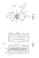
- the heater of FIG. 2 is composed of a burner 21 and a fuel pipe 22, in which as the fuel pipe 22 is connected to the burner 21 by an end thereof while another end of the fuel pipe 22 is connected to a fuel supply, fuel can be fed to the burner 21.
- the flame23 from the burner 21 of the external heater 20 is adapted for heating a forging mold for forging machines or an injection mold for injection molding as the molds are composed of a top die 24 and a bottom die 25 and thus the temperatures of the heated molds can be increased from room temperature to a working temperature.
- the instant mold preheating module in the aforesaid TW patent is a high-frequency induction heating device packed inside ceramics or plastic steel, which can be fitted inside grooves formed on the inserts for using the eddy currents from the heating device to heat up the inserts to a specific temperature in an instant manner.
- the instant heating method and device of molding equipment disclosed in TW Pat. Appl. No. 92123775 is an improvement over that disclosed in TW Pat. Appl. No. 92123778 .
- the high-frequency induction heating energy is designed to work directly on the inserts of a mold for heating the surfaces of the same to a specific temperature in an instant manner, by that not only the preheating efficiency is improved with less energy consumption, but also it can ensure the melted plastic to flow smoothly in the mold cavity for molding.
- the device disclosed in TW Pat. Appl. No. 94127663 is further an improvement over the one disclosed in TW Pat. Appl. No. 92123775 .
- connection between the heating coil and the transformer is redesigned and structured for enabling the two to be detachable, so that the preheating device can be move easily and rapidly around a mold so as to be used for preheating any portion of the mold in a precise manner.
- the object of the present invention is to provide a coaxial cooling/heating coil structure and a mold configured with the same, capable of enhancing the preheating efficiency of the mold while reducing the time required for cooling the mold as the coaxial cooling/heating coil structure is configured with a heat-conducting coil being coaxially disposed inside its cooling channel.
- the present invention provides a coaxial cooling/heating coil structure and a mold configured with the same, in which the coaxial cooling/heating coil is comprised of: a frame, configured with a cooling channel having an inlet, provided for a cooling water to flow therein, and an outlet, provided for discharging the cooling water therefrom; and a heat-conducting coil, disposed inside the cooling channel.
- FIG. 1 is a schematic diagram showing a conventional high-frequency mold structure.
- FIG. 2 is a schematic diagram showing a conventional preheating structure.
- FIG. 3 is a front view of a coaxial cooling/heating coil structure according to a first embodiment of the invention.
- FIG. 4 is an A-A cross sectional view of FIG. 3 .
- FIG. 4A is an enlarged view showing a portion of FIG. 4 .
- FIG. 5 is a front view of a coaxial cooling/heating coil structure according to a second embodiment of the invention.
- FIG. 6 is a front view of a coaxial cooling/heating coil structure according to a third embodiment of the invention.
- FIG. 7 is a cross section diagram showing a supporting structure for supporting a heat-conducting coil in a coaxial cooling/heating coil structure of the invention.
- FIG. 8 is a C-C cross sectional view of FIG. 7 .
- FIG. 9 is a cross section diagram showing another supporting structure for supporting a heat-conducting coil in a coaxial cooling/heating coil structure of the invention.
- FIG. 10 is a schematic diagram showing a high-frequency mold using a coaxial cooling/heating coil structure according to an embodiment of the invention.
- FIG. 11 is an enlarged view showing the D portion of FIG. 10 .
- FIG. 12 is a schematic diagram showing another high-frequency mold using a coaxial cooling/heating coil structure according to an embodiment of the invention.
- FIG. 13 is a schematic diagram showing yet another high-frequency mold using a coaxial cooling/heating coil structure according to an embodiment of the invention.
- the coaxial cooling/heating coil structure 30 in this embodiment comprises: a frame 31; a cooling channel 32, arranged at the frame 31 and configured with an inlet 321, provided for a cooling water to flow therein, and an outlet 322, provided for discharging the cooling water therefrom; and a heat-conducting coil 33, disposed inside the cooling channel 32 and capable of being activated for heating by an high-frequency induction manner.
- the heat-conducting coil 331 is a hollow tube with an internal cooling channel 331 formed therein.
- the internal cooling channel 331 is configured the same as that of the cooling channel 32 as it is also formed with an inlet and outlet and is filled with circulating cooling water. Thereby, the heat-conducting coil 33 is substantially being enclosed and surrounded by cooling water as there are cooling channels formed inside and outside of the heat-conducting coil 33. It is noted that the internal cooling channel 331 is functioned for preventing the heat-conducting coil 33 from overheating so that the cooling water in the internal cooling channel 331 is kept flowing and circulating.
- the cooling channel 32 is designed for cooling down the frame 31 and the heat-conducting coil 33 rapidly, the cooling channel 32 is drained or is being filled with static cooling water when the heat-conducting coil 33 is being activated for heating; and the cooling channel 32 is only being filled with circulating cooling water when the heat-conducting coil 33 is stopped from heating.
- the heat-conducting coil 33 is being wrapped inside an insulating layer 332. It is noted that there is no restriction regarding to the material and the thickness of the insulating layer 332, they can be determined according to actual requirements.
- the coaxial cooling/heating coil structure 30B in this embodiment comprises: a frame 31B; a cooling channel 32B, arranged at the frame 31B and configured with an inlet 321B, provided for a cooling water to flow therein, and an outlet 322B, provided for discharging the cooling water therefrom; and a heat-conducting coil 33B, disposed inside the cooling channel 32B and capable of being activated for heating by an high-frequency induction manner.
- the cooling channel 32 is formed in a shape like a spiral, but the cooling channel 32B of the present embodiment is disposed in a manner that it is zigzagging on a two-dimensional plane. It is noted from the B-B cross section of FIG. 5 , that the coaxial cooling/heating coil structure of the second embodiment is structured similar to that of the first embodiment.
- the cooling channel 32C with the heat-conducting coil 33C that is formed inside the frame 31C is disposed following the irregularity of the frame 31C and is being disposed in a three-dimensional space in a manner that different portions of the cooling channel 32C are extending in the space at different heights.
- the cooling channel can be formed according to actual requirements that it can be formed in a spiral wrapping around a concave cone, a spiral wrapping around a convex cone, or other regular/irregular shapes, and so on.
- FIG. 7 is a cross section diagram showing a supporting structure for supporting a heat-conducting coil in a coaxial cooling/heating coil structure of the invention. Since the heat-conducting coil 33 is disposed inside the cooling channel 32, ideally the heat-conducting coil 33 should be disposed in a way that there should be no physical contact between the heat-conducting coil 33 and the inner wall of the cooling channel 32. Thus, it is required to have a supporting structure which is disposed inside the cooling channel 32 and used for supporting the heat-conducting coil 33 in a manner that the heat-conducting coil 33 is hung inside the cooling channel 32. As shown in FIG. 7 , the supporting structure is composed of at least one supporting arm. Taking the one supporting arm 34 shown in FIG.
- the supporting arm 34 is configured with a hook 341 to be used for clasping the heat-conducting coil 33 so that the heat-conducting coil is supported by the supporting arm 34 and thus hung inside the cooling channel 32 without causing any contact between the two.
- FIG. 7 As the a C-C cross sectional view of FIG. 7 that is shown in FIG. 8 , there can be more than one such supporting arms 34 being disposed inside the cooling channel 32 in an alternating manner while extending toward the center of the cooling channel 32 in arbitrary direction, as the two supporting arms 34, 34a shown in FIG. 8 , while each supporting arm 34 will clasp the heat-conducting coil 33 by its hook, as the two hooks 341, 341a, so as to hang the heat-conducting coil 33 inside the cooling channel 32 without causing any contact between the two.
- FIG. 9 is a cross section diagram showing another supporting structure for supporting a heat-conducting coil in a coaxial cooling/heating coil structure of the invention.
- the supporting structure is composed of a plurality of brackets 35 that are disposed for firmly clamping the heat-conducting coil 33 in the spaces enclosed between the tops thereof so that the heat-conducting coil 33 can be hung inside the cooling channel 32 without causing any contact between the two.
- the amount of the bracket 35 is not limited to a specific number. Basically, one bracket 35 might be sufficient to support and hang the heat-conducting coil 33.
- each pair of brackets 35 it is preferred to dispose the plural brackets 35 in pairs while enabling each pair of brackets 35 to be disposed in the cooling channel 32 at positions symmetrical to each other, as the two shown in FIG. 9 , so that the heat-conducting coil 33 is firmed sandwiched between the gap formed between the top of the paired brackets 35.
- FIG. 10 is a schematic diagram showing a high-frequency mold using a coaxial cooling/heating coil structure according to an embodiment of the invention.
- the high-frequency mold 40 of FIG. 10 is composed of a male die 41 and a female die 42, in which the male die 41 is configured with an insert 43 and the female die 42 is also configured with an insert 44.
- the inserts 43, 44 are formed respectively with mold cavities 431, 441, and there is a coaxial cooling/heating coil structure 50 being configured at a side of the mold corresponding to the male die 41 and a sprue gate 45 being formed on the female die 42.
- the coaxial cooling/heating coil structure 50 comprises: a frame 51; a cooling channel 52, arranged at the frame 51; and a heat-conducting coil 53, coaxially disposed inside the cooling channel 52. Moreover, the coaxial cooling/heating coil structure 50 is arranged abutting against the insert 43 of the male die 41 so that the cooling channel 52 is formed by the enclosure of the frame 51 and the insert 43. In addition, there is a heat-insulating layer 54 disposed between the male die 41, the coaxial cooling/heating coil structure 50 and the insert 43. As the enlarged diagram shown in FIG.
- the heat-insulating layer 54 is disposed for preventing the heat of the heat-conducting coil 53 from being conducted directed to the bulky male die 41 and thus preventing any unnecessary heat loss from happening.
- the material and the thickness of the heat-insulating layer 54 are determined dependent upon actual requirements regarding the size of the mold and the product of the mold, etc., which can be any material and of any thickness only if it can have good high-temperature resistance and heat insulation performance.
- the frame 51 is designed to be integrally formed with the insert 43 so that the heat from the heat-conducting coil 53 can be transferred directly to the insert 43 while the cooling channel 53 is able to work directly to the insert 43 for cooling the same.
- FIG. 12 is a schematic diagram showing another high-frequency mold using a coaxial cooling/heating coil structure according to an embodiment of the invention.
- the high-frequency mold 60 of FIG. 12 is composed of a male die 61 and a female die 62, in which the male die 61 is configured with an insert 63 and the female die 62 is also configured with an insert 64.
- the inserts 63, 64 are formed respectively with mold cavities 631, 641, and there is a coaxial cooling/heating coil structure 70 being configured at a position between the male die 41 and the female die 62.
- the coaxial cooling/heating coil structure 70 comprises: a frame 57; a cooling channel, arranged at the frame 71; and a heat-conducting coil, coaxially disposed inside the cooling channel.
- the frame 71 is mounted on a mobile arm 74 for enabling the same to be moved along with the movement of the mobile arm 74. That is, the mobile arm 74 is able to place the frame 71 into a space between the male die 61 and the female die 62, or pull the frame 71 out of the space between the male die 61 and the female die 62, depending on whether it is intended to preheat the mold cavities 631, 641 or is intended for the mold cavities 631, 641 to cool down.
- FIG. 13 is a schematic diagram showing yet another high-frequency mold using a coaxial cooling/heating coil structure according to an embodiment of the invention.
- the high-frequency mold 80 of FIG. 13 is composed of three dies, which are a male die 81, a female die 82 and a sub-die 88.
- there are two coaxial cooling/heating coil structures 70, 70a being arranged respectively at positions between the male die 81 and the sub-die 88, and between the female die 82 and the sub-die 88, whereas the two coaxial cooling/heating coil structures 70, 70a are mounted respectively on their corresponding mobile arms 74, 74a.
- the mobile arms 74, 74a are able to place their corresponding coaxial cooling/heating coil structures 70, 70a into their corresponding spaces between sub-die 88 and the male die 81, and between the sub-die 88 and the female die 82. It is noted that by the aforesaid structure, molds of various configurations can be preheated by the high frequency electromagnetic induction waves emitted from the two coaxial cooling/heating coil structures 70, 70a.
- the coaxial cooling/heating coil structure and the mold configured with the same provided in the present invention not only can enhance the preheating efficiency of the mold as the coaxial cooling/heating coil structure is able to preheat the mold rapidly and uniformly with less energy consumption, but also it can reduce the time required for cooling the mold as well.
Landscapes
- Physics & Mathematics (AREA)
- Health & Medical Sciences (AREA)
- Engineering & Computer Science (AREA)
- Mechanical Engineering (AREA)
- Electromagnetism (AREA)
- Toxicology (AREA)
- Manufacturing & Machinery (AREA)
- Oral & Maxillofacial Surgery (AREA)
- Thermal Sciences (AREA)
- Moulds For Moulding Plastics Or The Like (AREA)
- General Induction Heating (AREA)
Applications Claiming Priority (1)
| Application Number | Priority Date | Filing Date | Title |
|---|---|---|---|
| TW097149664A TWI389600B (zh) | 2008-12-19 | 2008-12-19 | Coaxial cooling and thermally conductive coil construction and molds with coaxial cooling and thermally conductive coil construction |
Publications (2)
| Publication Number | Publication Date |
|---|---|
| EP2199057A1 true EP2199057A1 (fr) | 2010-06-23 |
| EP2199057B1 EP2199057B1 (fr) | 2013-04-03 |
Family
ID=41796141
Family Applications (1)
| Application Number | Title | Priority Date | Filing Date |
|---|---|---|---|
| EP09180023A Not-in-force EP2199057B1 (fr) | 2008-12-19 | 2009-12-18 | Structure de bobine de refroidissement/chauffage coaxial et le moule configuré avec celui-ci |
Country Status (4)
| Country | Link |
|---|---|
| US (1) | US8052415B2 (fr) |
| EP (1) | EP2199057B1 (fr) |
| JP (1) | JP4982519B2 (fr) |
| TW (1) | TWI389600B (fr) |
Cited By (7)
| Publication number | Priority date | Publication date | Assignee | Title |
|---|---|---|---|---|
| CN102672058A (zh) * | 2012-05-08 | 2012-09-19 | 哈尔滨工业大学 | 一种管材热成形设备 |
| WO2013190020A1 (fr) * | 2012-06-19 | 2013-12-27 | Roctool | Moule à chauffage et refroidissement rapides |
| CN108601128A (zh) * | 2018-04-19 | 2018-09-28 | 丰泽智能装备股份有限公司 | 电磁加热模具 |
| CN109909383A (zh) * | 2019-03-12 | 2019-06-21 | 华电电力科学研究院有限公司 | 松弛法直轴水冷式加热装置 |
| IT201800002739A1 (it) * | 2018-02-16 | 2019-08-16 | Atos Spa | Induttore per il preriscaldamento di stampi |
| CN112355271A (zh) * | 2020-10-30 | 2021-02-12 | 郭凯 | 一种用于波纹钢板模具压铸过程中预热的加热装置 |
| DE102021123237A1 (de) | 2021-09-08 | 2023-03-09 | Dr. Ing. H.C. F. Porsche Aktiengesellschaft | Werkzeugzentralkern zum Kunststoff-Gießen einer Statorumspritzung für eine elektrische Traktionsmaschine |
Families Citing this family (22)
| Publication number | Priority date | Publication date | Assignee | Title |
|---|---|---|---|---|
| WO2010050099A1 (fr) * | 2008-10-28 | 2010-05-06 | 三菱重工プラスチックテクノロジー株式会社 | Machine de moulage par injection et procédé de moulage par injection |
| TW201036527A (en) * | 2009-03-19 | 2010-10-01 | Acbel Polytech Inc | Large-area liquid-cooled heat-dissipation device |
| JP5243362B2 (ja) * | 2009-07-17 | 2013-07-24 | 株式会社ホンダロック | 金型の加熱・冷却構造 |
| US8966208B2 (en) * | 2010-02-25 | 2015-02-24 | Conversant Ip Management Inc. | Semiconductor memory device with plural memory die and controller die |
| US20190118442A9 (en) * | 2010-04-20 | 2019-04-25 | Honda Motor Co., Ltd. | Conforming cooling method and mold |
| CN102407594B (zh) * | 2010-09-17 | 2014-11-05 | 本田技研工业株式会社 | 成形装置及成形方法 |
| KR101876373B1 (ko) * | 2011-05-20 | 2018-07-11 | 삼성전자주식회사 | 사출 금형장치 |
| EP2527125B1 (fr) * | 2011-05-25 | 2018-05-09 | LG Electronics Inc. | Appareil de moulage |
| TWI421161B (zh) * | 2011-07-13 | 2014-01-01 | Quanta Comp Inc | 高週波電磁感應加熱裝置及使用其加熱模具表面的方法 |
| CN103826824B (zh) * | 2011-07-27 | 2016-12-21 | 弗莱克斯电子有限责任公司 | 复合组件的温度控制成型 |
| DE102011053867B4 (de) * | 2011-09-22 | 2015-08-06 | Dr. Schneider Kunststoffwerke Gmbh | Spritzgießwerkzeug mit Induktor für die Herstellung von Kunststoffformteilen |
| EP2761974B1 (fr) * | 2011-09-29 | 2022-06-01 | Watlow Electric Manufacturing Company | Système de régulation de température à dynamique élevée |
| DE102012103120B4 (de) * | 2012-04-11 | 2025-04-30 | Günther Heisskanaltechnik Gmbh | Werkzeugeinsatz mit Schichtheizung, Formplatte mit einem solchen Werkzeugeinsatz und Verfahren zum Betrieb eines solchen Werkzeugeinsatzes |
| US8770968B2 (en) * | 2012-04-13 | 2014-07-08 | GM Global Technology Operations LLC | Injection molding tool with embedded induction heater |
| US9938178B2 (en) * | 2013-08-15 | 2018-04-10 | Corning Incorporated | Methods of manufacturing glass articles using anisothermal temperature profiles |
| WO2016089373A1 (fr) * | 2014-12-02 | 2016-06-09 | Halliburton Energy Services, Inc. | Systèmes de moule à échange thermique intégré |
| EP3546199A1 (fr) * | 2018-03-28 | 2019-10-02 | Top Cap Holding GmbH | Procédé de fabrication d'un couvercle de canette en matériau composite |
| DE102018107795A1 (de) * | 2018-04-03 | 2019-10-10 | Volkswagen Aktiengesellschaft | Verfahren zur Herstellung eines 3D-gedruckten Werkzeugs sowie ein solches 3D-gedrucktes Werkzeug und Verwendung eines solchen 3D-gedruckten Werkzeugs |
| CN109605696A (zh) * | 2018-12-14 | 2019-04-12 | 天津恒创立达科技发展有限公司 | 一种电加热模具 |
| CN111716728B (zh) * | 2020-05-26 | 2021-12-17 | 上海峰晟机械设备有限公司 | 带有氮气灭火冷却机构的滤芯端盖焊接模具 |
| TWI817030B (zh) | 2020-08-04 | 2023-10-01 | 中原大學 | 射出成型設備及射出成型方法 |
| CN115255245B (zh) * | 2022-07-21 | 2024-02-02 | 江苏辰顺精密科技有限公司 | 一种用于提高热锻效率的铝件热锻模具 |
Citations (2)
| Publication number | Priority date | Publication date | Assignee | Title |
|---|---|---|---|---|
| JP2002079559A (ja) | 2000-07-07 | 2002-03-19 | Michiya Kakinuma | 金型温度制御装置 |
| EP1800829A1 (fr) | 2005-12-22 | 2007-06-27 | Thermal Cyclic Technologies TCTech i Stockholm AB | Moule à injecter avec chauffage par induction et procédé de moulage avec une étappe de chauffage par induction. |
Family Cites Families (16)
| Publication number | Priority date | Publication date | Assignee | Title |
|---|---|---|---|---|
| JPS63309408A (ja) * | 1987-06-12 | 1988-12-16 | Inoue Japax Res Inc | 加熱成形用型装置 |
| DE3811112A1 (de) * | 1988-03-31 | 1989-10-12 | Fritz Mueller | Spritzgussverfahren fuer kunststoffe und spritzgussform |
| JP2826553B2 (ja) * | 1989-06-09 | 1998-11-18 | 旭化成工業株式会社 | 加飾成形方法及びその装置 |
| JPH0759368B2 (ja) * | 1989-07-28 | 1995-06-28 | 日本ジーイープラスチックス株式会社 | 金 型 |
| ATE98153T1 (de) * | 1990-03-03 | 1993-12-15 | Guenther Herbert Gmbh | Verteiler. |
| JP3438908B2 (ja) * | 1993-05-21 | 2003-08-18 | オリンパス光学工業株式会社 | 射出成形用ヒートサイクルシステム |
| US5423670A (en) * | 1993-10-08 | 1995-06-13 | Hamel; Julio E. | Enhanced thermal transfer injection molding apparatus |
| JPH08230005A (ja) * | 1995-02-28 | 1996-09-10 | Kyowa Kogyo Kk | 射出成形方法及びその金型 |
| JP2000167526A (ja) * | 1998-12-08 | 2000-06-20 | Kurabe Ind Co Ltd | 厨芥処理機用脱臭器 |
| DE10029437B4 (de) * | 2000-06-21 | 2005-11-17 | Heraeus Noblelight Gmbh | Infrarotstrahler und Verfahren zum Betreiben eines solchen Infrarotstrahlers |
| JP2002299031A (ja) * | 2001-03-28 | 2002-10-11 | Kobe Steel Ltd | 高周波誘導加熱コイル、高周波誘導加熱装置及び溶接管の製造方法 |
| US7034263B2 (en) * | 2003-07-02 | 2006-04-25 | Itherm Technologies, Lp | Apparatus and method for inductive heating |
| TWI224548B (en) | 2003-08-28 | 2004-12-01 | Shia-Chung Chen | The instant heating method and device of molding equipment |
| TWI228945B (en) | 2003-08-28 | 2005-03-01 | Shia-Chung Chen | The method and device to increase distribution uniformity of magnetic force |
| TW200706333A (en) | 2005-08-12 | 2007-02-16 | Shia-Chung Chen | Retractable device for high frequency preheating mold |
| KR100644926B1 (ko) * | 2005-08-30 | 2006-11-10 | 강명호 | 분리형 금형을 구비한 사출장치 및 그 제어방법 |
-
2008
- 2008-12-19 TW TW097149664A patent/TWI389600B/zh not_active IP Right Cessation
-
2009
- 2009-03-27 JP JP2009078593A patent/JP4982519B2/ja not_active Expired - Fee Related
- 2009-12-18 US US12/641,973 patent/US8052415B2/en not_active Expired - Fee Related
- 2009-12-18 EP EP09180023A patent/EP2199057B1/fr not_active Not-in-force
Patent Citations (2)
| Publication number | Priority date | Publication date | Assignee | Title |
|---|---|---|---|---|
| JP2002079559A (ja) | 2000-07-07 | 2002-03-19 | Michiya Kakinuma | 金型温度制御装置 |
| EP1800829A1 (fr) | 2005-12-22 | 2007-06-27 | Thermal Cyclic Technologies TCTech i Stockholm AB | Moule à injecter avec chauffage par induction et procédé de moulage avec une étappe de chauffage par induction. |
Cited By (13)
| Publication number | Priority date | Publication date | Assignee | Title |
|---|---|---|---|---|
| CN102672058A (zh) * | 2012-05-08 | 2012-09-19 | 哈尔滨工业大学 | 一种管材热成形设备 |
| WO2013190020A1 (fr) * | 2012-06-19 | 2013-12-27 | Roctool | Moule à chauffage et refroidissement rapides |
| KR20150022891A (ko) * | 2012-06-19 | 2015-03-04 | 록툴 | 신속 가열 및 냉각 주형 |
| US9248598B2 (en) | 2012-06-19 | 2016-02-02 | Roctool | Quick heating and cooling mold |
| RU2630256C2 (ru) * | 2012-06-19 | 2017-09-06 | Роктул | Пресс-форма с быстрым нагревом и охлаждением |
| US10052803B2 (en) | 2012-06-19 | 2018-08-21 | Roctool | Quick heating and cooling mold |
| EP3528596A1 (fr) * | 2018-02-16 | 2019-08-21 | Atos S.P.A. | Inducteur de préchauffage de moules |
| IT201800002739A1 (it) * | 2018-02-16 | 2019-08-16 | Atos Spa | Induttore per il preriscaldamento di stampi |
| CN108601128A (zh) * | 2018-04-19 | 2018-09-28 | 丰泽智能装备股份有限公司 | 电磁加热模具 |
| CN108601128B (zh) * | 2018-04-19 | 2024-05-24 | 丰泽智能装备股份有限公司 | 电磁加热模具 |
| CN109909383A (zh) * | 2019-03-12 | 2019-06-21 | 华电电力科学研究院有限公司 | 松弛法直轴水冷式加热装置 |
| CN112355271A (zh) * | 2020-10-30 | 2021-02-12 | 郭凯 | 一种用于波纹钢板模具压铸过程中预热的加热装置 |
| DE102021123237A1 (de) | 2021-09-08 | 2023-03-09 | Dr. Ing. H.C. F. Porsche Aktiengesellschaft | Werkzeugzentralkern zum Kunststoff-Gießen einer Statorumspritzung für eine elektrische Traktionsmaschine |
Also Published As
| Publication number | Publication date |
|---|---|
| JP4982519B2 (ja) | 2012-07-25 |
| TWI389600B (zh) | 2013-03-11 |
| JP2010143217A (ja) | 2010-07-01 |
| US20100159061A1 (en) | 2010-06-24 |
| TW201026158A (en) | 2010-07-01 |
| EP2199057B1 (fr) | 2013-04-03 |
| US8052415B2 (en) | 2011-11-08 |
Similar Documents
| Publication | Publication Date | Title |
|---|---|---|
| EP2199057B1 (fr) | Structure de bobine de refroidissement/chauffage coaxial et le moule configuré avec celui-ci | |
| JP2009000863A (ja) | 成形金型及びその制御方法 | |
| CN1582222A (zh) | 用于模制产品的方法以及其中所使用的模具 | |
| CN109081563B (zh) | 3d玻璃热弯机和3d玻璃成型方法 | |
| CN103660256A (zh) | 通过使与模具外表面接触的传热流体流通冷却模具的方法 | |
| JP2010000784A5 (fr) | ||
| US6960746B2 (en) | Device for instantly pre-heating dies | |
| CN218171223U (zh) | 一种具有快速冷却结构的模具 | |
| CN206717000U (zh) | 压铸模具及压铸装置 | |
| KR20160149638A (ko) | 인고트 제조장치 | |
| CN115071085B (zh) | 一种塑料模具的冷却装置 | |
| WPAT | CHEN et al.(43) Pub. Date: Jun. 24, 2010 | |
| KR101623030B1 (ko) | 급속 열확산 사출금형 | |
| KR101711290B1 (ko) | 튜브연결구 성형장치 및 이 성형장치로 성형된 튜브연결구 | |
| CN208584783U (zh) | 一种波纹管冷却输出装置 | |
| CN210389971U (zh) | 一种汽车配件用注塑模具 | |
| CN209098501U (zh) | 加热管和具有该加热管的加热模组 | |
| CN106313436A (zh) | 高光塑料件的注塑模具及加工方法 | |
| CN223431952U (zh) | 一种模具冷却装置 | |
| CN220862696U (zh) | 一种具有高效冷却循环回路的薄壁工件成型模具 | |
| CN211993773U (zh) | 制造热塑管道用芯模 | |
| KR20150003740U (ko) | 사출금형의 코어 냉각을 위한 배플관 및 이를 이용한 사출금형의 코어 냉각장치 | |
| CN212219106U (zh) | 一种pvc化妆品包装盒的模具 | |
| CN214214616U (zh) | 一种注塑模具 | |
| KR100828182B1 (ko) | 3차원 열교환 구조를 구비한 금형 및 그 제작방법 |
Legal Events
| Date | Code | Title | Description |
|---|---|---|---|
| PUAI | Public reference made under article 153(3) epc to a published international application that has entered the european phase |
Free format text: ORIGINAL CODE: 0009012 |
|
| AK | Designated contracting states |
Kind code of ref document: A1 Designated state(s): AT BE BG CH CY CZ DE DK EE ES FI FR GB GR HR HU IE IS IT LI LT LU LV MC MK MT NL NO PL PT RO SE SI SK SM TR |
|
| AX | Request for extension of the european patent |
Extension state: AL BA RS |
|
| 17P | Request for examination filed |
Effective date: 20101223 |
|
| 17Q | First examination report despatched |
Effective date: 20110216 |
|
| GRAP | Despatch of communication of intention to grant a patent |
Free format text: ORIGINAL CODE: EPIDOSNIGR1 |
|
| GRAS | Grant fee paid |
Free format text: ORIGINAL CODE: EPIDOSNIGR3 |
|
| GRAA | (expected) grant |
Free format text: ORIGINAL CODE: 0009210 |
|
| AK | Designated contracting states |
Kind code of ref document: B1 Designated state(s): AT BE BG CH CY CZ DE DK EE ES FI FR GB GR HR HU IE IS IT LI LT LU LV MC MK MT NL NO PL PT RO SE SI SK SM TR |
|
| REG | Reference to a national code |
Ref country code: GB Ref legal event code: FG4D |
|
| REG | Reference to a national code |
Ref country code: AT Ref legal event code: REF Ref document number: 604416 Country of ref document: AT Kind code of ref document: T Effective date: 20130415 Ref country code: CH Ref legal event code: EP |
|
| REG | Reference to a national code |
Ref country code: IE Ref legal event code: FG4D |
|
| REG | Reference to a national code |
Ref country code: DE Ref legal event code: R096 Ref document number: 602009014604 Country of ref document: DE Effective date: 20130529 |
|
| REG | Reference to a national code |
Ref country code: AT Ref legal event code: MK05 Ref document number: 604416 Country of ref document: AT Kind code of ref document: T Effective date: 20130403 |
|
| PG25 | Lapsed in a contracting state [announced via postgrant information from national office to epo] |
Ref country code: SI Free format text: LAPSE BECAUSE OF FAILURE TO SUBMIT A TRANSLATION OF THE DESCRIPTION OR TO PAY THE FEE WITHIN THE PRESCRIBED TIME-LIMIT Effective date: 20130403 |
|
| REG | Reference to a national code |
Ref country code: NL Ref legal event code: VDEP Effective date: 20130403 |
|
| REG | Reference to a national code |
Ref country code: LT Ref legal event code: MG4D |
|
| PG25 | Lapsed in a contracting state [announced via postgrant information from national office to epo] |
Ref country code: PT Free format text: LAPSE BECAUSE OF FAILURE TO SUBMIT A TRANSLATION OF THE DESCRIPTION OR TO PAY THE FEE WITHIN THE PRESCRIBED TIME-LIMIT Effective date: 20130805 Ref country code: LT Free format text: LAPSE BECAUSE OF FAILURE TO SUBMIT A TRANSLATION OF THE DESCRIPTION OR TO PAY THE FEE WITHIN THE PRESCRIBED TIME-LIMIT Effective date: 20130403 Ref country code: GR Free format text: LAPSE BECAUSE OF FAILURE TO SUBMIT A TRANSLATION OF THE DESCRIPTION OR TO PAY THE FEE WITHIN THE PRESCRIBED TIME-LIMIT Effective date: 20130704 Ref country code: SE Free format text: LAPSE BECAUSE OF FAILURE TO SUBMIT A TRANSLATION OF THE DESCRIPTION OR TO PAY THE FEE WITHIN THE PRESCRIBED TIME-LIMIT Effective date: 20130403 Ref country code: AT Free format text: LAPSE BECAUSE OF FAILURE TO SUBMIT A TRANSLATION OF THE DESCRIPTION OR TO PAY THE FEE WITHIN THE PRESCRIBED TIME-LIMIT Effective date: 20130403 Ref country code: BE Free format text: LAPSE BECAUSE OF FAILURE TO SUBMIT A TRANSLATION OF THE DESCRIPTION OR TO PAY THE FEE WITHIN THE PRESCRIBED TIME-LIMIT Effective date: 20130403 Ref country code: ES Free format text: LAPSE BECAUSE OF FAILURE TO SUBMIT A TRANSLATION OF THE DESCRIPTION OR TO PAY THE FEE WITHIN THE PRESCRIBED TIME-LIMIT Effective date: 20130714 Ref country code: NL Free format text: LAPSE BECAUSE OF FAILURE TO SUBMIT A TRANSLATION OF THE DESCRIPTION OR TO PAY THE FEE WITHIN THE PRESCRIBED TIME-LIMIT Effective date: 20130403 Ref country code: IS Free format text: LAPSE BECAUSE OF FAILURE TO SUBMIT A TRANSLATION OF THE DESCRIPTION OR TO PAY THE FEE WITHIN THE PRESCRIBED TIME-LIMIT Effective date: 20130803 Ref country code: FI Free format text: LAPSE BECAUSE OF FAILURE TO SUBMIT A TRANSLATION OF THE DESCRIPTION OR TO PAY THE FEE WITHIN THE PRESCRIBED TIME-LIMIT Effective date: 20130403 Ref country code: NO Free format text: LAPSE BECAUSE OF FAILURE TO SUBMIT A TRANSLATION OF THE DESCRIPTION OR TO PAY THE FEE WITHIN THE PRESCRIBED TIME-LIMIT Effective date: 20130703 |
|
| PG25 | Lapsed in a contracting state [announced via postgrant information from national office to epo] |
Ref country code: HR Free format text: LAPSE BECAUSE OF FAILURE TO SUBMIT A TRANSLATION OF THE DESCRIPTION OR TO PAY THE FEE WITHIN THE PRESCRIBED TIME-LIMIT Effective date: 20130403 Ref country code: PL Free format text: LAPSE BECAUSE OF FAILURE TO SUBMIT A TRANSLATION OF THE DESCRIPTION OR TO PAY THE FEE WITHIN THE PRESCRIBED TIME-LIMIT Effective date: 20130403 Ref country code: LV Free format text: LAPSE BECAUSE OF FAILURE TO SUBMIT A TRANSLATION OF THE DESCRIPTION OR TO PAY THE FEE WITHIN THE PRESCRIBED TIME-LIMIT Effective date: 20130403 Ref country code: BG Free format text: LAPSE BECAUSE OF FAILURE TO SUBMIT A TRANSLATION OF THE DESCRIPTION OR TO PAY THE FEE WITHIN THE PRESCRIBED TIME-LIMIT Effective date: 20130703 Ref country code: CY Free format text: LAPSE BECAUSE OF FAILURE TO SUBMIT A TRANSLATION OF THE DESCRIPTION OR TO PAY THE FEE WITHIN THE PRESCRIBED TIME-LIMIT Effective date: 20130403 |
|
| PG25 | Lapsed in a contracting state [announced via postgrant information from national office to epo] |
Ref country code: CZ Free format text: LAPSE BECAUSE OF FAILURE TO SUBMIT A TRANSLATION OF THE DESCRIPTION OR TO PAY THE FEE WITHIN THE PRESCRIBED TIME-LIMIT Effective date: 20130403 Ref country code: EE Free format text: LAPSE BECAUSE OF FAILURE TO SUBMIT A TRANSLATION OF THE DESCRIPTION OR TO PAY THE FEE WITHIN THE PRESCRIBED TIME-LIMIT Effective date: 20130403 Ref country code: SK Free format text: LAPSE BECAUSE OF FAILURE TO SUBMIT A TRANSLATION OF THE DESCRIPTION OR TO PAY THE FEE WITHIN THE PRESCRIBED TIME-LIMIT Effective date: 20130403 Ref country code: DK Free format text: LAPSE BECAUSE OF FAILURE TO SUBMIT A TRANSLATION OF THE DESCRIPTION OR TO PAY THE FEE WITHIN THE PRESCRIBED TIME-LIMIT Effective date: 20130403 |
|
| PLBE | No opposition filed within time limit |
Free format text: ORIGINAL CODE: 0009261 |
|
| STAA | Information on the status of an ep patent application or granted ep patent |
Free format text: STATUS: NO OPPOSITION FILED WITHIN TIME LIMIT |
|
| PG25 | Lapsed in a contracting state [announced via postgrant information from national office to epo] |
Ref country code: RO Free format text: LAPSE BECAUSE OF FAILURE TO SUBMIT A TRANSLATION OF THE DESCRIPTION OR TO PAY THE FEE WITHIN THE PRESCRIBED TIME-LIMIT Effective date: 20130403 Ref country code: IT Free format text: LAPSE BECAUSE OF FAILURE TO SUBMIT A TRANSLATION OF THE DESCRIPTION OR TO PAY THE FEE WITHIN THE PRESCRIBED TIME-LIMIT Effective date: 20130403 |
|
| 26N | No opposition filed |
Effective date: 20140106 |
|
| REG | Reference to a national code |
Ref country code: DE Ref legal event code: R097 Ref document number: 602009014604 Country of ref document: DE Effective date: 20140106 |
|
| REG | Reference to a national code |
Ref country code: CH Ref legal event code: PL |
|
| PG25 | Lapsed in a contracting state [announced via postgrant information from national office to epo] |
Ref country code: LU Free format text: LAPSE BECAUSE OF FAILURE TO SUBMIT A TRANSLATION OF THE DESCRIPTION OR TO PAY THE FEE WITHIN THE PRESCRIBED TIME-LIMIT Effective date: 20131218 Ref country code: MC Free format text: LAPSE BECAUSE OF FAILURE TO SUBMIT A TRANSLATION OF THE DESCRIPTION OR TO PAY THE FEE WITHIN THE PRESCRIBED TIME-LIMIT Effective date: 20130403 |
|
| REG | Reference to a national code |
Ref country code: IE Ref legal event code: MM4A |
|
| PG25 | Lapsed in a contracting state [announced via postgrant information from national office to epo] |
Ref country code: LI Free format text: LAPSE BECAUSE OF NON-PAYMENT OF DUE FEES Effective date: 20131231 Ref country code: IE Free format text: LAPSE BECAUSE OF NON-PAYMENT OF DUE FEES Effective date: 20131218 Ref country code: CH Free format text: LAPSE BECAUSE OF NON-PAYMENT OF DUE FEES Effective date: 20131231 |
|
| PG25 | Lapsed in a contracting state [announced via postgrant information from national office to epo] |
Ref country code: SM Free format text: LAPSE BECAUSE OF FAILURE TO SUBMIT A TRANSLATION OF THE DESCRIPTION OR TO PAY THE FEE WITHIN THE PRESCRIBED TIME-LIMIT Effective date: 20130403 |
|
| PG25 | Lapsed in a contracting state [announced via postgrant information from national office to epo] |
Ref country code: TR Free format text: LAPSE BECAUSE OF FAILURE TO SUBMIT A TRANSLATION OF THE DESCRIPTION OR TO PAY THE FEE WITHIN THE PRESCRIBED TIME-LIMIT Effective date: 20130403 |
|
| PG25 | Lapsed in a contracting state [announced via postgrant information from national office to epo] |
Ref country code: HU Free format text: LAPSE BECAUSE OF FAILURE TO SUBMIT A TRANSLATION OF THE DESCRIPTION OR TO PAY THE FEE WITHIN THE PRESCRIBED TIME-LIMIT; INVALID AB INITIO Effective date: 20091218 Ref country code: MK Free format text: LAPSE BECAUSE OF FAILURE TO SUBMIT A TRANSLATION OF THE DESCRIPTION OR TO PAY THE FEE WITHIN THE PRESCRIBED TIME-LIMIT Effective date: 20130403 |
|
| PG25 | Lapsed in a contracting state [announced via postgrant information from national office to epo] |
Ref country code: MT Free format text: LAPSE BECAUSE OF FAILURE TO SUBMIT A TRANSLATION OF THE DESCRIPTION OR TO PAY THE FEE WITHIN THE PRESCRIBED TIME-LIMIT Effective date: 20130403 |
|
| REG | Reference to a national code |
Ref country code: FR Ref legal event code: PLFP Year of fee payment: 7 |
|
| REG | Reference to a national code |
Ref country code: FR Ref legal event code: PLFP Year of fee payment: 8 |
|
| REG | Reference to a national code |
Ref country code: FR Ref legal event code: PLFP Year of fee payment: 9 |
|
| REG | Reference to a national code |
Ref country code: FR Ref legal event code: PLFP Year of fee payment: 10 |
|
| PGFP | Annual fee paid to national office [announced via postgrant information from national office to epo] |
Ref country code: FR Payment date: 20210810 Year of fee payment: 13 |
|
| PGFP | Annual fee paid to national office [announced via postgrant information from national office to epo] |
Ref country code: GB Payment date: 20211001 Year of fee payment: 13 Ref country code: DE Payment date: 20210827 Year of fee payment: 13 |
|
| REG | Reference to a national code |
Ref country code: DE Ref legal event code: R119 Ref document number: 602009014604 Country of ref document: DE |
|
| GBPC | Gb: european patent ceased through non-payment of renewal fee |
Effective date: 20221218 |
|
| PG25 | Lapsed in a contracting state [announced via postgrant information from national office to epo] |
Ref country code: GB Free format text: LAPSE BECAUSE OF NON-PAYMENT OF DUE FEES Effective date: 20221218 Ref country code: DE Free format text: LAPSE BECAUSE OF NON-PAYMENT OF DUE FEES Effective date: 20230701 |
|
| PG25 | Lapsed in a contracting state [announced via postgrant information from national office to epo] |
Ref country code: FR Free format text: LAPSE BECAUSE OF NON-PAYMENT OF DUE FEES Effective date: 20221231 |