EP2198217B1 - Wärmesteuersystem - Google Patents
Wärmesteuersystem Download PDFInfo
- Publication number
- EP2198217B1 EP2198217B1 EP08837303.0A EP08837303A EP2198217B1 EP 2198217 B1 EP2198217 B1 EP 2198217B1 EP 08837303 A EP08837303 A EP 08837303A EP 2198217 B1 EP2198217 B1 EP 2198217B1
- Authority
- EP
- European Patent Office
- Prior art keywords
- evaporator
- temperature
- refrigerant
- load
- control system
- Prior art date
- Legal status (The legal status is an assumption and is not a legal conclusion. Google has not performed a legal analysis and makes no representation as to the accuracy of the status listed.)
- Not-in-force
Links
Images


Classifications
-
- F—MECHANICAL ENGINEERING; LIGHTING; HEATING; WEAPONS; BLASTING
- F25—REFRIGERATION OR COOLING; COMBINED HEATING AND REFRIGERATION SYSTEMS; HEAT PUMP SYSTEMS; MANUFACTURE OR STORAGE OF ICE; LIQUEFACTION SOLIDIFICATION OF GASES
- F25B—REFRIGERATION MACHINES, PLANTS OR SYSTEMS; COMBINED HEATING AND REFRIGERATION SYSTEMS; HEAT PUMP SYSTEMS
- F25B40/00—Subcoolers, desuperheaters or superheaters
-
- F—MECHANICAL ENGINEERING; LIGHTING; HEATING; WEAPONS; BLASTING
- F25—REFRIGERATION OR COOLING; COMBINED HEATING AND REFRIGERATION SYSTEMS; HEAT PUMP SYSTEMS; MANUFACTURE OR STORAGE OF ICE; LIQUEFACTION SOLIDIFICATION OF GASES
- F25B—REFRIGERATION MACHINES, PLANTS OR SYSTEMS; COMBINED HEATING AND REFRIGERATION SYSTEMS; HEAT PUMP SYSTEMS
- F25B41/00—Fluid-circulation arrangements
- F25B41/30—Expansion means; Dispositions thereof
- F25B41/39—Dispositions with two or more expansion means arranged in series, i.e. multi-stage expansion, on a refrigerant line leading to the same evaporator
-
- F—MECHANICAL ENGINEERING; LIGHTING; HEATING; WEAPONS; BLASTING
- F25—REFRIGERATION OR COOLING; COMBINED HEATING AND REFRIGERATION SYSTEMS; HEAT PUMP SYSTEMS; MANUFACTURE OR STORAGE OF ICE; LIQUEFACTION SOLIDIFICATION OF GASES
- F25B—REFRIGERATION MACHINES, PLANTS OR SYSTEMS; COMBINED HEATING AND REFRIGERATION SYSTEMS; HEAT PUMP SYSTEMS
- F25B2400/00—General features or devices for refrigeration machines, plants or systems, combined heating and refrigeration systems or heat-pump systems, i.e. not limited to a particular subgroup of F25B
- F25B2400/04—Refrigeration circuit bypassing means
- F25B2400/0403—Refrigeration circuit bypassing means for the condenser
-
- F—MECHANICAL ENGINEERING; LIGHTING; HEATING; WEAPONS; BLASTING
- F25—REFRIGERATION OR COOLING; COMBINED HEATING AND REFRIGERATION SYSTEMS; HEAT PUMP SYSTEMS; MANUFACTURE OR STORAGE OF ICE; LIQUEFACTION SOLIDIFICATION OF GASES
- F25B—REFRIGERATION MACHINES, PLANTS OR SYSTEMS; COMBINED HEATING AND REFRIGERATION SYSTEMS; HEAT PUMP SYSTEMS
- F25B2600/00—Control issues
- F25B2600/02—Compressor control
- F25B2600/026—Compressor control by controlling unloaders
- F25B2600/0261—Compressor control by controlling unloaders external to the compressor
-
- F—MECHANICAL ENGINEERING; LIGHTING; HEATING; WEAPONS; BLASTING
- F25—REFRIGERATION OR COOLING; COMBINED HEATING AND REFRIGERATION SYSTEMS; HEAT PUMP SYSTEMS; MANUFACTURE OR STORAGE OF ICE; LIQUEFACTION SOLIDIFICATION OF GASES
- F25B—REFRIGERATION MACHINES, PLANTS OR SYSTEMS; COMBINED HEATING AND REFRIGERATION SYSTEMS; HEAT PUMP SYSTEMS
- F25B2600/00—Control issues
- F25B2600/25—Control of valves
- F25B2600/2513—Expansion valves
Definitions
- thermodynamic systems and methods which utilize vapor cycle processes, such as systems for air conditioning, refrigeration and other temperature control applications, and more particularly to providing improvements in efficiency in such systems and methods by using novel approaches to thermodynamic sequencing.
- the Goth et al patent does not teach control at a selected or variable temperature level, and is concerned with increasing the temperature level by adding one or more bursts of hot gas for the purpose of avoiding water condensing on sensitive electronic circuits. It accordingly is not useful as a basis for generating precisely controlled temperature levels across a range of temperatures.
- patent US 5,245,833 to V. C. Mei et al entitled “Liquid Over-Feeding Air Conditioning System and Method” discloses a "liquid over-feeding" operation in which heat is exchanged in an accumulator-heat exchanger. This exchange is between a hot liquid refrigerant, and a cooler output refrigerant, after which the refrigerant is expanded for cooling before being applied to the evaporative load. This sequence subcools the refrigerant to allow more of the evaporator surface to be used for cooling.
- JPH05 196321 A discloses a thermal control system using a refrigerant and including a refrigeration loop of operative elements incorporating a compressor, a condenser, and an expansion device in sequence, in thermal communication with an evaporator comprising the load to be cooled, comprising a subsidiary heat exchange loop disposed between the expansion device and the evaporator and including a heat exchanger coupling the expansion device to the evaporator on one side and the output from the evaporator to the compressor on the other side, the loop further including a differential pressure device between the counter-current heat exchanger and the evaporator, in accordance with the preamble of claim 1.
- thermodynamics of basic vapor cycle sequence that provides meaningful efficiency improvement, reductions in energy costs, or both, can have broad consequences for vapor cycle systems.
- Improvements in vapor cycle systems used for refrigeration or heat exchange are realized by modifying the conventional vapor cycle to incorporate an additional thermal exchange step after expansion of compressed condensed refrigerant.
- This interchange of thermal energy is then between the expanded refrigerant and the return flow from the evaporator and is accompanied by a controlled pressure drop, which introduces enhanced post condensing (EPC).
- EPC enhanced post condensing
- the post condensation lowers the quality level (ratio of vapor mass to total mass) of refrigerant delivered to the evaporator and raises the effective heat transfer coefficient (h) during energy exchange with the load.
- This expedient increases the bulk density of the mass moving through the evaporator and lowers the pressure drop introduced, minimizing heat transfer losses in the low efficiency region of the evaporator.
- the controlled pressure drop provided by a pressure dropping device, introduces a substantially constant pressure difference to assure that no expanded vapor and liquid flows during those times when maximum heating is desired.
- the expanded liquid/vapor mix feeds pressurized input to one side of a two-phase HEX prior to the evaporator; the HEX also receives a flow of output derived from the evaporator after having serviced the load.
- a pressure dropping valve introduces a temperature drop of the same order of magnitude in the two-phase mixture as the mass superheat used to regulate the cooling temperature with the thermal expansion valve. This temperature drop thusly created drives heat to pass from one flow in the HEX to the other flow. Consequently by introduction of a relatively small HEX and a pressure dropping device in a given temperature control unit an overall gain in h is achieved. This results in a net gain in efficiency.
- TDSF TDSF
- a supplemental HEX which is generally relatively smaller than the load
- a pressure dropping valve to make a temperature difference available to drive heat across said supplemental HEX so as to introduce further condensation.
- This combination uniquely effects TDSF system operation by acting to limit and smooth out deviations in temperature changes as well as increasing system efficiency. Small changes in temperature level can be introduced by precise valve regulation of the flow of hot gas into the mixture.
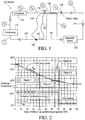
- the system 110 comprises a vapor cycle refrigeration system having a conventional compressor 112 which feeds a high pressure, high temperature output as a pressurized gas to a condenser 114.
- the condenser 114 reduces the refrigerant temperature to a primarily liquid state at ambient or near ambient temperature.
- the condenser 114 may be liquid or air cooled, and may use a regulated coolant control or be unregulated.
- the liquefied pressurized product from the condenser 114 is input to an externally equalized thermal expansion valve (hereafter TXV) 119.
- TXV 119 has a conventional internal diaphragm (not shown) whose position determines the amount of flow through TXV 119.
- the TXV 119 diaphragm position is responsive to the difference in pressures between the input line 124, communicated to TXV 119 through the line 133, to compressor 112 and that of the pressure of a liquid contained in a closed volume bulb 122 communicated through a tubing line 120.
- Bulb 122 is placed in close thermal communication with input line 124 at or near the point 136 at which pressure in input line 124 is measured to communicate with said diaphragm in TXV 119.
- the TXV 119 uses the difference between these pressures to open and close the TXV 119 to provide the maximum amount of cooling at the lowest achievable temperature.
- the expanded output of TXV 119 is delivered at point T 6 as one input to a subsidiary HEX 126 in the refrigerant path leading to the evaporator, which is the load 130.
- the expanded fluid from the TXV flows in heat exchange relation with returned refrigerant at point (T 9 ) from the system load (evaporator) 130 that ultimately feeds the suction input line 124 to the compressor 112.
- This return line from the load 130 through the HEX 126 to the compressor 112 input therefore forms part of a subsidiary heat exchange loop configured and operated to provide improved heat transfer.
- the outflow from the TXV 119 at point (T 6 ) first passes through HEX 126 a stabilizing flow impedance.
- the latter thus introduces a temperature drop somewhat greater than the maximum superheat used to regulate the cooling temperature with the TXV 119 or other expansion device that is used.
- the stabilizing impedance advantageously comprises a differential or delta pressure ( ⁇ P) valve 132, which provides a controlled pressure drop.
- the ⁇ P valve 132 here induces a temperature drop that approximates the difference between the evaporating refrigerant and the load being cooled, since the evaporator 130 superheat is a factor critical to stable operation.
- the system of Fig. 1 provides the basic compression and condensation functions of a vapor cycle system, feeding the liquefied, pressurized refrigerant to the TXV 119, which then controls the expansion, consequently the major amount of cooling, of the refrigerant, at point (T 6 ) of Fig. 1 .
- a capillary having a fixed aperture and pressure drop may alternatively be used, but the TXV 119 is more functional in systems which are designed for high efficiency.
- Fig. 1 also depicts a standard vapor cycle without EPC. If the flow out of load 130 were to pass through line 135, shown in dashed form, said flow would bypass EPC HEX 126 and flow directly to compressor 112. In this case the valve 132 would not serve any particular purpose. It would simply be a part of the impedance of TXV 119. The system would then function exactly as a standard vapor-cycle cooling system.
- thermodynamic cycle undergoes a fundamental variation from the usual cycle, exchanging thermal energy between the return flow from and the input flow to the evaporator 130.
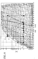
- Fig. 5 which comprises a Mollier diagram showing exchange between flow in the return line from the evaporator or load 130 points (T 9 ) to (T 1 ) and input flow from the TXV 119, at points (T 6 ) to (T 7 ), to the evaporator 130.
- the input flow temperature is then dropped as refrigerant passes through the adjacent ⁇ P valve 132.
- this subsidiary heat exchange loop as seen in the pressure vs. enthalpy Mollier diagram of Fig.
- the thermal energy exchange between points (T 6 ) and (T 7 ) on the outgoing flow and points (T 9 ) to (T 1 ) in the return flow is effectively substantially equal.
- the refrigerant in boiling its liquid from T 9 to T 1 provides enough cooling to condense liquid on the other side of HEX 126 to reduce the enthalpy of the input refrigerant from T 6 to T 7 .
- This heat transfer is driven by the temperature difference from T 7,6 to T 9,1 .
- This temperature difference is created by the effect of pressure dropping valve 132.
- the pressure drop in the ⁇ P valve 132 lowers the temperature.
- the combined effect of the HEX 126 and the ⁇ P valve 132 reduces the quality (vapor mass percentage to total mass percentage) of the refrigerant that is delivered to the load 130.
- Fig. 2 a practical consideration in the design of an economically justifiable evaporator is that the conventional evaporator utilizes a relatively economical construction based on constant cross-sectional area for the majority of its length. Heat transfer in such a passage, for different spans of regions along the evaporator length, is as depicted in Fig. 2 .
- the h is dependent on the maximum mass velocity per unit cross-section area, and also on the "quality" of the mixture of vapor and liquid.
- the temperature difference between one flow and the opposite flow in the supplemental HEX is, as noted above, set by the pressure dropping valve 132.
- This temperature difference is typically set at about the same difference between the boiling temperature of the two phase fluid in load 130 and the temperature of the pure gas as it goes to the input of compressor 112. This temperature difference is called the evaporator "superheat" and in practice varies from about 3°C to about 15°C.
- the TXV 119 plays a significant role in the measurement of superheat because the pressure difference across the TXV 119 diaphragm controls the degree of opening of the TXV 119.
- the pressure difference would be about 3.3 bar (about 50 psi) and would represent a wide open valve. If the pressure difference approaches zero bar, and the superheat approaches zero, the TXV 119 would be shut, or nearly so.
- the fluid filling the sensing bulb 122 coupled to the TXV 119 is chosen to have a vapor pressure similar to, but not necessarily identical to, that of the refrigerant used in the cooling cycle.
- the pressure drop in the post condensation step from point (T 6 ) to point (T 8 ) is selected to introduce a temperature change approximately the same as the superheat used to regulate the cooling temperature.
- Figs. 3 and 4 also show how h varies with the changing dynamics of the refrigerant, its velocity and quality.
- Fig. 3h is plotted against heat transfer values for different "leaving vapor fractions”
- Fig. 4 the variation of h is plotted against the length of the evaporator in relation to the four regions identified in Fig. 2 .
- Figs. 2-4 show clearly that the h drops by more than 50%, as the dry end of the evaporator is approached. This unbroken decline is a result of the status of the refrigerant mass as its vapor/liquid ratio changes, and is not economically resolvable by practical design expedients in the evaporator.
- a so-called flooded evaporator is used in those applications wherein the weight and size of the evaporator is a significant design parameter.
- the superheat in the evaporator is held to zero.
- the lack of efficiency is less desirable at present time than in the past due to the looming energy shortage.
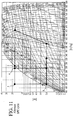
- Fig. 10 shows a block diagram of an EPC system that is different than that of Fig. 1 in that subsidiary HEX 126 is located in the flow of refrigerant before TXV 119 rather than after.
- This system offers the advantage that the temperature difference across EPC HEX 126 is greater and the use of pressure differential valve 132 is not needed.
- HEX 126 must be run in parallel flow in this system for proper stability to be achieved. It is also possible to run the system of Fig. 10 with a TXV that is internally equalized since there can potentially be only a small pressure drop in the circuit from TXV 119 to the location of bulb 122 in line 124.
- Fig. 11 shows a Mollier diagram of the system shown in Fig. 10 .
- This graph shows the effectiveness of the EPC concept a just as did Fig. 5 for the system of Fig. 1 .
- the expansion from T 4 to T 5 would leave the heat transfer in load 130 boiling a mix from 45% quality to a superheat of 5°C. This would cause the same problems of heat transfer as discussed in the case of the system of Fig. 1 .
- the boiling from T 8 to T 9 changes the mix from a quality of 5% to 65%. This clearly increases the heat transfer effectiveness of the HEX in load 130 in the same manner as with the system of Fig. 1 .
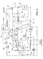
- a temperature control system of the TDSF type corresponds to that disclosed in patent US 7,178,353 but includes an enhanced post condensation (EPC) variant, without altering the basic operative characteristics of the TDSF system.
- EPC enhanced post condensation
- a two-phase refrigerant medium is pressurized in a conventional compressor 112, and its output is divided into two paths, one of which is directed to a condenser 114.
- the condenser 114 is shown with an external HEX 615 which receives flow from a conventional source, here from a facility water source 616.
- the flow is regulated by a valve 617 that may be controlled manually or automatically to maintain the output from the condenser 114 at a selected level.
- One flow path from the compressor 112 is a first liquid/vapor path 618, through the condenser 114 and feeding a thermo-expansion valve (TXV) 119.
- the second flow path from the compressor 112 proceeds from a branch point and comprises a hot gas line 624 which feeds a proportional valve 625.
- the proportional valve 625 operates under control of a system controller 631, and the two lines 618, 624 feed into a mixing mechanism or circuit 633.
- the flow in the hot gas line 624 goes from the proportional valve 625 through a check valve 632 to one input of a mixing tee 640.
- the other input to the mixing tee 640 is applied via a ⁇ p valve 132 which receives flow passing through the TXV 119, and drops the pressure and temperature in that line by a predetermined amount.
- thermo-expansion valve 119 is externally equalized by pressure input from the return line 124 in the region near bulb 122 in thermal communication with the return line 124 to the compressor 112 via a line 120.
- the TXV 119 is equalized via a pressure tap through a line 133 from outlet line 124.
- TXV 119 It is necessary that the TXV 119 be externally equalized thusly in all EPC systems of the type shown in Fig. 1 using a TXV. There must be a large pressure difference between the TXV 119 and the location of the bulb 122. This is due to the pressure difference established by differential pressure valve 132. TXVs that are internally equalized measure the difference between the bulb pressure and the pressure at the outlet of the TXV. If a larger than nominal pressure difference exists between the TXV and the circuit near bulb 122, the TXV must be externally equalized. This is clearly the case with the EPC system shown in Fig. 1 .
- the return flow also passes through a close-on-rise (CRO) regulator 650, which regulator limits the pressure fed to compressor 112 within design limits.
- the flow rate is kept within acceptable temperature limits by a branch line that contains a desuperheater valve (DSV) 652 between the output from the condenser 114 and the input to the compressor 112.
- CRO close
- the desuperheater valve 652 receives a pressure input from a bulb 654 adjacent the compressor 112 input.
- a heater 656 responsive to the controller 631 is included to assure that the compressor 112 does not receive an input containing liquid components.
- Further operative stability is derived by incorporating a hot gas bypass valve 659 in a feedback line between the compressor 112 output and its input.
- the input line to the load 630' from the mixing mechanism 633 which includes a tee 640, goes through one side of an EPC HEX 126 and then through a ⁇ p valve 132 before being applied to the load 630'.
- Return flow from the load 630' toward the compressor 112 passes through the opposite side of the HEX 126 before ultimately reaching the compressor 112 via the interposed valves and devices.
- a shunt line 664 as a bypass from a point between the hot gas line 624 after the proportional valve 625.
- the bypass line 664 includes a solenoid valve (SXV) 663 and an orifice 662.
- SXV solenoid valve
- the controller 631 opens the SXV 663 to effectively severely diminish the hot gas flow to mixing tee 640 so that the cooled expanded flow from the line 672 solely determines the operating temperature.
- the TDSF alters the temperature by introducing a heat load from the hot gas at point 2. This controls the temperature at load 630' as explained below. As stated, the TDSF adds a heat load to adjust the temperature.
- the heat load that can be cooled by a standard cycle is represented by the enthalpy change from point 5 to point 1.
- the cooling potential from point 5 to point 1 is excessive. If there were to be no added heat load the cycle would cool load 630' below the temperature shown and temperature control would thus be lacking.
- the TDSF system adds a heat load by combining an appropriate amount of hot gas from point 2 expanded to point 2 T0 with the mix at point 8 so that the result is a mix at point 5 T0 .
- the system and heat load 630' would be in balance at the correct regulated temperature.
- the EPC system overcomes this problem.
- the EPC system mixes hot gas expanded to point 2 T0 with the output of the valve 132. In this case the resultant mix is combined at point 8 T0 .
- the mix then boils off in cooling the load 630' to point 9.
- the mix then enters the exit side of the HEX 126 in post condensing the mix on the input side of the HEX as well as cooling any losses incidental to the process.
- the outgoing fluid heats from point 9 to point 1 in the process of cooling the incoming fluid from point 6 to point 7.
- the fact that the h is low in the final stages of this process is of no consequence to the load 630' temperature.
- the enhanced post condensing elements in the system of Fig. 6 comprise the HEX 126 (or EPC HEX) and the pressure dropping valve (or EPC valve) 132.
- EPC HEX EPC HEX
- One side of this HEX 126 is in the direct path from the mixing tee 640 to the load 630' input, and the path on the other side of the exchanger 126 receives the output flow from the load 630', and returns it ultimately to the compressor 112. While providing functions equivalent to those described previously in the EPC example of Fig. 1 in the TDSF system this also provides operative capabilities unique to the dual flow dynamic of the TDSF system and the asymmetries that can arise therefrom.
- the effect of the EPC on the TDSF system is particularly beneficial in the case of temperature regulation of a load under very low or essentially zero load. If a load is being controlled with a system capable of cooling or heating several kilowatts (kw) it is very difficult to effect precise control when there is little or no load externally imposed. This is a common case in the Semiconductor industry. A system can be called on to absorb or supply 1-3 kw of heat with a precision that ensures a load temperature within ⁇ 1°C. It can also be required to maintain the same load at temperature under conditions during which almost no load is being supplied. This is difficult with any temperature control system. The TDSF system has an especially difficult time with the zero or no load case because of the details of heat transfer within the TDSF system. Basically, the problem is that liquid condensing hs are orders of magnitude higher than those encountered with gas transferring sensible heat.
- Fig. 8 illustrates the problem. If the load power to be controlled is at or near zero the mixing of hot gas expanded to point 2' T0 with the mix at 8' would result in a mixture at 8" T0 without EPC. As controller 631 makes small adjustments for the purpose of keeping the load at the set temperature under dynamic conditions the control mixture will vary between points such as 8" 0H to 8" 0C . (The movement of the control points has been exaggerated for clarity. The actual movement would generally be about a 1/3 of that shown in Fig. 8 .) A small error on the hot side would move the mixture point very far from the control point desired. This is because a large amount of heat power (e.g.
- FIG. 9 A practical example of efficiency improvement achieved in an existing air cooling system is provided by a 7000 BTU/hr air cooler used in commercial passenger aircraft to chill food transported along the passenger compartment in mobile service carts.
- the system operates with R134a refrigerant kept between 50°C condensing and 5°C evaporating temperature.
- the illustrative system referring now to Fig. 9 , is set up with a switchable bypass for objective tests as shown in the generalized schematic perspective to compare an existing refrigeration system with one using enhanced post condensation in accordance with the invention. In this test system of Fig.
- the cycling gaseous refrigerant was pressurized by the compressor 112 from about 12°C and 6 bar pressure to a pressure of about 20 bar at 90°C, and the refrigerant was then cooled by the condenser 114 to a liquid, at approximately ambient temperature and high pressure.
- the refrigerant was expanded to a mixture of liquid and gas at a lower temperature and pressure, here approximately 5°C and 6 bar, and then delivered to the load evaporator 630'.
- the load 630' comprises in this practical example a portable cart 1180 containing cooled or refrigerated comestibles such as drinks, desserts, sandwiches (not shown) all within the cart and exterior to the base unit.
- Air movement through the base unit and cart 1180 is facilitated by a blower 1182 behind the evaporator 630', since the flow impedance within the cart 1180 can be considerable and thermal energy interchanged in the evaporator with cooled refrigerant is to be transferred from the counter-current refrigerant flow to an ultimately external air flow to the cart 1180.
- the refrigerant, as pure gas, transferred back from the evaporator 630' to the suction input of the compressor 112 is at a temperature slightly warmer than the boiling temperature within the evaporator 630'. Compression is again applied as the cycle is repeated.
- the known, widely used, exemplification of this system generates 7000 BTU, but since the system is airborne and intended for passenger service, improvement in efficiency can have significant benefits in enabling size and weight
- the refrigeration loop was modified by incorporating the relatively small HEX 126.
- the separate internal loop was accessible by a switchable bypass 1186 after the TXV 119, so that refrigerant flowed to the smaller counter-current HEX 126 (solid line) instead of directly to the load. Then the flow was through the ⁇ P valve 132 and into the load 630'. On the return path to the suction input to the compressor 112, the refrigerant counter flowed through the HEX 126 with relatively low pressure drop, and then returned to the suction input to the compressor 112.
Landscapes
- Engineering & Computer Science (AREA)
- Physics & Mathematics (AREA)
- Mechanical Engineering (AREA)
- Thermal Sciences (AREA)
- General Engineering & Computer Science (AREA)
- Compression-Type Refrigeration Machines With Reversible Cycles (AREA)
- Air Conditioning Control Device (AREA)
Claims (9)
- Wärmesteuersystem, das ein Kühlmittel verwendet und einen Kühlkreislauf mit mehreren operativen Elementen aufweist, umfassend einen Verdichter (112), einen Kondensator (114) und eine Expansionsvorrichtung (119) in Folgeschaltung, in thermischer Verbindung mit einem die zu kühlende Last aufweisenden Verdampfer (130), wobei der Verdampfer (130) einen nichtlinearen Wärmeübertragungskoeffizienten in Abhängigkeit von lokalisierten Kühlmittelqualitätsvariationen aufweist, wobei Qualität als das Verhältnis Flüssigkeit zu Dampf ausgedrückt wird, wobei ein Hilfswärmetauschkreis zwischen der Expansionsvorrichtung (119) und dem Verdampfer (130) angeordnet ist und einen Gegenstrom-Wärmetauscher (126) aufweist, der die Expansionsvorrichtung mit dem Verdampfer (130) auf der einen Seite und den Ausgang vom Verdampfer (130) mit dem Verdichter (112) auf der anderen Seite verbindet, der Kühlkreis ferner eine Differenzdruckvorrichtung (132) zwischen dem Gegenstrom-Wärmetauscher (126) und dem Verdampfer (130) aufweist, gekennzeichnet durch:die Differenzdruckvorrichtung (132) die Überhitzungswärme des Hilfskühlkreises in einem ausgewählten Bereich aufrechterhält,die Differenzdruckvorrichtung (132) in der Leitung zwischen dem Ausgang vom Gegenstrom-Wärmetauscher (126) und dem Eingang des Verdampfers (130) die Temperaturdifferenz zwischen einem Durchfluss und dem entgegengesetzten Durchfluss im Gegenstrom-Wärmetauscher (126) einstellt, wobei die Temperaturdifferenz auf ungefähr die gleiche Differenz zwischen der Siedetemperatur des Zwei-Phasen-Durchflusses im Verdampfer (130) und der Temperatur des reinen Gases bei dessen Strömung zum Eingang des Verdichters (112) eingestellt wird.
- Wärmesteuersystem nach Anspruch 1, wobei die Änderung des Druckes über die Differenzdruckvorrichtung (132) eine Temperaturänderung über die Vorrichtung einführt, die die Temperaturdifferenz zwischen dem verdampfenden Kühlmittel und der Last, die gekühlt wird, angleicht.
- Wärmesteuersystem nach Anspruch 1, wobei der Kühlkreislauf eine Thermo-Expansionsvorrichtung aufweist, die einen Dampf begrenzenden Kontaktfühler (122) umfasst, der auf die Temperatur des vom Wärmetauscher (126) an den Verdichter (112) zurückgeleiteten Kühlmittels anspricht, wobei die innere Flüssigkeit des Kontaktfühlers (122) ausgewählt ist, um einen gewählten Dampfdruck zum Angleichen an das im Kühlkreislauf verwendete Kühlmittel aufzuweisen.
- Wärmesteuersystem nach Anspruch 1, wobei die Differenzdruckvorrichtung (132) in der Leitung zwischen dem Ausgang vom Hilfswärmetausch und dem Eingang zum Verdampfer (130) eingestellt ist, um eine Temperaturänderung bereitzustellen, die die Überhitzungswärme des Verdampfers (130) angleicht.
- Wärmesteuersystem nach Anspruch 1, wobei das Kühlsystem ein System zum Vermischen von Kühlmittel in expandierter mindestens teilweiser Dampfphase nach Kondensation mit dem gleichen Kühlmittel in Druckgasphase umfasst, einschließlich einem Mechanismus zum Vermischen der zwei verschiedenen Phasen für Anwenden auf einen Verdampfer von vorgegebener thermischer Kapazität, wobei der Hilfswärmetauscherkreis zwischen dem Mischmechanismus und dem Verdampfer (130) angeordnet ist.
- Wärmesteuersystem nach Anspruch 1, wobei die Druckgasphase einen wesentlich höheren Energiegehalt als die expandierte Dampfphase hat, und wobei der Hilfswärmetauscherkreis das gesamte Wärmesteuersystem stabilisiert, um relativ kleine inkrementelle Temperaturänderungen zu bewirken.
- Wärmesteuersystem nach Anspruch 1, wobei der Gegenstrom-Wärmetauscher (126) eine geringere thermische Kapazität aufweist als die bekannte thermische Kapazität des Lastverdampfers (130).
- Wärmesteuersystem nach Anspruch 1, wobei die Temperaturdifferenz von 3 °C bis ungefähr 15 °C variiert.
- Wärmesteuersystem nach Anspruch 1, wobei die Expansionsvorrichtung (119) ein Thermo-Expansionsventil (119) umfasst, das durch Druckeingang von der Rücklaufleitung (124) zum Verdichter (112) extern ausgeglichen wird.
Applications Claiming Priority (3)
| Application Number | Priority Date | Filing Date | Title |
|---|---|---|---|
| US99809307P | 2007-10-09 | 2007-10-09 | |
| US1186208P | 2008-01-22 | 2008-01-22 | |
| PCT/US2008/079424 WO2009049096A1 (en) | 2007-10-09 | 2008-10-09 | Thermal control system and method |
Publications (3)
| Publication Number | Publication Date |
|---|---|
| EP2198217A1 EP2198217A1 (de) | 2010-06-23 |
| EP2198217A4 EP2198217A4 (de) | 2014-04-09 |
| EP2198217B1 true EP2198217B1 (de) | 2017-05-10 |
Family
ID=40549569
Family Applications (1)
| Application Number | Title | Priority Date | Filing Date |
|---|---|---|---|
| EP08837303.0A Not-in-force EP2198217B1 (de) | 2007-10-09 | 2008-10-09 | Wärmesteuersystem |
Country Status (6)
| Country | Link |
|---|---|
| US (2) | US8291719B2 (de) |
| EP (1) | EP2198217B1 (de) |
| JP (1) | JP5473922B2 (de) |
| KR (1) | KR101460222B1 (de) |
| CA (1) | CA2702068C (de) |
| WO (1) | WO2009049096A1 (de) |
Families Citing this family (28)
| Publication number | Priority date | Publication date | Assignee | Title |
|---|---|---|---|---|
| US8532832B2 (en) * | 2008-09-23 | 2013-09-10 | Be Aerospace, Inc. | Method and apparatus for thermal exchange with two-phase media |
| FR2956730B1 (fr) * | 2010-02-25 | 2012-04-06 | Air Liquide | Procede de refroidissement cryogenique utilisant un ecoulement de co2 diphasique solide-gaz |
| WO2011130162A2 (en) | 2010-04-12 | 2011-10-20 | Drexel University | Heat pump water heater |
| US20120000240A1 (en) * | 2010-07-01 | 2012-01-05 | Brent Alden Junge | Refrigerant cooling device |
| US9360243B1 (en) * | 2010-07-14 | 2016-06-07 | B/E Aerospace, Inc. | Temperature control system and method TDSF plus |
| EP2468945B1 (de) * | 2010-12-27 | 2019-04-17 | Electrolux Home Products Corporation N.V. | Haushaltswäschetrockner mit Wärmepumpe |
| EP2468944B1 (de) * | 2010-12-27 | 2019-02-20 | Electrolux Home Products Corporation N.V. | Haushaltswäschetrockner mit Wärmepumpe |
| GB201102971D0 (en) * | 2011-02-21 | 2011-04-06 | Strix Ltd | Electrical water heating appliances |
| US8931288B2 (en) * | 2012-10-19 | 2015-01-13 | Lennox Industries Inc. | Pressure regulation of an air conditioner |
| US10168086B2 (en) * | 2013-07-12 | 2019-01-01 | B/E Aerospace, Inc. | Temperature control system with programmable ORIT valve |
| KR101624081B1 (ko) * | 2014-06-10 | 2016-05-24 | 주식회사 엘지화학 | 열 회수 장치 |
| MX2016016776A (es) * | 2014-07-01 | 2017-05-17 | Evapco Inc | Precalentador de liquido de evaporador para la reduccion de carga de refrigerante. |
| CN104132487B (zh) * | 2014-07-24 | 2017-01-18 | 康特能源科技(苏州)有限公司 | 双压控制的空气源热泵系统 |
| WO2016027116A1 (en) * | 2014-08-21 | 2016-02-25 | Carrier Corporation | Improved direct expansion evaporator based chiller system |
| US10041860B2 (en) * | 2015-01-30 | 2018-08-07 | Haier Us Appliance Solutions, Inc. | Method for detecting a faulty air handler in a heat pump appliance |
| KR101978751B1 (ko) * | 2017-10-27 | 2019-05-15 | 오텍캐리어 주식회사 | 한랭지용 이원냉동사이클을 이용한 히트펌프 시스템 |
| JP7101023B2 (ja) * | 2018-04-03 | 2022-07-14 | 東京エレクトロン株式会社 | 温調方法 |
| JP7094131B2 (ja) | 2018-04-03 | 2022-07-01 | 東京エレクトロン株式会社 | クリーニング方法 |
| JP2020043171A (ja) | 2018-09-07 | 2020-03-19 | 東京エレクトロン株式会社 | 温調方法 |
| JP7112915B2 (ja) | 2018-09-07 | 2022-08-04 | 東京エレクトロン株式会社 | 温調システム |
| FR3089604B1 (fr) * | 2018-12-05 | 2021-04-02 | Valeo Systemes Thermiques | Systeme de conditionnement thermique d’un vehicule |
| WO2020115444A2 (fr) * | 2018-12-05 | 2020-06-11 | Valeo Systemes Thermiques | Systeme de conditionnement thermique d'un vehicule |
| WO2020217800A1 (ja) * | 2019-04-23 | 2020-10-29 | Ckd株式会社 | 熱交換システム |
| SE2050095A1 (en) * | 2020-01-30 | 2021-07-31 | Swep Int Ab | A refrigeration system |
| SE545516C2 (en) * | 2020-01-30 | 2023-10-03 | Swep Int Ab | A refrigeration system and method for controlling such a refrigeration system |
| US11988427B2 (en) | 2021-04-29 | 2024-05-21 | Vertiv Corporation | Refrigerant cold start system |
| KR20220165415A (ko) * | 2021-06-08 | 2022-12-15 | 현대자동차주식회사 | 에어모빌리티의 실내 승압 시스템 |
| US20240200833A1 (en) * | 2022-12-14 | 2024-06-20 | Icebox Heat Pumps Inc. | Systems and methods of heating and cooling cycle with isochoric heating |
Family Cites Families (39)
| Publication number | Priority date | Publication date | Assignee | Title |
|---|---|---|---|---|
| US3852974A (en) * | 1971-12-03 | 1974-12-10 | T Brown | Refrigeration system with subcooler |
| US4032070A (en) * | 1974-08-07 | 1977-06-28 | Danfoss A/S | Thermostatic expansion valve for refrigeration installations |
| US4438881A (en) * | 1981-01-27 | 1984-03-27 | Pendergrass Joseph C | Solar assisted heat pump heating system |
| JPH02166367A (ja) * | 1988-12-19 | 1990-06-27 | Fuji Koki Seisakusho:Kk | 温度膨張弁 |
| JP3301100B2 (ja) * | 1991-01-31 | 2002-07-15 | 株式会社デンソー | 蒸発器および冷凍サイクル装置 |
| US5095712A (en) * | 1991-05-03 | 1992-03-17 | Carrier Corporation | Economizer control with variable capacity |
| US5245833A (en) * | 1992-05-19 | 1993-09-21 | Martin Marietta Energy Systems, Inc. | Liquid over-feeding air conditioning system and method |
| US5426952A (en) * | 1994-03-03 | 1995-06-27 | General Electric Company | Refrigerant flow rate control based on evaporator exit dryness |
| JPH0875290A (ja) * | 1994-09-06 | 1996-03-19 | Hitachi Ltd | ヒートポンプ式空調装置 |
| DE69636207T2 (de) * | 1995-03-14 | 2007-04-05 | Hussmann Corp. | Verkaufsmöbel mit modularen Verdampferrohrschlangen und elektronischer Steuerung der Verdampfdruckregelung |
| US5622055A (en) * | 1995-03-22 | 1997-04-22 | Martin Marietta Energy Systems, Inc. | Liquid over-feeding refrigeration system and method with integrated accumulator-expander-heat exchanger |
| JP3484866B2 (ja) * | 1995-08-04 | 2004-01-06 | 三菱電機株式会社 | 冷凍装置 |
| JPH09152204A (ja) * | 1995-11-30 | 1997-06-10 | Toshiba Corp | 冷凍サイクル |
| US5845502A (en) * | 1996-07-22 | 1998-12-08 | Lockheed Martin Energy Research Corporation | Heat pump having improved defrost system |
| US5899091A (en) * | 1997-12-15 | 1999-05-04 | Carrier Corporation | Refrigeration system with integrated economizer/oil cooler |
| JP2000346472A (ja) * | 1999-06-08 | 2000-12-15 | Mitsubishi Heavy Ind Ltd | 超臨界蒸気圧縮サイクル |
| JP4323619B2 (ja) * | 1999-06-17 | 2009-09-02 | 株式会社日本クライメイトシステムズ | 車両用空調装置 |
| US6233958B1 (en) * | 1999-09-15 | 2001-05-22 | Lockhead Martin Energy Research Corp. | Heat pump water heater and method of making the same |
| JP2002195677A (ja) * | 2000-10-20 | 2002-07-10 | Denso Corp | ヒートポンプサイクル |
| JP3693562B2 (ja) * | 2000-10-23 | 2005-09-07 | 松下エコシステムズ株式会社 | 冷凍サイクル装置及び冷凍サイクルの制御方法 |
| JP2002130849A (ja) * | 2000-10-30 | 2002-05-09 | Calsonic Kansei Corp | 冷房サイクルおよびその制御方法 |
| US6460358B1 (en) * | 2000-11-13 | 2002-10-08 | Thomas H. Hebert | Flash gas and superheat eliminator for evaporators and method therefor |
| JP3801006B2 (ja) * | 2001-06-11 | 2006-07-26 | ダイキン工業株式会社 | 冷媒回路 |
| US6564563B2 (en) * | 2001-06-29 | 2003-05-20 | International Business Machines Corporation | Logic module refrigeration system with condensation control |
| JP3811116B2 (ja) * | 2001-10-19 | 2006-08-16 | 松下電器産業株式会社 | 冷凍サイクル装置 |
| US6925822B2 (en) * | 2003-12-10 | 2005-08-09 | Carrier Corporation | Oil return control in refrigerant system |
| US7131294B2 (en) * | 2004-01-13 | 2006-11-07 | Tecumseh Products Company | Method and apparatus for control of carbon dioxide gas cooler pressure by use of a capillary tube |
| TWI332073B (en) * | 2004-02-12 | 2010-10-21 | Sanyo Electric Co | Heating/cooling system |
| US7178353B2 (en) * | 2004-02-19 | 2007-02-20 | Advanced Thermal Sciences Corp. | Thermal control system and method |
| US7377126B2 (en) * | 2004-07-14 | 2008-05-27 | Carrier Corporation | Refrigeration system |
| US7059151B2 (en) * | 2004-07-15 | 2006-06-13 | Carrier Corporation | Refrigerant systems with reheat and economizer |
| US20060042274A1 (en) * | 2004-08-27 | 2006-03-02 | Manole Dan M | Refrigeration system and a method for reducing the charge of refrigerant there in |
| JP4459776B2 (ja) * | 2004-10-18 | 2010-04-28 | 三菱電機株式会社 | ヒートポンプ装置及びヒートポンプ装置の室外機 |
| US7325414B2 (en) * | 2004-10-28 | 2008-02-05 | Carrier Corporation | Hybrid tandem compressor system with economizer circuit and reheat function for multi-level cooling |
| JP3982545B2 (ja) * | 2005-09-22 | 2007-09-26 | ダイキン工業株式会社 | 空気調和装置 |
| US20070095087A1 (en) * | 2005-11-01 | 2007-05-03 | Wilson Michael J | Vapor compression cooling system for cooling electronics |
| JP2007139225A (ja) * | 2005-11-15 | 2007-06-07 | Hitachi Ltd | 冷凍装置 |
| JP2007155229A (ja) * | 2005-12-06 | 2007-06-21 | Sanden Corp | 蒸気圧縮式冷凍サイクル |
| US7335983B2 (en) * | 2005-12-16 | 2008-02-26 | Intel Corporation | Carbon nanotube micro-chimney and thermo siphon die-level cooling |
-
2008
- 2008-10-09 US US12/285,596 patent/US8291719B2/en active Active
- 2008-10-09 EP EP08837303.0A patent/EP2198217B1/de not_active Not-in-force
- 2008-10-09 WO PCT/US2008/079424 patent/WO2009049096A1/en active Application Filing
- 2008-10-09 CA CA2702068A patent/CA2702068C/en not_active Expired - Fee Related
- 2008-10-09 KR KR1020107010052A patent/KR101460222B1/ko active IP Right Grant
- 2008-10-09 JP JP2010529058A patent/JP5473922B2/ja not_active Expired - Fee Related
-
2012
- 2012-10-15 US US13/651,631 patent/US8689575B2/en active Active
Also Published As
| Publication number | Publication date |
|---|---|
| KR101460222B1 (ko) | 2014-11-10 |
| CA2702068C (en) | 2015-06-23 |
| JP2011501092A (ja) | 2011-01-06 |
| WO2009049096A1 (en) | 2009-04-16 |
| CA2702068A1 (en) | 2009-04-16 |
| EP2198217A4 (de) | 2014-04-09 |
| KR20100080551A (ko) | 2010-07-08 |
| EP2198217A1 (de) | 2010-06-23 |
| JP5473922B2 (ja) | 2014-04-16 |
| US20090105889A1 (en) | 2009-04-23 |
| US20130036753A1 (en) | 2013-02-14 |
| US8291719B2 (en) | 2012-10-23 |
| US8689575B2 (en) | 2014-04-08 |
Similar Documents
| Publication | Publication Date | Title |
|---|---|---|
| EP2198217B1 (de) | Wärmesteuersystem | |
| US11378314B2 (en) | Air cooled chiller with heat recovery | |
| US6460355B1 (en) | Environmental test chamber fast cool down and heat up system | |
| JP5581300B2 (ja) | 熱制御方法及びそのシステム | |
| KR100856991B1 (ko) | 냉동 공조장치, 냉동 공조장치의 운전 제어 방법, 냉동공조장치의 냉매량 제어 방법 | |
| US7997092B2 (en) | Refrigerant vapor compression system operating at or near zero load | |
| US6827142B2 (en) | Process and apparatus for achieving precision temperature control | |
| DK2147264T3 (en) | Refrigerant vapor compression system | |
| US20100251750A1 (en) | Economized refrigerant system with flow control | |
| JP2011501092A5 (de) | ||
| CN105378399B (zh) | 带有可编程orit阀的温度控制系统 | |
| US8240160B2 (en) | Thermal control system and method | |
| US3952533A (en) | Multiple valve refrigeration system | |
| CN101344341A (zh) | 冷冻装置 | |
| JP2003130428A (ja) | 連結型冷温水装置 | |
| JP2007017093A (ja) | 冷凍装置 | |
| KR102561069B1 (ko) | 브라인 칠러 및 이를 포함하는 이산화탄소 복합 사이클 시스템 | |
| US20230070076A1 (en) | Enhanced air conditioning chiller system | |
| CN118168179A (zh) | 复叠制冷系统及控制方法 | |
| CN118310184A (zh) | 半导体温控设备及温控方法 | |
| JPH0882449A (ja) | 冷凍機の温度制御装置 |
Legal Events
| Date | Code | Title | Description |
|---|---|---|---|
| PUAI | Public reference made under article 153(3) epc to a published international application that has entered the european phase |
Free format text: ORIGINAL CODE: 0009012 |
|
| 17P | Request for examination filed |
Effective date: 20100331 |
|
| AK | Designated contracting states |
Kind code of ref document: A1 Designated state(s): AT BE BG CH CY CZ DE DK EE ES FI FR GB GR HR HU IE IS IT LI LT LU LV MC MT NL NO PL PT RO SE SI SK TR |
|
| AX | Request for extension of the european patent |
Extension state: AL BA MK RS |
|
| RIN1 | Information on inventor provided before grant (corrected) |
Inventor name: ZUBILLAGA, GLENN, W. Inventor name: COWANS, WILLIAM, W. Inventor name: COWANS, KENNETH, W. |
|
| DAX | Request for extension of the european patent (deleted) | ||
| RAP1 | Party data changed (applicant data changed or rights of an application transferred) |
Owner name: BE AEROSPACE, INC. |
|
| REG | Reference to a national code |
Ref country code: DE Ref legal event code: R079 Ref document number: 602008050250 Country of ref document: DE Free format text: PREVIOUS MAIN CLASS: F25B0041000000 Ipc: F25B0040000000 |
|
| A4 | Supplementary search report drawn up and despatched |
Effective date: 20140307 |
|
| RIC1 | Information provided on ipc code assigned before grant |
Ipc: F25B 40/00 20060101AFI20140303BHEP |
|
| 17Q | First examination report despatched |
Effective date: 20160518 |
|
| GRAP | Despatch of communication of intention to grant a patent |
Free format text: ORIGINAL CODE: EPIDOSNIGR1 |
|
| INTG | Intention to grant announced |
Effective date: 20161215 |
|
| GRAS | Grant fee paid |
Free format text: ORIGINAL CODE: EPIDOSNIGR3 |
|
| GRAA | (expected) grant |
Free format text: ORIGINAL CODE: 0009210 |
|
| AK | Designated contracting states |
Kind code of ref document: B1 Designated state(s): AT BE BG CH CY CZ DE DK EE ES FI FR GB GR HR HU IE IS IT LI LT LU LV MC MT NL NO PL PT RO SE SI SK TR |
|
| REG | Reference to a national code |
Ref country code: GB Ref legal event code: FG4D |
|
| REG | Reference to a national code |
Ref country code: AT Ref legal event code: REF Ref document number: 892797 Country of ref document: AT Kind code of ref document: T Effective date: 20170515 Ref country code: CH Ref legal event code: EP |
|
| REG | Reference to a national code |
Ref country code: IE Ref legal event code: FG4D |
|
| REG | Reference to a national code |
Ref country code: DE Ref legal event code: R096 Ref document number: 602008050250 Country of ref document: DE |
|
| REG | Reference to a national code |
Ref country code: NL Ref legal event code: MP Effective date: 20170510 |
|
| REG | Reference to a national code |
Ref country code: LT Ref legal event code: MG4D |
|
| REG | Reference to a national code |
Ref country code: AT Ref legal event code: MK05 Ref document number: 892797 Country of ref document: AT Kind code of ref document: T Effective date: 20170510 |
|
| REG | Reference to a national code |
Ref country code: FR Ref legal event code: PLFP Year of fee payment: 10 |
|
| PG25 | Lapsed in a contracting state [announced via postgrant information from national office to epo] |
Ref country code: ES Free format text: LAPSE BECAUSE OF FAILURE TO SUBMIT A TRANSLATION OF THE DESCRIPTION OR TO PAY THE FEE WITHIN THE PRESCRIBED TIME-LIMIT Effective date: 20170510 Ref country code: HR Free format text: LAPSE BECAUSE OF FAILURE TO SUBMIT A TRANSLATION OF THE DESCRIPTION OR TO PAY THE FEE WITHIN THE PRESCRIBED TIME-LIMIT Effective date: 20170510 Ref country code: LT Free format text: LAPSE BECAUSE OF FAILURE TO SUBMIT A TRANSLATION OF THE DESCRIPTION OR TO PAY THE FEE WITHIN THE PRESCRIBED TIME-LIMIT Effective date: 20170510 Ref country code: FI Free format text: LAPSE BECAUSE OF FAILURE TO SUBMIT A TRANSLATION OF THE DESCRIPTION OR TO PAY THE FEE WITHIN THE PRESCRIBED TIME-LIMIT Effective date: 20170510 Ref country code: NO Free format text: LAPSE BECAUSE OF FAILURE TO SUBMIT A TRANSLATION OF THE DESCRIPTION OR TO PAY THE FEE WITHIN THE PRESCRIBED TIME-LIMIT Effective date: 20170810 Ref country code: GR Free format text: LAPSE BECAUSE OF FAILURE TO SUBMIT A TRANSLATION OF THE DESCRIPTION OR TO PAY THE FEE WITHIN THE PRESCRIBED TIME-LIMIT Effective date: 20170811 Ref country code: AT Free format text: LAPSE BECAUSE OF FAILURE TO SUBMIT A TRANSLATION OF THE DESCRIPTION OR TO PAY THE FEE WITHIN THE PRESCRIBED TIME-LIMIT Effective date: 20170510 |
|
| PG25 | Lapsed in a contracting state [announced via postgrant information from national office to epo] |
Ref country code: IS Free format text: LAPSE BECAUSE OF FAILURE TO SUBMIT A TRANSLATION OF THE DESCRIPTION OR TO PAY THE FEE WITHIN THE PRESCRIBED TIME-LIMIT Effective date: 20170910 Ref country code: BG Free format text: LAPSE BECAUSE OF FAILURE TO SUBMIT A TRANSLATION OF THE DESCRIPTION OR TO PAY THE FEE WITHIN THE PRESCRIBED TIME-LIMIT Effective date: 20170810 Ref country code: LV Free format text: LAPSE BECAUSE OF FAILURE TO SUBMIT A TRANSLATION OF THE DESCRIPTION OR TO PAY THE FEE WITHIN THE PRESCRIBED TIME-LIMIT Effective date: 20170510 Ref country code: NL Free format text: LAPSE BECAUSE OF FAILURE TO SUBMIT A TRANSLATION OF THE DESCRIPTION OR TO PAY THE FEE WITHIN THE PRESCRIBED TIME-LIMIT Effective date: 20170510 Ref country code: SE Free format text: LAPSE BECAUSE OF FAILURE TO SUBMIT A TRANSLATION OF THE DESCRIPTION OR TO PAY THE FEE WITHIN THE PRESCRIBED TIME-LIMIT Effective date: 20170510 Ref country code: PL Free format text: LAPSE BECAUSE OF FAILURE TO SUBMIT A TRANSLATION OF THE DESCRIPTION OR TO PAY THE FEE WITHIN THE PRESCRIBED TIME-LIMIT Effective date: 20170510 |
|
| PG25 | Lapsed in a contracting state [announced via postgrant information from national office to epo] |
Ref country code: RO Free format text: LAPSE BECAUSE OF FAILURE TO SUBMIT A TRANSLATION OF THE DESCRIPTION OR TO PAY THE FEE WITHIN THE PRESCRIBED TIME-LIMIT Effective date: 20170510 Ref country code: CZ Free format text: LAPSE BECAUSE OF FAILURE TO SUBMIT A TRANSLATION OF THE DESCRIPTION OR TO PAY THE FEE WITHIN THE PRESCRIBED TIME-LIMIT Effective date: 20170510 Ref country code: EE Free format text: LAPSE BECAUSE OF FAILURE TO SUBMIT A TRANSLATION OF THE DESCRIPTION OR TO PAY THE FEE WITHIN THE PRESCRIBED TIME-LIMIT Effective date: 20170510 Ref country code: DK Free format text: LAPSE BECAUSE OF FAILURE TO SUBMIT A TRANSLATION OF THE DESCRIPTION OR TO PAY THE FEE WITHIN THE PRESCRIBED TIME-LIMIT Effective date: 20170510 Ref country code: SK Free format text: LAPSE BECAUSE OF FAILURE TO SUBMIT A TRANSLATION OF THE DESCRIPTION OR TO PAY THE FEE WITHIN THE PRESCRIBED TIME-LIMIT Effective date: 20170510 |
|
| REG | Reference to a national code |
Ref country code: DE Ref legal event code: R097 Ref document number: 602008050250 Country of ref document: DE |
|
| PG25 | Lapsed in a contracting state [announced via postgrant information from national office to epo] |
Ref country code: IT Free format text: LAPSE BECAUSE OF FAILURE TO SUBMIT A TRANSLATION OF THE DESCRIPTION OR TO PAY THE FEE WITHIN THE PRESCRIBED TIME-LIMIT Effective date: 20170510 |
|
| PLBE | No opposition filed within time limit |
Free format text: ORIGINAL CODE: 0009261 |
|
| STAA | Information on the status of an ep patent application or granted ep patent |
Free format text: STATUS: NO OPPOSITION FILED WITHIN TIME LIMIT |
|
| 26N | No opposition filed |
Effective date: 20180213 |
|
| REG | Reference to a national code |
Ref country code: DE Ref legal event code: R119 Ref document number: 602008050250 Country of ref document: DE |
|
| PG25 | Lapsed in a contracting state [announced via postgrant information from national office to epo] |
Ref country code: MC Free format text: LAPSE BECAUSE OF FAILURE TO SUBMIT A TRANSLATION OF THE DESCRIPTION OR TO PAY THE FEE WITHIN THE PRESCRIBED TIME-LIMIT Effective date: 20170510 Ref country code: SI Free format text: LAPSE BECAUSE OF FAILURE TO SUBMIT A TRANSLATION OF THE DESCRIPTION OR TO PAY THE FEE WITHIN THE PRESCRIBED TIME-LIMIT Effective date: 20170510 |
|
| REG | Reference to a national code |
Ref country code: CH Ref legal event code: PL |
|
| REG | Reference to a national code |
Ref country code: IE Ref legal event code: MM4A |
|
| PG25 | Lapsed in a contracting state [announced via postgrant information from national office to epo] |
Ref country code: LI Free format text: LAPSE BECAUSE OF NON-PAYMENT OF DUE FEES Effective date: 20171031 Ref country code: LU Free format text: LAPSE BECAUSE OF NON-PAYMENT OF DUE FEES Effective date: 20171009 Ref country code: DE Free format text: LAPSE BECAUSE OF NON-PAYMENT OF DUE FEES Effective date: 20180501 Ref country code: CH Free format text: LAPSE BECAUSE OF NON-PAYMENT OF DUE FEES Effective date: 20171031 |
|
| REG | Reference to a national code |
Ref country code: BE Ref legal event code: MM Effective date: 20171031 |
|
| PG25 | Lapsed in a contracting state [announced via postgrant information from national office to epo] |
Ref country code: BE Free format text: LAPSE BECAUSE OF NON-PAYMENT OF DUE FEES Effective date: 20171031 |
|
| PG25 | Lapsed in a contracting state [announced via postgrant information from national office to epo] |
Ref country code: MT Free format text: LAPSE BECAUSE OF NON-PAYMENT OF DUE FEES Effective date: 20171009 |
|
| REG | Reference to a national code |
Ref country code: FR Ref legal event code: PLFP Year of fee payment: 11 |
|
| PG25 | Lapsed in a contracting state [announced via postgrant information from national office to epo] |
Ref country code: IE Free format text: LAPSE BECAUSE OF NON-PAYMENT OF DUE FEES Effective date: 20171009 |
|
| PG25 | Lapsed in a contracting state [announced via postgrant information from national office to epo] |
Ref country code: HU Free format text: LAPSE BECAUSE OF FAILURE TO SUBMIT A TRANSLATION OF THE DESCRIPTION OR TO PAY THE FEE WITHIN THE PRESCRIBED TIME-LIMIT; INVALID AB INITIO Effective date: 20081009 |
|
| PG25 | Lapsed in a contracting state [announced via postgrant information from national office to epo] |
Ref country code: CY Free format text: LAPSE BECAUSE OF NON-PAYMENT OF DUE FEES Effective date: 20170510 |
|
| PG25 | Lapsed in a contracting state [announced via postgrant information from national office to epo] |
Ref country code: TR Free format text: LAPSE BECAUSE OF FAILURE TO SUBMIT A TRANSLATION OF THE DESCRIPTION OR TO PAY THE FEE WITHIN THE PRESCRIBED TIME-LIMIT Effective date: 20170510 |
|
| PG25 | Lapsed in a contracting state [announced via postgrant information from national office to epo] |
Ref country code: PT Free format text: LAPSE BECAUSE OF FAILURE TO SUBMIT A TRANSLATION OF THE DESCRIPTION OR TO PAY THE FEE WITHIN THE PRESCRIBED TIME-LIMIT Effective date: 20170510 |
|
| PGFP | Annual fee paid to national office [announced via postgrant information from national office to epo] |
Ref country code: FR Payment date: 20210922 Year of fee payment: 14 |
|
| PGFP | Annual fee paid to national office [announced via postgrant information from national office to epo] |
Ref country code: GB Payment date: 20210922 Year of fee payment: 14 |
|
| GBPC | Gb: european patent ceased through non-payment of renewal fee |
Effective date: 20221009 |
|
| PG25 | Lapsed in a contracting state [announced via postgrant information from national office to epo] |
Ref country code: FR Free format text: LAPSE BECAUSE OF NON-PAYMENT OF DUE FEES Effective date: 20221031 |
|
| PG25 | Lapsed in a contracting state [announced via postgrant information from national office to epo] |
Ref country code: GB Free format text: LAPSE BECAUSE OF NON-PAYMENT OF DUE FEES Effective date: 20221009 |