EP2196420A2 - Blattzuführvorrichtung und Bilderzeugungsvorrichtung mit der Blattzuführvorrichtung - Google Patents
Blattzuführvorrichtung und Bilderzeugungsvorrichtung mit der Blattzuführvorrichtung Download PDFInfo
- Publication number
- EP2196420A2 EP2196420A2 EP09015252A EP09015252A EP2196420A2 EP 2196420 A2 EP2196420 A2 EP 2196420A2 EP 09015252 A EP09015252 A EP 09015252A EP 09015252 A EP09015252 A EP 09015252A EP 2196420 A2 EP2196420 A2 EP 2196420A2
- Authority
- EP
- European Patent Office
- Prior art keywords
- sheet
- speed
- gap
- feeder
- feeding device
- Prior art date
- Legal status (The legal status is an assumption and is not a legal conclusion. Google has not performed a legal analysis and makes no representation as to the accuracy of the status listed.)
- Withdrawn
Links
- 238000001514 detection method Methods 0.000 claims abstract description 20
- 238000011144 upstream manufacturing Methods 0.000 claims description 5
- 238000012546 transfer Methods 0.000 description 35
- 238000012545 processing Methods 0.000 description 20
- 238000012937 correction Methods 0.000 description 16
- 230000003247 decreasing effect Effects 0.000 description 15
- 238000000034 method Methods 0.000 description 9
- 238000012986 modification Methods 0.000 description 8
- 230000004048 modification Effects 0.000 description 8
- 238000004140 cleaning Methods 0.000 description 2
- 238000000926 separation method Methods 0.000 description 2
- 238000005452 bending Methods 0.000 description 1
- 230000000694 effects Effects 0.000 description 1
- 230000005684 electric field Effects 0.000 description 1
- 238000010438 heat treatment Methods 0.000 description 1
- 238000003825 pressing Methods 0.000 description 1
- 230000002035 prolonged effect Effects 0.000 description 1
- 238000003756 stirring Methods 0.000 description 1
Images


Classifications
-
- B—PERFORMING OPERATIONS; TRANSPORTING
- B65—CONVEYING; PACKING; STORING; HANDLING THIN OR FILAMENTARY MATERIAL
- B65H—HANDLING THIN OR FILAMENTARY MATERIAL, e.g. SHEETS, WEBS, CABLES
- B65H5/00—Feeding articles separated from piles; Feeding articles to machines
- B65H5/06—Feeding articles separated from piles; Feeding articles to machines by rollers or balls, e.g. between rollers
- B65H5/062—Feeding articles separated from piles; Feeding articles to machines by rollers or balls, e.g. between rollers between rollers or balls
-
- B—PERFORMING OPERATIONS; TRANSPORTING
- B65—CONVEYING; PACKING; STORING; HANDLING THIN OR FILAMENTARY MATERIAL
- B65H—HANDLING THIN OR FILAMENTARY MATERIAL, e.g. SHEETS, WEBS, CABLES
- B65H7/00—Controlling article feeding, separating, pile-advancing, or associated apparatus, to take account of incorrect feeding, absence of articles, or presence of faulty articles
- B65H7/02—Controlling article feeding, separating, pile-advancing, or associated apparatus, to take account of incorrect feeding, absence of articles, or presence of faulty articles by feelers or detectors
- B65H7/14—Controlling article feeding, separating, pile-advancing, or associated apparatus, to take account of incorrect feeding, absence of articles, or presence of faulty articles by feelers or detectors by photoelectric feelers or detectors
-
- B—PERFORMING OPERATIONS; TRANSPORTING
- B65—CONVEYING; PACKING; STORING; HANDLING THIN OR FILAMENTARY MATERIAL
- B65H—HANDLING THIN OR FILAMENTARY MATERIAL, e.g. SHEETS, WEBS, CABLES
- B65H2220/00—Function indicators
- B65H2220/03—Function indicators indicating an entity which is measured, estimated, evaluated, calculated or determined but which does not constitute an entity which is adjusted or changed by the control process per se
-
- B—PERFORMING OPERATIONS; TRANSPORTING
- B65—CONVEYING; PACKING; STORING; HANDLING THIN OR FILAMENTARY MATERIAL
- B65H—HANDLING THIN OR FILAMENTARY MATERIAL, e.g. SHEETS, WEBS, CABLES
- B65H2301/00—Handling processes for sheets or webs
- B65H2301/40—Type of handling process
- B65H2301/44—Moving, forwarding, guiding material
- B65H2301/445—Moving, forwarding, guiding material stream of articles separated from each other
- B65H2301/4452—Regulating space between separated articles
-
- B—PERFORMING OPERATIONS; TRANSPORTING
- B65—CONVEYING; PACKING; STORING; HANDLING THIN OR FILAMENTARY MATERIAL
- B65H—HANDLING THIN OR FILAMENTARY MATERIAL, e.g. SHEETS, WEBS, CABLES
- B65H2511/00—Dimensions; Position; Numbers; Identification; Occurrences
- B65H2511/20—Location in space
- B65H2511/22—Distance
-
- B—PERFORMING OPERATIONS; TRANSPORTING
- B65—CONVEYING; PACKING; STORING; HANDLING THIN OR FILAMENTARY MATERIAL
- B65H—HANDLING THIN OR FILAMENTARY MATERIAL, e.g. SHEETS, WEBS, CABLES
- B65H2511/00—Dimensions; Position; Numbers; Identification; Occurrences
- B65H2511/50—Occurence
- B65H2511/51—Presence
- B65H2511/514—Particular portion of element
-
- B—PERFORMING OPERATIONS; TRANSPORTING
- B65—CONVEYING; PACKING; STORING; HANDLING THIN OR FILAMENTARY MATERIAL
- B65H—HANDLING THIN OR FILAMENTARY MATERIAL, e.g. SHEETS, WEBS, CABLES
- B65H2513/00—Dynamic entities; Timing aspects
- B65H2513/10—Speed
-
- B—PERFORMING OPERATIONS; TRANSPORTING
- B65—CONVEYING; PACKING; STORING; HANDLING THIN OR FILAMENTARY MATERIAL
- B65H—HANDLING THIN OR FILAMENTARY MATERIAL, e.g. SHEETS, WEBS, CABLES
- B65H2515/00—Physical entities not provided for in groups B65H2511/00 or B65H2513/00
- B65H2515/70—Electrical or magnetic properties, e.g. electric power or current
-
- B—PERFORMING OPERATIONS; TRANSPORTING
- B65—CONVEYING; PACKING; STORING; HANDLING THIN OR FILAMENTARY MATERIAL
- B65H—HANDLING THIN OR FILAMENTARY MATERIAL, e.g. SHEETS, WEBS, CABLES
- B65H2701/00—Handled material; Storage means
- B65H2701/10—Handled articles or webs
- B65H2701/13—Parts concerned of the handled material
- B65H2701/131—Edges
- B65H2701/1311—Edges leading edge
-
- B—PERFORMING OPERATIONS; TRANSPORTING
- B65—CONVEYING; PACKING; STORING; HANDLING THIN OR FILAMENTARY MATERIAL
- B65H—HANDLING THIN OR FILAMENTARY MATERIAL, e.g. SHEETS, WEBS, CABLES
- B65H2701/00—Handled material; Storage means
- B65H2701/10—Handled articles or webs
- B65H2701/13—Parts concerned of the handled material
- B65H2701/131—Edges
- B65H2701/1313—Edges trailing edge
-
- B—PERFORMING OPERATIONS; TRANSPORTING
- B65—CONVEYING; PACKING; STORING; HANDLING THIN OR FILAMENTARY MATERIAL
- B65H—HANDLING THIN OR FILAMENTARY MATERIAL, e.g. SHEETS, WEBS, CABLES
- B65H2801/00—Application field
- B65H2801/03—Image reproduction devices
- B65H2801/06—Office-type machines, e.g. photocopiers
Definitions
- the present invention relates to a sheet feeding device and an image forming apparatus provided with the sheet feeding device, and more particularly to a sheet feeding device for feeding sheets of printed medium successively and an image forming apparatus provided with the sheet feeding device.
- a sheet feeding device feeds a plurality of sheets successively
- the sheets are fed with no gaps among the sheets for the reasons below. If there are gaps among sheets, feed rollers and a transfer belt will rotate even while the gaps are passing thereby. Therefore, in this case, the drive distance of the feed rollers and the transfer belt is large, compared with the case wherein there are no gaps among sheets. Accordingly, when there are gaps among sheets, the feed rollers and the transfer belt are abraded shortly. Also, when there are gaps among sheets, the productivity becomes lower, compared with the case wherein there are no gaps among sheets. For these reasons, sheets are fed successively preferably with no gaps among the sheets.
- a sheet feeding device for example, a sheet feeding device as disclosed by Japanese Patent Laid-Open Publication No. 2006-232475 (Reference 1) is well known.
- a control unit controls a feed-out means to slow down the speed of the following sheet. With this control, it is possible to feed a plurality of sheets successively while keeping constant gaps among the sheets.
- An object of the present invention is to provide a sheet feeding device wherein the gaps among sheets successively fed can be made closer to zero and an image forming apparatus provided with the sheet feeding device.
- An embodiment of the present invention is a sheet feeding device that is suited to be used in an image forming apparatus comprising a printing section for printing an image on a sheet, and the sheet feeding device comprises: a first feeder for feeding the sheet at a first speed; a second feeder for feeding the sheet fed by the first feeder to the printing section at a second speed; a detector, which is located between the first feeder and the second feeder, for detecting a gap between a first sheet and a second sheet at a plurality of detection points while the first sheet is being fed by the second feeder and the second sheet is being fed by the first feeder; and a controller for controlling the first feeder or the second feeder, and when the detector detects that there is a gap between the first sheet and the second sheet, the controller controls the first feeder or the second feeder such that the first speed will be higher than the second speed.
- Another embodiment of the present invention is an image forming apparatus, and the image forming apparatus comprises the above-described sheet feeding device.
- a sheet feeding device and an image forming apparatus according to an embodiment of the present invention are hereinafter described.
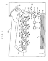
- FIG. 1 an image forming apparatus 1 provided with a sheet feeding device according to an embodiment of the present invention is described.
- the image forming apparatus 1 is an electrophotographic color printer and forms a color image by combining four color (Y: yellow, M: magenta, C: cyan and K: black) images in a tandem method.
- the image forming apparatus 1 is to form an image on a sheet of paper P in accordance with image data, and comprises a printing section 2, a feeding section 15, a sheet feeding device 35, a fixing device 22 and a printed-sheet tray 23.
- the feeding section 15 is to supply sheets P one by one, and comprises a sheet tray 16, a feed-out roller 17 and separation rollers 18. A plurality of sheets to be subjected to printing is stacked in the sheet tray 16.
- the feed-out roller 17 is to pick the sheets P out of the tray 16 one by one.
- the separation rollers 18 separate two or more sheets possibly picked out by the feed-out roller 17 and feed surely one sheet P forward.
- the sheet feeding device 35 comprises feed rollers 19, timing rollers 20, a control unit 30, a driver 31, a storage 32, an overlap correction mechanism 40, a route R and sensors Se1 to Se5.
- the feed rollers 19 are rotated by the driver 31 to feed the sheet P at a speed "Va".
- the driver 31 is, for example, a motor.
- the feed rollers 19 and the driver 31 form a feeder.
- the timing rollers 20 are rotated by another driver (not shown) to feed the sheet P fed thereto by the feed rollers 19 further to a printing section 2 at a speed "Vb".
- the timing rollers 20 and the driver form another feeder.
- the route R is formed between the feed rollers 19 and the timing rollers 20, and the sheet P travels therein.
- the sensors Se1 to Se5 are provided along the route R.
- the sensors Se1 to Se5 detect the gap between the sheets P1 and P2. More specifically, while the sheet P1 is being fed by the timing rollers 20 and while the sheet P2 is being fed by the feed rollers 19, the gap “g" between the trailing edge of the sheet P1 and the leading edge of the sheet P2 (which is hereinafter referred to as the gap "g" between the sheets P1 and P2) is detected by the plural sensors Se1 to Se5 provided along the route R.
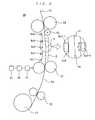
- Each of the sensors Se1 to Se5 comprises a light source Se1-1 (Se2-1, Se3-1, Se4-1 or Se5-1) and a light receiving element Se1-2 (Se2-2, Se3-2, Se4-2 or Se5-2).
- the light source Se3-1 and the light receiving element Se3-2 are shown in the magnified view in Fig. 2 .
- the light sources Se1-1 to Se5-1 emit light.
- the light receiving elements Se1-2 to Se5-2 define detection points.
- the light receiving elements Se1-2 to Se5-2 receive the light emitted from the light sources Se1-1 to Se5-1 and send the control unit 30 output signals Sig1 to Sig 5 in accordance with the quantities of received light.
- the elements Se1-2 to Se5-2 when the light receiving elements Se1-2 to Se5-2 receive relatively large quantities of light, the elements Se1-2 to Se5-2 send output signals Sig1 to Sig5 of relatively high voltages, and when the light receiving elements Se1-2 to Se5-2 receive relatively small quantities of light, the elements Se1-2 to Se5-2 send output signals Sig1 to Sig5 of relatively low voltages.
- the light receiving elements Se1-2 to Se5-2 have a dimension (length) "1" in the sheet feeding direction.
- the sensors Se1 to Se5 are arranged at intervals larger than the initial gap "g" between the sheets P1 and P2, so that the gap "g" will never be detected by two or more sensors concurrently.
- the control unit 30 controls the driver 31 and the feed rollers 19 in accordance with the detection results of the sensors Se1 to Se5.
- the storage 32 is, for example, a hard disk or a memory, and stores a table as shown by Table 1.
- the table shows the relationship between the size "L” of the gap "g” and the speed "Va”.
- Table 1 Size "L” of Gap "g” Speed "Va” 0 V1 0 ⁇ L ⁇ L1 V2 L1 ⁇ L ⁇ L2 V3 L2 ⁇ L ⁇ L3 V4 L3 ⁇ L V5
- the control unit 30 recognizes the size "L” of the gap “g” based on the output signals Sig1 to Sig5 from the sensors Se1 to Se5 and determines the speed "Va” with reference to the table.
- the control unit 30 controls the driver 31 and the feed rollers 19 such that the gap "g" detected by a more downstream sensor of the sensors Se1 to Se5 will be smaller than the gap "g” detected by a more upstream sensor of the sensors Se1 to Se5.
- the control unit 30 controls the driver 31 and the feed rollers 19 such that the speed "Va” will be V1 that is equal to the speed "Vb".
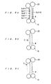
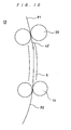
- the overlap correction mechanism 40 is to correct an overlap of the sheets P1 and P2. Specifically, as shown in Figs. 1 and 2 , the overlap correction mechanism 40 is provided in a downstream position in the route R (near the timing rollers 20), and is a roller that has a cross section of a circle having a protrusion. If the sheets P1 and P2 reach the overlap correction mechanism 40 while overlapping with each other, the leading edge of the sheet P2 is hooked by the protrusion of the overlap correction mechanism 40 as shown by Fig. 3a . Then, as shown by Fig. 3b , the sheet P2 is pushed up by the force of the feed rollers 19, and accordingly, the overlap correction mechanism 40 is rotated.
- the overlap correction mechanism 40 rotates by a specified amount, as shown by Fig. 3c , the leading edge of the sheet P2 is released from the protrusion of the overlap correction mechanism 40, and the sheet P2 is fed upward. Thereafter, the overlap correction mechanism 40 rotates further and returns to a state as shown by Fig. 3a . In this way, the sheet P2 slows down. Meanwhile, during the period from Fig. 3a to Fig. 3c , the sheet P1 is fed upward without slowing down. Thereby, the overlap of the sheets P1 and P2 is corrected.
- the printing section 2 is to form a toner image on a sheet P fed from the timing rollers 20.
- the printing section 2 comprises image forming units 24Y, 24M, 24C and 24K, first transfer rollers 8Y, 8M, 8C and 8K, an intermediate transfer belt 11, a driving roller 12, a driven roller 13, a second transfer roller 14, and a cleaning device 21.
- the image forming units 24Y, 24M, 24C and 24K comprise photosensitive drums 4Y, 4M, 4C and 4K, electric chargers 5Y, 5M, 5C and 5K, exposure devices 6Y, 6M, 6C and 6K, developing devices 7Y, 7M, 7C and 7K, and cleaners 9Y, 9M, 9C and 9K, respectively.
- the photosensitive drums, the electric chargers, the exposure devices, the developing devices, the first transfer rollers, the cleaners and the image forming units are discussed generally, they are indicated as the photosensitive drum(s) 4, the electric charger(s) 5, the exposure device(s) 6, the developing device(s) 7, the first transfer roller(s) 8, the cleaner(s) 9 and the image forming unit(s) 24.
- the photosensitive drums, the electric chargers, the exposure devices, the developing devices, the first transfer rollers, the cleaners and the image forming units are discussed individually, they are indicated as the photosensitive drums 4Y, 4M, 4C and 4K, the electric chargers 5Y, 5M, 5C and 5K, the exposure devices 6Y, 6M, 6C and 6K, the developing devices 7Y, 7M, 7C and 7K, the first transfer rollers 8Y, 8M 8C and 8K, the cleaners 9Y, 9M, 9C and 9K, and the image forming units 24Y, 24M, 24C and 24K.
- the electric chargers 5 charge the circumferential surfaces of the photosensitive drums 4.
- the exposure devices 6 emit lasers controlled by an exposure control unit (not shown in the drawings). Thereby, electrostatic latent images are formed on the circumferential surfaces of the photosensitive drums 4.
- the electric chargers 5 and the exposure devices 6 serve as a unit for forming electrostatic latent images on the circumferential surfaces of the photosensitive drums 4.
- the developing devices 7 are to supply toner to the photosensitive drums 4 so as to form toner images on the circumferential surfaces of the photosensitive drums 4. More specifically, the developing devices 7 store toner therein and charge the toner into the negative polarity by stirring the toner or the like. Developing rollers provided in the respective developing device 7 feed the toner toward the photosensitive drums 4. At this time, the negative charged toner moves from the developing rollers to the photosensitive drums 4 influenced by the electric fields of the electrostatic latent images on the photosensitive drums 4. In this way, toner images are formed on the circumferential surfaces of the photosensitive drums 4.
- the intermediate transfer belt 11 is laid between the driving roller 12 and the driven roller 13, and the toner images formed on the photosensitive drums 4 are transferred onto the intermediate transfer belt 1 such that the transferred images will be laid on one another to be combined into a full-color image (first transfer).
- the first transfer rollers 8 are located in contact with the inner surface of the intermediate transfer belt 11.
- a first transfer voltage is applied from a voltage source (not shown in the drawings) to the first transfer rollers 8, whereby the toner images formed on the photosensitive drums 4 are transferred onto the intermediate transfer belt 11.
- the cleaners 9 are to collect residual toner remained on the photosensitive drums 4 after the first transfer.
- the driving roller 12 is rotated by an intermediate transfer belt driver (not shown in the drawings), whereby the intermediate transfer belt 11 is driven. Then, the intermediate transfer belt 11 carries the full-color toner image to the second transfer roller 14.
- the second transfer roller 14 is located opposite the intermediate transfer belt 11, and a nip portion N is formed between the second transfer roller 14 and the intermediate transfer belt 11. While a sheet P fed from the timing rollers 20 is passing through the nip portion N, the second transfer roller 14 transfers the toner image carried by the intermediate transfer belt 11 onto the sheet P (second transfer). After the second transfer, the cleaning device 21 removes residual toner from the intermediate transfer belt 11.
- the sheet P that has been subjected to the second transfer is fed to the fixing device 22.
- the fixing device 22 applies a heating treatment and a pressing treatment to the sheet P so as to fix the toner image on the sheet P.
- the printed sheet P is ejected onto the printed-sheet tray 23.
- the operation of the image forming apparatus 1 is generally described.
- the light receiving elements Se1-2 to Se5-2 receive relatively large quantities of light
- the light receiving elements Se1-2 to Se5-2 output signals Sig1 to Sig5 of relatively high voltages.
- the light receiving elements Se1-2 to Se5-2 receive relatively small quantities of light
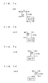
- the light receiving elements Se1-2 to Se5-2 output signals Sig1 to Sig5 of relatively low voltages. Therefore, referring to Fig. 5 , while the output signals Sig1 to Sig5 are high (during the periods between time "0" to time “t3"), the gap "g" between the sheets P1 and P2 are passing in front of the light receiving elements Se1-2 to Se5-2, respectively.
- the size "L” of the gap “g” can be judged from the length of the period when the voltage of the output signal Sig1 to Sig5 is high.
- the control unit 30 times the period and calculates the size "L” of the gap “g” between the sheets P1 and P2, and in accordance with the calculation result, the control unit 30 controls the speed "Va".
- the waveforms of the output signals Sig1 to Sig5 can be classified into three types. More specifically, the waveforms of the output signals Sig1 and Sig2 are trapezoidal. The waveform of the output signal Sig3 is four-cornered with the upper side slanting. The waveform of the output signal Sig4 is triangle. The output signal Sig5 is constant and flat, which indicates that the gap "g" between the sheets P1 and P2 is zero.
- the output signals Sig1 to Sig5 have different waveforms.
- the output signal “Sign” has such a waveform as those of the output signals Sig1 and Sig2.
- Figs. 7a to 7d when the size "L” of the gap “g” is smaller than the size of the light receiving element Sen-2, the output signal “Sign” has such a waveform as that of the output signal Sig3.
- Fig. 8a to 8c when the gap "g" becomes zero while passing in front of the light receiving element Sen-2, the output signal “Sign” has such a waveform as that of the output signal Sig4. This is described in more details below.
- the light receiving element Sen-2 is covered neither by the sheet P1 nor by the sheet P2. Accordingly, the voltage of the output signal “Sign” is fixed at a relatively high level like the output signals Sig1 and Sig2 in the periods from “t1" to "t2" shown in Fig. 5 .
- the area of the light receiving element Sen-2 covered by the sheet P2 is increasing. Accordingly, the voltage of the output signal “Sign” is decreasing like the output signals Sig1 and Sig2 in the periods from “t2" to “t3" shown in Fig. 5 .
- the timings of the passing of the trailing edge of the sheet P1 and the passing of the leading edge of the sheet P2 in front of the light receiving element Sen-2 depend on the size "L" of the gap "g".
- the control unit 30 recognizes the passing of the trailing edge of the sheet P1 and the passing of the leading edge of the sheet P2, based on the waveform of the output signal "Sign" from the light receiving element Sen-2. Referring to Fig. 4 , the operation of the image forming apparatus 1 is hereinafter described, focusing on this point.
- the control unit 30 sets N to 1 at step S1.
- This step S1 is carried out, for example, based on the time when the leading edge of the sheet P1 is detected by the sensor Se5 located the most downstream in the route R.
- the control unit 30 judges whether the sensor "Sen” (n: integer from 1 to 5) detects the trailing edge of the sheet P1 during a period when the trailing edge of the sheet P1 is expected to come thereto (step S2). While the trailing edge of the sheet P1 is passing in front of the light receiving element Sen-2, the covered area of the light receiving element Sen-2 is decreasing, and the quantity of light received by the light receiving element Sen-2 is increasing. Accordingly, the voltage of the output signal "Sign" from the light receiving element Sen-2 is increasing.
- the control unit 30 judges the up-edge of the output signal "Sign" as the time when the sensor "Sen” starts detecting the trailing edge of the sheet P1. Thereafter, the processing goes to step S4. On the other hand, when the trailing edge of the sheet P1 is not detected, the control unit 30 judges that there is no gap between the sheets P1 and P2. Then, the processing goes to step S3.
- the control unit 30 sets the speed "Va” to V1 at step S3. In this procedure, when the control unit 30 judges that there is no gap between the sheets P1 and P2, the control unit 30 judges that adjustment of the speed "Va” is not necessary. Therefore, the control unit 30 sets the speed "Va” to V1 that is equal to the speed "Vb". Thereafter, the processing goes to step S18.
- step S5 when the leading edge of the sheet P2 has reached the light receiving element "Sen-2", the light receiving element "Sen-2" starts to be covered by the sheet P2. Therefore, at this time, also, the quantity of light received by the light receiving element "Sen-2” stops increasing, and accordingly, the increase in the voltage of the output signal "Sign” stops.
- the control unit 30 cannot judge whether the stop of the increase in the voltage of the output signal "Sign” is due to the completion of the passing of the trailing edge of the sheet P1 by the light receiving element "Sen-2” or due to the arrival of the leading edge of the sheet P2 at the light receiving element "Sen-2". This judgment is made at step S7 that will be described later.
- step S6 When the increase in the voltage of the output signal "Sign” stops, the processing goes to step S6. Unless the increase in the voltage of the output signal "Sign” stops, the processing returns to step S5. Until the increase in the voltage of the output signal "Sign” stops, the process at step S5 is repeated.
- step S6 the control unit 30 takes in a value of the time "t1" (see Fig. 5 ) when the increase in the voltage of the output signal "Sign" stops.
- the control unit 30 judges whether the value "t1" is equal to a value "ta” (step S7).
- the value “ta” is obtained by dividing the length "1" of the light receiving element "Sen-2” by the speed "Vb", and therefore, the value “ta” indicates the time that is necessary for the trailing edge of the sheet P1 to complete passing by the light receiving element "Sen-2".
- the speed "Vb" is a fixed value known to the control unit 30.
- step S7 by judging whether the value "t1" is equal to the value "ta", the control unit 30 judges whether the stop of the increase in the voltage of the output signal "Sign" is due to the completion of the passing of the trailing edge of the sheet P1 by the light receiving element "Sen-2" as shown by Fig. 6b or due to the arrival of the leading edge of the sheet P2 at the light receiving element "Sen-2” as shown by Figs. 7b and 8b . In other words, the control unit 30 judges which waveform of the output signals Sig1 to Sig4 shown in Fig. 5 the output signal "Sign" has.
- step S8 When the value "t1" is equal to the value "ta”, the control unit 30 judges that the stop of the increase in the voltage of the output signal “Sign” is due to the completion of the passing of the trailing edge of the sheet P1 by the light receiving element "Sen-2" (see the waveforms of the signals Sig1 and Sig2 in Fig. 5 ). Thereafter, the processing goes to step S8.
- the control unit 30 judges that the stop of the increase in the voltage of the output signal "Sign” is due to the arrival of the leading edge of the sheet P2 at the light receiving element "Sen-2” (see the waveforms of signals Sig3 and Sig4 in Fig. 5 ). Thereafter, the processing goes to step S10.
- the control unit 30 judges at step S8 whether the sensor "Sen” has detected the leading edge of the sheet P2. As shown by Figs. 6c and 6d , while the leading edge of the sheet P2 is passing by the light receiving element "Sen-2", the area of the light receiving element “Sen-2” covered by the sheet P2 is increasing. Accordingly, the quantity of light received by the light receiving element “Sen-2” is decreasing, and the voltage of the output signal “Sign” from the light receiving element “Sen-2” is decreasing like the output signals Sig1 and Sig2 for the periods from “t2" to "t3".
- the control unit 30 judges the down-edge of the output signal "Sign” as the time when the leading edge of the sheet P2 has reached the light receiving element "Sen-2".
- the process at step S8 is repeated until the sensor "Sen” starts detecting the leading edge of the sheet P2. Then, when the control unit 30 judges that the leading edge of the sheet P2 has reached the light receiving element "Sen-2", the processing goes to step S9.
- step S10 the control unit 30 subsequently judges whether the time "t1" is smaller than "ta” (step S10).
- the time “ta” is a time that is necessary for the trailing edge of the sheet P1 to complete passing by the light receiving element "Sen-2". Therefore, in the normal state, the time “t1” is equal to or smaller than "ta", and it never happens that the time "t1" is greater than "ta”. Accordingly, when it is judged that the time "t1" is greater than "ta” ("NO” at step S10), the control unit 30 judges that an error has occurred. Then, the processing is terminated. On the other hand, when the time "t1" is smaller than "ta”, the processing goes to step S11.
- the control unit 30 judges whether the trailing edge of the sheet P1 has completed passing by the light receiving element "Sen-2".
- the light receiving element "Sen-2” is covered by only the sheet P2 as shown by Fig. 7c . Because the sheet P2 travels in such a direction as to cover more part of the light receiving element "Sen-2", the voltage of the output signal "Sign” is steeply decreasing like the output signal Sig3 in the period from “t2" to "t3" shown in Fig. 5 .
- control unit 30 judges whether the trailing edge of the sheet P1 has completed passing by the light receiving element "Sen-2" by judging whether the decreasing speed in the voltage of the output signal "Sign" is accelerated.
- step S11 the processing goes to step S9.
- step S12 the processing goes to step S12.
- the control unit 30 judges whether the voltage of the output signal "Sign" is zero. In other words, at step S12, the control unit 30 judges whether the leading edge of the sheet P2 has caught up with the trailing edge of the sheet P1 while the light receiving element "Sen-2" is detecting the trailing edge of the sheet P1 and the leading edge of the sheet P2 as shown by the output signal Sig4 in Fig. 5 and Figs. 8a-8c .
- the control unit 30 judges that the leading edge of the sheet P2 has caught up with the trailing edge of the sheet P1. Thereafter, the processing goes to step S13.
- the control unit 30 judges that the leading edge of the sheet P2 has not caught up with the trailing edge of the sheet P1. Thereafter, the processing returns to step S11.
- step S13 When the voltage of the output signal "Sign" is zero, the size “L” of the gap “g” between the sheets P1 and P2 is judged to be zero (step S13). Thereafter, the processing goes to step S17.
- the control unit 30 takes in a value of the time "t2" (see Fig. 5 ) when the voltage of the output signal "Sign” starts decreasing due to the detection at step S8 or the detection at step S11. Thereafter, at step S14, the control unit 30 judges whether the leading edge of the sheet P2 has completed passing by the light receiving element "Sen-2". When and after the leading edge of the sheet P2 has completed passing by the light receiving element "Sen-2", the light receiving element "Sen-2" is completely covered by the sheet P2. Accordingly, the quantity of light received by the light receiving element "Sen-2" becomes zero, and the voltage of the output signal "Sign" becomes zero.
- control unit 30 judges whether the leading edge of the sheet P2 has completed passing by the light receiving element "Sen-2” by judging whether the voltage of the output signal "Sign" has become zero.
- the processing goes to step S15. The process at step S14 is repeated until it is judged that the leading edge of the sheet P2 has completed passing by the light receiving element "Sen-2".
- the control unit 30 takes in a value of the time "t3" (see Fig. 5 ) when the leading edge of the sheet P2 has completed passing by the light receiving element "Sen-2".
- step S17 the control unit 30 controls the driver 31 and the feed rollers 19 to adjust the speed "Va” in accordance with the size "L” of the gap "g". More specifically, the control unit 30 specifies a value for the speed "Va”, referring to Table 1, and the control unit 30 controls the driver 31 and the feed rollers 19 so that the sheet P2 will be fed at the specified speed "Va”. Since the speeds V2, V3, V4 and V5 in Table 1 are larger than the speed "Vb", the gap "g" between the sheets P1 and P2 will be decreasing. Then, the processing goes to step S18.
- Step S18 the control unit 30 judges whether N is equal to five.
- Step S18 is a process to judge whether the processes from step S2 to step S 17 have been carried out with regard to all the sensors Se1 to Se5.
- N is equal to five
- the procedure is completed.
- N is not eual to five
- the processing goes to step S19.
- step S19 the control unit 30 resets the timer. Subsequently, the control unit 30 makes an increment of N at step S20. Thereafter, the processing returns to step S2.
- the gap "g" detected by a more downstream sensor of the sensors Se1 to Se5 is smaller than the gap "g" detected by a more upstream sensor.
- the gap "g" between two sheets P1 and P2 that are sequentially fed can be made closer to zero.
- a plurality of sensors Se1 to Se5 are provided in the sheet route R at a plurality of locations, and the control unit 30 can adjust the speed "Va" of the sheet P2 fed by the feed rollers 19 at a plural number of times. Accordingly, the sheet feeding device 35 can control the speed "Va” more precisely, compared with the sheet feeding device disclosed by Reference 1 that detects the gap between sheets only once.
- the sheet feeding device 35 and the image forming apparatus 1 provided with the sheet feeding device 35 consequently, it is possible to make the gap "g" between sheets P1 and P2 closer to zero. Thereby, the lives of the feed rollers 19 and the intermediate transfer belt 11 are prolonged, and the productivity is improved.
- the gap "g" between sheets P1 and P2 can be made closer to zero, and even if the speeds "Va” and “Vb” are low, the productivity can be maintained high. If the speeds "Va” and “Vb” are low, the speed of a sheet traveling in the fixing device 22 is also low, which permits the fixing temperature of the fixing device 22 to be set low. Thereby, the power consumption of the image forming apparatus 1 can be lowered.
- an overlap correction mechanism 40 is provided, and even if the sheets P1 and P2 overlap with each other, the overlap can be corrected by the overlap correction mechanism 40.
- the sheet feeding device 35 and the image forming apparatus 1 provided with the sheet feeding device 35 are not limited to the embodiment above. Modifications are possible within the scope of the invention. In the following, modifications of the sheet feeding device 35 and the image forming apparatus 1 provided with the sheet feeding device 35 is described.
- Figs. 9a-9c show modifications of the sensors Se1 to Se5 for the sheet feeding device 35.
- a light receiving member Se1-2 may be provided for the light sources Se1-1 to Se5-1.
- a camera "C” may be provided instead of the sensors Se1 to Se5.
- the camera "C” is preferably located in a position suited to take pictures mainly around the timing rollers 20 as shown by Fig. 9c . This is because the target is that the gap "g" becomes zero before the gap "g” comes to the timing rollers 20.
- control unit 30 adjusts the speed “Va” while fixing the speed "Vb".
- speed “Vb” may be adjusted, while the speed “Va” may be fixed.
- the control unit 30 controls the timing rollers 20 and a driver for the timing rollers 20 so that the speed "Vb" will be lower than the speed "Va”.
- the control unit 30 may control the feed rollers 19 and the driver 31 or the timing rollers 20 and the driver for the timing roller 20 so that the speed "Va" will be lower than the speed "Vb".
- the control unit 30 makes a control so as to form a gap "g" between the sheets P1 and P2 once and then to close the gap "g". Thereby, the sheets P1 and P2 can be prevented from going out of the route R while overlapping with each other.
- control unit 30 may control the feed rollers 19 and the driver 31 or the timing rollers 20 and the driver for the timing rollers 20 so that the speed "Va" will be lower than the speed "Vb".
- the overlap correction mechanism 40 is not limited to have the structure shown by Fig. 2 .
- Fig. 10 shows a modified overlap correction mechanism 40'.
- the overlap correction mechanism 40' is made by bending a guide plate that is a component of the route R. The leading edge of the sheet P2 is hooked by the guide plate, and thereby, an overlap of the sheets P1 and P2 is corrected.
Landscapes
- Engineering & Computer Science (AREA)
- Mechanical Engineering (AREA)
- Control Or Security For Electrophotography (AREA)
- Paper Feeding For Electrophotography (AREA)
- Controlling Sheets Or Webs (AREA)
- Delivering By Means Of Belts And Rollers (AREA)
- Sheets, Magazines, And Separation Thereof (AREA)
Applications Claiming Priority (1)
| Application Number | Priority Date | Filing Date | Title |
|---|---|---|---|
| JP2008317144A JP4650564B2 (ja) | 2008-12-12 | 2008-12-12 | シート搬送装置及びこれを備えた画像形成装置 |
Publications (2)
| Publication Number | Publication Date |
|---|---|
| EP2196420A2 true EP2196420A2 (de) | 2010-06-16 |
| EP2196420A3 EP2196420A3 (de) | 2011-02-23 |
Family
ID=42026862
Family Applications (1)
| Application Number | Title | Priority Date | Filing Date |
|---|---|---|---|
| EP09015252A Withdrawn EP2196420A3 (de) | 2008-12-12 | 2009-12-09 | Blattzuführvorrichtung und Bilderzeugungsvorrichtung mit der Blattzuführvorrichtung |
Country Status (4)
| Country | Link |
|---|---|
| US (1) | US20100148431A1 (de) |
| EP (1) | EP2196420A3 (de) |
| JP (1) | JP4650564B2 (de) |
| CN (1) | CN101746627B (de) |
Families Citing this family (7)
| Publication number | Priority date | Publication date | Assignee | Title |
|---|---|---|---|---|
| KR101350117B1 (ko) * | 2009-10-20 | 2014-01-09 | 캐논 가부시끼가이샤 | 시트 검지 장치 및 화상 형성 장치 |
| JP6366219B2 (ja) * | 2012-08-07 | 2018-08-01 | キヤノン株式会社 | 画像形成装置 |
| JP5825267B2 (ja) * | 2013-01-21 | 2015-12-02 | コニカミノルタ株式会社 | 画像処理装置およびモーターの回転制御方法 |
| CN104660855A (zh) * | 2013-11-20 | 2015-05-27 | 崴强科技股份有限公司 | 扫描影像校正装置及校正方法 |
| JP6472276B2 (ja) * | 2015-03-05 | 2019-02-20 | キヤノン株式会社 | 画像形成装置 |
| JP6164246B2 (ja) * | 2015-04-27 | 2017-07-19 | コニカミノルタ株式会社 | 画像形成装置 |
| JP2017203875A (ja) * | 2016-05-11 | 2017-11-16 | キヤノン株式会社 | 画像形成装置 |
Citations (1)
| Publication number | Priority date | Publication date | Assignee | Title |
|---|---|---|---|---|
| JP2006232475A (ja) | 2005-02-24 | 2006-09-07 | Konica Minolta Business Technologies Inc | シート給送装置および画像形成装置 |
Family Cites Families (24)
| Publication number | Priority date | Publication date | Assignee | Title |
|---|---|---|---|---|
| US4451027A (en) * | 1980-01-09 | 1984-05-29 | Burroughs Corp. | Constant spacing document feeder |
| US4541624A (en) * | 1982-03-24 | 1985-09-17 | Nippon Electric Co., Ltd. | Flat article feeding apparatus |
| JP3208193B2 (ja) * | 1991-12-09 | 2001-09-10 | 株式会社リコー | 画像形成装置のシート給送方法とそのシート給送方法を実施するシート給送装置 |
| US5749569A (en) * | 1992-10-15 | 1998-05-12 | Minolta Camera Kabushiki Kaisha | Document feeding apparatus having improved forwarding means |
| IT1261545B (it) * | 1993-04-09 | 1996-05-23 | Finmeccanica Spa | Dispositivo singolarizzatore |
| US5423527A (en) * | 1993-11-05 | 1995-06-13 | Unisys Corporation | Document transport with gap adjust |
| US5461468A (en) * | 1994-10-31 | 1995-10-24 | Xerox Corporation | Document handler interdocument gap control system |
| JP2659344B2 (ja) * | 1995-02-10 | 1997-09-30 | 日本電気ロボットエンジニアリング株式会社 | 紙葉類の摩擦式供給機構 |
| DE19607304C1 (de) * | 1996-02-27 | 1997-07-31 | Aeg Electrocom Gmbh | Verfahren zur Steuerung einer Abzugsvorrichtung für flache Sendungen von einem Stapel |
| JP2000335785A (ja) * | 1999-05-25 | 2000-12-05 | Canon Inc | シート搬送装置および画像形成装置 |
| JP2001301998A (ja) * | 2000-02-15 | 2001-10-31 | Canon Inc | シート搬送装置及びこれを備えた画像形成装置並びに画像読取装置 |
| JP2002037474A (ja) * | 2000-07-18 | 2002-02-06 | Canon Inc | シート給送装置及び該装置を備える画像形成装置 |
| US6651980B2 (en) * | 2001-06-13 | 2003-11-25 | Canon Kabushiki Kaisha | Sheet conveying apparatus with correction device to compensate for sheet interval variation |
| US6644660B2 (en) * | 2001-10-26 | 2003-11-11 | Pitney Bowes Inc. | Dynamic pitch correction for an output inserter subsystem |
| US6554275B1 (en) * | 2001-12-04 | 2003-04-29 | Unisys Corporation | Method and system for document overlap/gap error detection and correction |
| US6685184B2 (en) * | 2002-03-11 | 2004-02-03 | Pitney Bowes Inc | Transport method and system for controlling timing of mail pieces being processed by a mailing system |
| JP2003316230A (ja) * | 2002-04-26 | 2003-11-07 | Canon Inc | 画像形成装置 |
| JP4062694B2 (ja) * | 2003-04-23 | 2008-03-19 | 株式会社リコー | シート搬送装置、および画像形成装置 |
| JP2004331357A (ja) * | 2003-05-09 | 2004-11-25 | Ricoh Co Ltd | 用紙搬送装置及びその用紙搬送装置を具備する画像形成装置 |
| JP2005001833A (ja) * | 2003-06-12 | 2005-01-06 | Fuji Photo Film Co Ltd | シート搬送装置 |
| JP4157810B2 (ja) * | 2003-07-25 | 2008-10-01 | 東北リコー株式会社 | 中間搬送部付き大量給紙装置 |
| JP4570941B2 (ja) * | 2004-11-19 | 2010-10-27 | 株式会社リコー | 用紙搬送装置及びこれを使用した画像形成装置 |
| JP4759468B2 (ja) * | 2006-08-07 | 2011-08-31 | キヤノン株式会社 | シート搬送装置及び画像形成装置 |
| DE102008009876A1 (de) * | 2008-02-19 | 2009-08-20 | Siemens Aktiengesellschaft | Vorrichtung zum Transport von flachen Gegenständen |
-
2008
- 2008-12-12 JP JP2008317144A patent/JP4650564B2/ja not_active Expired - Fee Related
-
2009
- 2009-12-09 EP EP09015252A patent/EP2196420A3/de not_active Withdrawn
- 2009-12-10 US US12/635,378 patent/US20100148431A1/en not_active Abandoned
- 2009-12-10 CN CN2009102534375A patent/CN101746627B/zh active Active
Patent Citations (1)
| Publication number | Priority date | Publication date | Assignee | Title |
|---|---|---|---|---|
| JP2006232475A (ja) | 2005-02-24 | 2006-09-07 | Konica Minolta Business Technologies Inc | シート給送装置および画像形成装置 |
Also Published As
| Publication number | Publication date |
|---|---|
| CN101746627B (zh) | 2013-04-17 |
| US20100148431A1 (en) | 2010-06-17 |
| CN101746627A (zh) | 2010-06-23 |
| JP2010137974A (ja) | 2010-06-24 |
| EP2196420A3 (de) | 2011-02-23 |
| JP4650564B2 (ja) | 2011-03-16 |
Similar Documents
| Publication | Publication Date | Title |
|---|---|---|
| US7068969B2 (en) | Method and apparatus for image forming capable of performing fast and stable sheet transfer operations | |
| US7796928B2 (en) | Image forming apparatus | |
| EP2196420A2 (de) | Blattzuführvorrichtung und Bilderzeugungsvorrichtung mit der Blattzuführvorrichtung | |
| US8205883B2 (en) | Paper transport path of image forming apparatus | |
| US9454120B2 (en) | Image forming apparatus | |
| US10162296B2 (en) | Transport monitoring control device and image forming apparatus | |
| US9891557B2 (en) | Image formation apparatus having intermediate transfer belt speed control | |
| US9164455B2 (en) | Image forming apparatus | |
| JP2002108164A (ja) | 画像形成装置および画像形成方法 | |
| JP2001100612A (ja) | 画像形成装置 | |
| KR20170017731A (ko) | 화상 형성 장치 | |
| JP2004149265A (ja) | 画像形成装置 | |
| JP2003241474A (ja) | 多色画像形成装置 | |
| JP2004151382A (ja) | 画像形成装置 | |
| JP2004151383A (ja) | 画像形成装置 | |
| JP6163418B2 (ja) | 画像形成装置 | |
| US8606134B2 (en) | Image forming apparatus | |
| JP3884460B2 (ja) | 画像形成装置 | |
| JP2007010861A (ja) | 画像形成装置および方法 | |
| JP2004151384A (ja) | 画像形成装置 | |
| JP4568180B2 (ja) | 画像記録装置 | |
| JP4818022B2 (ja) | 画像形成装置及びその制御方法 | |
| US8554121B2 (en) | Belt driving unit and image forming apparatus | |
| JP4811455B2 (ja) | 検知装置及びこれを備えた画像形成装置 | |
| US20170261890A1 (en) | Image forming apparatus and method of controlling conveyance |
Legal Events
| Date | Code | Title | Description |
|---|---|---|---|
| PUAI | Public reference made under article 153(3) epc to a published international application that has entered the european phase |
Free format text: ORIGINAL CODE: 0009012 |
|
| AK | Designated contracting states |
Kind code of ref document: A2 Designated state(s): AT BE BG CH CY CZ DE DK EE ES FI FR GB GR HR HU IE IS IT LI LT LU LV MC MK MT NL NO PL PT RO SE SI SK SM TR |
|
| AX | Request for extension of the european patent |
Extension state: AL BA RS |
|
| PUAL | Search report despatched |
Free format text: ORIGINAL CODE: 0009013 |
|
| AK | Designated contracting states |
Kind code of ref document: A3 Designated state(s): AT BE BG CH CY CZ DE DK EE ES FI FR GB GR HR HU IE IS IT LI LT LU LV MC MK MT NL NO PL PT RO SE SI SK SM TR |
|
| AX | Request for extension of the european patent |
Extension state: AL BA RS |
|
| RIC1 | Information provided on ipc code assigned before grant |
Ipc: B65H 29/20 20060101ALI20110120BHEP Ipc: B65H 7/14 20060101ALI20110120BHEP Ipc: B65H 5/06 20060101AFI20100326BHEP |
|
| 17P | Request for examination filed |
Effective date: 20110819 |
|
| STAA | Information on the status of an ep patent application or granted ep patent |
Free format text: STATUS: THE APPLICATION HAS BEEN WITHDRAWN |
|
| 18W | Application withdrawn |
Effective date: 20140715 |