EP2195129B1 - Verfahren und vorrichtung zur herstellung von sicherungsscheiben - Google Patents
Verfahren und vorrichtung zur herstellung von sicherungsscheiben Download PDFInfo
- Publication number
- EP2195129B1 EP2195129B1 EP08833856.1A EP08833856A EP2195129B1 EP 2195129 B1 EP2195129 B1 EP 2195129B1 EP 08833856 A EP08833856 A EP 08833856A EP 2195129 B1 EP2195129 B1 EP 2195129B1
- Authority
- EP
- European Patent Office
- Prior art keywords
- washer
- die portion
- blank
- forming
- pattern
- Prior art date
- Legal status (The legal status is an assumption and is not a legal conclusion. Google has not performed a legal analysis and makes no representation as to the accuracy of the status listed.)
- Active
Links
Images
Classifications
-
- B—PERFORMING OPERATIONS; TRANSPORTING
- B21—MECHANICAL METAL-WORKING WITHOUT ESSENTIALLY REMOVING MATERIAL; PUNCHING METAL
- B21D—WORKING OR PROCESSING OF SHEET METAL OR METAL TUBES, RODS OR PROFILES WITHOUT ESSENTIALLY REMOVING MATERIAL; PUNCHING METAL
- B21D53/00—Making other particular articles
- B21D53/16—Making other particular articles rings, e.g. barrel hoops
- B21D53/20—Making other particular articles rings, e.g. barrel hoops washers, e.g. for sealing
- B21D53/22—Making other particular articles rings, e.g. barrel hoops washers, e.g. for sealing with means for preventing rotation
-
- F—MECHANICAL ENGINEERING; LIGHTING; HEATING; WEAPONS; BLASTING
- F16—ENGINEERING ELEMENTS AND UNITS; GENERAL MEASURES FOR PRODUCING AND MAINTAINING EFFECTIVE FUNCTIONING OF MACHINES OR INSTALLATIONS; THERMAL INSULATION IN GENERAL
- F16B—DEVICES FOR FASTENING OR SECURING CONSTRUCTIONAL ELEMENTS OR MACHINE PARTS TOGETHER, e.g. NAILS, BOLTS, CIRCLIPS, CLAMPS, CLIPS OR WEDGES; JOINTS OR JOINTING
- F16B39/00—Locking of screws, bolts or nuts
- F16B39/22—Locking of screws, bolts or nuts in which the locking takes place during screwing down or tightening
- F16B39/24—Locking of screws, bolts or nuts in which the locking takes place during screwing down or tightening by means of washers, spring washers, or resilient plates that lock against the object
-
- F—MECHANICAL ENGINEERING; LIGHTING; HEATING; WEAPONS; BLASTING
- F16—ENGINEERING ELEMENTS AND UNITS; GENERAL MEASURES FOR PRODUCING AND MAINTAINING EFFECTIVE FUNCTIONING OF MACHINES OR INSTALLATIONS; THERMAL INSULATION IN GENERAL
- F16B—DEVICES FOR FASTENING OR SECURING CONSTRUCTIONAL ELEMENTS OR MACHINE PARTS TOGETHER, e.g. NAILS, BOLTS, CIRCLIPS, CLAMPS, CLIPS OR WEDGES; JOINTS OR JOINTING
- F16B43/00—Washers or equivalent devices; Other devices for supporting bolt-heads or nuts
Definitions
- the present invention relates to a method for the manufacturing of washers for locking according to the introductory part of the attached claim 1.
- the present invention also relates to a device for the manufacturing of washers for locking according to the introductory part of the attached claim 10.
- Washers as described above are previously known and provided for eg bolts or the corresponding fastening elements for locking purposes.
- two washers are arranged in a pair, substantially as shown in Fig. 1 , the cam pattern sides facing and engaging each other, the main cam surface inclination being larger than the pitch of the threads, which causes a positive and efficient locking of the fastening element.
- the washers are manufactured from a strip blank, which is fed to pass several stations, in which forming and/or punching is performed between upper and lower tools, the pattern of teeth being formed on and substantially covering the upper surface and the pattern of cams being formed on and substantially covering the lower surface of the washer.
- the object of present invention is to provide a solution to these problems associated with previously known technique.
- the object of the present invention is obtained by a method, and a device having the features specified in claims 1 and 10, respectively.
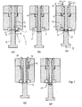
- a die assembly for the manufacturing of locking washers is designated by 1.
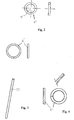
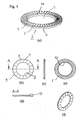
- a washer 2 to be produced according to the invention is shown.
- These kind of locking washer comprises a central hole 3 for a bolt element to be locked by a washer arrangement and on one side 4 a pattern of radially extending teeth 5 and on the other, the opposite, side 6 a pattern of radially extending cams 7.
- the washer has an annular configuration and the respective patterns extend from the inner periphery 8 to the outer periphery 9.
- the washer comprises a bevelled portion 10 at the inner periphery, preferably on the side 4 having the pattern of teeth, the bevelled portion being intended to adapt to a radius portion under the head of a bolt element.
- the die assembly preferably has an axi-symmetric configuration coinciding with the axial direction 11 of a washer to be formed.
- the die assembly comprises a lower die portion 12, an upper portion 13 and a central portion 14. According to the embodiment shown the central die portion is fixed and the lower die portion and the upper die portion are mutually movable and arranged to form a closed shaping space 15 together with the central die portion and a support piece 1' for providing a circumferentially running outer wall of said space, a washer blank 2', being intended to be formed to a washer in said closed shaping space 15.
- the die assembly is open to receive a washer blank 2'.
- the lower die portion having received said blank is movable towards the upper die portion, means, represented by an arrow F, being provided for forcing the lower die portion towards the upper die portion for forming said closed shaping space by the die portions by forcing the upper die portion against an end stop 16 with the washer blank material applied in said space 15, the lower die portion being arranged to be further forced towards the upper die portion for forming the washer blank to a washer as shown in Fig. 1(c) and (d) .
- spring means 17 are provided to provide a spring force F', against which the upper die portion is displaced when forced towards the end stop, said spring force being provided for pushing out the formed washer when unloading the force F exerted by the lower die portion by retracting the lower die portion.
- the spring force is acting on the upper die portion by eg rods 18 acting on an upper portion 19 of the upper die portion, as schematically shown in Fig. 1(d) .
- rods 18 may be imagined and for exerting a spring force F'.
- the die assembly is configured to form the tooth pattern and the cam pattern to extend from the inner periphery 8 of the washer to the outer periphery 9 of the washer.
- the lower die portion 12 is designed to form the pattern of cams and the upper die portion 13 is designed to form the pattern of teeth.
- the die assembly preferably by a bevelled end portion 20 of the central die portion as shown in Fig. 1(e) , is designed to form the washer with a bevelled configuration at the inner periphery to adapt to a radius under the head of a bolt intended to be locked by a washer arrangement, as described earlier, the bevelled configuration preferably being formed on the tooth pattern side 4 of the washer.
- the blank 2' to be formed is cut from a metal strip 2". Such a blank is schematically shown in Fig. 1(b) .
- the blank 2' to be formed in the die assembly is formed from a wire 21 having a circular cross-section, as shown in Fig. 3 .
- the blank 2' to be formed in the die assembly is formed from a wire 21' having a square cross-section, as shown in Fig. 4 .
- annular blank 2' as schematically shown in Fig. 1(b)-(c) , the die assembly is configured for cutting the blank from a strip 2" in the die assembly prior to forming the blank.
- the lower die portion is provided with a circumferentially running edge portion 22 and the die assembly is provided with a support piece 1', which, apart from providing the circumferentially running wall of the closed shaping space, provides a cutting edge 24 for the blank cutting operation, the lower die portion working as a punch in this operation, the operation being schematically shown in Fig. 1(c) .
- Embodiments may also be imagined according to which a blank in the form of a circular disc, ie without a central hole, is produced, the hole being punched out in the die assembly during forming of the washer, preferably by a central die portion.
- the blank may be punched from a strip or being out, preferably by high velocity cutting, from a wire or a bar or a rod, high velocity cutting being performed with a very small play between the cutting dies and, thus produces a blank with a very accurate disc shape.
- a closed shaping space is formed by a lower die, an upper die, a central die and a support piece. Once the blank is properly introduced the total forming operation for the finished washer is performed in said closed space, which offers a number of advantages, including a proper forming of the two patterns with an extension from the inner periphery to the outer periphery.
- one blank or several blanks at the same time is/are formed in one single operation in a closed shaping space,
- die setting is considerably simplified compared to a process in which a final product is formed in consentive forming operations linked together by a blank strip, wherein the forming steps depend on each other and require an extremely accurate mutual setting, which requires continuous monitoring and maintenance.
- annular washer blanks are punched out/cut out from strips or sheets before being introduced into the die assembly 1.
- the blanks may be punched out in a closely packed pattern, which saves the amount of blank raw material.
- These blanks may be fed to the die assembly in any convenient way prior to forming.
- the washers are preferably made of steel, in particular low-alloy steel hardenable to a hardness of about or exceeding 465 HV.
- the washers are designed with an outer diameter for the washer to fit in a standard dimension counter bored hole having a flat bottom, the thickness of the washers being down to less than 1 mm, and according to preferred embodiments the die assembly is designed for forming such washers.
Landscapes
- Engineering & Computer Science (AREA)
- General Engineering & Computer Science (AREA)
- Mechanical Engineering (AREA)
- Forging (AREA)
- Bolts, Nuts, And Washers (AREA)
- Gasket Seals (AREA)
- Mounting, Exchange, And Manufacturing Of Dies (AREA)
Claims (19)
- Verfahren zur Herstellung von kreisförmigen Sicherungsunterlegscheiben aus Rohlingen, wobei eine Unterlegscheibe (2) ein mittiges Loch (3), eine erste ein Muster von sich radial erstreckenden Zähnen (5) umfassende Seite (4) und eine zweite ein Muster von sich radial erstreckenden Nocken (7) umfassende Seite (6) aufweist, gekennzeichnet durch die Schritte zum- Herstellen eines Unterlegscheibenrohlings (2') mit einer ringförmigen Form, umfassend ein mittiges Loch (3);- Einführen des Unterlegscheibenrohlings (2') in eine Ausformeinheit (1) zur Bildung eines geschlossenen Formungsraums (15) durch einen unteren Ausformteil (12), einen entgegengesetzten oberen Ausformteil (13), einen mittigen Ausformteil (14), der sich durch das mittige Loch (3) des Unterlegscheibenrohlings während der Formung erstreckt, und ein Unterstützungsstück (1') zur Bereitstellung einer umlaufenden äußeren Wand des geschlossenen Formungsraums (15),- Formen des Rohlings, in einem einzigen Arbeitsgang, zu einer Unterlegscheibe durch gegenseitige Belegung des unteren (12) und oberen (13) Ausformteils;- Öffnen des geschlossenen Formungsraums (15), um die geformte Unterlegscheibe (2) zu entnehmen.
- Verfahren nach Anspruch 1, gekennzeichnet durch den Schritt zum- Schneiden des Rohlings von einem dünnen Streifen (2").
- Verfahren nach Anspruch 1, gekennzeichnet durch den Schritt zum- Formen des Rohlings von einem Draht (21) mit einem kreisförmigen Querschnitt.
- Verfahren nach Anspruch 1, gekennzeichnet durch den Schritt zum- Formen des Rohlings von einem Draht (21') mit einem viereckigen Querschnitt.
- Verfahren nach einem der vorgehenden Ansprüche, gekennzeichnet durch die Schritte zum- Einführen des Materials des Unterlegscheibenrohlings zwischen dem unteren Ausformteil (12) und dem oberen Ausformteil (13);- Drücken des unteren Ausformteil (12) gegen den oberen Ausformteil (13) zur Bildung des geschlossenen Formungsraums (15) durch die drei Ausformteile und das Unterstützungsstück durch Drücken des oberen Ausformteils (13) gegen einen Endanschlag (16), wobei das Rohlingsmaterial im Raum angebracht ist; und- Formen des Rohlings zu einer Unterlegscheibe durch weiteres Drücken des unteren Ausformteils (12) in Richtung des oberen Ausformteils (13).
- Verfahren nach Anspruch 5, gekennzeichnet durch die Schritte zum- Drücken des oberen Ausformteils (13) in Richtung des Endanschlags gegen eine Federkraft (F'); und- Auspressen der geformten Unterlegscheibe durch den oberen Ausformteil (13) mithilfe der Federkraft beim Entlasten der durch den unteren Ausformteil (12) ausgeübten Kraft (F) durch Zurückziehen des unteren Ausformteils (12).
- Verfahren nach einem der vorgehenden Ansprüche, gekennzeichnet durch die Schritte zum- Formen der Unterlegscheibe mit dem Zahn (5)-Muster und dem Nocken (7)-Muster, sich vom inneren Umfang (8) der Unterlegscheibe zum äußeren Umfang (9) der Unterlegscheibe erstreckend.
- Verfahren nach einem der vorgehenden Ansprüche, gekennzeichnet durch den Schritt zum- Formen der Unterlegscheibe mit einer abgeschrägten Gestaltung (10) am inneren Umfang, damit sie zu einem Radius unter dem Kopf eines Bolzen, der durch eine Unterlegscheibengestaltung gesichert werden soll, passt, wobei die abgeschrägte Gestaltung (10) vorzugsweise auf der Zahnmusterseite (4) der Unterlegscheibe geformt ist.
- Verfahren nach einem der vorgehenden Ansprüche, gekennzeichnet durch den Schritt zum Formen von Unterlegscheiben mit einer Dicke von bis zu weniger als 1 mm, wobei die Unterlegscheiben vorzugsweise einen standardisierten Außendurchmesser aufweisen.
- Vorrichtung zur Herstellung von kreisförmigen Sicherungsunterlegscheiben aus Rohlingen, wobei Unterlegscheiben ein mittiges Loch (3) für ein Bolzenelement, eine erste ein Muster von sich radial erstreckenden Zähnen (5) umfassende Seite (4) und eine entgegengesetzte zweite ein Muster von sich radial erstreckenden Nocken (7) umfassende Seite (6) aufweist; dadurch gekennzeichnet, dass- der zu formende Unterlegscheibenrohling (2') eine ringförmige Form mit einem mittigen Loch (3) aufweist;- eine Ausformeinheit (1') zum Formen des Rohlings bereitgestellt ist, wobei die Ausformeinheit einen unteren Ausformteil (12), einen entgegengesetzten oberen Ausformteil (13), einen mittigen Ausformteil (14) und ein Unterstützungsstück (1') zur Bereitstellung einer umlaufenden äußeren Wand des geschlossenen Formungsraums (15) umfasst;- der untere (12) und obere (13) Ausformteil gegenseitig beweglich sind und eingerichtet sind, um einen geschlossenen Formungsraum (15) zusammen mit dem mittigen Ausformteil und dem Unterstützungsstück (1'), welches eine umlaufende äußere Wand des geschlossenen Formungsraums (15) bereitstellt, zu bilden;- die Ausformeinheit dazu eingerichtet ist, einen Unterlegscheibenrohling (2') entgegenzunehmen und eine Unterlegscheibe (2), in einem einzigen Arbeitsgang, im geschlossenen Formungsraum (15) zu formen, wobei der mittige Ausformteil dazu eingerichtet ist, sich durch das mittige Loch (3) der Unterlegscheibe während der Formung zu erstrecken.
- Vorrichtung nach Anspruch 10, dadurch gekennzeichnet, dass der in der Ausformeinheit zu formende Rohling von einem dünnen Streifen (2") geschnitten ist.
- Vorrichtung nach Anspruch 10, dadurch gekennzeichnet, dass der in der Ausformeinheit zu formende Rohling von einem Draht (21) mit einem kreisförmigen Querschnitt geformt ist.
- Vorrichtung nach Anspruch 10, dadurch gekennzeichnet, dass der in der Ausformeinheit zu formende Rohling von einem Draht (21') mit einem viereckigen Querschnitt geformt ist.
- Vorrichtung nach einem der Ansprüche 10-13, dadurch gekennzeichnet, dass Mittel (F) zum Drücken des unteren Ausformteils (12) in Richtung des oberen Ausformteils (13) zur Bildung des geschlossenen Formungsraums (15) durch die drei Ausformteile und das Unterstützungsstück durch Drücken des oberen Ausformteils (13) gegen einen Endanschlag (16), wobei das Rohlingsmaterial im Raum angebracht ist, vorgesehen sind, wobei der untere Ausformteil (12) dazu eingerichtet ist, weiter in Richtung des oberen Ausformteils (13) zur Formung des Unterlegscheibenrohlings zu einer Unterlegscheibe gedrückt zu werden.
- Vorrichtung nach Anspruch 14, dadurch gekennzeichnet, dass Federmittel (17) zur Bereitstellung einer Federkraft (F'), gegen welche der obere Ausformteil (13) beim Drücken in Richtung des Endanschlags verschoben wird, vorgesehen sind.
- Vorrichtung nach Anspruch 15, dadurch gekennzeichnet, dass die Federkraft (F') zum Auspressen der geformten Unterlegscheibe durch den oberen Ausformteil (13) beim Entlasten der durch den unteren Ausformteil (12) ausgeübten Kraft (F) durch Zurückziehen des unteren Ausformteils (12) vorgesehen ist.
- Vorrichtung nach einem der Ansprüche 10-16, dadurch gekennzeichnet, dass die Ausformeinheit dazu ausgeformt ist, das Zahn (5)-Muster und das Nocken (7)-Muster sich vom inneren Umfang (8) der Unterlegscheibe zum äußeren Umfang (9) der Unterlegscheibe erstreckend zu formen.
- Vorrichtung nach einem der Ansprüche 10-17, dadurch gekennzeichnet, dass die Ausformeinheit, vorzugsweise der mittige Ausformteil, dazu ausgeformt ist, die Unterlegscheibe mit einer abgeschrägten Gestaltung (10) am inneren Umfang zu formen, damit sie zu einem Radius unter dem Kopf eines Bolzen, der durch eine Unterlegscheibengestaltung gesichert werden soll, passt, wobei die abgeschrägte Gestaltung vorzugsweise auf der Zahnmusterseite (4) der Unterlegscheibe geformt ist.
- Vorrichtung nach einem der Ansprüche 10-18, dadurch gekennzeichnet, dass die Ausformeinheit dazu eingerichtet ist, Unterlegscheiben mit einer Dicke von bis zu weniger als 1 mm und vorzugsweise einem standardisierten Außendurchmesser zu formen.
Priority Applications (2)
| Application Number | Priority Date | Filing Date | Title |
|---|---|---|---|
| EP14171026.9A EP2801419A1 (de) | 2007-09-28 | 2008-09-26 | Sicherungsscheibe |
| PL08833856T PL2195129T3 (pl) | 2007-09-28 | 2008-09-26 | Sposób i urządzenie do wytwarzania podkładek zabezpieczających |
Applications Claiming Priority (2)
| Application Number | Priority Date | Filing Date | Title |
|---|---|---|---|
| SE0702188A SE532183C2 (sv) | 2007-09-28 | 2007-09-28 | Metod och anordning för tillverkning av brickor för låsning |
| PCT/SE2008/051081 WO2009041906A1 (en) | 2007-09-28 | 2008-09-26 | A method and a device for the manufacturing of washers for locking and washer for locking |
Related Child Applications (1)
| Application Number | Title | Priority Date | Filing Date |
|---|---|---|---|
| EP14171026.9A Division EP2801419A1 (de) | 2007-09-28 | 2008-09-26 | Sicherungsscheibe |
Publications (3)
| Publication Number | Publication Date |
|---|---|
| EP2195129A1 EP2195129A1 (de) | 2010-06-16 |
| EP2195129A4 EP2195129A4 (de) | 2011-06-29 |
| EP2195129B1 true EP2195129B1 (de) | 2014-06-04 |
Family
ID=40511695
Family Applications (2)
| Application Number | Title | Priority Date | Filing Date |
|---|---|---|---|
| EP08833856.1A Active EP2195129B1 (de) | 2007-09-28 | 2008-09-26 | Verfahren und vorrichtung zur herstellung von sicherungsscheiben |
| EP14171026.9A Withdrawn EP2801419A1 (de) | 2007-09-28 | 2008-09-26 | Sicherungsscheibe |
Family Applications After (1)
| Application Number | Title | Priority Date | Filing Date |
|---|---|---|---|
| EP14171026.9A Withdrawn EP2801419A1 (de) | 2007-09-28 | 2008-09-26 | Sicherungsscheibe |
Country Status (9)
| Country | Link |
|---|---|
| US (3) | US9636738B2 (de) |
| EP (2) | EP2195129B1 (de) |
| JP (1) | JP5475668B2 (de) |
| KR (1) | KR101669182B1 (de) |
| CN (1) | CN101808761B (de) |
| PL (1) | PL2195129T3 (de) |
| SE (1) | SE532183C2 (de) |
| TW (1) | TWI438349B (de) |
| WO (1) | WO2009041906A1 (de) |
Families Citing this family (18)
| Publication number | Priority date | Publication date | Assignee | Title |
|---|---|---|---|---|
| AT414346B (de) * | 2003-09-05 | 2013-10-15 | Best On Bolt Gmbh | Sicherungselement zur sicherung von schraubenelementen |
| CN102974689B (zh) * | 2012-07-23 | 2015-07-29 | 贵州航天精工制造有限公司 | 外锯齿锁紧垫圈的加工工艺及工装 |
| US9631667B2 (en) * | 2013-03-15 | 2017-04-25 | Rodenhouse, Inc. | Washer and combination washer and fastener system for building construction |
| SE540899C2 (en) | 2015-02-04 | 2018-12-18 | Nord Lock Ab | Wedge locking washer with increased corrosion resistance and method for its manufacture |
| KR101682294B1 (ko) * | 2015-04-08 | 2016-12-02 | 대구가톨릭대학교산학협력단 | 마그네슘합금재 안경테용 프론트프레임의 제조장치 |
| CN107708933A (zh) * | 2016-03-02 | 2018-02-16 | 凯特克分部尤尼克斯公司 | 具有摩擦系数增大处理结构的螺纹紧固件 |
| CN107470430B (zh) * | 2017-08-18 | 2018-11-16 | 重庆友擘机械制造有限公司 | 内齿锁紧垫圈冲压装置 |
| CN107413912B (zh) * | 2017-08-18 | 2018-10-26 | 重庆友擘机械制造有限公司 | 一种用于内齿锁紧垫圈冲压的方法 |
| CN107413972B (zh) * | 2017-08-18 | 2018-12-07 | 重庆友擘机械制造有限公司 | 用于内齿锁紧垫圈的传送加工装置 |
| KR101978424B1 (ko) | 2018-05-21 | 2019-05-14 | 주식회사 에이티에스 | 와셔 조립체 및 와셔 조립체의 조립 방법 |
| KR102078599B1 (ko) * | 2018-10-04 | 2020-02-19 | 백홍기 | 와셔 제조장치 |
| US11242884B2 (en) | 2019-09-18 | 2022-02-08 | Laitram, L.L.C. | Sealing wedge-lock washer and fastening system |
| CN110500434B (zh) * | 2019-09-25 | 2024-05-28 | 江西鸥迪铜业有限公司 | 一种用于电子膨胀阀的阀芯 |
| US11322619B2 (en) | 2019-10-30 | 2022-05-03 | Taiwan Semiconductor Manufacturing Co., Ltd. | Semiconductor device structure and method for forming the same |
| ES2944690T3 (es) * | 2020-03-26 | 2023-06-23 | Teckentrup Gmbh & Co Kg | Arandela de seguridad resistente a la corrosión |
| CN113020398B (zh) * | 2021-03-17 | 2023-06-23 | 重庆科杰实业有限责任公司 | 一种新能源汽车用垫片自动加工设备 |
| TWI810004B (zh) * | 2021-12-08 | 2023-07-21 | 林冠泓 | 華司製造方法 |
| US12385514B1 (en) | 2024-02-09 | 2025-08-12 | Heico Befestigungstechnik Gmbh | Wedge lock washer pair and tensioning arrangement with such wedge lock washer pair |
Family Cites Families (60)
| Publication number | Priority date | Publication date | Assignee | Title |
|---|---|---|---|---|
| US618436A (en) * | 1899-01-31 | Nut-lock | ||
| US1381462A (en) * | 1921-06-14 | Apparatus for mainjfactljriha washers | ||
| US414109A (en) * | 1889-10-29 | Steam-hammer for forging steel wheels | ||
| US653084A (en) * | 1900-03-07 | 1900-07-03 | Hubert C Hart | Method of making washers. |
| US795794A (en) * | 1904-11-26 | 1905-07-25 | Capitol Lock Nut And Washer Company | Means for forming nut-locking washers. |
| US1162566A (en) * | 1911-01-17 | 1915-11-30 | Charles E Bushyeager | Nut-locking washer. |
| US1560135A (en) * | 1919-03-07 | 1925-11-03 | Edgewater Steel | Forging die |
| FR686296A (fr) * | 1929-12-09 | 1930-07-24 | Vis indesserrable | |
| US1915612A (en) | 1931-03-23 | 1933-06-27 | Shakeproof Lock Washer Co | Means for and method of making lock washers |
| US1995357A (en) * | 1933-07-27 | 1935-03-26 | Western Electric Co | Apparatus for forming articles |
| US2193661A (en) * | 1937-08-12 | 1940-03-12 | Leonard A Young | Washer and method of making |
| GB519459A (en) * | 1938-10-04 | 1940-03-27 | Guest Keen & Nettlefolds Ltd | Improvements in locking washers for use with nuts or other screw threaded members |
| US2350756A (en) * | 1939-04-22 | 1944-06-06 | Heinold Gustav Willy | Lock washer |
| US2636253A (en) * | 1948-02-20 | 1953-04-28 | Illinois Tool Works | Means for and method of producing sheet metal lock washers |
| US2665729A (en) * | 1950-06-15 | 1954-01-12 | Chrysler Corp | Split lock washer having movement limiting means |
| US2747266A (en) * | 1952-07-18 | 1956-05-29 | Schostal Soc | Method of cold working blocks bertween dies |
| US2783810A (en) * | 1955-01-03 | 1957-03-05 | Robert A Wrigley | Nut with wedging lock washer and resilient backing washer assembly |
| US2909832A (en) * | 1955-05-31 | 1959-10-27 | Walter F Cousino | Method of making a laminated bearing |
| US3902209A (en) * | 1967-11-13 | 1975-09-02 | Electrical Fittings Corp | Threaded lock washer and method for fabrication thereof |
| US3417802A (en) * | 1967-11-16 | 1968-12-24 | Carl O. Oldenkott | Captive lock washer assembly |
| US3895663A (en) * | 1973-03-15 | 1975-07-22 | Hunsche Donald R | Locking device for threaded fasteners |
| DE2610401C3 (de) * | 1976-03-12 | 1981-10-29 | Adolf Schnorr GmbH & Co KG Spezialfabrik für Tellerfedern, 7032 Sindelfingen | Schraubensicherung |
| JPS52145271U (de) * | 1976-04-27 | 1977-11-04 | ||
| US4274276A (en) | 1978-07-31 | 1981-06-23 | Etablissement Supervis | Method and apparatus for producing a workpiece by extrusion molding |
| DE2927135B1 (de) | 1979-07-05 | 1980-09-11 | Kabel Metallwerke Ghh | Verfahren und Vorrichtung zum Herstellen von Kegelzahnraedern |
| DD148016B1 (de) | 1979-12-19 | 1984-11-14 | Walzlager Und Normteile Veb | Praegewerkzeug fuer unterlegscheiben mit kennzeichnung |
| US4538313A (en) * | 1980-02-15 | 1985-09-03 | Nobex Ab | Method of forming a joined pair of wedge-action lock washers |
| JPS59229298A (ja) | 1983-05-25 | 1984-12-22 | Komatsu Ltd | プレス機械の金型装置 |
| JPS6091339A (ja) | 1983-10-25 | 1985-05-22 | Canon Inc | カメラのバツテリ−チエツク装置 |
| USRE33827E (en) * | 1985-12-19 | 1992-02-18 | Locking fastener | |
| JPS63220941A (ja) | 1987-03-11 | 1988-09-14 | Aida Eng Ltd | 金型構造 |
| US4793752A (en) * | 1987-05-11 | 1988-12-27 | Perma-Tite Ab | Drive-head lock washer |
| US5090855A (en) * | 1990-03-19 | 1992-02-25 | Terry Sydney L | Locking fastener assembly |
| US5190423A (en) * | 1991-02-15 | 1993-03-02 | Ewing Paul E | Locking fastener |
| US5203656A (en) * | 1991-09-19 | 1993-04-20 | Hong Kong Disc Lock Company, Limited | Self-centering, self-tightening fastener |
| US5259819A (en) * | 1991-10-07 | 1993-11-09 | Lee Wen Yuan | Method of manufacturing a washer |
| JP2750390B2 (ja) | 1992-06-01 | 1998-05-13 | 武田工業株式会社 | 座金の製造方法 |
| JP2546107B2 (ja) | 1992-09-30 | 1996-10-23 | ニチデン機械株式会社 | ワッシャ加工供給方法及び装置 |
| US5409338A (en) * | 1993-05-04 | 1995-04-25 | Hong Kong Disc Lock Company, Limited | Wedge-action lock washer assembly having coupled washers |
| DE4412224A1 (de) | 1994-04-09 | 1995-10-12 | Graebener Pressensysteme Gmbh | Presse für eine Kaltverformung von Metallwerkstücken |
| US5626449A (en) * | 1995-09-15 | 1997-05-06 | Hong Kong Disc Lock Company Limited | Wedge-locking fastener assembly with a cammed flange |
| US5746558A (en) * | 1996-07-24 | 1998-05-05 | Lockheed Martin Corporation | Locking apparatus for fastening system |
| JP3565395B2 (ja) | 1997-02-14 | 2004-09-15 | 大豊工業株式会社 | ワッシャの製造方法 |
| WO2000005008A1 (en) | 1998-07-24 | 2000-02-03 | Toto Ltd. | Die forging method |
| US7128511B2 (en) * | 1998-10-30 | 2006-10-31 | John Hewgill | Fastener |
| US6260400B1 (en) * | 1998-12-14 | 2001-07-17 | Gohysu Corporation | Full enclosed forging apparatus |
| JP3085473U (ja) * | 2001-10-19 | 2002-05-10 | 関田金属工業株式会社 | 金属ワッシャ |
| CN1453097A (zh) * | 2002-04-27 | 2003-11-05 | 辉帝企业股份有限公司 | 垫片的制造方法 |
| CN2559823Y (zh) * | 2002-07-31 | 2003-07-09 | 朴明基 | 防松动自锁垫圈 |
| US6776565B2 (en) * | 2002-09-10 | 2004-08-17 | Flamante Industry Ltd. | Structure of an anti-burglar screw bolt |
| US7168902B2 (en) * | 2002-10-09 | 2007-01-30 | Terry Sydney L | Wedge cam lock washer for threaded fasteners |
| US6817278B2 (en) * | 2002-10-22 | 2004-11-16 | Cnh America Llc | Piston assembly for hydraulic cylinder |
| AT414346B (de) * | 2003-09-05 | 2013-10-15 | Best On Bolt Gmbh | Sicherungselement zur sicherung von schraubenelementen |
| CN100345655C (zh) | 2004-03-25 | 2007-10-31 | 金文坤 | 薄板等离子弧焊用的紫铜垫环的制造方法 |
| SE531415C2 (sv) * | 2005-05-31 | 2009-03-31 | Nord Lock Ab | Metod och anordning för tillverkning av brickor och bricka för ett låssystem |
| US7191633B1 (en) * | 2005-11-22 | 2007-03-20 | Honda Motor Co., Ltd. | Forging apparatus |
| JP2007245229A (ja) | 2006-03-20 | 2007-09-27 | Fuji Heavy Ind Ltd | 閉塞鍛造装置 |
| TW200630172A (en) * | 2006-05-18 | 2006-09-01 | Tech Stell Co Ltd | Method for making hexagonal anti-theft and anti-looseness washers |
| US7331874B2 (en) | 2006-07-05 | 2008-02-19 | Tech Stell Co., Ltd. | Method for producing circular washer |
| ES2898940T3 (es) * | 2019-03-13 | 2022-03-09 | Growermetal S R L | Arandela de seguridad para un mejor control de la tensión de los pernos y un alto efecto anti-aflojamiento |
-
2007
- 2007-09-28 SE SE0702188A patent/SE532183C2/sv unknown
-
2008
- 2008-09-26 PL PL08833856T patent/PL2195129T3/pl unknown
- 2008-09-26 WO PCT/SE2008/051081 patent/WO2009041906A1/en not_active Ceased
- 2008-09-26 EP EP08833856.1A patent/EP2195129B1/de active Active
- 2008-09-26 EP EP14171026.9A patent/EP2801419A1/de not_active Withdrawn
- 2008-09-26 CN CN200880108846.XA patent/CN101808761B/zh active Active
- 2008-09-26 US US12/680,000 patent/US9636738B2/en active Active
- 2008-09-26 KR KR1020107006611A patent/KR101669182B1/ko active Active
- 2008-09-26 JP JP2010526851A patent/JP5475668B2/ja active Active
- 2008-09-30 TW TW097137443A patent/TWI438349B/zh active
-
2017
- 2017-03-24 US US15/468,597 patent/US20170259323A1/en not_active Abandoned
-
2021
- 2021-11-29 US US17/536,912 patent/US20220226879A1/en active Pending
Also Published As
| Publication number | Publication date |
|---|---|
| US20220226879A1 (en) | 2022-07-21 |
| SE0702188L (sv) | 2009-03-29 |
| JP2010540253A (ja) | 2010-12-24 |
| EP2801419A1 (de) | 2014-11-12 |
| KR20100061508A (ko) | 2010-06-07 |
| SE532183C2 (sv) | 2009-11-10 |
| JP5475668B2 (ja) | 2014-04-16 |
| CN101808761A (zh) | 2010-08-18 |
| EP2195129A4 (de) | 2011-06-29 |
| US20170259323A1 (en) | 2017-09-14 |
| EP2195129A1 (de) | 2010-06-16 |
| TWI438349B (zh) | 2014-05-21 |
| US20100209214A1 (en) | 2010-08-19 |
| TW200925447A (en) | 2009-06-16 |
| WO2009041906A1 (en) | 2009-04-02 |
| PL2195129T3 (pl) | 2014-11-28 |
| US9636738B2 (en) | 2017-05-02 |
| KR101669182B1 (ko) | 2016-10-25 |
| CN101808761B (zh) | 2016-06-08 |
Similar Documents
| Publication | Publication Date | Title |
|---|---|---|
| EP2195129B1 (de) | Verfahren und vorrichtung zur herstellung von sicherungsscheiben | |
| DE102008006065B4 (de) | Verfahren zur Herstellung einer Tellerfeder | |
| EP2662160A1 (de) | Stanzmatrize einer stanzpresse, matrize zum vertiefen von schneiden und verfahren zur herstellung von langen löchern in einer platte | |
| KR20080015879A (ko) | 중공체 요소를 생산하기 위한 방법, 중공체 요소, 부품,중공체 요소를 생산하기 위한 연속식 복합 툴 | |
| DE112011100571T5 (de) | Verfahren zum Herstellen einer Radfelge für ein Fahrzeug | |
| KR101247667B1 (ko) | 중공체 요소를 생산하기 위한 방법, 중공체 요소, 조립체 피스, 및 상기 방법을 수행하기 위한 연속식 복합 툴 | |
| DE19616833B4 (de) | Verfahren zur Herstellung einer Keilriemenscheibe | |
| WO2016079024A1 (de) | Verfahren zur herstellung eines rotationssymmetrischen formkörpers | |
| DE69807975T2 (de) | Wälzlagerlaufringe-Herstellungsverfahren und entsprechende Werkzeugeinrichtung | |
| EP3008356B1 (de) | Verfahren zur herstellung einer druckplatte sowie durch dieses verfahren hergestellte druckplatte | |
| US20070125147A1 (en) | Method of forming a part | |
| JPS61154719A (ja) | 転がり軸受用保持器及びその製造方法 | |
| DE10211135B4 (de) | Verfahren und Vorrichtung zur Herstellung eines Formkörpers | |
| US7739780B2 (en) | Method of manufacturing using a die to produce a machined part | |
| JPH09225553A (ja) | 板状製品のプレス自動製造方法 | |
| WO2002034428A1 (de) | Verfahren zur herstellung von flanschplatten sowie flanschplatte | |
| CA1175341A (en) | Tool and process for precision cutting | |
| EP2826571B1 (de) | Verfahren zur Herstellung einer Riemenscheibe für Kraftfahrzeuganwendungen | |
| EP2314397B1 (de) | Verfahren zum Herstellen eines Teiles aus einem Blech | |
| RU2594999C1 (ru) | Способ изготовления дисков колес | |
| DE102008011715A1 (de) | Verfahren zur Herstellung eines Fahrzeugrades | |
| EP1362652B1 (de) | Verfahren und Drückwalzmaschine zum spanlosen Anformen einer Nabe | |
| DE10101934A1 (de) | Verfahren zur Herstellung von scheibenförmigen Steuernocken oder dergleichen sowie Räumbügel zur Durchführung eines solchen Verfahrens | |
| RU2422232C1 (ru) | Способ изготовления сферических или конических шайб высотой, в 2...2,5 раза превышающей толщину исходного материала | |
| EP2604358B1 (de) | Verfahren zum Herstellen eines topfförmigen Blechwerkstückes |
Legal Events
| Date | Code | Title | Description |
|---|---|---|---|
| PUAI | Public reference made under article 153(3) epc to a published international application that has entered the european phase |
Free format text: ORIGINAL CODE: 0009012 |
|
| 17P | Request for examination filed |
Effective date: 20100311 |
|
| AK | Designated contracting states |
Kind code of ref document: A1 Designated state(s): AT BE BG CH CY CZ DE DK EE ES FI FR GB GR HR HU IE IS IT LI LT LU LV MC MT NL NO PL PT RO SE SI SK TR |
|
| AX | Request for extension of the european patent |
Extension state: AL BA MK RS |
|
| DAX | Request for extension of the european patent (deleted) | ||
| A4 | Supplementary search report drawn up and despatched |
Effective date: 20110527 |
|
| 17Q | First examination report despatched |
Effective date: 20120425 |
|
| TPAC | Observations filed by third parties |
Free format text: ORIGINAL CODE: EPIDOSNTIPA |
|
| TPAC | Observations filed by third parties |
Free format text: ORIGINAL CODE: EPIDOSNTIPA |
|
| TPAC | Observations filed by third parties |
Free format text: ORIGINAL CODE: EPIDOSNTIPA |
|
| TPAC | Observations filed by third parties |
Free format text: ORIGINAL CODE: EPIDOSNTIPA |
|
| TPAC | Observations filed by third parties |
Free format text: ORIGINAL CODE: EPIDOSNTIPA |
|
| GRAP | Despatch of communication of intention to grant a patent |
Free format text: ORIGINAL CODE: EPIDOSNIGR1 |
|
| INTG | Intention to grant announced |
Effective date: 20131219 |
|
| GRAS | Grant fee paid |
Free format text: ORIGINAL CODE: EPIDOSNIGR3 |
|
| GRAA | (expected) grant |
Free format text: ORIGINAL CODE: 0009210 |
|
| AK | Designated contracting states |
Kind code of ref document: B1 Designated state(s): AT BE BG CH CY CZ DE DK EE ES FI FR GB GR HR HU IE IS IT LI LT LU LV MC MT NL NO PL PT RO SE SI SK TR |
|
| REG | Reference to a national code |
Ref country code: GB Ref legal event code: FG4D |
|
| REG | Reference to a national code |
Ref country code: CH Ref legal event code: EP |
|
| REG | Reference to a national code |
Ref country code: AT Ref legal event code: REF Ref document number: 670764 Country of ref document: AT Kind code of ref document: T Effective date: 20140615 |
|
| REG | Reference to a national code |
Ref country code: IE Ref legal event code: FG4D |
|
| REG | Reference to a national code |
Ref country code: DE Ref legal event code: R096 Ref document number: 602008032619 Country of ref document: DE Effective date: 20140717 |
|
| REG | Reference to a national code |
Ref country code: SE Ref legal event code: TRGR |
|
| REG | Reference to a national code |
Ref country code: AT Ref legal event code: MK05 Ref document number: 670764 Country of ref document: AT Kind code of ref document: T Effective date: 20140604 |
|
| REG | Reference to a national code |
Ref country code: NL Ref legal event code: VDEP Effective date: 20140604 |
|
| PG25 | Lapsed in a contracting state [announced via postgrant information from national office to epo] |
Ref country code: NO Free format text: LAPSE BECAUSE OF FAILURE TO SUBMIT A TRANSLATION OF THE DESCRIPTION OR TO PAY THE FEE WITHIN THE PRESCRIBED TIME-LIMIT Effective date: 20140904 Ref country code: LT Free format text: LAPSE BECAUSE OF FAILURE TO SUBMIT A TRANSLATION OF THE DESCRIPTION OR TO PAY THE FEE WITHIN THE PRESCRIBED TIME-LIMIT Effective date: 20140604 Ref country code: CY Free format text: LAPSE BECAUSE OF FAILURE TO SUBMIT A TRANSLATION OF THE DESCRIPTION OR TO PAY THE FEE WITHIN THE PRESCRIBED TIME-LIMIT Effective date: 20140604 Ref country code: FI Free format text: LAPSE BECAUSE OF FAILURE TO SUBMIT A TRANSLATION OF THE DESCRIPTION OR TO PAY THE FEE WITHIN THE PRESCRIBED TIME-LIMIT Effective date: 20140604 Ref country code: GR Free format text: LAPSE BECAUSE OF FAILURE TO SUBMIT A TRANSLATION OF THE DESCRIPTION OR TO PAY THE FEE WITHIN THE PRESCRIBED TIME-LIMIT Effective date: 20140905 |
|
| REG | Reference to a national code |
Ref country code: LT Ref legal event code: MG4D |
|
| PG25 | Lapsed in a contracting state [announced via postgrant information from national office to epo] |
Ref country code: AT Free format text: LAPSE BECAUSE OF FAILURE TO SUBMIT A TRANSLATION OF THE DESCRIPTION OR TO PAY THE FEE WITHIN THE PRESCRIBED TIME-LIMIT Effective date: 20140604 Ref country code: LV Free format text: LAPSE BECAUSE OF FAILURE TO SUBMIT A TRANSLATION OF THE DESCRIPTION OR TO PAY THE FEE WITHIN THE PRESCRIBED TIME-LIMIT Effective date: 20140604 Ref country code: HR Free format text: LAPSE BECAUSE OF FAILURE TO SUBMIT A TRANSLATION OF THE DESCRIPTION OR TO PAY THE FEE WITHIN THE PRESCRIBED TIME-LIMIT Effective date: 20140604 |
|
| REG | Reference to a national code |
Ref country code: PL Ref legal event code: T3 |
|
| PG25 | Lapsed in a contracting state [announced via postgrant information from national office to epo] |
Ref country code: RO Free format text: LAPSE BECAUSE OF FAILURE TO SUBMIT A TRANSLATION OF THE DESCRIPTION OR TO PAY THE FEE WITHIN THE PRESCRIBED TIME-LIMIT Effective date: 20140604 Ref country code: ES Free format text: LAPSE BECAUSE OF FAILURE TO SUBMIT A TRANSLATION OF THE DESCRIPTION OR TO PAY THE FEE WITHIN THE PRESCRIBED TIME-LIMIT Effective date: 20140604 Ref country code: CZ Free format text: LAPSE BECAUSE OF FAILURE TO SUBMIT A TRANSLATION OF THE DESCRIPTION OR TO PAY THE FEE WITHIN THE PRESCRIBED TIME-LIMIT Effective date: 20140604 Ref country code: EE Free format text: LAPSE BECAUSE OF FAILURE TO SUBMIT A TRANSLATION OF THE DESCRIPTION OR TO PAY THE FEE WITHIN THE PRESCRIBED TIME-LIMIT Effective date: 20140604 Ref country code: SK Free format text: LAPSE BECAUSE OF FAILURE TO SUBMIT A TRANSLATION OF THE DESCRIPTION OR TO PAY THE FEE WITHIN THE PRESCRIBED TIME-LIMIT Effective date: 20140604 Ref country code: PT Free format text: LAPSE BECAUSE OF FAILURE TO SUBMIT A TRANSLATION OF THE DESCRIPTION OR TO PAY THE FEE WITHIN THE PRESCRIBED TIME-LIMIT Effective date: 20141006 |
|
| PG25 | Lapsed in a contracting state [announced via postgrant information from national office to epo] |
Ref country code: NL Free format text: LAPSE BECAUSE OF FAILURE TO SUBMIT A TRANSLATION OF THE DESCRIPTION OR TO PAY THE FEE WITHIN THE PRESCRIBED TIME-LIMIT Effective date: 20140604 Ref country code: IS Free format text: LAPSE BECAUSE OF FAILURE TO SUBMIT A TRANSLATION OF THE DESCRIPTION OR TO PAY THE FEE WITHIN THE PRESCRIBED TIME-LIMIT Effective date: 20141004 |
|
| REG | Reference to a national code |
Ref country code: DE Ref legal event code: R026 Ref document number: 602008032619 Country of ref document: DE |
|
| PLBI | Opposition filed |
Free format text: ORIGINAL CODE: 0009260 |
|
| 26 | Opposition filed |
Opponent name: GROWERMETAL S.R.L. Effective date: 20150227 |
|
| PLAX | Notice of opposition and request to file observation + time limit sent |
Free format text: ORIGINAL CODE: EPIDOSNOBS2 |
|
| PG25 | Lapsed in a contracting state [announced via postgrant information from national office to epo] |
Ref country code: LU Free format text: LAPSE BECAUSE OF FAILURE TO SUBMIT A TRANSLATION OF THE DESCRIPTION OR TO PAY THE FEE WITHIN THE PRESCRIBED TIME-LIMIT Effective date: 20140926 Ref country code: DK Free format text: LAPSE BECAUSE OF FAILURE TO SUBMIT A TRANSLATION OF THE DESCRIPTION OR TO PAY THE FEE WITHIN THE PRESCRIBED TIME-LIMIT Effective date: 20140604 Ref country code: MC Free format text: LAPSE BECAUSE OF FAILURE TO SUBMIT A TRANSLATION OF THE DESCRIPTION OR TO PAY THE FEE WITHIN THE PRESCRIBED TIME-LIMIT Effective date: 20140604 |
|
| REG | Reference to a national code |
Ref country code: CH Ref legal event code: PL |
|
| REG | Reference to a national code |
Ref country code: DE Ref legal event code: R026 Ref document number: 602008032619 Country of ref document: DE Effective date: 20150227 |
|
| GBPC | Gb: european patent ceased through non-payment of renewal fee |
Effective date: 20140926 |
|
| REG | Reference to a national code |
Ref country code: IE Ref legal event code: MM4A |
|
| PLAF | Information modified related to communication of a notice of opposition and request to file observations + time limit |
Free format text: ORIGINAL CODE: EPIDOSCOBS2 |
|
| PLBP | Opposition withdrawn |
Free format text: ORIGINAL CODE: 0009264 |
|
| PG25 | Lapsed in a contracting state [announced via postgrant information from national office to epo] |
Ref country code: GB Free format text: LAPSE BECAUSE OF NON-PAYMENT OF DUE FEES Effective date: 20140926 Ref country code: CH Free format text: LAPSE BECAUSE OF NON-PAYMENT OF DUE FEES Effective date: 20140930 Ref country code: SI Free format text: LAPSE BECAUSE OF FAILURE TO SUBMIT A TRANSLATION OF THE DESCRIPTION OR TO PAY THE FEE WITHIN THE PRESCRIBED TIME-LIMIT Effective date: 20140604 Ref country code: LI Free format text: LAPSE BECAUSE OF NON-PAYMENT OF DUE FEES Effective date: 20140930 |
|
| PG25 | Lapsed in a contracting state [announced via postgrant information from national office to epo] |
Ref country code: IE Free format text: LAPSE BECAUSE OF NON-PAYMENT OF DUE FEES Effective date: 20140926 |
|
| PLBB | Reply of patent proprietor to notice(s) of opposition received |
Free format text: ORIGINAL CODE: EPIDOSNOBS3 |
|
| PLBD | Termination of opposition procedure: decision despatched |
Free format text: ORIGINAL CODE: EPIDOSNOPC1 |
|
| REG | Reference to a national code |
Ref country code: DE Ref legal event code: R100 Ref document number: 602008032619 Country of ref document: DE |
|
| PG25 | Lapsed in a contracting state [announced via postgrant information from national office to epo] |
Ref country code: BG Free format text: LAPSE BECAUSE OF FAILURE TO SUBMIT A TRANSLATION OF THE DESCRIPTION OR TO PAY THE FEE WITHIN THE PRESCRIBED TIME-LIMIT Effective date: 20140604 |
|
| PG25 | Lapsed in a contracting state [announced via postgrant information from national office to epo] |
Ref country code: MT Free format text: LAPSE BECAUSE OF FAILURE TO SUBMIT A TRANSLATION OF THE DESCRIPTION OR TO PAY THE FEE WITHIN THE PRESCRIBED TIME-LIMIT Effective date: 20140604 |
|
| PG25 | Lapsed in a contracting state [announced via postgrant information from national office to epo] |
Ref country code: HU Free format text: LAPSE BECAUSE OF FAILURE TO SUBMIT A TRANSLATION OF THE DESCRIPTION OR TO PAY THE FEE WITHIN THE PRESCRIBED TIME-LIMIT; INVALID AB INITIO Effective date: 20080926 Ref country code: BE Free format text: LAPSE BECAUSE OF FAILURE TO SUBMIT A TRANSLATION OF THE DESCRIPTION OR TO PAY THE FEE WITHIN THE PRESCRIBED TIME-LIMIT Effective date: 20140604 |
|
| PLBM | Termination of opposition procedure: date of legal effect published |
Free format text: ORIGINAL CODE: 0009276 |
|
| STAA | Information on the status of an ep patent application or granted ep patent |
Free format text: STATUS: OPPOSITION PROCEDURE CLOSED |
|
| REG | Reference to a national code |
Ref country code: FR Ref legal event code: PLFP Year of fee payment: 9 |
|
| 27C | Opposition proceedings terminated |
Effective date: 20160527 |
|
| REG | Reference to a national code |
Ref country code: FR Ref legal event code: PLFP Year of fee payment: 10 |
|
| REG | Reference to a national code |
Ref country code: FR Ref legal event code: PLFP Year of fee payment: 11 |
|
| P01 | Opt-out of the competence of the unified patent court (upc) registered |
Effective date: 20230530 |
|
| PGFP | Annual fee paid to national office [announced via postgrant information from national office to epo] |
Ref country code: DE Payment date: 20250821 Year of fee payment: 18 |
|
| PGFP | Annual fee paid to national office [announced via postgrant information from national office to epo] |
Ref country code: PL Payment date: 20250828 Year of fee payment: 18 Ref country code: TR Payment date: 20250731 Year of fee payment: 18 Ref country code: IT Payment date: 20250820 Year of fee payment: 18 |
|
| PGFP | Annual fee paid to national office [announced via postgrant information from national office to epo] |
Ref country code: FR Payment date: 20250717 Year of fee payment: 18 |
|
| PGFP | Annual fee paid to national office [announced via postgrant information from national office to epo] |
Ref country code: SE Payment date: 20250717 Year of fee payment: 18 |