EP2189718A2 - Brennerflammenkappe und Brenner für ein Gaskochfeld - Google Patents
Brennerflammenkappe und Brenner für ein Gaskochfeld Download PDFInfo
- Publication number
- EP2189718A2 EP2189718A2 EP09176541A EP09176541A EP2189718A2 EP 2189718 A2 EP2189718 A2 EP 2189718A2 EP 09176541 A EP09176541 A EP 09176541A EP 09176541 A EP09176541 A EP 09176541A EP 2189718 A2 EP2189718 A2 EP 2189718A2
- Authority
- EP
- European Patent Office
- Prior art keywords
- fire
- burner
- cap
- bosses
- fire cap
- Prior art date
- Legal status (The legal status is an assumption and is not a legal conclusion. Google has not performed a legal analysis and makes no representation as to the accuracy of the status listed.)
- Granted
Links
- 230000002093 peripheral effect Effects 0.000 claims abstract description 6
- 238000010438 heat treatment Methods 0.000 abstract description 19
- 230000002708 enhancing effect Effects 0.000 abstract description 4
- 239000007789 gas Substances 0.000 description 71
- MWUXSHHQAYIFBG-UHFFFAOYSA-N nitrogen oxide Inorganic materials O=[N] MWUXSHHQAYIFBG-UHFFFAOYSA-N 0.000 description 12
- 238000002485 combustion reaction Methods 0.000 description 8
- 238000005553 drilling Methods 0.000 description 8
- 230000000694 effects Effects 0.000 description 6
- 238000010411 cooking Methods 0.000 description 5
- 239000002737 fuel gas Substances 0.000 description 4
- 239000000463 material Substances 0.000 description 4
- MYMOFIZGZYHOMD-UHFFFAOYSA-N Dioxygen Chemical compound O=O MYMOFIZGZYHOMD-UHFFFAOYSA-N 0.000 description 2
- 230000003247 decreasing effect Effects 0.000 description 2
- 229910001882 dioxygen Inorganic materials 0.000 description 2
- 238000004519 manufacturing process Methods 0.000 description 2
- 241001481828 Glyptocephalus cynoglossus Species 0.000 description 1
- POIUWJQBRNEFGX-XAMSXPGMSA-N cathelicidin Chemical compound C([C@@H](C(=O)N[C@@H](CCCNC(N)=N)C(=O)N[C@@H](CCCCN)C(=O)N[C@@H](CO)C(=O)N[C@@H](CCCCN)C(=O)N[C@@H](CCC(O)=O)C(=O)N[C@@H](CCCCN)C(=O)N[C@@H]([C@@H](C)CC)C(=O)NCC(=O)N[C@@H](CCCCN)C(=O)N[C@@H](CCC(O)=O)C(=O)N[C@@H](CC=1C=CC=CC=1)C(=O)N[C@@H](CCCCN)C(=O)N[C@@H](CCCNC(N)=N)C(=O)N[C@@H]([C@@H](C)CC)C(=O)N[C@@H](C(C)C)C(=O)N[C@@H](CCC(N)=O)C(=O)N[C@@H](CCCNC(N)=N)C(=O)N[C@@H]([C@@H](C)CC)C(=O)N[C@@H](CCCCN)C(=O)N[C@@H](CC(O)=O)C(=O)N[C@@H](CC=1C=CC=CC=1)C(=O)N[C@@H](CC(C)C)C(=O)N[C@@H](CCCNC(N)=N)C(=O)N[C@@H](CC(N)=O)C(=O)N[C@@H](CC(C)C)C(=O)N[C@@H](C(C)C)C(=O)N1[C@@H](CCC1)C(=O)N[C@@H](CCCNC(N)=N)C(=O)N[C@@H]([C@@H](C)O)C(=O)N[C@@H](CCC(O)=O)C(=O)N[C@@H](CO)C(O)=O)NC(=O)[C@H](CC=1C=CC=CC=1)NC(=O)[C@H](CC(O)=O)NC(=O)CNC(=O)[C@H](CC(C)C)NC(=O)[C@@H](N)CC(C)C)C1=CC=CC=C1 POIUWJQBRNEFGX-XAMSXPGMSA-N 0.000 description 1
- 239000000796 flavoring agent Substances 0.000 description 1
- 235000019634 flavors Nutrition 0.000 description 1
- 238000005457 optimization Methods 0.000 description 1
Images

Classifications
-
- F—MECHANICAL ENGINEERING; LIGHTING; HEATING; WEAPONS; BLASTING
- F23—COMBUSTION APPARATUS; COMBUSTION PROCESSES
- F23D—BURNERS
- F23D14/00—Burners for combustion of a gas, e.g. of a gas stored under pressure as a liquid
- F23D14/02—Premix gas burners, i.e. in which gaseous fuel is mixed with combustion air upstream of the combustion zone
- F23D14/04—Premix gas burners, i.e. in which gaseous fuel is mixed with combustion air upstream of the combustion zone induction type, e.g. Bunsen burner
- F23D14/06—Premix gas burners, i.e. in which gaseous fuel is mixed with combustion air upstream of the combustion zone induction type, e.g. Bunsen burner with radial outlets at the burner head
-
- F—MECHANICAL ENGINEERING; LIGHTING; HEATING; WEAPONS; BLASTING
- F23—COMBUSTION APPARATUS; COMBUSTION PROCESSES
- F23D—BURNERS
- F23D2900/00—Special features of, or arrangements for burners using fluid fuels or solid fuels suspended in a carrier gas
- F23D2900/14—Special features of gas burners
- F23D2900/14062—Special features of gas burners for cooking ranges having multiple flame rings
-
- F—MECHANICAL ENGINEERING; LIGHTING; HEATING; WEAPONS; BLASTING
- F23—COMBUSTION APPARATUS; COMBUSTION PROCESSES
- F23D—BURNERS
- F23D2900/00—Special features of, or arrangements for burners using fluid fuels or solid fuels suspended in a carrier gas
- F23D2900/14—Special features of gas burners
- F23D2900/14064—Burner heads of non circular shape
Definitions
- the present invention relates to a gas cooktop part, and more particularly to a burner fire cap for a gas cooktop and a burner using the fire cap.
- no fire hole is distributed in a space between outer-ring fire holes and inner-ring fire holes.
- the space distributed with no fire hole corresponds to a relatively large area and positions where flames are unable to directly contact have a relatively low temperature, whereas the area of the cooking pot bottom that is directly contacted and heated by flames from outer-ring fire holes and inner-ring fire holes has a very high surface temperature.
- a burner with such a type of outer-ring fire cap heats the cooking pot bottom quite unevenly, such that the user has to spend a relatively long time on cooking, and more gas is consumed, thereby causing a low heating efficiency and influencing the flavors of the food.
- the present invention is directed to a burner fire cap for a gas cooktop, which has an improved structure.
- the present invention is further directed to a burner using a burner fire cap for a gas cooktop having an improved structure.
- the present invention provides a burner fire cap for a gas cooktop, which includes a substantially annular cover body.
- a plane is configured on the cover body.
- At least two bosses protruding from the plane are distributed on the plane in a peripheral direction of the fire cap.
- Fire holes are disposed on the bosses.
- the burner fire cap for a gas cooktop in the present invention at least two bosses are disposed and fire holes are disposed on the bosses.
- the distribution of fire holes on the fire cap is changed, thereby enhancing the uniformity for heating a bottom of a utensil by using a burner having the fire cap.
- recesses having the same number and substantially corresponding shape as the bosses are disposed on a rear side of the cover body.
- the recesses disposed at corresponding positions on the rear side of the cover body further facilitate changing the processing of conventionally distributed fire holes.
- the bosses are distributed evenly on the plane.
- the distribution of fire holes on the bosses is improved as compared with conventional distribution of fire holes, and the fire holes are further evenly distributed in the peripheral direction of the cover body, thereby further improving a heating effect.
- each boss in order to facilitate the mechanically processing of the burner fire cap for a gas cooktop according to the present invention and improve the distribution of fire holes on a second boss side surface, that is, to facilitate processing of the fire holes, each boss at least has a first boss side surface with fire holes distributed thereon and a second boss side surface forming a first included angle ⁇ with the first boss side surface and having fire holes distributed thereon.
- each boss further has a third boss side surface forming a second included angle ⁇ witch the first boss side surface and having fire holes distributed thereon.
- the distribution areas for fire holes are enlarged, and due to the configured inclined surface, the processing of fire holes distributed on the third boss side surface becomes more convenient.
- top surfaces of all the bosses are located at the same horizontal plane.
- the number of the bosses is two to eight and the bosses are evenly distributed on the plane.
- the number of the bosses is three or four and the bosses are evenly distributed on the plane.
- outer-ring fire holes are distributed on the first boss side surface
- inner-ring fire holes are distributed on the second boss side surface
- middle fire holes are distributed on the third boss side surface.
- the disposed middle fire holes and/or inner-ring fire holes enable flames from such fire holes to at least partially reach a space right above the cover body.
- an auxiliary air supply channel is formed between adjacent bosses.
- the disposed auxiliary air supply channel further supplies oxygen gas for the combustion of a mixed gas of fuel gas and air. Therefore, the heating efficiency of the fire cap with the above structure is further improved.
- the auxiliary air supply channel is mainly formed between the second boss side surface and the third boss side surface on the adjacent bosses.
- the fire holes distributed on the second boss side surface and the third boss side surface are closer to a center point of the fire cap, that is, located in the inner side. Therefore, the auxiliary air supply channel is formed between the second boss side surface and the third boss side surface, such that the combustion of fuel gas at the fire holes distributed on the two side surfaces is more sufficient, thereby enhancing an overall heating efficiency of the fire cap.
- the first boss side surface inclines for approximately an angle ⁇ relative to the plane, and 90° ⁇ 135°.
- the first boss side surface inclines for an angle ⁇ of 110° relative to the plane.
- the second boss side surface In order to facilitate the drilling operation of the inner-ring fire holes distributed on the second boss side surface, the second boss side surface inclines for approximately an angle ⁇ relative to the plane, and 120° ⁇ 150°.
- An optimal drilling angle ⁇ is 135°.
- the third boss side surface inclines for approximately an angle ⁇ relative to the plane, and 100° ⁇ 150°.
- the drilling angle ⁇ may be 120° ⁇ 125°.
- the direction for disposing the fire holes on each boss side surface is also improved, that is, the direction of the fire holes is substantially perpendicular to each boss side surface.
- a thickness of the fire cap is relatively small, that is, between 12 cm and 15 cm.
- the thickness of the fire cap of the present invention is much smaller than that of the burner fire cap for a gas cooktop in the prior art. Therefore, a volume of the whole fire cap is decreased, the weight thereof becomes smaller, and the consumed material is reduced. Furthermore, preferably, the thickness of the fire cap is between 14 cm and 15 cm.
- a technical solution of the present invention for solving the above second technical problem is a gas cooktop burner, which includes a gas mixing chamber member disposed with a gas cavity and the burner fire cap of the present invention.
- the fire cap is operated together with the gas cavity.
- the gas cooktop burner of the present invention uses the fire cap of the present invention, the gas cooktop burner of the present invention has corresponding advantages in terms of manufacturing and/or performance and/or material cost.
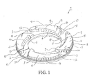
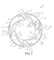
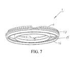
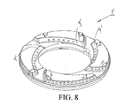
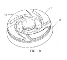
- the present invention provides a burner fire cap 1 or 1' for a gas cooktop, which includes a substantially annular cover body 2.
- a plane 3 is configured on the cover body.
- At least two bosses 4 protruding from the plane are distributed on the plane in a peripheral direction of the fire cap.
- Fire holes are disposed on the bosses.
- the burner fire cap for a gas cooktop in the present invention at least two bosses are disposed and the fire holes are disposed on the bosses.
- the distribution of fire holes on the fire cap is changed, thereby improving the uniformity for heating a bottom of a utensil by using a burner having the fire cap.
- recesses 15 having the same number and substantially corresponding shape as the bosses are disposed on a rear side of the cover body.
- the recesses disposed at corresponding positions on the rear side of the cover body further facilitate changing the processing of conventionally distributed fire holes.
- the bosses are evenly distributed on the plane.
- the distribution of fire holes on the bosses is improved as compared with conventional distribution of fire holes, and the fire holes are further evenly distributed in the peripheral direction of the cover body, thereby further improving a heating effect.
- each boss in order to facilitate the mechanically processing of the burner fire cap for a gas cooktop according to the present invention and improve the distribution of fire holes on a second boss side surface 9 or 9', that is, to facilitate processing of the fire holes, each boss at least has a first boss side surface 8 with fire holes distributed thereon and a second boss side surface 9 or 9' forming a first included angle ⁇ with the first boss side surface 8 and having fire holes distributed thereon.
- each boss further has a third boss side surface 10 forming a second included angle ⁇ with the first boss side surface 8 and having fire holes distributed thereon.
- the distribution areas for fire holes are enlarged, and due to the configured inclined surface, the processing of fire holes distributed on the third boss side surface 10 becomes more convenient.
- top surfaces 11 of all the bosses are located at the same horizontal plane.
- the number of the bosses is two to eight and the bosses are evenly distributed on the plane 3.
- the number of the bosses is three or four and the bosses are evenly distributed on the plane 3.
- outer-ring fire holes 5 are distributed on the first boss side surface 8
- inner-ring fire holes 6 are distributed on the second boss side surface 9
- middle fire holes 7 are distributed on the third boss side surface 10.
- the middle fire holes distributed between the outer-ring fire holes 5 and the inner-ring fire holes 6 are added in the design of the present invention, such that the heating efficiency of the burner fire cap for a gas cooktop of the present invention is further enhanced.
- the disposed middle fire holes 7 and/or inner-ring fire holes 6 enable flames from such fire holes to at least partially reach a space right above the cover body.
- an auxiliary air supply channel 12 is formed between adjacent bosses 4, which supplies oxygen gas for the combustion of a mixed gas of fuel gas and air. Therefore, the heating efficiency of the fire cap with the above structure is further improved.
- the auxiliary air supply channel 12 is mainly formed between the second boss side surface 9 and the third boss side surface 10 on the adjacent bosses 4.
- the fire holes distributed on the second boss side surface 9 and the third boss side surface 10 are closer to a center point of the fire cap, that is, located in the inner side. Therefore, the auxiliary air supply channel is formed between the second boss side surface 9 and the third boss side surface 10, such that the combustion of fuel gas at the fire holes distributed on the two side surfaces is more sufficient, thereby enhancing an overall heating efficiency of the fire cap.
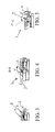
- the first boss side surface 8 inclines for approximately an angle ⁇ relative to the plane 3, and 90° ⁇ 135°.
- the first boss side surface 8 inclines for an angle ⁇ of 110° relative to the plane 3.
- the second boss side surface inclines for approximately an angle ⁇ relative to the plane 3, and 120° ⁇ 150°.
- An optimal drilling angle ⁇ is 135°.
- the third boss side surface inclines for approximately an angle ⁇ relative to the plane 3, and 100° ⁇ 150°.
- the drilling angle ⁇ may be 120° ⁇ 125°, and most preferably, the angle ⁇ may be 123.7°.
- the directions for disposing the fire holes on the boss side surfaces are also improved, that is, the directions of the fire holes 5, 6, 7 are substantially perpendicular to the boss side surfaces 8, 9, 10.
- a thickness of the fire cap is relatively small, that is, between 12 cm and 15 cm.
- the thickness of the fire cap of the present invention is much smaller than that of the burner fire cap for a gas cooktop in the prior art. Therefore, a volume of the whole fire cap is decreased, the weight thereof becomes smaller, and the consumed material is reduced.
- the thickness of the fire cap is between 14 cm and 15 cm. In this embodiment, most preferably, the thickness of the fire cap is 14.3 cm.
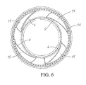
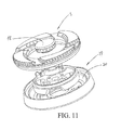
- the present invention further provides a gas cooktop burner, which includes a gas mixing chamber member 19 disposed with a gas cavity 20, a small fire cap 18 operated together with a small gas-mixing cavity of the gas mixing chamber member 19, and the fire cap 1 or 1 ' of the present invention.
- the fire cap 1 or 1' is operated together with the gas cavity 20.
- the gas cooktop burner of the present invention uses the fire cap of the present invention, the gas cooktop burner of the present invention has corresponding advantages in terms of manufacturing and/or performance and/or material cost.
Landscapes
- Engineering & Computer Science (AREA)
- Chemical & Material Sciences (AREA)
- Combustion & Propulsion (AREA)
- Mechanical Engineering (AREA)
- General Engineering & Computer Science (AREA)
- Gas Burners (AREA)
- Cookers (AREA)
- Baking, Grill, Roasting (AREA)
- Electric Ovens (AREA)
Applications Claiming Priority (1)
| Application Number | Priority Date | Filing Date | Title |
|---|---|---|---|
| CN200810244322A CN101737782B (zh) | 2008-11-21 | 2008-11-21 | 燃气灶炉头火盖及带有该种火盖的炉头 |
Publications (3)
| Publication Number | Publication Date |
|---|---|
| EP2189718A2 true EP2189718A2 (de) | 2010-05-26 |
| EP2189718A3 EP2189718A3 (de) | 2017-06-21 |
| EP2189718B1 EP2189718B1 (de) | 2019-01-09 |
Family
ID=41668338
Family Applications (1)
| Application Number | Title | Priority Date | Filing Date |
|---|---|---|---|
| EP09176541.2A Active EP2189718B1 (de) | 2008-11-21 | 2009-11-19 | Brennerflammenkappe und Brenner für ein Gaskochfeld |
Country Status (4)
| Country | Link |
|---|---|
| US (1) | US8220450B2 (de) |
| EP (1) | EP2189718B1 (de) |
| CN (1) | CN101737782B (de) |
| TR (1) | TR201900742T4 (de) |
Cited By (7)
| Publication number | Priority date | Publication date | Assignee | Title |
|---|---|---|---|---|
| CN102287822A (zh) * | 2010-06-18 | 2011-12-21 | 博西华电器(江苏)有限公司 | 燃气灶用火盖、带有该种火盖的燃烧器及燃气灶 |
| EP2290287A3 (de) * | 2009-08-27 | 2014-08-20 | BSH Bosch und Siemens Hausgeräte GmbH | Brennerkappe für Gasherde und Gasherd-Brenner mit einer solchen Brennerkappe |
| CN106224958A (zh) * | 2016-09-27 | 2016-12-14 | 宁波方太厨具有限公司 | 一种家用燃气灶具燃烧器 |
| CN108443883A (zh) * | 2018-04-08 | 2018-08-24 | 广东美的厨房电器制造有限公司 | 火盖、燃烧器和燃气灶具 |
| CN110107900A (zh) * | 2019-05-25 | 2019-08-09 | 江门奇焰节能燃气具有限公司 | 一种燃气混合燃烧器 |
| WO2021094151A1 (en) * | 2019-11-13 | 2021-05-20 | BSH Hausgeräte GmbH | Liquid heating vessel |
| CN113063143A (zh) * | 2020-01-02 | 2021-07-02 | 宁波方太厨具有限公司 | 火盖、含其的燃烧器和燃气灶具 |
Families Citing this family (31)
| Publication number | Priority date | Publication date | Assignee | Title |
|---|---|---|---|---|
| CN102116476B (zh) * | 2011-02-14 | 2013-02-13 | 杭州老板电器股份有限公司 | 一种高效节能环保型燃烧器 |
| ITAN20120036A1 (it) * | 2011-04-19 | 2012-10-20 | Somipress Societa Metalli Iniett Ati S P A | Fornello a gas con fiamma rivolta verso l'interno. |
| CN102367958A (zh) * | 2011-10-13 | 2012-03-07 | 四川长虹电器股份有限公司 | 一种高热负荷的燃气灶具 |
| BRPI1105163A2 (pt) * | 2011-12-15 | 2013-10-08 | Whirlpool Sa | Dispositivo difusor de gás de chama para equipamentos de cocção |
| US9541294B2 (en) | 2013-08-06 | 2017-01-10 | Whirlpool Corporation | Inner swirling flame gas burner |
| CN104748117A (zh) * | 2015-02-12 | 2015-07-01 | 上海林内有限公司 | 花瓣式大火盖及安装有花瓣式大火盖的燃烧器 |
| CN104696962A (zh) * | 2015-03-09 | 2015-06-10 | 广东美的厨房电器制造有限公司 | 外火盖及燃烧器及燃气灶具 |
| US9989248B2 (en) | 2015-09-08 | 2018-06-05 | Whirlpool Corporation | Premixed stamped inner flames burner with eccentric injection venturi |
| USD787041S1 (en) | 2015-09-17 | 2017-05-16 | Whirlpool Corporation | Gas burner |
| US10837651B2 (en) | 2015-09-24 | 2020-11-17 | Whirlpool Corporation | Oven cavity connector for operating power accessory trays for cooking appliance |
| CN105202542A (zh) * | 2015-10-17 | 2015-12-30 | 肖阳 | 一种高效燃烧器 |
| US11777190B2 (en) | 2015-12-29 | 2023-10-03 | Whirlpool Corporation | Appliance including an antenna using a portion of appliance as a ground plane |
| US10145568B2 (en) | 2016-06-27 | 2018-12-04 | Whirlpool Corporation | High efficiency high power inner flame burner |
| US10436451B2 (en) | 2016-10-06 | 2019-10-08 | Whirlpool Corporation | Cap to change inner flame burner to vertical flame |
| CN106678797B (zh) * | 2016-12-15 | 2019-10-01 | 广东美的厨房电器制造有限公司 | 燃烧器和燃气灶具 |
| US10627113B2 (en) | 2016-12-29 | 2020-04-21 | Whirlpool Corporation | Distributed vertical flame burner |
| CA3052191C (en) | 2017-02-01 | 2022-01-04 | Vt Burner Technologies Inc. | Tiered burner |
| US10551056B2 (en) * | 2017-02-23 | 2020-02-04 | Whirlpool Corporation | Burner base |
| US10451290B2 (en) | 2017-03-07 | 2019-10-22 | Whirlpool Corporation | Forced convection steam assembly |
| US10660162B2 (en) | 2017-03-16 | 2020-05-19 | Whirlpool Corporation | Power delivery system for an induction cooktop with multi-output inverters |
| ES2702788A1 (es) * | 2017-09-05 | 2019-03-05 | Bsh Electrodomesticos Espana Sa | Soporte de olla, punto de coccion a gas, y procedimiento para fabricar un soporte de olla |
| CN107726318B (zh) * | 2017-10-17 | 2023-03-10 | 珠海格力电器股份有限公司 | 燃烧器及包括其的燃气灶 |
| US10627116B2 (en) | 2018-06-26 | 2020-04-21 | Whirlpool Corporation | Ventilation system for cooking appliance |
| US10619862B2 (en) | 2018-06-28 | 2020-04-14 | Whirlpool Corporation | Frontal cooling towers for a ventilation system of a cooking appliance |
| US10837652B2 (en) | 2018-07-18 | 2020-11-17 | Whirlpool Corporation | Appliance secondary door |
| CN109681876A (zh) * | 2019-01-21 | 2019-04-26 | 广东万家乐厨房科技有限公司 | 一种切槽式外火盖及燃烧器 |
| CN111473327B (zh) * | 2020-03-30 | 2022-04-15 | 宁波方太厨具有限公司 | 一种离心式燃烧器 |
| CN111735052B (zh) * | 2020-07-17 | 2023-04-07 | 佛山市顺德区美的洗涤电器制造有限公司 | 火盖、燃烧器及燃气灶具 |
| US11940148B2 (en) * | 2021-10-28 | 2024-03-26 | Electrolux Appliances Aktiebolag | Multi injection dual ring gas burner for domestic gas cooking units |
| US11821636B2 (en) * | 2022-02-18 | 2023-11-21 | Haohong Electric Technology (Hubei) Co., Ltd. | Outdoor portable gas stove |
| EP4230917A1 (de) * | 2022-02-18 | 2023-08-23 | Haohong Electric Technology (Hubei) Co., Ltd. | Tragbarer gasherd für den aussenbereich |
Family Cites Families (10)
| Publication number | Priority date | Publication date | Assignee | Title |
|---|---|---|---|---|
| JPS61144321U (de) * | 1985-02-28 | 1986-09-05 | ||
| JPS6347687Y2 (de) * | 1985-02-28 | 1988-12-08 | ||
| US5842849A (en) * | 1997-09-05 | 1998-12-01 | Huang; Hsu-Sheng | Gas burner |
| US6742514B1 (en) * | 2002-06-07 | 2004-06-01 | Eastman Outdoors | Burner assembly, outdoor stove including same, and stove kit |
| JP3984238B2 (ja) * | 2004-04-23 | 2007-10-03 | リンナイ株式会社 | コンロ用バーナ |
| ITVE20050004A1 (it) * | 2005-01-20 | 2006-07-21 | Ohg Defendi S R L | Bruciatore a gas per apparecchiature di cottura. |
| JP3812585B2 (ja) * | 2005-03-18 | 2006-08-23 | 松下電器産業株式会社 | こんろバーナ |
| CN2859238Y (zh) * | 2005-10-28 | 2007-01-17 | 廖珈 | 一种燃气灶火盖 |
| CN201129728Y (zh) * | 2007-09-25 | 2008-10-08 | 明协华 | 分火器 |
| CN201225623Y (zh) * | 2008-06-25 | 2009-04-22 | 成都前锋电子电器集团股份有限公司 | 燃气灶具分火器 |
-
2008
- 2008-11-21 CN CN200810244322A patent/CN101737782B/zh active Active
-
2009
- 2009-11-19 EP EP09176541.2A patent/EP2189718B1/de active Active
- 2009-11-19 TR TR2019/00742T patent/TR201900742T4/tr unknown
- 2009-11-20 US US12/622,538 patent/US8220450B2/en not_active Expired - Fee Related
Cited By (13)
| Publication number | Priority date | Publication date | Assignee | Title |
|---|---|---|---|---|
| EP2290287A3 (de) * | 2009-08-27 | 2014-08-20 | BSH Bosch und Siemens Hausgeräte GmbH | Brennerkappe für Gasherde und Gasherd-Brenner mit einer solchen Brennerkappe |
| CN102287822A (zh) * | 2010-06-18 | 2011-12-21 | 博西华电器(江苏)有限公司 | 燃气灶用火盖、带有该种火盖的燃烧器及燃气灶 |
| CN102287822B (zh) * | 2010-06-18 | 2015-11-25 | 博西华电器(江苏)有限公司 | 燃气灶用火盖、带有该种火盖的燃烧器及燃气灶 |
| EP2397757A3 (de) * | 2010-06-18 | 2017-11-15 | BSH Hausgeräte GmbH | Brennerkappe für Gasherde, Brenner und Gasherd |
| CN106224958A (zh) * | 2016-09-27 | 2016-12-14 | 宁波方太厨具有限公司 | 一种家用燃气灶具燃烧器 |
| CN106224958B (zh) * | 2016-09-27 | 2018-05-29 | 宁波方太厨具有限公司 | 一种家用燃气灶具燃烧器 |
| CN108443883A (zh) * | 2018-04-08 | 2018-08-24 | 广东美的厨房电器制造有限公司 | 火盖、燃烧器和燃气灶具 |
| CN108443883B (zh) * | 2018-04-08 | 2024-03-08 | 广东美的厨房电器制造有限公司 | 火盖、燃烧器和燃气灶具 |
| CN110107900A (zh) * | 2019-05-25 | 2019-08-09 | 江门奇焰节能燃气具有限公司 | 一种燃气混合燃烧器 |
| CN110107900B (zh) * | 2019-05-25 | 2023-10-27 | 杨锡奇 | 一种燃气混合燃烧器 |
| WO2021094151A1 (en) * | 2019-11-13 | 2021-05-20 | BSH Hausgeräte GmbH | Liquid heating vessel |
| CN113063143A (zh) * | 2020-01-02 | 2021-07-02 | 宁波方太厨具有限公司 | 火盖、含其的燃烧器和燃气灶具 |
| CN113063143B (zh) * | 2020-01-02 | 2022-08-09 | 宁波方太厨具有限公司 | 火盖、含其的燃烧器和燃气灶具 |
Also Published As
| Publication number | Publication date |
|---|---|
| CN101737782B (zh) | 2012-08-29 |
| EP2189718B1 (de) | 2019-01-09 |
| TR201900742T4 (tr) | 2019-02-21 |
| US8220450B2 (en) | 2012-07-17 |
| CN101737782A (zh) | 2010-06-16 |
| US20100126496A1 (en) | 2010-05-27 |
| EP2189718A3 (de) | 2017-06-21 |
Similar Documents
| Publication | Publication Date | Title |
|---|---|---|
| EP2189718B1 (de) | Brennerflammenkappe und Brenner für ein Gaskochfeld | |
| US7628609B2 (en) | Hub and spoke burner with flame stability | |
| EP2122248B1 (de) | Gasbrennersystem für kochgeräte | |
| US20180209657A1 (en) | Diffusion cap burner for gas cooking appliance | |
| US11421889B2 (en) | Cap to change inner flame burner to vertical flame | |
| ATE412853T1 (de) | Gasbrenner | |
| US9206986B2 (en) | Burner | |
| CA2628165A1 (en) | Cooling and combustion airflow supply system for a gas range | |
| US20080050687A1 (en) | Gas burner assembly | |
| EP2799771B1 (de) | Gasbrenner, insbesondere für Kochgerät | |
| US6886552B2 (en) | Cooktop grate with flame clearance | |
| US20060254574A1 (en) | Apparatus for ventilation in a radiation gas range | |
| CN108870389B (zh) | 燃气灶用燃烧器的火盖、炉头、燃烧器及燃气灶 | |
| JP6653529B2 (ja) | ガスバーナ | |
| CN108105770A (zh) | 一种超薄型燃烧器及燃气灶 | |
| CN210801170U (zh) | 一种分气盘及灶具燃烧器 | |
| US7077644B1 (en) | Advanced commercial range burner | |
| CN206846709U (zh) | 灶具用燃烧器 | |
| KR101751059B1 (ko) | 빌트인 타입 가스오븐레인지 | |
| US11268692B2 (en) | Gas cooking grate with integral burner | |
| JP2002181310A (ja) | コンロバーナ | |
| CN221629814U (zh) | 一种燃气灶具 | |
| CN219318436U (zh) | 燃烧器 | |
| CN222669996U (zh) | 一种齿形上进风燃烧器 | |
| EP3410011A1 (de) | Gasbrenneranordnung, vorzugsweise für ein gaskochfeld |
Legal Events
| Date | Code | Title | Description |
|---|---|---|---|
| PUAI | Public reference made under article 153(3) epc to a published international application that has entered the european phase |
Free format text: ORIGINAL CODE: 0009012 |
|
| 17P | Request for examination filed |
Effective date: 20091119 |
|
| AK | Designated contracting states |
Kind code of ref document: A2 Designated state(s): AT BE BG CH CY CZ DE DK EE ES FI FR GB GR HR HU IE IS IT LI LT LU LV MC MK MT NL NO PL PT RO SE SI SK SM TR |
|
| RIN1 | Information on inventor provided before grant (corrected) |
Inventor name: LUO, HAITAO Inventor name: MIAO, WEIWEI Inventor name: ZHANG, SHENZHOU |
|
| RAP1 | Party data changed (applicant data changed or rights of an application transferred) |
Owner name: BSH HAUSGERAETE GMBH |
|
| PUAL | Search report despatched |
Free format text: ORIGINAL CODE: 0009013 |
|
| AK | Designated contracting states |
Kind code of ref document: A3 Designated state(s): AT BE BG CH CY CZ DE DK EE ES FI FR GB GR HR HU IE IS IT LI LT LU LV MC MK MT NL NO PL PT RO SE SI SK SM TR |
|
| RIC1 | Information provided on ipc code assigned before grant |
Ipc: F23D 14/06 20060101AFI20170512BHEP |
|
| STAA | Information on the status of an ep patent application or granted ep patent |
Free format text: STATUS: EXAMINATION IS IN PROGRESS |
|
| 17Q | First examination report despatched |
Effective date: 20170810 |
|
| RBV | Designated contracting states (corrected) |
Designated state(s): AT BE BG CH CY CZ DE DK EE ES FI FR GB GR HR HU IE IS IT LI LT LU LV MC MK MT NL NO PL PT RO SE SI SK SM TR |
|
| GRAP | Despatch of communication of intention to grant a patent |
Free format text: ORIGINAL CODE: EPIDOSNIGR1 |
|
| STAA | Information on the status of an ep patent application or granted ep patent |
Free format text: STATUS: GRANT OF PATENT IS INTENDED |
|
| INTG | Intention to grant announced |
Effective date: 20180615 |
|
| GRAS | Grant fee paid |
Free format text: ORIGINAL CODE: EPIDOSNIGR3 |
|
| GRAA | (expected) grant |
Free format text: ORIGINAL CODE: 0009210 |
|
| STAA | Information on the status of an ep patent application or granted ep patent |
Free format text: STATUS: THE PATENT HAS BEEN GRANTED |
|
| AK | Designated contracting states |
Kind code of ref document: B1 Designated state(s): AT BE BG CH CY CZ DE DK EE ES FI FR GB GR HR HU IE IS IT LI LT LU LV MC MK MT NL NO PL PT RO SE SI SK SM TR |
|
| REG | Reference to a national code |
Ref country code: GB Ref legal event code: FG4D |
|
| REG | Reference to a national code |
Ref country code: CH Ref legal event code: EP Ref country code: AT Ref legal event code: REF Ref document number: 1087772 Country of ref document: AT Kind code of ref document: T Effective date: 20190115 |
|
| REG | Reference to a national code |
Ref country code: DE Ref legal event code: R096 Ref document number: 602009056602 Country of ref document: DE |
|
| REG | Reference to a national code |
Ref country code: IE Ref legal event code: FG4D |
|
| REG | Reference to a national code |
Ref country code: NL Ref legal event code: MP Effective date: 20190109 |
|
| REG | Reference to a national code |
Ref country code: LT Ref legal event code: MG4D |
|
| PG25 | Lapsed in a contracting state [announced via postgrant information from national office to epo] |
Ref country code: NL Free format text: LAPSE BECAUSE OF FAILURE TO SUBMIT A TRANSLATION OF THE DESCRIPTION OR TO PAY THE FEE WITHIN THE PRESCRIBED TIME-LIMIT Effective date: 20190109 |
|
| REG | Reference to a national code |
Ref country code: AT Ref legal event code: MK05 Ref document number: 1087772 Country of ref document: AT Kind code of ref document: T Effective date: 20190109 |
|
| PG25 | Lapsed in a contracting state [announced via postgrant information from national office to epo] |
Ref country code: LT Free format text: LAPSE BECAUSE OF FAILURE TO SUBMIT A TRANSLATION OF THE DESCRIPTION OR TO PAY THE FEE WITHIN THE PRESCRIBED TIME-LIMIT Effective date: 20190109 Ref country code: SE Free format text: LAPSE BECAUSE OF FAILURE TO SUBMIT A TRANSLATION OF THE DESCRIPTION OR TO PAY THE FEE WITHIN THE PRESCRIBED TIME-LIMIT Effective date: 20190109 Ref country code: FI Free format text: LAPSE BECAUSE OF FAILURE TO SUBMIT A TRANSLATION OF THE DESCRIPTION OR TO PAY THE FEE WITHIN THE PRESCRIBED TIME-LIMIT Effective date: 20190109 Ref country code: NO Free format text: LAPSE BECAUSE OF FAILURE TO SUBMIT A TRANSLATION OF THE DESCRIPTION OR TO PAY THE FEE WITHIN THE PRESCRIBED TIME-LIMIT Effective date: 20190409 Ref country code: PT Free format text: LAPSE BECAUSE OF FAILURE TO SUBMIT A TRANSLATION OF THE DESCRIPTION OR TO PAY THE FEE WITHIN THE PRESCRIBED TIME-LIMIT Effective date: 20190509 Ref country code: ES Free format text: LAPSE BECAUSE OF FAILURE TO SUBMIT A TRANSLATION OF THE DESCRIPTION OR TO PAY THE FEE WITHIN THE PRESCRIBED TIME-LIMIT Effective date: 20190109 Ref country code: PL Free format text: LAPSE BECAUSE OF FAILURE TO SUBMIT A TRANSLATION OF THE DESCRIPTION OR TO PAY THE FEE WITHIN THE PRESCRIBED TIME-LIMIT Effective date: 20190109 |
|
| PG25 | Lapsed in a contracting state [announced via postgrant information from national office to epo] |
Ref country code: IS Free format text: LAPSE BECAUSE OF FAILURE TO SUBMIT A TRANSLATION OF THE DESCRIPTION OR TO PAY THE FEE WITHIN THE PRESCRIBED TIME-LIMIT Effective date: 20190509 Ref country code: LV Free format text: LAPSE BECAUSE OF FAILURE TO SUBMIT A TRANSLATION OF THE DESCRIPTION OR TO PAY THE FEE WITHIN THE PRESCRIBED TIME-LIMIT Effective date: 20190109 Ref country code: HR Free format text: LAPSE BECAUSE OF FAILURE TO SUBMIT A TRANSLATION OF THE DESCRIPTION OR TO PAY THE FEE WITHIN THE PRESCRIBED TIME-LIMIT Effective date: 20190109 Ref country code: BG Free format text: LAPSE BECAUSE OF FAILURE TO SUBMIT A TRANSLATION OF THE DESCRIPTION OR TO PAY THE FEE WITHIN THE PRESCRIBED TIME-LIMIT Effective date: 20190409 |
|
| REG | Reference to a national code |
Ref country code: DE Ref legal event code: R097 Ref document number: 602009056602 Country of ref document: DE |
|
| PG25 | Lapsed in a contracting state [announced via postgrant information from national office to epo] |
Ref country code: CZ Free format text: LAPSE BECAUSE OF FAILURE TO SUBMIT A TRANSLATION OF THE DESCRIPTION OR TO PAY THE FEE WITHIN THE PRESCRIBED TIME-LIMIT Effective date: 20190109 Ref country code: AT Free format text: LAPSE BECAUSE OF FAILURE TO SUBMIT A TRANSLATION OF THE DESCRIPTION OR TO PAY THE FEE WITHIN THE PRESCRIBED TIME-LIMIT Effective date: 20190109 Ref country code: RO Free format text: LAPSE BECAUSE OF FAILURE TO SUBMIT A TRANSLATION OF THE DESCRIPTION OR TO PAY THE FEE WITHIN THE PRESCRIBED TIME-LIMIT Effective date: 20190109 Ref country code: EE Free format text: LAPSE BECAUSE OF FAILURE TO SUBMIT A TRANSLATION OF THE DESCRIPTION OR TO PAY THE FEE WITHIN THE PRESCRIBED TIME-LIMIT Effective date: 20190109 Ref country code: DK Free format text: LAPSE BECAUSE OF FAILURE TO SUBMIT A TRANSLATION OF THE DESCRIPTION OR TO PAY THE FEE WITHIN THE PRESCRIBED TIME-LIMIT Effective date: 20190109 Ref country code: SK Free format text: LAPSE BECAUSE OF FAILURE TO SUBMIT A TRANSLATION OF THE DESCRIPTION OR TO PAY THE FEE WITHIN THE PRESCRIBED TIME-LIMIT Effective date: 20190109 |
|
| PLBE | No opposition filed within time limit |
Free format text: ORIGINAL CODE: 0009261 |
|
| STAA | Information on the status of an ep patent application or granted ep patent |
Free format text: STATUS: NO OPPOSITION FILED WITHIN TIME LIMIT |
|
| PG25 | Lapsed in a contracting state [announced via postgrant information from national office to epo] |
Ref country code: SM Free format text: LAPSE BECAUSE OF FAILURE TO SUBMIT A TRANSLATION OF THE DESCRIPTION OR TO PAY THE FEE WITHIN THE PRESCRIBED TIME-LIMIT Effective date: 20190109 |
|
| 26N | No opposition filed |
Effective date: 20191010 |
|
| PGFP | Annual fee paid to national office [announced via postgrant information from national office to epo] |
Ref country code: DE Payment date: 20191130 Year of fee payment: 11 |
|
| PG25 | Lapsed in a contracting state [announced via postgrant information from national office to epo] |
Ref country code: SI Free format text: LAPSE BECAUSE OF FAILURE TO SUBMIT A TRANSLATION OF THE DESCRIPTION OR TO PAY THE FEE WITHIN THE PRESCRIBED TIME-LIMIT Effective date: 20190109 |
|
| PGFP | Annual fee paid to national office [announced via postgrant information from national office to epo] |
Ref country code: TR Payment date: 20191118 Year of fee payment: 11 |
|
| REG | Reference to a national code |
Ref country code: CH Ref legal event code: PL |
|
| PG25 | Lapsed in a contracting state [announced via postgrant information from national office to epo] |
Ref country code: LI Free format text: LAPSE BECAUSE OF NON-PAYMENT OF DUE FEES Effective date: 20191130 Ref country code: MC Free format text: LAPSE BECAUSE OF FAILURE TO SUBMIT A TRANSLATION OF THE DESCRIPTION OR TO PAY THE FEE WITHIN THE PRESCRIBED TIME-LIMIT Effective date: 20190109 Ref country code: CH Free format text: LAPSE BECAUSE OF NON-PAYMENT OF DUE FEES Effective date: 20191130 Ref country code: LU Free format text: LAPSE BECAUSE OF NON-PAYMENT OF DUE FEES Effective date: 20191119 |
|
| REG | Reference to a national code |
Ref country code: BE Ref legal event code: MM Effective date: 20191130 |
|
| GBPC | Gb: european patent ceased through non-payment of renewal fee |
Effective date: 20191119 |
|
| PG25 | Lapsed in a contracting state [announced via postgrant information from national office to epo] |
Ref country code: FR Free format text: LAPSE BECAUSE OF NON-PAYMENT OF DUE FEES Effective date: 20191130 Ref country code: GB Free format text: LAPSE BECAUSE OF NON-PAYMENT OF DUE FEES Effective date: 20191119 Ref country code: IE Free format text: LAPSE BECAUSE OF NON-PAYMENT OF DUE FEES Effective date: 20191119 |
|
| PG25 | Lapsed in a contracting state [announced via postgrant information from national office to epo] |
Ref country code: BE Free format text: LAPSE BECAUSE OF NON-PAYMENT OF DUE FEES Effective date: 20191130 |
|
| PG25 | Lapsed in a contracting state [announced via postgrant information from national office to epo] |
Ref country code: CY Free format text: LAPSE BECAUSE OF FAILURE TO SUBMIT A TRANSLATION OF THE DESCRIPTION OR TO PAY THE FEE WITHIN THE PRESCRIBED TIME-LIMIT Effective date: 20190109 |
|
| REG | Reference to a national code |
Ref country code: DE Ref legal event code: R119 Ref document number: 602009056602 Country of ref document: DE |
|
| PG25 | Lapsed in a contracting state [announced via postgrant information from national office to epo] |
Ref country code: GR Free format text: LAPSE BECAUSE OF FAILURE TO SUBMIT A TRANSLATION OF THE DESCRIPTION OR TO PAY THE FEE WITHIN THE PRESCRIBED TIME-LIMIT Effective date: 20190109 |
|
| PG25 | Lapsed in a contracting state [announced via postgrant information from national office to epo] |
Ref country code: HU Free format text: LAPSE BECAUSE OF FAILURE TO SUBMIT A TRANSLATION OF THE DESCRIPTION OR TO PAY THE FEE WITHIN THE PRESCRIBED TIME-LIMIT; INVALID AB INITIO Effective date: 20091119 Ref country code: MT Free format text: LAPSE BECAUSE OF FAILURE TO SUBMIT A TRANSLATION OF THE DESCRIPTION OR TO PAY THE FEE WITHIN THE PRESCRIBED TIME-LIMIT Effective date: 20190109 |
|
| PG25 | Lapsed in a contracting state [announced via postgrant information from national office to epo] |
Ref country code: DE Free format text: LAPSE BECAUSE OF NON-PAYMENT OF DUE FEES Effective date: 20210601 |
|
| PG25 | Lapsed in a contracting state [announced via postgrant information from national office to epo] |
Ref country code: TR Free format text: LAPSE BECAUSE OF NON-PAYMENT OF DUE FEES Effective date: 20201119 Ref country code: MK Free format text: LAPSE BECAUSE OF FAILURE TO SUBMIT A TRANSLATION OF THE DESCRIPTION OR TO PAY THE FEE WITHIN THE PRESCRIBED TIME-LIMIT Effective date: 20190109 |
|
| PGFP | Annual fee paid to national office [announced via postgrant information from national office to epo] |
Ref country code: IT Payment date: 20241129 Year of fee payment: 16 |