EP2187105B1 - Suck-back valve - Google Patents
Suck-back valve Download PDFInfo
- Publication number
- EP2187105B1 EP2187105B1 EP08830960A EP08830960A EP2187105B1 EP 2187105 B1 EP2187105 B1 EP 2187105B1 EP 08830960 A EP08830960 A EP 08830960A EP 08830960 A EP08830960 A EP 08830960A EP 2187105 B1 EP2187105 B1 EP 2187105B1
- Authority
- EP
- European Patent Office
- Prior art keywords
- valve
- suck
- shaft portion
- piston
- open
- Prior art date
- Legal status (The legal status is an assumption and is not a legal conclusion. Google has not performed a legal analysis and makes no representation as to the accuracy of the status listed.)
- Active
Links
- 239000012530 fluid Substances 0.000 claims abstract description 39
- 238000009434 installation Methods 0.000 description 6
- 239000000126 substance Substances 0.000 description 5
- 230000007257 malfunction Effects 0.000 description 4
- 239000007788 liquid Substances 0.000 description 2
- 230000007423 decrease Effects 0.000 description 1
- 230000003247 decreasing effect Effects 0.000 description 1
- 238000000034 method Methods 0.000 description 1
- 238000012986 modification Methods 0.000 description 1
- 230000004048 modification Effects 0.000 description 1
- 230000002093 peripheral effect Effects 0.000 description 1
Images


Classifications
-
- F—MECHANICAL ENGINEERING; LIGHTING; HEATING; WEAPONS; BLASTING
- F16—ENGINEERING ELEMENTS AND UNITS; GENERAL MEASURES FOR PRODUCING AND MAINTAINING EFFECTIVE FUNCTIONING OF MACHINES OR INSTALLATIONS; THERMAL INSULATION IN GENERAL
- F16K—VALVES; TAPS; COCKS; ACTUATING-FLOATS; DEVICES FOR VENTING OR AERATING
- F16K23/00—Valves for preventing drip from nozzles
Definitions
- the present invention relates to a suck-back valve having a suck-back function that prevents the occurrence of leakage during the fully closing operation of an open/close valve.
- a separate valve exclusively for "suck-back" has been additionally provided to prevent leakage (dripping of the fluid) that occurs during the fully closing operation.
- Such a valve exclusively for suck-back operates synchronously with the closing operation of the open/close valve, and it is possible to prevent leakage by actuating a diaphragm in a direction that increases the volume of a suck-back chamber, thus sucking liquid on the outlet side to the suck-back chamber side (for example refer to Patent Citation 1 or 2).
- a suck-back valve in which an open/close valve is provided with a suck-back function, i.e., a suck-back valve in which the open/close valve and the valve exclusively for suck-back are integrated, in order to reduce the installation space and to solve the problem of synchronization.
- a suck-back valve it is desirable to include a measure against malfunction of the suck-back function caused by adhesion of the fluid to be handled thereby.
- the present invention has been conceived in light of the above situation, and an object thereof is to provide suck-back valve equipment with an open/close valve having a suck-back function.
- a suck-back valve according to the present invention is a suck-back valve in which a piston and a valve body that receive fluid pressure for the open/close operation are linked via a shaft portion, and an open/close valve that carries out the open/close operation of the valve body by the fluid pressure is provided with a suck-back function, wherein a suck-back chamber formed in a valve internal channel of the open/close valve and an open/close operation portion that operates the piston are separated by a diaphragm that is linked to and integrally operates with the shaft portion; the shaft portion is divided into a valve-body-side shaft portion and a piston-side shaft portion, and the piston-side shaft portion is loosely fitted to the valve-body-side shaft portion, allowing for independent movement in an axial direction; and during the closing operation of the valve body, a two-step operation is carried out, including a valve closing operation step in which the shaft portion, along with the piston and the di
- the suck-back chamber formed in the valve internal channel of the open/close valve and the open/close operation portion that operates the piston are separated by the diaphragm that is linked to and integrally operates with the shaft portion; the shaft portion is divided into the valve-body-side shaft portion and the piston-side shaft portion, and the piston-side shaft portion is loosely fitted to the valve-body-side shaft portion, allowing for independent movement in the axial direction; and during the valve closing operation, a two-step operation is carried out, including the valve closing operation step in which the shaft portion, along with the piston and the diaphragm, moves to the fully closed position of the valve body, and the suck-back operation step in which the piston-side shaft portion moves with the piston and the diaphragm to increase the volume of the suck-back chamber. Therefore, with the shared use of the actuator, a single suck-back valve can carry out opening/closing of the valve and suck-back for preventing leak
- the loose-fitting portion in which the piston-side shaft portion is loosely fitted to the valve-body-side shaft portion, be provided closer to the open/close operation portion side than to the diaphragm. Accordingly, the loose-fitting portion can be prevented from coming into contact with the fluid flowing in the valve internal channel.
- the outer periphery of the loose-fitting portion be covered with bellows that are integral with the diaphragm. Accordingly, the loose-fitting portion can be smoothly operated without coming into contact with the fluid flowing in the valve internal channel, and moreover, the operation range thereof can be increased.
- suck-back level adjusting portion which regulates the amount of axial movement of the piston-side shaft portion. Accordingly, the suck-back level can be appropriately adjusted to be optimized in accordance with various conditions.
- the present invention described above it becomes possible to achieve the open/close operation of the valve and the suck-back function with a single actuator, and the suck-back valve provided with the suck-back function in the open/close valve can be provided.
- the installation space can be reduced and the problem of synchronizing the actuator can be solved.
- the loose-fitting portion that carries out the suck-back operation is configured so as not to come in contact with the fluid flowing in the valve internal channel, the fluid to be handled, such as chemicals, does not adhere to the loose-fitting portion. Therefore, it is possible to prevent the occurrence of malfunction of the suck-back function and to increase the reliability of the suck-back valve.
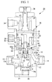
- a suck-back valve SV shown in Figs. 1 to 3 is integrally formed of an actuator 30 for the open/close operation and an open/close valve 10 that is installed in a channel through which fluid, such as chemicals, flows and that is provided with a suck-back function for preventing leakage when fully closing.
- a piston 31 of the actuator 30, which receives air pressure for operating the actuator (fluid pressure for the open/close operation), is linked via a shaft portion 50 to a valve body 11 which carries out the open/close operation of the open/close valve 10, and the open/close valve 10, which carries out the open/close operation using air pressure, is provided with the suck-back function.
- Fig. 1 shows the open/close valve 10 in a fully open state
- Fig. 2 shows a state before operating the suck-back function, with the open/close valve 10 fully closed
- Fig. 3 shows a state in which the suck-back function is operated from the state in Fig. 2 .
- valve main body (casing) 12 is provided with a fluid inlet 13 and a fluid outlet 14, and the valve body 11, which opens/closes a fluid channel 16, is disposed in an internal space 15 of the valve main body 12.
- a suck-back chamber 17 communicating with the internal space 15 via the fluid channel 16 is formed above the fluid channel 16.
- the suck-back chamber 17 serves as part of a channel for flowing fluid in the open/close valve 10 (hereinafter, referred to as "valve internal channel”) and is also the space in which part of the shaft portion 50 linked to the valve body 11 is disposed.
- the suck-back chamber 17 is also the space that achieves the suck-back function by increasing the volume through operation of a diaphragm 60 described later.
- the fluid inlet 13 communicates with the internal space 15 via an inlet channel 13a
- the fluid outlet 14 communicates with the suck-back chamber 17 via the outlet channel 14a.
- the valve body 11 described above vertically moves in the internal space 15 along with the piston 31 and the shaft portion 50, thereby opening/closing the fluid channel 16 formed in the open/close valve 10.
- a seat portion 18 is provided at the top-end portion of the internal space 15, in other words, at the inlet portion of the fluid channel 16, a seat portion 18 is provided.
- the fluid channel 16 is closed when the valve body 11 moves upward coming into close contact with the seat portion 18, and the fluid channel 16 is opened when the valve body 11 moves downward away from the seat portion 18.
- valve internal channel formed in the open/close valve 10 is arranged, in order of the flowing direction in the open/close valve 10, in the fluid inlet 13, the inlet channel 13a, the internal space 15, the fluid channel 16, the suck-back chamber 17, the outlet channel 14a, and the fluid outlet 14.
- reference number 19 in the drawings is a lower diaphragm whose base portion 19a is linked to the lower portion of the valve body 11, 20 is a coil spring that biases the base portion 19a upward, and 21 is an exhaust channel. Note that, because the lower portion of the valve body 11 is narrowed to reduce the diameter thereof, the diameter of the lower diaphragm 19 can be reduced.
- the piston 31 is disposed in a cylinder portion 33 of an internal space formed in an actuator main body 32, and the open/close valve 10 is open/close operated by supplying air pressure to either side of the cylinder portion 33 partitioned by the piston 31.
- the actuator main body 32 is provided with two air pressure supply ports 34 and 35, one of which can be selected for use.
- the air pressure supply port 34 disposed at the top supplies air pressure to the upper surface side of the piston 31 that axially slides in the cylinder portion 33
- the air pressure supply port 35 disposed at the bottom supplies air pressure to the bottom surface side of the piston 31 that axially slides in the cylinder portion 33.
- air pressure is supplied from the top air pressure supply port 34, and the lower air pressure supply port 35 is closed by a plug 36.
- the piston 31 described above is constantly biased upwards (the direction in which the valve body 11 is closed) by a coil spring 37, and therefore, the illustrated open/close valve 10 is a normally closed type that is constantly closed in a state without the supply of air pressure. That is, although the valve body 11 is constantly in a closed state due to bias from the coil spring 37, when the air pressure is supplied from the air pressure supply port 34 to press down the piston 31, overcoming the bias of the coil springs 20 and 37, the valve body 11 linked via the shaft portion 50 is pressed down. As a result, the valve body 11 separates from the seat portion 18, shifting into an open state.
- the actuator 30 described above is provided with a suck-back level adjusting portion that regulates the amount of axial movement of the shaft portion 50 on the piston 31 side.
- the suck-back level adjusting portion is a threaded shaft 39 that moves in an axial direction by operation of a handle 38, which makes it possible to adjust the amount by which a tip portion 39a protrudes into the cylinder portion 33.
- reference numeral 40 in the figures is an installation space for a coil spring and is used as needed when, for example, selecting and changing the operation method (normally closed or normally opened) of the open/closed valve 10 and the actuator 30.
- the shaft portion 50 is a member that links the piston 31 and the valve body 11 and that opens/closes the valve body 11 of the open/close valve 10 by operation of the actuator 30.
- the shaft portion 50 is provided with a piston shaft portion 51 provided at the bottom surface of the piston 31 and a valve body shaft portion 22 provided at an upper portion of the valve body 11.
- a loosely-fitted shaft portion 52 is threaded to the piston shaft portion 51 at a shaft center position so as to protrude downward from the bottom surface.
- the loosely-fitted shaft portion 52 is provided with an exhaust channel 53 that communicates to the shaft side surface from the bottom-end surface 52a through the shaft center position.
- the exhaust channel 53 serves as a channel for allowing air in a loose-fitting portion 54, which is narrowed by the loosely-fitted shaft portion 52 to make the suck-back function described later operate smoothly, to flow out to the atmosphere. Note that the air that flows out to the exterior of the loose-fitting portion 54 through the exhaust channel 53 flows out to the atmosphere through a through-hole 41 provided in the actuator main body 32.
- a base portion 61 of the diaphragm 60 is linked to the top surface of a valve body shaft portion 22 by threading thereto.
- the base portion 61 is integrally provided with bellows 62 that covers the circumference of the loosely-fitted shaft portion 52, and additionally, the top-end portion of the bellows 62 is provided with a top-end base portion 63a engaged to the loosely-fitted shaft portion 52.
- the top-end base portion 63a is engaged with the loosely-fitted shaft portion 52 by means of a corresponding protrusion and depression so as to integrally move in the axial direction.
- the top-end base portion 63a is integrally provided with a diaphragm main body 63 that extends horizontally.
- an outer peripheral portion of the diaphragm main body 63 is provided with an outer edge portion 64 that is secured by being interposed between the open/close valve 10 and the actuator 30. Therefore, the diaphragm main body 63 is configured such that the diaphragm 63 and the loosely-fitted shaft portion 52 integrally operate while covering a top portion of the suck-back chamber 17, separating it from the space on the actuator 30 side.
- the loose-fitting portion 54 which makes it possible for the loosely-fitted shaft portion 52 to move in the axial direction, is formed inside the bellows 62. Therefore, the loose-fitting portion 54 is provided closer to the actuator 30 side than to the diaphragm 60, and the fluid that flows inside the open/close valve 10 is completely separated from a driving unit of the actuator 30 by the diaphragm 60. That is, the diaphragm 60 is provided so as to separate the actuator 30 and the suck-back chamber 17 on the open/close valve 10 side, and the loosely-fitted shaft portion 52 of the actuator 30 is configured to operate in the region without contacting the fluid, such as chemicals.
- the suck-back chamber 17 formed in the valve internal channel of the open/close valve 10 and the actuator 30 that operates the piston 31 are separated by the diaphragm 60 which is linked to and integrally operates with the shaft portion 50.
- the shaft portion 50 is divided into a valve-body-side shaft portion constituted of the valve body shaft portion 22 and a piston-side shaft portion constituted of the piston shaft portion 51 and the loosely-fitted shaft portion 52, and the loosely-fitted shaft portion 52 of the piston-side shaft portion is loosely fitted to the base portion 61 of the diaphragm 60 integrally linked to the valve-body-side shaft portion 22, allowing for independent movement in the axial direction.
- a two-step operation is carried out, including a valve closing operation step in which the shaft portion 50, along with the piston 31 and the diaphragm 60, moves to the fully closed position of the valve body 11, and a suck-back operation step in which the piston shaft portion 51 and the loosely-fitted shaft portion 52 of the piston-side shaft portion move with the piston 31 and the diaphragm main body 63 of the diaphragm 60 to increase the volume of the suck-back chamber 17.
- a valve closing operation step in which the shaft portion 50, along with the piston 31 and the diaphragm 60, moves to the fully closed position of the valve body 11
- a suck-back operation step in which the piston shaft portion 51 and the loosely-fitted shaft portion 52 of the piston-side shaft portion move with the piston 31 and the diaphragm main body 63 of the diaphragm 60 to increase the volume of the suck-back chamber 17.
- the valve body 11 is prevented from moving further up, and thus, the loosely-fitted shaft portion 52 separates from the base portion 61, moving upward with the piston 31 and the shaft portion 50.
- the top-end base portion 63a of the diaphragm main body 63 is pulled up along with the loosely-fitted shaft portion 52, and thereby, as shown in Fig. 3 , the diaphragm main body 63 is deformed, increasing the volume of the suck-back chamber 17.
- the increase in the volume of the suck-back chamber 17 also ends, completing the suck-back operation step.
- the volume of the suck-back chamber 17 is thus increased, in the valve internal channel of the open/close valve 10 which is divided by closing the valve body 11, fluid remaining on the downstream side of the valve body 11 is sucked towards the suck-back chamber 17, thereby making it possible to prevent leakage.
- the open/close operation of the open/close valve 10 and the suck-back function due to the diaphragm 60 can be achieved by a single actuator 30. That is, with the present invention, because the suck-back valve SV provided with the suck-back function can be provided in the open/close valve 10, with the suck-back valve SV wherein the function of the open/close valve and the suck-back function are integrated, it becomes possible to reduce the installation space, and the problem of synchronizing the actuator 30 is also solved.
- the configuration thereof is such that the loosely-fitted shaft portion 52 that carries out the suck-back function is separated by the bellows 62 so as not to come in contact with the fluid flowing in the valve internal channel, fluid to be handled, such as chemicals, does not adhere to the loose-fitting portion. Therefore, it is possible to prevent the occurrence of a malfunction of the suck-back function and to increase the reliability of the suck-back valve SV.
- the loose-fitting portion 54 is covered with the bellows 62; however, it is not limited to this. Nonetheless, because the bellows 62 easily extends and contracts in the axial direction, the operation of the loosely-fitted shaft portion 52 can be smoothly carried out. Note that, depending on the stroke of the loosely-fitted shaft portion 52, a suitable deformation may be provided instead of an extending/contracting portion such as the bellows 62. Note that the present invention is not limited to the above-described embodiment, and various modifications are possible, limited only by the appended claims.
Applications Claiming Priority (2)
| Application Number | Priority Date | Filing Date | Title |
|---|---|---|---|
| JP2007236182A JP5009107B2 (ja) | 2007-09-12 | 2007-09-12 | サックバックバルブ |
| PCT/JP2008/066168 WO2009034944A1 (ja) | 2007-09-12 | 2008-09-08 | サックバックバルブ |
Publications (3)
| Publication Number | Publication Date |
|---|---|
| EP2187105A1 EP2187105A1 (en) | 2010-05-19 |
| EP2187105A4 EP2187105A4 (en) | 2011-08-31 |
| EP2187105B1 true EP2187105B1 (en) | 2012-03-14 |
Family
ID=40451952
Family Applications (1)
| Application Number | Title | Priority Date | Filing Date |
|---|---|---|---|
| EP08830960A Active EP2187105B1 (en) | 2007-09-12 | 2008-09-08 | Suck-back valve |
Country Status (6)
| Country | Link |
|---|---|
| US (1) | US8602383B2 (ko) |
| EP (1) | EP2187105B1 (ko) |
| JP (1) | JP5009107B2 (ko) |
| KR (1) | KR101504378B1 (ko) |
| AT (1) | ATE549559T1 (ko) |
| WO (1) | WO2009034944A1 (ko) |
Families Citing this family (9)
| Publication number | Priority date | Publication date | Assignee | Title |
|---|---|---|---|---|
| FR2848854B1 (fr) | 2002-12-24 | 2005-03-18 | Coletica | Particules comprenant un biopolymere degradable sous l'effet d'une onde electromagnetique telle qu'emise par un rayonnement solaire |
| JP5247298B2 (ja) * | 2008-08-18 | 2013-07-24 | サーパス工業株式会社 | サックバックバルブ |
| JP5546026B2 (ja) * | 2011-08-08 | 2014-07-09 | Ckd株式会社 | 液垂れ防止バルブ |
| US10307857B2 (en) | 2014-09-09 | 2019-06-04 | Proteus Industries Inc. | Systems and methods for coolant drawback |
| JP6923220B2 (ja) * | 2016-11-30 | 2021-08-18 | 株式会社フジキン | バルブ装置、このバルブ装置を用いた流量制御方法および半導体製造方法 |
| JP6978927B2 (ja) | 2017-12-19 | 2021-12-08 | サーパス工業株式会社 | バルブ |
| KR102594753B1 (ko) * | 2018-12-24 | 2023-10-27 | 충북대학교 산학협력단 | 흡입 기능을 갖는 유량 제어 밸브 |
| JP7300710B2 (ja) * | 2019-05-10 | 2023-06-30 | サーパス工業株式会社 | サックバックバルブ |
| KR102583555B1 (ko) | 2020-12-09 | 2023-09-26 | 세메스 주식회사 | 처리액 공급 유닛을 포함하는 기판 처리 장치 및 기판 처리 방법 |
Family Cites Families (14)
| Publication number | Priority date | Publication date | Assignee | Title |
|---|---|---|---|---|
| JPS59177929A (ja) * | 1983-03-28 | 1984-10-08 | Canon Inc | サツクバツクポンプ |
| JPH0325086U (ko) * | 1989-07-21 | 1991-03-14 | ||
| JP4081620B2 (ja) * | 1997-03-05 | 2008-04-30 | Smc株式会社 | サックバックバルブ |
| JP4035666B2 (ja) * | 1997-03-14 | 2008-01-23 | Smc株式会社 | サックバックバルブ |
| JP3822957B2 (ja) * | 1997-08-04 | 2006-09-20 | シーケーディ株式会社 | エアオペレイト弁 |
| JP3997535B2 (ja) * | 1998-08-31 | 2007-10-24 | Smc株式会社 | サックバックバルブ |
| JP3493322B2 (ja) * | 1998-09-25 | 2004-02-03 | Smc株式会社 | 液だれ防止方法およびシステム |
| JP2002139161A (ja) * | 2000-11-06 | 2002-05-17 | Smc Corp | 二方弁 |
| JP4970661B2 (ja) | 2001-04-23 | 2012-07-11 | シーケーディ株式会社 | サックバックバルブ |
| JP4142883B2 (ja) * | 2002-03-20 | 2008-09-03 | シーケーディ株式会社 | 薬液弁 |
| US6837484B2 (en) * | 2002-07-10 | 2005-01-04 | Saint-Gobain Performance Plastics, Inc. | Anti-pumping dispense valve |
| EP1601900A2 (en) * | 2003-03-07 | 2005-12-07 | Swagelok Company | Valve with adjustable stop |
| JP4035728B2 (ja) * | 2003-07-07 | 2008-01-23 | Smc株式会社 | サックバックバルブ |
| JP5247298B2 (ja) * | 2008-08-18 | 2013-07-24 | サーパス工業株式会社 | サックバックバルブ |
-
2007
- 2007-09-12 JP JP2007236182A patent/JP5009107B2/ja active Active
-
2008
- 2008-09-08 US US12/675,885 patent/US8602383B2/en active Active
- 2008-09-08 WO PCT/JP2008/066168 patent/WO2009034944A1/ja active Application Filing
- 2008-09-08 AT AT08830960T patent/ATE549559T1/de active
- 2008-09-08 EP EP08830960A patent/EP2187105B1/en active Active
- 2008-09-08 KR KR1020107005180A patent/KR101504378B1/ko active IP Right Grant
Also Published As
| Publication number | Publication date |
|---|---|
| EP2187105A1 (en) | 2010-05-19 |
| JP5009107B2 (ja) | 2012-08-22 |
| EP2187105A4 (en) | 2011-08-31 |
| KR20100066499A (ko) | 2010-06-17 |
| KR101504378B1 (ko) | 2015-03-19 |
| US20100230626A1 (en) | 2010-09-16 |
| WO2009034944A1 (ja) | 2009-03-19 |
| US8602383B2 (en) | 2013-12-10 |
| ATE549559T1 (de) | 2012-03-15 |
| JP2009068568A (ja) | 2009-04-02 |
Similar Documents
| Publication | Publication Date | Title |
|---|---|---|
| EP2187105B1 (en) | Suck-back valve | |
| EP2157343B1 (en) | Suck-back valve | |
| US10767773B2 (en) | Check valve | |
| US8342201B2 (en) | Pressure reducing valve | |
| JP5553514B2 (ja) | 可変容量型圧縮機用制御弁 | |
| EP2308602B1 (en) | Liquid dispensing module | |
| EP1712792A2 (en) | Control valve for variable capacity compressors | |
| JP2008309255A (ja) | 逃がし弁 | |
| JP6770320B2 (ja) | 環状ポペット逆止弁を備えた調節弁 | |
| WO2014132529A1 (ja) | レベリングバルブ | |
| KR101506485B1 (ko) | 역흡입 밸브 시스템 및 그 폐쇄밸브 동작제어방법 | |
| WO2014012414A1 (en) | Valve assembly | |
| EP3660367B1 (en) | Cylinder device with sequence valve | |
| JP2013079692A (ja) | 流量制御弁 | |
| CN109630745B (zh) | 用于气动或液压阀的阀驱动系统 | |
| CN117396694A (zh) | 时机调整阀及具备时机调整阀的回吸阀 | |
| EP3680491A1 (en) | Control valve | |
| US20230417341A1 (en) | Valve system | |
| JP4424674B2 (ja) | 減圧弁 | |
| KR102037084B1 (ko) | 체크밸브 | |
| CN114909492A (zh) | 一种用于阀的密封控制结构以及阀装置 | |
| KR20190044170A (ko) | 체크밸브 | |
| JPH11304037A (ja) | バルブ | |
| WO2017208208A1 (en) | Valve for use with a pneumatic clutch actuation system |
Legal Events
| Date | Code | Title | Description |
|---|---|---|---|
| PUAI | Public reference made under article 153(3) epc to a published international application that has entered the european phase |
Free format text: ORIGINAL CODE: 0009012 |
|
| 17P | Request for examination filed |
Effective date: 20100308 |
|
| AK | Designated contracting states |
Kind code of ref document: A1 Designated state(s): AT BE BG CH CY CZ DE DK EE ES FI FR GB GR HR HU IE IS IT LI LT LU LV MC MT NL NO PL PT RO SE SI SK TR |
|
| AX | Request for extension of the european patent |
Extension state: AL BA MK RS |
|
| DAX | Request for extension of the european patent (deleted) | ||
| A4 | Supplementary search report drawn up and despatched |
Effective date: 20110728 |
|
| RIC1 | Information provided on ipc code assigned before grant |
Ipc: F16K 23/00 20060101AFI20110722BHEP Ipc: F16K 31/122 20060101ALI20110722BHEP |
|
| GRAP | Despatch of communication of intention to grant a patent |
Free format text: ORIGINAL CODE: EPIDOSNIGR1 |
|
| GRAS | Grant fee paid |
Free format text: ORIGINAL CODE: EPIDOSNIGR3 |
|
| GRAA | (expected) grant |
Free format text: ORIGINAL CODE: 0009210 |
|
| AK | Designated contracting states |
Kind code of ref document: B1 Designated state(s): AT BE BG CH CY CZ DE DK EE ES FI FR GB GR HR HU IE IS IT LI LT LU LV MC MT NL NO PL PT RO SE SI SK TR |
|
| REG | Reference to a national code |
Ref country code: GB Ref legal event code: FG4D |
|
| REG | Reference to a national code |
Ref country code: AT Ref legal event code: REF Ref document number: 549559 Country of ref document: AT Kind code of ref document: T Effective date: 20120315 Ref country code: CH Ref legal event code: EP |
|
| REG | Reference to a national code |
Ref country code: IE Ref legal event code: FG4D |
|
| REG | Reference to a national code |
Ref country code: DE Ref legal event code: R096 Ref document number: 602008014168 Country of ref document: DE Effective date: 20120510 |
|
| REG | Reference to a national code |
Ref country code: NL Ref legal event code: VDEP Effective date: 20120314 |
|
| PG25 | Lapsed in a contracting state [announced via postgrant information from national office to epo] |
Ref country code: LT Free format text: LAPSE BECAUSE OF FAILURE TO SUBMIT A TRANSLATION OF THE DESCRIPTION OR TO PAY THE FEE WITHIN THE PRESCRIBED TIME-LIMIT Effective date: 20120314 Ref country code: HR Free format text: LAPSE BECAUSE OF FAILURE TO SUBMIT A TRANSLATION OF THE DESCRIPTION OR TO PAY THE FEE WITHIN THE PRESCRIBED TIME-LIMIT Effective date: 20120314 Ref country code: NO Free format text: LAPSE BECAUSE OF FAILURE TO SUBMIT A TRANSLATION OF THE DESCRIPTION OR TO PAY THE FEE WITHIN THE PRESCRIBED TIME-LIMIT Effective date: 20120614 |
|
| LTIE | Lt: invalidation of european patent or patent extension |
Effective date: 20120314 |
|
| PG25 | Lapsed in a contracting state [announced via postgrant information from national office to epo] |
Ref country code: LV Free format text: LAPSE BECAUSE OF FAILURE TO SUBMIT A TRANSLATION OF THE DESCRIPTION OR TO PAY THE FEE WITHIN THE PRESCRIBED TIME-LIMIT Effective date: 20120314 Ref country code: FI Free format text: LAPSE BECAUSE OF FAILURE TO SUBMIT A TRANSLATION OF THE DESCRIPTION OR TO PAY THE FEE WITHIN THE PRESCRIBED TIME-LIMIT Effective date: 20120314 Ref country code: GR Free format text: LAPSE BECAUSE OF FAILURE TO SUBMIT A TRANSLATION OF THE DESCRIPTION OR TO PAY THE FEE WITHIN THE PRESCRIBED TIME-LIMIT Effective date: 20120615 |
|
| REG | Reference to a national code |
Ref country code: AT Ref legal event code: MK05 Ref document number: 549559 Country of ref document: AT Kind code of ref document: T Effective date: 20120314 |
|
| PG25 | Lapsed in a contracting state [announced via postgrant information from national office to epo] |
Ref country code: CY Free format text: LAPSE BECAUSE OF FAILURE TO SUBMIT A TRANSLATION OF THE DESCRIPTION OR TO PAY THE FEE WITHIN THE PRESCRIBED TIME-LIMIT Effective date: 20120314 |
|
| PG25 | Lapsed in a contracting state [announced via postgrant information from national office to epo] |
Ref country code: EE Free format text: LAPSE BECAUSE OF FAILURE TO SUBMIT A TRANSLATION OF THE DESCRIPTION OR TO PAY THE FEE WITHIN THE PRESCRIBED TIME-LIMIT Effective date: 20120314 Ref country code: RO Free format text: LAPSE BECAUSE OF FAILURE TO SUBMIT A TRANSLATION OF THE DESCRIPTION OR TO PAY THE FEE WITHIN THE PRESCRIBED TIME-LIMIT Effective date: 20120314 Ref country code: SI Free format text: LAPSE BECAUSE OF FAILURE TO SUBMIT A TRANSLATION OF THE DESCRIPTION OR TO PAY THE FEE WITHIN THE PRESCRIBED TIME-LIMIT Effective date: 20120314 Ref country code: PL Free format text: LAPSE BECAUSE OF FAILURE TO SUBMIT A TRANSLATION OF THE DESCRIPTION OR TO PAY THE FEE WITHIN THE PRESCRIBED TIME-LIMIT Effective date: 20120314 Ref country code: BE Free format text: LAPSE BECAUSE OF FAILURE TO SUBMIT A TRANSLATION OF THE DESCRIPTION OR TO PAY THE FEE WITHIN THE PRESCRIBED TIME-LIMIT Effective date: 20120314 Ref country code: CZ Free format text: LAPSE BECAUSE OF FAILURE TO SUBMIT A TRANSLATION OF THE DESCRIPTION OR TO PAY THE FEE WITHIN THE PRESCRIBED TIME-LIMIT Effective date: 20120314 Ref country code: IS Free format text: LAPSE BECAUSE OF FAILURE TO SUBMIT A TRANSLATION OF THE DESCRIPTION OR TO PAY THE FEE WITHIN THE PRESCRIBED TIME-LIMIT Effective date: 20120714 Ref country code: SE Free format text: LAPSE BECAUSE OF FAILURE TO SUBMIT A TRANSLATION OF THE DESCRIPTION OR TO PAY THE FEE WITHIN THE PRESCRIBED TIME-LIMIT Effective date: 20120314 |
|
| PG25 | Lapsed in a contracting state [announced via postgrant information from national office to epo] |
Ref country code: SK Free format text: LAPSE BECAUSE OF FAILURE TO SUBMIT A TRANSLATION OF THE DESCRIPTION OR TO PAY THE FEE WITHIN THE PRESCRIBED TIME-LIMIT Effective date: 20120314 Ref country code: PT Free format text: LAPSE BECAUSE OF FAILURE TO SUBMIT A TRANSLATION OF THE DESCRIPTION OR TO PAY THE FEE WITHIN THE PRESCRIBED TIME-LIMIT Effective date: 20120716 |
|
| PLBE | No opposition filed within time limit |
Free format text: ORIGINAL CODE: 0009261 |
|
| STAA | Information on the status of an ep patent application or granted ep patent |
Free format text: STATUS: NO OPPOSITION FILED WITHIN TIME LIMIT |
|
| PG25 | Lapsed in a contracting state [announced via postgrant information from national office to epo] |
Ref country code: DK Free format text: LAPSE BECAUSE OF FAILURE TO SUBMIT A TRANSLATION OF THE DESCRIPTION OR TO PAY THE FEE WITHIN THE PRESCRIBED TIME-LIMIT Effective date: 20120314 Ref country code: AT Free format text: LAPSE BECAUSE OF FAILURE TO SUBMIT A TRANSLATION OF THE DESCRIPTION OR TO PAY THE FEE WITHIN THE PRESCRIBED TIME-LIMIT Effective date: 20120314 Ref country code: NL Free format text: LAPSE BECAUSE OF FAILURE TO SUBMIT A TRANSLATION OF THE DESCRIPTION OR TO PAY THE FEE WITHIN THE PRESCRIBED TIME-LIMIT Effective date: 20120314 |
|
| 26N | No opposition filed |
Effective date: 20121217 |
|
| PG25 | Lapsed in a contracting state [announced via postgrant information from national office to epo] |
Ref country code: IT Free format text: LAPSE BECAUSE OF FAILURE TO SUBMIT A TRANSLATION OF THE DESCRIPTION OR TO PAY THE FEE WITHIN THE PRESCRIBED TIME-LIMIT Effective date: 20120314 |
|
| REG | Reference to a national code |
Ref country code: DE Ref legal event code: R097 Ref document number: 602008014168 Country of ref document: DE Effective date: 20121217 |
|
| PG25 | Lapsed in a contracting state [announced via postgrant information from national office to epo] |
Ref country code: ES Free format text: LAPSE BECAUSE OF FAILURE TO SUBMIT A TRANSLATION OF THE DESCRIPTION OR TO PAY THE FEE WITHIN THE PRESCRIBED TIME-LIMIT Effective date: 20120625 Ref country code: MC Free format text: LAPSE BECAUSE OF NON-PAYMENT OF DUE FEES Effective date: 20120930 |
|
| REG | Reference to a national code |
Ref country code: CH Ref legal event code: PL |
|
| GBPC | Gb: european patent ceased through non-payment of renewal fee |
Effective date: 20120908 |
|
| REG | Reference to a national code |
Ref country code: IE Ref legal event code: MM4A |
|
| REG | Reference to a national code |
Ref country code: FR Ref legal event code: ST Effective date: 20130531 |
|
| PG25 | Lapsed in a contracting state [announced via postgrant information from national office to epo] |
Ref country code: CH Free format text: LAPSE BECAUSE OF NON-PAYMENT OF DUE FEES Effective date: 20120930 Ref country code: LI Free format text: LAPSE BECAUSE OF NON-PAYMENT OF DUE FEES Effective date: 20120930 Ref country code: GB Free format text: LAPSE BECAUSE OF NON-PAYMENT OF DUE FEES Effective date: 20120908 Ref country code: BG Free format text: LAPSE BECAUSE OF FAILURE TO SUBMIT A TRANSLATION OF THE DESCRIPTION OR TO PAY THE FEE WITHIN THE PRESCRIBED TIME-LIMIT Effective date: 20120614 Ref country code: IE Free format text: LAPSE BECAUSE OF NON-PAYMENT OF DUE FEES Effective date: 20120908 |
|
| PG25 | Lapsed in a contracting state [announced via postgrant information from national office to epo] |
Ref country code: FR Free format text: LAPSE BECAUSE OF NON-PAYMENT OF DUE FEES Effective date: 20121001 |
|
| PG25 | Lapsed in a contracting state [announced via postgrant information from national office to epo] |
Ref country code: MT Free format text: LAPSE BECAUSE OF FAILURE TO SUBMIT A TRANSLATION OF THE DESCRIPTION OR TO PAY THE FEE WITHIN THE PRESCRIBED TIME-LIMIT Effective date: 20120314 |
|
| PG25 | Lapsed in a contracting state [announced via postgrant information from national office to epo] |
Ref country code: TR Free format text: LAPSE BECAUSE OF FAILURE TO SUBMIT A TRANSLATION OF THE DESCRIPTION OR TO PAY THE FEE WITHIN THE PRESCRIBED TIME-LIMIT Effective date: 20120314 |
|
| PG25 | Lapsed in a contracting state [announced via postgrant information from national office to epo] |
Ref country code: LU Free format text: LAPSE BECAUSE OF NON-PAYMENT OF DUE FEES Effective date: 20120908 |
|
| PG25 | Lapsed in a contracting state [announced via postgrant information from national office to epo] |
Ref country code: HU Free format text: LAPSE BECAUSE OF FAILURE TO SUBMIT A TRANSLATION OF THE DESCRIPTION OR TO PAY THE FEE WITHIN THE PRESCRIBED TIME-LIMIT Effective date: 20080908 |
|
| PGFP | Annual fee paid to national office [announced via postgrant information from national office to epo] |
Ref country code: DE Payment date: 20230920 Year of fee payment: 16 |