EP2186935A1 - Gasbeheizter Wäschetrockner mit Heizungseinrichtung - Google Patents
Gasbeheizter Wäschetrockner mit Heizungseinrichtung Download PDFInfo
- Publication number
- EP2186935A1 EP2186935A1 EP10001075A EP10001075A EP2186935A1 EP 2186935 A1 EP2186935 A1 EP 2186935A1 EP 10001075 A EP10001075 A EP 10001075A EP 10001075 A EP10001075 A EP 10001075A EP 2186935 A1 EP2186935 A1 EP 2186935A1
- Authority
- EP
- European Patent Office
- Prior art keywords
- heating channel
- air
- gas
- channel
- heating device
- Prior art date
- Legal status (The legal status is an assumption and is not a legal conclusion. Google has not performed a legal analysis and makes no representation as to the accuracy of the status listed.)
- Granted
Links
- 238000010438 heat treatment Methods 0.000 title claims abstract description 125
- 239000007789 gas Substances 0.000 claims abstract description 36
- 238000000034 method Methods 0.000 claims abstract description 20
- 238000002485 combustion reaction Methods 0.000 claims description 9
- 238000011144 upstream manufacturing Methods 0.000 claims description 4
- 239000007858 starting material Substances 0.000 description 4
- 230000015572 biosynthetic process Effects 0.000 description 3
- 238000010276 construction Methods 0.000 description 2
- 230000002093 peripheral effect Effects 0.000 description 2
- UGFAIRIUMAVXCW-UHFFFAOYSA-N Carbon monoxide Chemical compound [O+]#[C-] UGFAIRIUMAVXCW-UHFFFAOYSA-N 0.000 description 1
- 239000011324 bead Substances 0.000 description 1
- 229910002091 carbon monoxide Inorganic materials 0.000 description 1
- 238000001816 cooling Methods 0.000 description 1
- 238000001035 drying Methods 0.000 description 1
- 230000000694 effects Effects 0.000 description 1
- 239000003344 environmental pollutant Substances 0.000 description 1
- 239000002737 fuel gas Substances 0.000 description 1
- 238000009434 installation Methods 0.000 description 1
- 238000004519 manufacturing process Methods 0.000 description 1
- 238000002156 mixing Methods 0.000 description 1
- 238000012986 modification Methods 0.000 description 1
- 230000004048 modification Effects 0.000 description 1
- 231100000719 pollutant Toxicity 0.000 description 1
- 230000005855 radiation Effects 0.000 description 1
- 230000000630 rising effect Effects 0.000 description 1
- 230000006641 stabilisation Effects 0.000 description 1
- 238000011105 stabilization Methods 0.000 description 1
Images


Classifications
-
- D—TEXTILES; PAPER
- D06—TREATMENT OF TEXTILES OR THE LIKE; LAUNDERING; FLEXIBLE MATERIALS NOT OTHERWISE PROVIDED FOR
- D06F—LAUNDERING, DRYING, IRONING, PRESSING OR FOLDING TEXTILE ARTICLES
- D06F58/00—Domestic laundry dryers
- D06F58/20—General details of domestic laundry dryers
- D06F58/26—Heating arrangements, e.g. gas heating equipment
- D06F58/263—Gas heating equipment
-
- F—MECHANICAL ENGINEERING; LIGHTING; HEATING; WEAPONS; BLASTING
- F26—DRYING
- F26B—DRYING SOLID MATERIALS OR OBJECTS BY REMOVING LIQUID THEREFROM
- F26B23/00—Heating arrangements
- F26B23/02—Heating arrangements using combustion heating
-
- D—TEXTILES; PAPER
- D06—TREATMENT OF TEXTILES OR THE LIKE; LAUNDERING; FLEXIBLE MATERIALS NOT OTHERWISE PROVIDED FOR
- D06F—LAUNDERING, DRYING, IRONING, PRESSING OR FOLDING TEXTILE ARTICLES
- D06F2103/00—Parameters monitored or detected for the control of domestic laundry washing machines, washer-dryers or laundry dryers
- D06F2103/28—Air properties
- D06F2103/32—Temperature
-
- D—TEXTILES; PAPER
- D06—TREATMENT OF TEXTILES OR THE LIKE; LAUNDERING; FLEXIBLE MATERIALS NOT OTHERWISE PROVIDED FOR
- D06F—LAUNDERING, DRYING, IRONING, PRESSING OR FOLDING TEXTILE ARTICLES
- D06F58/00—Domestic laundry dryers
- D06F58/32—Control of operations performed in domestic laundry dryers
- D06F58/34—Control of operations performed in domestic laundry dryers characterised by the purpose or target of the control
- D06F58/50—Responding to irregular working conditions, e.g. malfunctioning of blowers
Definitions
- Gas-heated clothes dryer with a heating device with a gas burner and a valve with a gas nozzle on the primary air can be supplied to the flame, a flame surrounding tubular heating channel at its inlet secondary air is supplied as combustion air and at the outlet opening of the hot gases tertiary air is mixed, the heating channel with its outlet opening opens into an air channel for the process air.
- the known burner is a burner with partial premixing of fuel gas and air.
- the so-called primary air is sucked in by injector action of the gas nozzles.
- the secondary air component and the tertiary air component are sucked in via the process air blower.
- the secondary air enters the heating channel at the burner head and flows around the flame to prevent contact of the flame with the walls of the heating channel or the combustion chamber and thus the heat transfer to the housing.
- the tertiary air enters at the end of the flame via holes in the lateral surface of the heating channel.
- the Tertiär Kunststoffö Maschinentechnischen are arranged relative to the cross section of the heating channel in the lower half-shell, so that contact of the flame is avoided with the Schukanalwand.
- the tertiary air also serves to lower the temperature of the hot air at the inlet to the process air duct to the process air temperature.
- the control of the gas supply via a valve and a Zündflammen- or Zündfunkenüberwachung. It has been found that despite the design measures such as the obliquely upwardly rising arrangement of the heating channel and the formation of the tertiary air supply in the region of the flame end in the lower half shell of the heating channel still no particularly low-emission combustion can be achieved.
- a heating device for a tumble dryer with a first heating channel and a second heating channel is known. Both heating channels have circular cross sections, wherein the second heating channel relative to the first heating channel has an enlarged cross-section.
- the burner head of the burner protrudes into the inlet opening of the first heating channel, wherein the axial center line of the burner is below the center line of the first heating channel.
- the outlet opening of the first heating channel opens eccentrically offset downwards into the inlet opening of the second heating channel.
- the first heating channel also has a guide for entering at the inlet opening secondary air, which extends in the flow direction from a middle upper portion of the first heating channel to the outlet opening of the first heating channel sloping.
- a similar gas heated clothes dryer with heater is from the US 3,826,607 known.
- two heating channels are present, wherein the outlet opening of the first heating channel, in which the flame opening of the burner opens, has a smaller cross section than the inlet opening of the second channel, wherein the first channel protrudes with its outlet opening into the second channel.
- first and second heating channel requires a higher outlay in the production as well as in the assembly of the heating device in a tumble dryer.
- the component consisting of first and second heating channel is to be adjusted as a separate component during assembly exactly to the burner, so that in fact the desired formation of the air flow is achieved.
- the invention is therefore based on the object to provide a gas-fired heating device, which can be positioned with minimal installation effort in a tumble dryer.
- the achievable with the present invention consist in addition to the particularly uniform temperature distribution in the heating channel in the compact design of the heater, which as a module with heating channel, valve, burner, igniter and temperature control in the Mounting can be fixed and aligned at a single attachment point in the tumble dryer.
- the annular aperture in the exit aperture causes the flame or hot air stream in the heating channel to be centered by the incoming secondary air and tertiary air.
- the temperature profile in the heating channel is uniform with overall low temperature without temperature peaks due to streaking. This has an advantageous effect on the pollutant content in the combustion air.
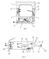
- FIG. 1 the construction of a gas-heated clothes dryer with a schematic representation of the air flow of process air and combustion air is shown.
- the tumble dryer has a rotatably mounted drum 1 for receiving the laundry to be dried, which is closed by a door 2.
- the air duct 3 to the drum inlet 4 is preceded by the gas-heated heating device 5 for heating the dry air.
- the dry air is drawn in the region of the gas-heated heating device 5 from the room air and passed as a process air flow through the drum 1.
- the process air is sucked in via the process air blower 6, which is connected downstream of the air duct 7 at the drum outlet 8, and then discharged via the exhaust air opening 9 to the environment.
- a drying program can be selected and information on security functions can be displayed.
- the gas-fired heating device is shown schematically with representation of the air supply.
- the gas burner 11 is formed with a Venturi tube 12, at its flame opening a perforated burner plate 13 is inserted.
- the primary air L1 for flame formation is drawn in via the primary air opening 14 in the region of the gas nozzle by the injector action of the gas nozzle (not shown in detail) and Venturi tube 12.
- the head of the gas burner 11 opens into the inlet opening 15 of the heating channel 16.
- the burner plate 13 is associated with a glow starter 17.
- the gas burner 11 is eccentrically offset with respect to its axial center line in the heating channel 16 (see also FIG. 4 ).
- secondary air L2 is supplied as combustion air.
- the secondary air fraction which flows past the flame 18, adjusted so that the flame 18 is modulated but not too strongly cooled. As a result, the carbon monoxide content is low.
- an annular aperture 20 is arranged in the outlet opening 19 of the heating channel 16.
- tertiary air L3 is added to the hot gases for cooling and as process air flow PL through the drum 1 (see FIG. 1 ) guided.
- the tertiary air L3 flows against the flame direction in the heating channel 16 and undergoes in the region of the diaphragm 20 mixing with the hot gases in the heating channel 16 and a deflection in the air duct for the process air PL.
- the heating device 5 is shown in a perspective view with a view of the outlet opening 19 of the heating channel 16.
- the annular aperture 20 is eccentric (see also FIG. 4 ) is arranged in the outlet opening 19.
- the aperture 20 has at the outer diameter of a tubular nozzle 21, whose outer diameter is smaller than the diameter of the heating channel 16 is dimensioned.
- This tubular nozzle 21 forms the connecting piece to the air duct 3, not shown, for the process air duct to the drum inlet 4 (see FIG. 1 ).
- the panel 20 is fixed to at least one attachment point in the adjacent generatrices of heating channel 16 and nozzle 21 in the outlet opening 19 of the heating channel 16.
- the heating channel 16 has at least one inwardly directed up to the edge of the panel 20 protruding bulge 22, the wall portion forms a further attachment point for the panel 20.
- the bulge 22 is arranged along an opening made in the circumferential direction of the heating channel 16.
- the free cross-section between the wall of the heating channel 16 and the outer diameter of the aperture 20 in the frontal outlet opening 19 forms the inflow opening for tertiary air L3.
- the inflow opening is associated in the direction of the flame 18 in the heating channel 16 into a projecting thermostat 28.
- the thermostat 28 responds to air failure and air throttling.
- a carrier 24 for the valve 25 and the gas burner 11 is in the lower region of the inlet opening 15 in extension of the lower generatrix attached.
- the carrier 24 positions the gas burner 11 in the inlet opening 15 of the heating channel 16.
- the carrier 24 is formed with a mounting foot 26 for fixing the entire heating device 5 in a tumble dryer.
- a fastening tab 27 is arranged in extension of the upper generatrix of the heating channel 16, which is the burner 11 in a vertical cross-sectional plane (see also FIG. 4 ) of the heating channel 16 fixed.
- This fastening tab 27 also carries a thermostat 29 for detecting a fault condition, which is arranged in the inflow region of the secondary air L2.
- the thermostat 29 is connected upstream of the inlet opening 15 and reacts in case of air failure and backflow of the air, for example in wind load on the exhaust port 9, if no backflow valve in the exhaust system is present or failure of the process air blower 6.
- To monitor the flame is the glow starter 17 behind a section associated in the wall of the heating channel 16, a sensor thermostat 30 which responds to infrared radiation.
- FIG. 4 shows a view of the end face of the outlet opening 19 of the heating channel 16.
- the circular center 31 of the diaphragm 20 is arranged eccentrically offset in the embodiment shown with respect to the vertical center line 32 and the horizontal center line 33 of the outlet opening 19 and the heating channel 16.
- the vertical center line of the burner plate 13 at the burner head of the gas burner and the vertical center line of the diaphragm 20 are arranged on a common vertical cross-sectional plane 34 of the heating channel 16.
- the vertical cross-sectional plane 34 is parallel to the dimension X (about 7 mm) offset from the vertical center line 32 of the outlet opening 19 of the heating channel 16 is arranged.
- the horizontal center line of the burner plate 13 is offset by the dimension Y (about 7 mm) to the center line 33 of the outlet opening.
- the thermostat 28 in the region of the inlet opening for the tertiary air L3 is positioned on the peripheral line of the heating channel 16 at the angle ⁇ to the vertical center line 32.
- the glow starter 17 is positioned on the peripheral line of the heating channel in the region of the burner plate 13 preferably at the same angle ⁇ (25 ° to 30 °) to the vertical center line 32.
- the sensor thermostat 28 associated with the glow starter 17 is preferably arranged on the circumference of the heating channel 16 in the region of the horizontal center line 33.
- the sensor thermostat 30 is positioned at an angle ⁇ (55 ° to 60 °).
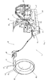
- the heating device 5 is shown in a perspective view with a view of the inlet opening of the heating channel 16 and the carrier 24 for the gas burner 11 and the valve 25.
- the carrier 24 has the in FIG. 3 already described mounting foot 26.
- the mounting foot 26 is formed as an angle connected integrally with the carrier 24, which has step-like positioning tabs 35 at its edge.
- the positioning tabs 35 engage behind a receptacle on the bottom plate (not shown in detail) of the tumble dryer and hold the entire heating device 5 in the installed position.
- the heating device 5 can still be fixed via a screw connection 36 or the like.
- the carrier 24 is formed in its longitudinal direction with a bead 37 for stabilization.
- the gas burner 11 by means of a non-detachable connection 38 (clinching, riveting) on the carrier 24 and on the fastening tab 27 is attached.
- the valve 25 is mounted as a unit by means of a releasable attachment, for example a screw (not shown in detail) on the support 24.
- the heating device 5 has in the exit region 19 of the hot air or in its connection region to the air duct 3 a positioning aid, which ensures that the heating channel 16, aperture 20 and gas burner 11 are fixed in the desired position in the device.
- the tubular socket 5 has for this purpose an approximately V-shaped receptacle 39 into which a projection 40 engages the air channel 3.
- FIG. 6 the positioning aid 39, 40 for the heating device 5 in the air duct 3 is shown enlarged.
- the in FIG. 3 illustrated thermostat 29 for detecting a fault condition can also be connected upstream of the inlet opening in another way. It is also possible, for example, a separate holder for the thermostat 29, which is associated with the inlet opening 15. Such a thermostat 29 can be integrated with little effort in all common clothes dryer with gas burners. About the thermostat, a flashback of the flame 18 is detected from the inlet opening 15. In case of failure, the gas supply to the gas burner 11 is interrupted immediately.
- the thermostat is formed with a manual reset function.
Landscapes
- Engineering & Computer Science (AREA)
- Chemical & Material Sciences (AREA)
- Combustion & Propulsion (AREA)
- Life Sciences & Earth Sciences (AREA)
- Sustainable Development (AREA)
- Mechanical Engineering (AREA)
- General Engineering & Computer Science (AREA)
- Textile Engineering (AREA)
- Detail Structures Of Washing Machines And Dryers (AREA)
- Drying Of Solid Materials (AREA)
- Accessory Of Washing/Drying Machine, Commercial Washing/Drying Machine, Other Washing/Drying Machine (AREA)
Abstract
Description
- Gasbeheizter Wäschetrockner mit einer Heizungseinrichtung mit einem Gasbrenner und einem Ventil mit Gasdüse an dem Primärluft für die Flammbildung zuführbar ist, einem die Flamme umschließenden rohrförmigen Heizkanal an dessen Eintrittsöffnung Sekundärluft als Verbrennungsluft zuführbar ist und an dessen Austrittsöffnung den heißen Gasen Tertiärluft zumischbar ist, wobei der Heizkanal mit seiner Austrittsöffnung in einen Luftkanal für die Prozessluft mündet.
- Es ist aus der
US 3,291,467 bekannt, einen Wäschetrockner mit einer gasbeheizten Heizungseinrichtung zur Erwärmung des Prozessluftstromes auszubilden. Der Brenner der Heizungseinrichtung ist der Eintrittsöffnung eines Heizkanals vorgeschaltet. Der Heizkanal ist schräg nach oben ansteigend angeordnet und folgt damit der natürlichen Ausrichtung der Flamme. Bei dem Brenner des bekannten Wäschetrockners wird dem Gas Primärluft als Verbrennungsluft vor der Brenneroberfläche zugemischt und Sekundärluft am Eingang des Heizkanals. Am Ausgang des Heizkanals wird dem heißen Gas Tertiärluft zugeführt und als Prozessluftvolumenstrom durch die Trommel geleitet. - Bei dem bekannten Brenner handelt es sich um einen Brenner mit teilweiser Vormischung von Brenngas und Luft. Die sogenannte Primärluft wird durch Injektorwirkung der Gasdüsen angesaugt. Der Sekundärluftanteil und der Tertiärluftanteil werden über das Prozessluftgebläse angesaugt. Die Sekundärluft tritt am Brennerkopf in den Heizkanal ein und umspült die Flamme, um den Kontakt der Flamme mit den Wandungen des Heizkanals bzw. der Verbrennungskammer und damit den Wärmeübergang auf das Gehäuse zu verhindern. Die Tertiärluft tritt am Flammenende über Bohrungen in der Mantelfläche des Heizkanals ein. Die Tertiärluftöffnungen sind bezogen auf den Querschnitt des Heizkanals in der unteren Halbschale angeordnet, so dass ein Kontakt der Flamme mit der Heizkanalwand vermieden wird. Die Tertiärluft dient außerdem dazu, die Temperatur der Heißluft am Eintritt in den Prozessluftkanal auf Prozesslufttemperatur zu senken. Die Kontrolle der Gaszufuhr erfolgt über ein Ventil und eine Zündflammen- bzw. Zündfunkenüberwachung. Es hat sich gezeigt, dass trotz der konstruktiven Maßnahmen wie z.B. die schräg nach oben hin ansteigende Anordnung des Heizkanals sowie die Ausbildung der Tertiärluftzufuhr im Bereich des Flammenendes in der unteren Halbschale des Heizkanals noch keine besonders schadstoffarme Verbrennung erreicht werden kann.
- Aus der
DE 103 32 338 A1 sowie derDE 103 32 339 A1 ist eine Heizungseinrichtung für einen Wäschetrockner mit einem ersten Heizkanal und einem zweiten Heizkanal bekannt. Beide Heizkanäle weisen kreisrunde Querschnitte auf, wobei der zweite Heizkanal gegenüber dem ersten Heizkanal einen vergrößerten Querschnitt aufweist. Der Brennerkopf des Brenners ragt in die Eintrittsöffnung des ersten Heizkanals, wobei die axiale Mittellinie des Brenners unterhalb der Mittellinie des ersten Heizkanals liegt. Die Austrittsöffnung des ersten Heizkanals mündet exzentrisch nach unten versetzt in die Eintrittsöffnung des zweiten Heizkanals. Durch diese Maßnahme wird die Lufteintrittsöffnung für die Tertiärluft hauptsächlich an der Oberseite des zweiten Heizkanals ausgebildet. Dadurch wird erreicht, dass die aus dem ersten Heizkanal austretenden heißen Gase, die durch den Wärmeauftrieb nach oben strömen, im oberen Bereich des zweiten Heizkanals besser mit der Tertiärluft vermischt werden. Der erste Heizkanal weist außerdem eine Leiteinrichtung für an der Eintrittsöffnung eintretende Sekundärluft auf, die sich in Strömungsrichtung von einem mittleren oberen Abschnitt des ersten Heizkanals zur Austrittsöffnung des ersten Heizkanals abfallend erstreckt. Durch diese Maßnahme wird der Wärmeauftrieb der Flamme gemindert bzw. die Flamme am Ende des ersten Heizkanals nach unten geleitet. Es erfolgt eine schadstoffärmere Verbrennung mit geringerer Geräuschentwicklung. - Eine ähnlicher gasbeheizter Wäschetrockner mit Heizeinrichtung ist aus der
US 3,826,607 bekannt. Auch hierbei sind zwei Heizkanäle vorhanden, wobei die Austrittsöffnung des ersten Heizkanals, in dem die Flammöffnung des Brenners mündet, einen kleineren Querschniitt hat, als die Eintrittsöffnung des zweiten Kanals, wobei der erste Kanal mit seiner Austrittsöffnung in den zweiten Kanal hineinragt. - Der konstruktive Aufbau mit erstem und zweiten Heizkanal erfordert jedoch einen höheren Aufwand in der Fertigung sowie bei der Montage der Heizungseinrichtung in einem Wäschetrockner. Das aus erstem und zweiten Heizkanal bestehende Bauteil ist als separates Bauteil bei der Montage exakt zum Brenner zu justieren, so dass auch tatsächlich die gewünschte Ausbildung der Luftströmung erreicht wird.
- Der Erfindung liegt daher die Aufgabe zugrunde, eine gasbeheizte Heizungseinrichtung bereitzustellen, die mit möglichst geringem Montageaufwand in einem Wäschetrockner positioniert werden kann.
- Erfindungsgemäß wird diese Aufgabe durch einen gasbeheizten Wäschetrockner mit einer Heizungseinrichtung mit dem erfindungsgemäß ausgebildeten Heizkanal gemäß den Merkmalen des Patentanspruchs 1 sowie dem kompakten Aufbau der Heizungseinrichtung gemäß den Merkmalen des Anspruchs 13 gelöst. Vorteilhafte Ausgestaltungen und Weiterbildungen der Erfindung ergeben sich aus den jeweils nachfolgenden Unteransprüchen.
- Die mit der Erfindung erreichbaren Vorteile bestehen neben der besonders gleichmäßigen Temperaturverteilung im Heizkanal in dem kompakten Aufbau der Heizungseinrichtung, welche als Modul mit Heizkanal, Ventil, Brenner, Zündvorrichtung und Temperaturüberwachung bei der Montage an einem einzigen Befestigungspunkt im Wäschetrockner fixiert und ausgerichtet werden kann. Die ringförmige Blende in der Austrittsöffnung bewirkt, dass die Flamme bzw. der heiße Luftstrom im Heizkanal durch die eintretende Sekundärluft und Tertiärluft zentriert wird. Dadurch wird der Kontakt der Flamme mit der Wand des Heizkanals vermieden. Das Temperaturprofil im Heizkanal ist gleichmäßig mit insgesamt niedriger Temperatur ohne Temperaturspitzen durch Schlierenbildung. Dies wirkt sich vorteilhaft auf den Schadstoffanteil in der Verbrennungsluft aus.
- Ein Ausführungsbeispiel der Erfindung ist in den Zeichnungen rein schematisch dargestellt und wird nachfolgend näher beschrieben. Es zeigen:
- Figur 1
- schematisch die Anordnung der gasbeheizten Heizungseinrichtung 5 in einem Wäschetrockner,
- Figur 2
- schematisch die gasbeheizte Heizungseinrichtung 5 mit Darstellung der Luftzufuhr,
- Figur 3
- die Heizungseinrichtung 5 in perspektivischer Darstellung mit Sicht auf die Austrittsöffnung 19 des Heizkanals 16,
- Figur 4
- die Austrittsöffnung 19 des Heizkanals 16 in der Vorderansicht,
- Figur 5
- die Heizungseinrichtung 5 in perspektivischer Darstellung mit Sicht auf den Träger 24 für den Gasbrenner 11 und das Ventil 25 und
- Figur 6
- die Positionierhilfe 39, 40 für die Heizungseinrichtung 5 im Luftkanal 3 als Einzelheit.
- In der
Figur 1 ist der Aufbau eines gasbeheizten Wäschetrockners mit schematischer Darstellung der Luftführung von Prozessluft und Verbrennungsluft gezeigt. Der Wäschetrockner weist eine drehbar gelagerte Trommel 1 zur Aufnahme der zu trocknenden Wäsche auf, die durch eine Tür 2 verschlossen ist. Dem Luftkanal 3 zum Trommeleingang 4 ist die gasbeheizte Heizungseinrichtung 5 zur Erhitzung der Trockenluft vorgeschaltet. Die Trockenluft wird im Bereich der gasbeheizten Heizungseinrichtung 5 aus der Raumluft angesaugt und als Prozessluftstrom durch die Trommel 1 geleitet. Die Prozessluft wird über das Prozessluftgebläse 6, welches dem Luftkanal 7 am Trommelausgang 8 nachgeschaltet ist, angesaugt und dann über die Abluftöffnung 9 an die Umgebung abgegeben. Über die Bedien- und Anzeigeeinrichtung 10 kann ein Trockenprogramm angewählt und können Informationen zu Sicherheitsfunktionen angezeigt werden. - In der
Figur 2 ist die gasbeheizte Heizungseinrichtung schematisch mit Darstellung der Luftzufuhr gezeigt. Der Gasbrenner 11 ist mit einem Venturirohr 12 ausgebildet, an dessen Flammöffnung eine gelochte Brennerplatte 13 eingesetzt ist. Die Primärluft L1 zur Flammenbildung wird über die Primärluftöffnung 14 im Bereich der Gasdüse durch die Injektorwirkung von Gasdüse (nicht näher dargestellt) und Venturirohr 12 angesaugt. Der Kopf des Gasbrenners 11 mündet in die Eintrittsöffnung 15 des Heizkanals 16. Der Brennerplatte 13 ist ein Glühzünder 17 zugeordnet. Der Gasbrenner 11 ist bezüglich seiner axialen Mittellinie exzentrisch versetzt im Heizkanal 16 angeordnet (siehe auchFigur 4 ). An der stirnseitigen Eintrittsöffnung 15 des Heizkanals 16 wird der Flamme 18 Sekundärluft L2 als Verbrennungsluft zugeführt. Bedingt durch die konstruktive Ausgestaltung der Heizungseinrichtung 5 ist der Sekundärluftanteil, der an der Flamme 18 vorbei strömt, derart angepasst, dass die Flamme 18 moduliert aber nicht zu stark gekühlt wird. Dadurch ist der Kohlenmonoxid-Anteil gering. In der Austrittsöffnung 19 des Heizkanals 16 ist eine ringförmig ausgebildete Blende 20 angeordnet. In dem freien Querschnitt zwischen der Wand des Heizkanals 16 und dem Außendurchmesser der Blende 20 wird den heißen Gasen Tertiärluft L3 zur Kühlung zugemischt und als Prozessluftstrom PL durch die Trommel 1 (sieheFigur 1 ) geführt. Die Tertiärluft L3 strömt entgegen der Flammrichtung in den Heizkanal 16 ein und erfährt im Bereich der Blende 20 eine Vermischung mit den heißen Gasen im Heizkanal 16 sowie eine Umlenkung in den Luftkanal für die Prozessluft PL. Durch eine derartige Luftzufuhr wird der größte Luftanteil zum Trocknen der Wäsche erst hinter der Flamme 18 zugemischt. - In der
Figur 3 ist die Heizungseinrichtung 5 in perspektivischer Darstellung mit Sicht auf die Austrittsöffnung 19 des Heizkanals 16 gezeigt. Die ringförmig ausgebildete Blende 20 ist exzentrisch (siehe auchFigur 4 ) in der Austrittsöffnung 19 angeordnet. Die Blende 20 weist am Außendurchmesser einen rohrförmigen Stutzen 21 auf, dessen äußerer Durchmesser geringer als der Durchmesser des Heizkanals 16 bemessen ist. Dieser rohrförmige Stutzen 21 bildet das Verbindungsstück zum nicht näher dargestellten Luftkanal 3 für die Prozessluftführung zum Trommeleingang 4 (sieheFigur 1 ). Die Blende 20 ist an mindestens einem Befestigungspunkt in den aneinandergrenzenden Mantellinien von Heizkanal 16 und Stutzen 21 in der Austrittsöffnung 19 des Heizkanals 16 fixiert. Der Heizkanal 16 weist mindestens eine rohreinwärts gerichtete bis an den Rand der Blende 20 ragende Wölbung 22 auf, deren Wandabschnitt einen weiteren Befestigungspunkt für die Blende 20 bildet. Die Wölbung 22 ist entlang eines in Umfangsrichtung des Heizkanals 16 ausgeführten Einschnitts angeordnet. Der frei bleibende Querschnitt zwischen der Wand des Heizkanals 16 und dem Außendurchmesser der Blende 20 in der stirnseitigen Austrittsöffnung 19 bildet die Einströmungsöffnung für Tertiärluft L3. Der Einströmungsöffnung ist in Richtung der Flamme 18 ein in den Heizkanal 16 hinein ragender Thermostat 28 zugeordnet. Der Thermostat 28 reagiert auf Luftausfall und auf Luftdrosselung. - An dem Heizkanal 16 ist im unteren Bereich der Eintrittsöffnung 15 in Verlängerung der unteren Mantellinie ein Träger 24 für das Ventil 25 und den Gasbrenner 11 befestigt. Der Träger 24 positioniert den Gasbrenner 11 in der Eintrittsöffnung 15 des Heizkanals 16. Der Träger 24 ist mit einem Befestigungsfuß 26 zur Befestigung der gesamten Heizungseinrichtung 5 in einem Wäschetrockner ausgebildet. Im oberen Bereich der Eintrittsöffnung 15 ist in Verlängerung der oberen Mantellinie des Heizkanals 16 eine Befestigungslasche 27 angeordnet, die den Brenner 11 in einer vertikalen Querschnittsebene (siehe auch
Figur 4 ) des Heizkanals 16 fixiert. Diese Befestigungslasche 27 trägt außerdem einen Thermostat 29 zur Erkennung eines Fehlerzustandes, der im Einströmungsbereich der Sekundärluft L2 angeordnet ist. Der Thermostat 29 ist der Eintrittsöffnung 15 vorgeschaltet und reagiert bei Luftausfall und Rückströmung der Luft z.B. bei Windlast auf die Abluftöffnung 9, wenn keine Rückstauklappe im Abluftsystem vorhanden ist, oder bei Ausfall des Prozessluftgebläses 6. Zur Überwachung der Flamme ist dem Glühzünder 17 hinter einem Ausschnitt in der Wand des Heizkanals 16 ein Sensorthermostat 30 zugeordnet, der auf Infrarotstrahlung reagiert. - Die
Figur 4 zeigt eine Ansicht auf die Stirnseite der Austrittsöffnung 19 des Heizkanals 16. Der Kreismittelpunkt 31 der Blende 20 ist bei dem gezeigten Ausführungsbeispiel gegenüber der vertikalen Mittellinie 32 und der horizontalen Mittellinie 33 der Austrittsöffnung 19 bzw. des Heizkanals 16 exzentrisch versetzt angeordnet. Die vertikale Mittellinie der Brennerplatte 13 am Brennerkopf des Gasbrenners und die vertikale Mittellinie der Blende 20 sind auf einer gemeinsamen vertikalen Querschnittsebene 34 des Heizkanals 16 angeordnet. Die vertikale Querschnittsebene 34 ist parallel um das Maß X (ca. 7 mm) versetzt zur vertikalen Mittellinie 32 der Austrittsöffnung 19 des Heizkanals 16 angeordnet. Die horizontale Mittellinie der Brennerplatte 13 ist um das Maß Y (ca. 7 mm) zur Mittellinie 33 der Austrittsöffnung versetzt. Der Thermostat 28 im Bereich der Eintrittsöffnung für die Tertiärluft L3 ist auf der Umfangslinie des Heizkanals 16 unter dem Winkel α zur vertikalen Mittellinie 32 positioniert. Der Glühzünder 17 ist auf der Umfangslinie des Heizkanals im Bereich der Brennerplatte 13 vorzugsweise unter dem gleichen Winkel α (25° bis 30°) zur vertikalen Mittellinie 32 positioniert. Der dem Glühzünder 17 zugeordnete Sensorthermostat 28 ist vorzugsweise am Umfang des Heizkanals 16 im Bereich der horizontalen Mittellinie 33 angeordnet. Der Sensorthermostat 30 ist im Winkel β (55° bis 60°) positioniert. - In der
Figur 5 ist die Heizungseinrichtung 5 in perspektivischer Darstellung mit Sicht auf die Eintrittsöffnung des Heizkanals 16 und den Träger 24 für den Gasbrenner 11 und das Ventil 25 gezeigt. Der Träger 24 weist den inFigur 3 schon beschriebenen Befestigungsfuß 26 auf. Der Befestigungsfuß 26 ist als einstückig mit dem Träger 24 verbundener Winkel ausgebildet, welcher an seinem Rand stufenartige Positionierlaschen 35 aufweist. Die Positionierlaschen 35 hintergreifen eine Aufnahme an der Bodenplatte (nicht näher dargestellt) des Wäschetrockners und halten die gesamte Heizungseinrichtung 5 in Einbauposition. Zusätzlich kann die Heizungseinrichtung 5 noch über eine Schraubverbindung 36 oder dgl. fixiert werden. Der Träger 24 ist in seiner Längsrichtung mit einer Sicke 37 zur Stabilisierung ausgebildet. In dem gezeigten Ausführungsbeispiel ist der Gasbrenner 11 mittels einer unlösbaren Verbindung 38 (Clinchen, Nieten) am Träger 24 sowie an der Befestigungslasche 27 befestigt. Das Ventil 25 ist als Einheit mittels einer lösbaren Befestigung z.B. einer Schraubverbindung (nicht als Einzelheit dargestellt) auf dem Träger 24 montiert. Dadurch ist es möglich, die Ventileinheit für unterschiedliche Gasarten austauschbar an der im Wäschetrockner eingebauten Heizungseinrichtung 5 zu gestalten. Die Heizungseinrichtung 5 weist im Austrittsbereich 19 der heißen Luft bzw. in ihrem Anschlussbereich zum Luftkanal 3 eine Positionierhilfe auf, die gewährleistet, dass Heizkanal 16, Blende 20 und Gasbrenner 11 in der gewünschten Position im Gerät fixiert sind. Der rohrförmige Stutzen 5 weist dazu eine annähernd v-förmige Aufnahme 39 auf, in die ein Ansatz 40 am Luftkanal 3 einrastet. - In
Figur 6 ist die Positionierhilfe 39, 40 für die Heizungseinrichtung 5 im Luftkanal 3 vergrößert dargestellt. - Der in
Figur 3 dargestellte Thermostat 29 zur Erkennung eines Fehlerzustandes kann auch in anderer Weise der Eintrittsöffnung vorgeschaltet werden. Es ist z.B. auch eine separate Halterung für den Thermostat 29 möglich, die der Eintrittsöffnung 15 zugeordnet ist. Ein solcher Thermostat 29 kann mit geringem Aufwand in alle gängigen Wäschetrockner mit Gasbrennern integriert werden. Über den Thermostat wird ein Rückschlag der Flamme 18 aus der Eintrittsöffnung 15 erkannt. Im Fehlerfall wird die Gaszufuhr zum Gasbrenner 11 sofort unterbrochen. Vorzugsweise ist der Thermostat mit einer manuellen Reset-Funktion ausgebildet.
Claims (8)
- Gasbeheizter Wäschetrockner mit einer Heizungseinrichtung (5) mit einem Gasbrenner (11) und einem Ventil (25) mit Gasdüse an dem Primärluft (L1) für die Flammbildung zuführbar ist, einem die Flamme (18) umschließenden rohrförmigen Heizkanal (16) an dessen Eintrittsöffnung (15) Sekundärluft (L2) als Verbrennungsluft zuführbar ist und an dessen Austrittsöffnung (19) den heißen Gasen Tertiärluft (L3) zumischbar ist, wobei der Heizkanal (16) mit seiner Austrittsöffnung (19) in einen geschlossenen Luftkanal (3) für die Prozessluft (PL) mündet,
dadurch gekennzeichnet,
dass an dem Heizkanal (16) im unteren Bereich der Eintrittsöffnung (15) in Verlängerung der unteren Mantellinie ein Träger (24) für das Ventil (25) und den Gasbrenner (11) befestigt angeordnet ist, der den Gasbrenner (11) in der Eintrittsöffnung (15) des Heizkanals (16) positioniert, wobei der Träger (24) mit einem Befestigungsfuß (26), insbesondere zur Befestigung der gesamten Heizungseinrichtung (5) in einem Wäschetrockner, ausgebildet ist und dass an dem Heizkanal (16) im oberen Bereich in Verlängerung der oberen Mantellinie eine Befestigungslasche (27) angeordnet ist, die den Gasbrenner (11) in der vertikalen Querschnittsebene (34) des Heizkanals (16) fixiert. - Gasbeheizter Wäschetrockner mit einer Heizungseinrichtung (5) nach Anspruch 1,
dadurch gekennzeichnet,
dass die Heizungseinrichtung (5) einen rohrförmigen Stutzen (21) mit einer Aufnahme (39) umfasst und der Luftkanal (3) der Prozessluftführung mit einem Ansatz (40) als Positionierhilfe für die Heizungseinrichtung (5) im Luftkanal (3) der Prozessluftführung aufweist. - Gasbeheizter Wäschetrockner mit einer Heizungseinrichtung (5) nach Anspruch 1,
dadurch gekennzeichnet,
dass die vertikale Querschnittsebene (34) parallel um das Maß X versetzt zur vertikalen Mittellinie (32) des Heizkanals (16) angeordnet ist. - Gasbeheizter Wäschetrockner mit einer Heizungseinrichtung (5) nach Anspruch 1,
dadurch gekennzeichnet,
dass der Gasbrenner (11) mittels einer unlösbaren Verbindung (38) am Träger und/oder der Befestigungslasche (27) befestigt ist. - Gasbeheizter Wäschetrockner mit einer Heizungseinrichtung (5) nach Anspruch 1 oder 4,
dadurch gekennzeichnet,
dass die Befestigungslasche (27) einen Temperatursensor (29) trägt. - Gasbeheizter Wäschetrockner mit einer Heizungseinrichtung (5) nach Anspruch 1,
dadurch gekennzeichnet,
dass das Ventil (25) in einer lösbaren Aufnahme am Träger (24) fixiert ist. - Gasbeheizter Wäschetrockner mit einer Heizungseinrichtung (5) nach Anspruch 1,
dadurch gekennzeichnet,
dass der Befestigungsfuß (26) als einstückig mit dem Träger (24) verbundener Winkel ausgebildet ist, welcher an seinem Rand stufenartige Positionierlaschen (35) aufweist, die eine Aufnahme an der Bodenplatte des Wäschetrockners hintergreifen und die gesamte Heizungseinrichtung (5) in Einbauposition halten. - Gasbeheizter Wäschetrockner mit einer Heizungseinrichtung (5) nach Anspruch 5,
dadurch gekennzeichnet,
dass der Thermostat (29) zur Erkennung eines Fehlerzustandes der Eintrittsöffnung (15) vorgeschaltet ist.
Priority Applications (2)
| Application Number | Priority Date | Filing Date | Title |
|---|---|---|---|
| EP10001075A EP2186935B1 (de) | 2006-05-17 | 2006-05-17 | Gasbeheizter Wäschetrockner mit Heizungseinrichtung |
| DE502006008787T DE502006008787D1 (de) | 2006-05-17 | 2006-05-17 | Gasbeheizter Wäschetrockner mit Heizungseinrichtung |
Applications Claiming Priority (3)
| Application Number | Priority Date | Filing Date | Title |
|---|---|---|---|
| PCT/EP2006/004636 WO2007131531A1 (de) | 2006-05-17 | 2006-05-17 | Heizungseinrichtung, insbesondere für einen wäschetrockner |
| EP10001075A EP2186935B1 (de) | 2006-05-17 | 2006-05-17 | Gasbeheizter Wäschetrockner mit Heizungseinrichtung |
| EP06753661A EP2024555B1 (de) | 2006-05-17 | 2006-05-17 | Gasbeheizter Wäschetrockner mit Heizungseinrichtung |
Related Parent Applications (1)
| Application Number | Title | Priority Date | Filing Date |
|---|---|---|---|
| EP06753661.5 Division | 2006-05-17 |
Publications (2)
| Publication Number | Publication Date |
|---|---|
| EP2186935A1 true EP2186935A1 (de) | 2010-05-19 |
| EP2186935B1 EP2186935B1 (de) | 2011-01-19 |
Family
ID=36888875
Family Applications (2)
| Application Number | Title | Priority Date | Filing Date |
|---|---|---|---|
| EP10001075A Expired - Lifetime EP2186935B1 (de) | 2006-05-17 | 2006-05-17 | Gasbeheizter Wäschetrockner mit Heizungseinrichtung |
| EP06753661A Expired - Lifetime EP2024555B1 (de) | 2006-05-17 | 2006-05-17 | Gasbeheizter Wäschetrockner mit Heizungseinrichtung |
Family Applications After (1)
| Application Number | Title | Priority Date | Filing Date |
|---|---|---|---|
| EP06753661A Expired - Lifetime EP2024555B1 (de) | 2006-05-17 | 2006-05-17 | Gasbeheizter Wäschetrockner mit Heizungseinrichtung |
Country Status (6)
| Country | Link |
|---|---|
| US (1) | US8161961B2 (de) |
| EP (2) | EP2186935B1 (de) |
| AT (2) | ATE496163T1 (de) |
| DE (2) | DE502006008787D1 (de) |
| ES (2) | ES2356037T3 (de) |
| WO (1) | WO2007131531A1 (de) |
Families Citing this family (10)
| Publication number | Priority date | Publication date | Assignee | Title |
|---|---|---|---|---|
| US8015726B2 (en) * | 2005-06-23 | 2011-09-13 | Whirlpool Corporation | Automatic clothes dryer |
| DE102008006112A1 (de) * | 2008-01-25 | 2009-07-30 | BSH Bosch und Siemens Hausgeräte GmbH | Heizeinrichtung für ein Hausgerät zur Pflege von Wäschestücken und Verfahren zum Betreiben einer derartigen Heizeinrichtung |
| KR101942075B1 (ko) * | 2012-08-29 | 2019-01-24 | 삼성전자주식회사 | 의류건조기 |
| WO2014037509A1 (en) | 2012-09-07 | 2014-03-13 | Novozymes A/S | Method of drying textile using alternating pressure |
| DE102012018880A1 (de) * | 2012-09-25 | 2014-03-27 | Fritz Curtius | Trockner für Wäsche mit einer Heizstufe für fossile, gas-förmige Brennstoffe |
| CN105780430A (zh) * | 2014-12-22 | 2016-07-20 | 无锡小天鹅股份有限公司 | 用于燃气干衣机的燃气加热系统和具有它的燃气干衣机 |
| DE102017002174A1 (de) * | 2017-03-09 | 2018-09-13 | Lapauw (Thailand) Ltd. | Wäschetrockner zur Trocknung von Wäsche |
| CN107062219A (zh) * | 2017-03-27 | 2017-08-18 | 无锡小天鹅股份有限公司 | 燃烧器和具有其的干衣机 |
| CN111218806B (zh) * | 2018-11-26 | 2023-05-23 | 青岛海尔智能技术研发有限公司 | 烘干护理机的衣物烘干方法及烘干护理机 |
| US20230374719A1 (en) * | 2020-10-01 | 2023-11-23 | Electrolux Appliances Aktiebolag | Modular laundry dryer burner assembly |
Citations (13)
| Publication number | Priority date | Publication date | Assignee | Title |
|---|---|---|---|---|
| GB712008A (en) * | 1951-07-02 | 1954-07-14 | Lovell Mfg Co | Improvements in or relating to clothes driers |
| FR1397357A (fr) * | 1964-03-13 | 1965-04-30 | Georges Lamoot & Cie Ets | Perfectionnement aux générateurs de gaz chauds et générateurs munis de ces perfectionnements |
| DE1217327B (de) * | 1954-02-15 | 1966-05-26 | Whirlpool Co | Steueranordnung fuer einen gasbeheizten Waeschetrockner |
| US3285589A (en) * | 1964-05-06 | 1966-11-15 | Gen Electric | Temperature control system for a gas heated clothes drying machine |
| US3291467A (en) | 1964-11-02 | 1966-12-13 | Gen Electric | Clothes dryer with slanted combustion chamber |
| US3325908A (en) * | 1965-01-07 | 1967-06-20 | Whirlpool Co | Dual function safety thermostat for dryers |
| US3826607A (en) | 1973-07-26 | 1974-07-30 | Maytag Co | Combustion chamber for dryer |
| DE19633505A1 (de) * | 1995-08-21 | 1997-02-27 | Miele & Cie | Wäschetrockner mit einer gasbeheizten Heizungseinrichtung |
| DE19925276A1 (de) * | 1999-06-02 | 2000-12-07 | Ruhrgas Ag | Brenner, insbesondere Gasbrenner zum Erwärmen eines Luftstromes |
| WO2003021029A1 (en) * | 2001-09-05 | 2003-03-13 | Lg Electronics Inc. | Device for supporting burner and dryer with the same |
| US20040123487A1 (en) * | 2002-09-12 | 2004-07-01 | Lg Electronics Inc. | Assembling structure between guide funnel and inlet duct in gas combustion device for clothes dryer |
| DE10332339A1 (de) | 2003-07-16 | 2005-02-03 | BSH Bosch und Siemens Hausgeräte GmbH | Heizungsanordnung für einen Trockner |
| DE10332338A1 (de) | 2003-07-16 | 2005-02-03 | BSH Bosch und Siemens Hausgeräte GmbH | Heizungsanordnung für einen Trockner |
Family Cites Families (5)
| Publication number | Priority date | Publication date | Assignee | Title |
|---|---|---|---|---|
| US1311235A (en) | 1919-07-29 | Method op and apparatus for producing blasts of heated air | ||
| US2898874A (en) * | 1957-05-07 | 1959-08-11 | American Viscose Corp | Vane adjusting assembly for pulverized fuel type burner unit |
| US3497849A (en) * | 1967-10-30 | 1970-02-24 | Therm O Disc Inc | Sensor for radiant heat emission |
| US4416613A (en) * | 1980-08-05 | 1983-11-22 | Barisoff Leonard M | Blowpipe type of burner |
| AUPP793698A0 (en) * | 1998-12-24 | 1999-01-28 | Luminis Pty Limited | Device to provide fluid mixing which is sensitive to direction and speed of external flows |
-
2006
- 2006-05-17 AT AT10001075T patent/ATE496163T1/de active
- 2006-05-17 EP EP10001075A patent/EP2186935B1/de not_active Expired - Lifetime
- 2006-05-17 US US12/301,136 patent/US8161961B2/en not_active Expired - Fee Related
- 2006-05-17 EP EP06753661A patent/EP2024555B1/de not_active Expired - Lifetime
- 2006-05-17 DE DE502006008787T patent/DE502006008787D1/de not_active Expired - Lifetime
- 2006-05-17 AT AT06753661T patent/ATE483846T1/de active
- 2006-05-17 ES ES10001075T patent/ES2356037T3/es not_active Expired - Lifetime
- 2006-05-17 ES ES06753661T patent/ES2348909T3/es not_active Expired - Lifetime
- 2006-05-17 WO PCT/EP2006/004636 patent/WO2007131531A1/de not_active Ceased
- 2006-05-17 DE DE502006008052T patent/DE502006008052D1/de not_active Expired - Lifetime
Patent Citations (13)
| Publication number | Priority date | Publication date | Assignee | Title |
|---|---|---|---|---|
| GB712008A (en) * | 1951-07-02 | 1954-07-14 | Lovell Mfg Co | Improvements in or relating to clothes driers |
| DE1217327B (de) * | 1954-02-15 | 1966-05-26 | Whirlpool Co | Steueranordnung fuer einen gasbeheizten Waeschetrockner |
| FR1397357A (fr) * | 1964-03-13 | 1965-04-30 | Georges Lamoot & Cie Ets | Perfectionnement aux générateurs de gaz chauds et générateurs munis de ces perfectionnements |
| US3285589A (en) * | 1964-05-06 | 1966-11-15 | Gen Electric | Temperature control system for a gas heated clothes drying machine |
| US3291467A (en) | 1964-11-02 | 1966-12-13 | Gen Electric | Clothes dryer with slanted combustion chamber |
| US3325908A (en) * | 1965-01-07 | 1967-06-20 | Whirlpool Co | Dual function safety thermostat for dryers |
| US3826607A (en) | 1973-07-26 | 1974-07-30 | Maytag Co | Combustion chamber for dryer |
| DE19633505A1 (de) * | 1995-08-21 | 1997-02-27 | Miele & Cie | Wäschetrockner mit einer gasbeheizten Heizungseinrichtung |
| DE19925276A1 (de) * | 1999-06-02 | 2000-12-07 | Ruhrgas Ag | Brenner, insbesondere Gasbrenner zum Erwärmen eines Luftstromes |
| WO2003021029A1 (en) * | 2001-09-05 | 2003-03-13 | Lg Electronics Inc. | Device for supporting burner and dryer with the same |
| US20040123487A1 (en) * | 2002-09-12 | 2004-07-01 | Lg Electronics Inc. | Assembling structure between guide funnel and inlet duct in gas combustion device for clothes dryer |
| DE10332339A1 (de) | 2003-07-16 | 2005-02-03 | BSH Bosch und Siemens Hausgeräte GmbH | Heizungsanordnung für einen Trockner |
| DE10332338A1 (de) | 2003-07-16 | 2005-02-03 | BSH Bosch und Siemens Hausgeräte GmbH | Heizungsanordnung für einen Trockner |
Also Published As
| Publication number | Publication date |
|---|---|
| ES2356037T3 (es) | 2011-04-04 |
| EP2024555B1 (de) | 2010-10-06 |
| US8161961B2 (en) | 2012-04-24 |
| ATE496163T1 (de) | 2011-02-15 |
| ATE483846T1 (de) | 2010-10-15 |
| EP2024555A1 (de) | 2009-02-18 |
| EP2186935B1 (de) | 2011-01-19 |
| DE502006008787D1 (de) | 2011-03-03 |
| US20090183386A1 (en) | 2009-07-23 |
| DE502006008052D1 (de) | 2010-11-18 |
| WO2007131531A1 (de) | 2007-11-22 |
| ES2348909T3 (es) | 2010-12-16 |
Similar Documents
| Publication | Publication Date | Title |
|---|---|---|
| DE60112137T2 (de) | Gasbrenner mit mehreren Flammenringen | |
| EP2024555B1 (de) | Gasbeheizter Wäschetrockner mit Heizungseinrichtung | |
| DE69516948T2 (de) | Gasbrenner mit einem verbesserten Diffusor | |
| DE60028127T2 (de) | Brennkammer für Gasturbinen | |
| EP4063733B1 (de) | Heizgerät mit einer anordnung zur verminderung der folgen eines flammenrückschlages in einem vormisch-brenner des heizgerätes | |
| DE10332338A1 (de) | Heizungsanordnung für einen Trockner | |
| DE10202702B4 (de) | Heizgerät mit einem Gehäuse | |
| DE10162952C2 (de) | Wärmetauschereinrichtung | |
| EP2051006A1 (de) | Heizgerät | |
| DE3113418C2 (de) | ||
| DE3338126A1 (de) | Gasbeheizter waermetauscher, insbesondere fuer absorptionskaeltemaschinen | |
| EP1026305A2 (de) | Wäschetrockner mit einer gasbeheizten Heizungseinrichtung | |
| DE10332339A1 (de) | Heizungsanordnung für einen Trockner | |
| WO2006053542A1 (de) | Brenner für ein heizgerät mit verbesserter brennstoffzuführung, verbessertem hitzeschild und verbesserter prallscheibe | |
| DE3112073C2 (de) | Vormischzündbrenner | |
| DE8520263U1 (de) | Durchlauf- oder Speicherwasserheizer | |
| DE19641040A1 (de) | Atmosphärischer Gasbrenner | |
| DE102005047415A1 (de) | Vorrichtung zum Verteilen von Abgasen aus einer Brennkammer | |
| DE19925276A1 (de) | Brenner, insbesondere Gasbrenner zum Erwärmen eines Luftstromes | |
| WO2006053540A1 (de) | Brenner für ein heizgerät mit verbesserter prallscheibe | |
| DE19735345A1 (de) | Öl- und Gasgebläsebrenner | |
| EP0940493A1 (de) | Gasbeheizter Wäschetrockner | |
| EP0733853B1 (de) | Heizgerät | |
| DE19729089A1 (de) | Mischeinrichtung | |
| DE4118861A1 (de) | Vormischender gasbrenner |
Legal Events
| Date | Code | Title | Description |
|---|---|---|---|
| PUAI | Public reference made under article 153(3) epc to a published international application that has entered the european phase |
Free format text: ORIGINAL CODE: 0009012 |
|
| 17P | Request for examination filed |
Effective date: 20100203 |
|
| AC | Divisional application: reference to earlier application |
Ref document number: 2024555 Country of ref document: EP Kind code of ref document: P |
|
| AK | Designated contracting states |
Kind code of ref document: A1 Designated state(s): AT BE BG CH CY CZ DE DK EE ES FI FR GB GR HU IE IS IT LI LT LU LV MC NL PL PT RO SE SI SK TR |
|
| RIC1 | Information provided on ipc code assigned before grant |
Ipc: D06F 58/28 20060101ALI20100708BHEP Ipc: F26B 23/02 20060101ALI20100708BHEP Ipc: D06F 58/26 20060101AFI20100708BHEP |
|
| GRAP | Despatch of communication of intention to grant a patent |
Free format text: ORIGINAL CODE: EPIDOSNIGR1 |
|
| GRAS | Grant fee paid |
Free format text: ORIGINAL CODE: EPIDOSNIGR3 |
|
| GRAA | (expected) grant |
Free format text: ORIGINAL CODE: 0009210 |
|
| AC | Divisional application: reference to earlier application |
Ref document number: 2024555 Country of ref document: EP Kind code of ref document: P |
|
| AK | Designated contracting states |
Kind code of ref document: B1 Designated state(s): AT BE BG CH CY CZ DE DK EE ES FI FR GB GR HU IE IS IT LI LT LU LV MC NL PL PT RO SE SI SK TR |
|
| REG | Reference to a national code |
Ref country code: GB Ref legal event code: FG4D Free format text: NOT ENGLISH |
|
| REG | Reference to a national code |
Ref country code: CH Ref legal event code: EP |
|
| REG | Reference to a national code |
Ref country code: DE Ref legal event code: R084 Ref document number: 502006008787 Country of ref document: DE |
|
| REG | Reference to a national code |
Ref country code: IE Ref legal event code: FG4D Free format text: LANGUAGE OF EP DOCUMENT: GERMAN |
|
| REF | Corresponds to: |
Ref document number: 502006008787 Country of ref document: DE Date of ref document: 20110303 Kind code of ref document: P |
|
| REG | Reference to a national code |
Ref country code: DE Ref legal event code: R096 Ref document number: 502006008787 Country of ref document: DE Effective date: 20110303 |
|
| REG | Reference to a national code |
Ref country code: GB Ref legal event code: 746 Effective date: 20110215 |
|
| REG | Reference to a national code |
Ref country code: ES Ref legal event code: GC2A Effective date: 20110317 |
|
| REG | Reference to a national code |
Ref country code: ES Ref legal event code: FG2A Ref document number: 2356037 Country of ref document: ES Kind code of ref document: T3 Effective date: 20110404 |
|
| REG | Reference to a national code |
Ref country code: NL Ref legal event code: VDEP Effective date: 20110119 |
|
| LTIE | Lt: invalidation of european patent or patent extension |
Effective date: 20110119 |
|
| PG25 | Lapsed in a contracting state [announced via postgrant information from national office to epo] |
Ref country code: PT Free format text: LAPSE BECAUSE OF FAILURE TO SUBMIT A TRANSLATION OF THE DESCRIPTION OR TO PAY THE FEE WITHIN THE PRESCRIBED TIME-LIMIT Effective date: 20110519 Ref country code: SE Free format text: LAPSE BECAUSE OF FAILURE TO SUBMIT A TRANSLATION OF THE DESCRIPTION OR TO PAY THE FEE WITHIN THE PRESCRIBED TIME-LIMIT Effective date: 20110119 Ref country code: LT Free format text: LAPSE BECAUSE OF FAILURE TO SUBMIT A TRANSLATION OF THE DESCRIPTION OR TO PAY THE FEE WITHIN THE PRESCRIBED TIME-LIMIT Effective date: 20110119 Ref country code: IS Free format text: LAPSE BECAUSE OF FAILURE TO SUBMIT A TRANSLATION OF THE DESCRIPTION OR TO PAY THE FEE WITHIN THE PRESCRIBED TIME-LIMIT Effective date: 20110519 Ref country code: LV Free format text: LAPSE BECAUSE OF FAILURE TO SUBMIT A TRANSLATION OF THE DESCRIPTION OR TO PAY THE FEE WITHIN THE PRESCRIBED TIME-LIMIT Effective date: 20110119 Ref country code: GR Free format text: LAPSE BECAUSE OF FAILURE TO SUBMIT A TRANSLATION OF THE DESCRIPTION OR TO PAY THE FEE WITHIN THE PRESCRIBED TIME-LIMIT Effective date: 20110420 |
|
| REG | Reference to a national code |
Ref country code: IE Ref legal event code: FD4D |
|
| PG25 | Lapsed in a contracting state [announced via postgrant information from national office to epo] |
Ref country code: SI Free format text: LAPSE BECAUSE OF FAILURE TO SUBMIT A TRANSLATION OF THE DESCRIPTION OR TO PAY THE FEE WITHIN THE PRESCRIBED TIME-LIMIT Effective date: 20110119 Ref country code: BG Free format text: LAPSE BECAUSE OF FAILURE TO SUBMIT A TRANSLATION OF THE DESCRIPTION OR TO PAY THE FEE WITHIN THE PRESCRIBED TIME-LIMIT Effective date: 20110419 Ref country code: NL Free format text: LAPSE BECAUSE OF FAILURE TO SUBMIT A TRANSLATION OF THE DESCRIPTION OR TO PAY THE FEE WITHIN THE PRESCRIBED TIME-LIMIT Effective date: 20110119 Ref country code: CY Free format text: LAPSE BECAUSE OF FAILURE TO SUBMIT A TRANSLATION OF THE DESCRIPTION OR TO PAY THE FEE WITHIN THE PRESCRIBED TIME-LIMIT Effective date: 20110119 Ref country code: FI Free format text: LAPSE BECAUSE OF FAILURE TO SUBMIT A TRANSLATION OF THE DESCRIPTION OR TO PAY THE FEE WITHIN THE PRESCRIBED TIME-LIMIT Effective date: 20110119 Ref country code: PL Free format text: LAPSE BECAUSE OF FAILURE TO SUBMIT A TRANSLATION OF THE DESCRIPTION OR TO PAY THE FEE WITHIN THE PRESCRIBED TIME-LIMIT Effective date: 20110119 |
|
| PG25 | Lapsed in a contracting state [announced via postgrant information from national office to epo] |
Ref country code: EE Free format text: LAPSE BECAUSE OF FAILURE TO SUBMIT A TRANSLATION OF THE DESCRIPTION OR TO PAY THE FEE WITHIN THE PRESCRIBED TIME-LIMIT Effective date: 20110119 Ref country code: IE Free format text: LAPSE BECAUSE OF FAILURE TO SUBMIT A TRANSLATION OF THE DESCRIPTION OR TO PAY THE FEE WITHIN THE PRESCRIBED TIME-LIMIT Effective date: 20110119 Ref country code: DK Free format text: LAPSE BECAUSE OF FAILURE TO SUBMIT A TRANSLATION OF THE DESCRIPTION OR TO PAY THE FEE WITHIN THE PRESCRIBED TIME-LIMIT Effective date: 20110119 |
|
| PLBE | No opposition filed within time limit |
Free format text: ORIGINAL CODE: 0009261 |
|
| STAA | Information on the status of an ep patent application or granted ep patent |
Free format text: STATUS: NO OPPOSITION FILED WITHIN TIME LIMIT |
|
| BERE | Be: lapsed |
Owner name: MIELE & CIE. K.G. Effective date: 20110531 |
|
| PG25 | Lapsed in a contracting state [announced via postgrant information from national office to epo] |
Ref country code: CZ Free format text: LAPSE BECAUSE OF FAILURE TO SUBMIT A TRANSLATION OF THE DESCRIPTION OR TO PAY THE FEE WITHIN THE PRESCRIBED TIME-LIMIT Effective date: 20110119 Ref country code: SK Free format text: LAPSE BECAUSE OF FAILURE TO SUBMIT A TRANSLATION OF THE DESCRIPTION OR TO PAY THE FEE WITHIN THE PRESCRIBED TIME-LIMIT Effective date: 20110119 Ref country code: RO Free format text: LAPSE BECAUSE OF FAILURE TO SUBMIT A TRANSLATION OF THE DESCRIPTION OR TO PAY THE FEE WITHIN THE PRESCRIBED TIME-LIMIT Effective date: 20110119 |
|
| 26N | No opposition filed |
Effective date: 20111020 |
|
| PG25 | Lapsed in a contracting state [announced via postgrant information from national office to epo] |
Ref country code: MC Free format text: LAPSE BECAUSE OF NON-PAYMENT OF DUE FEES Effective date: 20110531 |
|
| REG | Reference to a national code |
Ref country code: CH Ref legal event code: PL |
|
| PG25 | Lapsed in a contracting state [announced via postgrant information from national office to epo] |
Ref country code: LI Free format text: LAPSE BECAUSE OF NON-PAYMENT OF DUE FEES Effective date: 20110531 Ref country code: CH Free format text: LAPSE BECAUSE OF NON-PAYMENT OF DUE FEES Effective date: 20110531 |
|
| REG | Reference to a national code |
Ref country code: DE Ref legal event code: R097 Ref document number: 502006008787 Country of ref document: DE Effective date: 20111020 |
|
| PG25 | Lapsed in a contracting state [announced via postgrant information from national office to epo] |
Ref country code: BE Free format text: LAPSE BECAUSE OF NON-PAYMENT OF DUE FEES Effective date: 20110531 |
|
| REG | Reference to a national code |
Ref country code: AT Ref legal event code: MM01 Ref document number: 496163 Country of ref document: AT Kind code of ref document: T Effective date: 20110517 |
|
| PGFP | Annual fee paid to national office [announced via postgrant information from national office to epo] |
Ref country code: ES Payment date: 20120525 Year of fee payment: 7 |
|
| PG25 | Lapsed in a contracting state [announced via postgrant information from national office to epo] |
Ref country code: AT Free format text: LAPSE BECAUSE OF NON-PAYMENT OF DUE FEES Effective date: 20110517 |
|
| PG25 | Lapsed in a contracting state [announced via postgrant information from national office to epo] |
Ref country code: LU Free format text: LAPSE BECAUSE OF NON-PAYMENT OF DUE FEES Effective date: 20110517 |
|
| PGFP | Annual fee paid to national office [announced via postgrant information from national office to epo] |
Ref country code: DE Payment date: 20130515 Year of fee payment: 8 Ref country code: GB Payment date: 20130522 Year of fee payment: 8 |
|
| PGFP | Annual fee paid to national office [announced via postgrant information from national office to epo] |
Ref country code: IT Payment date: 20130525 Year of fee payment: 8 Ref country code: FR Payment date: 20130604 Year of fee payment: 8 |
|
| PG25 | Lapsed in a contracting state [announced via postgrant information from national office to epo] |
Ref country code: TR Free format text: LAPSE BECAUSE OF FAILURE TO SUBMIT A TRANSLATION OF THE DESCRIPTION OR TO PAY THE FEE WITHIN THE PRESCRIBED TIME-LIMIT Effective date: 20110119 |
|
| PG25 | Lapsed in a contracting state [announced via postgrant information from national office to epo] |
Ref country code: HU Free format text: LAPSE BECAUSE OF FAILURE TO SUBMIT A TRANSLATION OF THE DESCRIPTION OR TO PAY THE FEE WITHIN THE PRESCRIBED TIME-LIMIT Effective date: 20110119 |
|
| REG | Reference to a national code |
Ref country code: DE Ref legal event code: R119 Ref document number: 502006008787 Country of ref document: DE |
|
| GBPC | Gb: european patent ceased through non-payment of renewal fee |
Effective date: 20140517 |
|
| REG | Reference to a national code |
Ref country code: FR Ref legal event code: ST Effective date: 20150130 |
|
| REG | Reference to a national code |
Ref country code: DE Ref legal event code: R119 Ref document number: 502006008787 Country of ref document: DE Effective date: 20141202 |
|
| PG25 | Lapsed in a contracting state [announced via postgrant information from national office to epo] |
Ref country code: DE Free format text: LAPSE BECAUSE OF NON-PAYMENT OF DUE FEES Effective date: 20141202 Ref country code: IT Free format text: LAPSE BECAUSE OF NON-PAYMENT OF DUE FEES Effective date: 20140517 |
|
| PG25 | Lapsed in a contracting state [announced via postgrant information from national office to epo] |
Ref country code: FR Free format text: LAPSE BECAUSE OF NON-PAYMENT OF DUE FEES Effective date: 20140602 Ref country code: GB Free format text: LAPSE BECAUSE OF NON-PAYMENT OF DUE FEES Effective date: 20140517 |
|
| REG | Reference to a national code |
Ref country code: ES Ref legal event code: FD2A Effective date: 20150626 |
|
| PG25 | Lapsed in a contracting state [announced via postgrant information from national office to epo] |
Ref country code: ES Free format text: LAPSE BECAUSE OF NON-PAYMENT OF DUE FEES Effective date: 20140518 |