EP2184506A1 - Plaquette connectée fixe retenant un ressort pour plaquette de frein à disque - Google Patents
Plaquette connectée fixe retenant un ressort pour plaquette de frein à disque Download PDFInfo
- Publication number
- EP2184506A1 EP2184506A1 EP09013936A EP09013936A EP2184506A1 EP 2184506 A1 EP2184506 A1 EP 2184506A1 EP 09013936 A EP09013936 A EP 09013936A EP 09013936 A EP09013936 A EP 09013936A EP 2184506 A1 EP2184506 A1 EP 2184506A1
- Authority
- EP
- European Patent Office
- Prior art keywords
- back plate
- spring
- resilient element
- base
- retaining
- Prior art date
- Legal status (The legal status is an assumption and is not a legal conclusion. Google has not performed a legal analysis and makes no representation as to the accuracy of the status listed.)
- Granted
Links
- 230000006835 compression Effects 0.000 claims abstract description 10
- 238000007906 compression Methods 0.000 claims abstract description 10
- 238000006073 displacement reaction Methods 0.000 claims abstract description 7
- 230000000750 progressive effect Effects 0.000 claims description 18
- 239000000463 material Substances 0.000 claims description 3
- 238000004519 manufacturing process Methods 0.000 claims 1
- 230000007246 mechanism Effects 0.000 description 8
- 238000000034 method Methods 0.000 description 3
- 229910045601 alloy Inorganic materials 0.000 description 1
- 239000000956 alloy Substances 0.000 description 1
- 230000000712 assembly Effects 0.000 description 1
- 238000000429 assembly Methods 0.000 description 1
- 230000004888 barrier function Effects 0.000 description 1
- 238000005452 bending Methods 0.000 description 1
- 230000001186 cumulative effect Effects 0.000 description 1
- 230000005489 elastic deformation Effects 0.000 description 1
- 239000002783 friction material Substances 0.000 description 1
- 230000014759 maintenance of location Effects 0.000 description 1
- 230000004048 modification Effects 0.000 description 1
- 238000012986 modification Methods 0.000 description 1
- 230000008569 process Effects 0.000 description 1
- 239000000126 substance Substances 0.000 description 1
- 229910000601 superalloy Inorganic materials 0.000 description 1
Images


Classifications
-
- F—MECHANICAL ENGINEERING; LIGHTING; HEATING; WEAPONS; BLASTING
- F16—ENGINEERING ELEMENTS AND UNITS; GENERAL MEASURES FOR PRODUCING AND MAINTAINING EFFECTIVE FUNCTIONING OF MACHINES OR INSTALLATIONS; THERMAL INSULATION IN GENERAL
- F16D—COUPLINGS FOR TRANSMITTING ROTATION; CLUTCHES; BRAKES
- F16D65/00—Parts or details
- F16D65/02—Braking members; Mounting thereof
- F16D65/04—Bands, shoes or pads; Pivots or supporting members therefor
- F16D65/092—Bands, shoes or pads; Pivots or supporting members therefor for axially-engaging brakes, e.g. disc brakes
- F16D65/095—Pivots or supporting members therefor
- F16D65/097—Resilient means interposed between pads and supporting members or other brake parts
- F16D65/0973—Resilient means interposed between pads and supporting members or other brake parts not subjected to brake forces
- F16D65/0974—Resilient means interposed between pads and supporting members or other brake parts not subjected to brake forces acting on or in the vicinity of the pad rim in a direction substantially transverse to the brake disc axis
- F16D65/0977—Springs made from sheet metal
- F16D65/0978—Springs made from sheet metal acting on one pad only
-
- F—MECHANICAL ENGINEERING; LIGHTING; HEATING; WEAPONS; BLASTING
- F16—ENGINEERING ELEMENTS AND UNITS; GENERAL MEASURES FOR PRODUCING AND MAINTAINING EFFECTIVE FUNCTIONING OF MACHINES OR INSTALLATIONS; THERMAL INSULATION IN GENERAL
- F16D—COUPLINGS FOR TRANSMITTING ROTATION; CLUTCHES; BRAKES
- F16D55/00—Brakes with substantially-radial braking surfaces pressed together in axial direction, e.g. disc brakes
- F16D2055/0004—Parts or details of disc brakes
- F16D2055/007—Pins holding the braking members
-
- Y—GENERAL TAGGING OF NEW TECHNOLOGICAL DEVELOPMENTS; GENERAL TAGGING OF CROSS-SECTIONAL TECHNOLOGIES SPANNING OVER SEVERAL SECTIONS OF THE IPC; TECHNICAL SUBJECTS COVERED BY FORMER USPC CROSS-REFERENCE ART COLLECTIONS [XRACs] AND DIGESTS
- Y10—TECHNICAL SUBJECTS COVERED BY FORMER USPC
- Y10T—TECHNICAL SUBJECTS COVERED BY FORMER US CLASSIFICATION
- Y10T29/00—Metal working
- Y10T29/49—Method of mechanical manufacture
- Y10T29/49826—Assembling or joining
Definitions
- the Present invention relates to devices and methods for mounting brake pads on disc brake systems of vehicles.
- the invention relates to retaining elements that are used to help maintain in position the brake pad during operation.
- a typical disc brake system includes a rotating rotor (or disc) that is operatively connected to a wheel or hub of the vehicle, and a non-rotating caliper, fixed to the vehicle, used to press brake pads against the rotor, thus slowing the rotor down and stopping it by friction. As the rotor stops, so does the vehicle.
- a leaf spring 15 is pressed by holding brackets 7 against the edges of a pad holder 1 formed in the pad lining.
- Window-like apertures 21 in the wings 23 of the leaf spring receive holding clips 19 formed on the edge of the pad, to prevent undesired release of the leaf spring 15, and to limit its movement to a certain extent.
- an improved method of retaining the brake pads in position relative to the caliper is provided.
- an improved resilient element is used to apply a force to the brake pad in a more controlled manner.
- the resilient element according to the invention is attached to the pad more securely, to better control unwanted displacement in the axial and lateral directions relative to the pad.
- the resilient element may be a spring element, as will be described in greater detail below.
- the exemplary pad retaining spring according to the invention may be formed as an insert that can be fixedly connected to the back plate of the pad.
- the spring may be placed on the back plate in a pre-tensioned manner, and may be fixed to the top side or edge of the pad by lateral protrusions that extend from the surface of the pad's top side, at the outer edges of the spring.
- these lateral protrusions may extend from the top edge of the pad back plate at two ends, so that the spring fits lengthwise between the protrusions. This prevents the spring from sliding along the pad back plate in a direction along a length of the spring.
- the top edge of the back plate houses the spring, however, other sides of the back plate may be used, depending on where a pad retaining clamp of the disc brake is applied.
- one or more protrusions may be formed generally at the center of the top side of the pad back plate, and may extend through openings or windows formed in a surface of the spring. After mounting the spring on the pad back plate, the protrusions can be clenched, or plastically deformed to expand in a direction parallel to the spring, to lock the spring in place. Alternatively, rivet-like elements may be used for the protrusions. This process protects the spring against loss or inadvertent removal. It also provides a reliable guide to the movement of the spring against the pad back plate, so that lateral movement thereof is controlled.
- the spring is shaped so that unwanted movement relative to the pad along its length axis, in this case along the top edge of the pad, is minimized.
- the force of the spring, or other resilient element is generated when two discrete lever arms are elastically deformed by, for example, the pad retaining clamp or lever that is used to lock the pad in place within the caliper.
- the force is then transmitted to the pad's back plate by a base of the resilient element, which extends along substantially the entire length, or at least a majority of the top surface of the back plate.
- more than one resilient element may be used for each back plate of a brake pad, depending in part on the geometry of the pads and the desired force to be applied to the back plate. A resilient force is thus applied to the brake pad by the resilient element, so that the pad is urged in a desired position relative to the caliper.
- the resilient element is a spring shaped like a compressed "U", in which the two legs are bent inward towards the base at end points of the spring, so that when compressed, the legs become generally parallel to the base.
- the exemplary embodiments of the invention include an improved pad retaining device that helps retain a brake pad in position in a disc brake assembly.
- the device includes a resilient element, such as a spring, that is elongated in an axial direction generally corresponding to a length of the top side edge of the pad's back plate to which the spring is mounted.
- the ends of the exemplary spring are securely held by protrusions of the back plate, so that the ends cannot move along the length of the top surface of the back plate.
- protrusions closer to the center of the spring may be used to limit the spring's movement.
- the lateral slipping that may occur along the width of the top side edge of the back plate may be restricted by the central protrusions.
- the central protrusions may extend through slots or windows formed in the spring, or may engage grooves, protrusions or other features of the spring. This is possible because in this exemplary embodiment, the base of the spring substantially espouses the top surface of the back plate along its length.
- the spring or other resilient element may be located along another side of the brake pad's back plate, depending for example on the geometry of the brake pads.
- Figures 2 and 3 show an exemplary embodiment of the pad retaining system according to the present invention.
- a pad 155 adapted to be mounted on a caliper 106 forms part of the disc brake system 100.
- the pad 155 includes a pad back plate 102 to which the friction material may be attached in a known manner.
- the back plate 102 has a top edge or top surface 160, on which is mounted the elongated resilient element, for example a spring 104.
- the exemplary spring 104 is formed of a generally "U" shaped component, in which the spring legs 206, 208 are bent towards the base 200 at the end points 202, 204.
- the base 200 extends generally along an axial direction, and generally overlies the top surface 160 of the back plate 102. In the free position, shown in Fig. 3 , the legs 206, 208 may point away from the base 200.
- the spring 104 When the spring 104 is compressed, it is elastically deformed from its free state, for example by a compression element such as the pad retaining clamp 110 shown in Figs. 2 and 4 . When this occurs, force is applied to the terminal portions 210 of the legs 206, 208, so that the back plate 102 is pressed down in the correct position within the disc brake assembly 100.
- the resilient force is generated by the elastic deformation of the legs 206, 208 relative to the base 200, about the end points 202, 204 of the spring.
- the force is then transmitted to the top surface 160 by the base 200, substantially along the whole length of the top surface 160.
- the pad retaining device may have other that two legs as elastic elements.
- a single leg extending from the base may be used.
- the tips of the legs may be joined to form a continuous elastic element.
- Various shapes of the elastic element, including cantilevers and continuous structures, may extend in three dimensions from the base of the retaining element.
- the pad retaining clamp 110 pivots about a pivot point 124, so that in the closed position it applies a force to the terminal portions 210 of one or more springs 104, depending on how many brake pads are used.
- a latching mechanism 126 may be provided to retain the pad retaining clamp 110 in the closed position. In this closed position, the legs 206, 208 of the spring 104 bend about the end points 202, 204, so that a force is transmitted to the back plate 102 via the base 200 of the spring 104.
- the spring 104 is secured to the back plate 102 by using retaining elements that may include various protrusions.
- Two end protrusions 150, 152 may be provided as retaining elements at the ends of the top side 160 of the back plate, to form barriers that limit the displacement of the spring 104 axially, that is in a direction along the length of the back plate's top surface 160. Because the ends 202, 204 abut against the end protrusions 150, 152, and because they are rigidly connected by the base 200 of the spring, neither end can slip axially when a force is applied to the legs 206, 208.
- Outer surfaces of the ends 202, 204 may be shaped to cooperate with the protrusions 150, 152, to constrain the spring 104 in one or more directions.
- the specific location and dimensions of the protrusions may be selected depending on the dimensions of the components, and on the forces applied to the spring. This configuration results in a better application of the resilient force of the spring to the back plate 102, so that the pad is kept in place more accurately, and there is less vibration and chatter during operation of the disc brake apparatus.
- Additional retaining elements may be used to prevent lateral slipping of the spring 104 against the back plate 102.
- one or more protrusions 154 may extend from the top surface 160, and may fit in openings, slots, channels or windows 212 formed in the base 200 of the spring 104. These protrusions may be located more centrally on the top surface 160 than the end protrusions 150, 152. The shape and dimensions of the central protrusions 154 and the corresponding windows 212 may be selected to prevent or limit lateral movement along the width of the top surface 160 by the spring 104. Alternatively, a certain amount of movement, or play, may be permitted by the spring 104.
- the protrusions may be used to secure the spring 104 to the back plate 102, so it cannot be removed unintentionally.
- the central protrusion may be clenched, peened, or otherwise plastically deformed towards the top surface 160, so as to expand laterally and prevent removal of the spring 104.
- the end protrusions 150, 152 may also be plastically deformed to restrict undesired removal of the spring.
- the exemplary embodiments of the present invention provide a pad retention system that provides a more uniform and controllable force applied to a large portion of the top surface of the pad.
- it may be desirable to provide a changing force for example by designing the resilient element as a progressive spring.
- the progressive spring may use, in addition to the flexing of the legs, an amount of flexing of the base to provide secondary force generation.
- This configuration may be well suited, for example, in retaining in position the pads when the vehicle travels over rough, unprepared terrain, and subjects the pad to large forces.
- the term "progressive spring” is meant to indicate a spring that provides multiple spring constants as it is compressed.
- the spring constant may vary linearly or otherwise smoothly as the compression distance of the spring varies.
- the spring constant may include a step variation for a given compression distance.
- FIG. 5 and 6 An exemplary embodiment of a progressive spring having multiple spring constants is shown in Figs. 5 and 6 .
- This progressive spring 300 is designed to provide a progressive spring constant when a pressure is applied to the legs 304, 306, for example by a pad retaining clamp 110.
- deflecting the legs 304, 306 an initial amount results in a force increasing according to a first spring constant of the device.
- This first spring constant results from the deflection of legs 304, 306 relative to the base 302, about end points 308. Additional or continued deflection results in a greater spring constant.
- a cumulative spring constant of the spring 300 is generated.
- the spring constant results from the deflection about end points 308 and also the deformation of the curved portions 310 about radii 314, relative to the base 302, when the top 312 of each curved portion 310 is pressed by the legs 304, 306. Because of the presence on the base 302 of the radii 314, in proximity of the windows 320, a progressive force dependant on spring deflection is generated. This configuration is useful in limiting movement of the brake pads when extreme forces act on them.
- the progressive spring elements may be used, in addition to the curved elements 310.
- a resilient element with a base and /or end portions of different thickness, surface area and curvature may be used to achieve the variable spring coefficient.
- Different material or assemblies containing multiple different materials may also be used, as well as alloys and superalloys having the necessary mechanical properties.
- portions with more complex shapes may be used, to achieve a desired spring coefficient as a function of the compression of the legs 304, 306.
- the progressive spring coefficient thus obtained may be linear or may have other desired characteristics of spring force as a function of the distance of compression of the spring.
- the progressive spring elements need not be part of the base 302, but instead may be separate elements that may be attached, secured to or otherwise maintained in place at a desired location on the progressive spring 300.
- a progressive spring 350 is designed to provide multiple spring constants as it is compressed.
- Two elastic elements 354 extend from the base 352, as in previous embodiments.
- Secondary elastic elements 356 are attached to the elastic elements 354 at one end, and at the other end contact the base 352 when the spring is compressed.
- a first spring constant results as the leg or legs of the elastic elements 354 move about end point 360 relative to the base 352.
- a second spring constant results from the movement of the secondary elastic elements 356 about end points 358, after they contact the base 352.
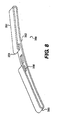
- the progressive spring 400 shown in Figs, 9-10 achieves a spring constant that varies with the compression of the spring by providing curved portions 406 to the elastic element or elements 404.
- the legs of the elastic elements 404 move relative to the base 402 about end points 410, providing a first spring constant.
- additional spring constants result from the bending about points 412, 414, providing the desired progressive spring constant characteristics.
- the ends 408 of the elastic elements 404 are curved towards the base 402, to prevent digging into the retaining clamp.
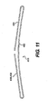
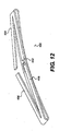
- FIGS 11 and 12 show another exemplary embodiment of the resilient element according to the invention.
- the spring 450 in this embodiment has a base 452 from which extend two elastic elements 454, each including two legs 456, 458.
- the ends of the legs 456, 458 may diverge from the base 452, providing a smaller profile of the spring, and a larger area of application on which acts the retaining clamp.
Landscapes
- Engineering & Computer Science (AREA)
- General Engineering & Computer Science (AREA)
- Mechanical Engineering (AREA)
- Braking Arrangements (AREA)
Applications Claiming Priority (1)
| Application Number | Priority Date | Filing Date | Title |
|---|---|---|---|
| US12/266,924 US8215458B2 (en) | 2008-11-07 | 2008-11-07 | Fixedly connected pad retaining spring for a brake pad |
Publications (2)
| Publication Number | Publication Date |
|---|---|
| EP2184506A1 true EP2184506A1 (fr) | 2010-05-12 |
| EP2184506B1 EP2184506B1 (fr) | 2014-01-08 |
Family
ID=41694643
Family Applications (1)
| Application Number | Title | Priority Date | Filing Date |
|---|---|---|---|
| EP09013936.1A Not-in-force EP2184506B1 (fr) | 2008-11-07 | 2009-11-06 | Plaquette connectée fixe retenant un ressort pour plaquette de frein à disque |
Country Status (2)
| Country | Link |
|---|---|
| US (1) | US8215458B2 (fr) |
| EP (1) | EP2184506B1 (fr) |
Cited By (5)
| Publication number | Priority date | Publication date | Assignee | Title |
|---|---|---|---|---|
| WO2014041157A1 (fr) * | 2012-09-17 | 2014-03-20 | Knorr-Bremse Systeme für Nutzfahrzeuge GmbH | Agencement d'un étrier de support de garniture sur un étrier de frein à disque et garniture de frein |
| WO2014183829A1 (fr) * | 2013-05-13 | 2014-11-20 | Wabco Europe Bvba | Frein à disque à étrier d'un véhicule, en particulier d'un véhicule utilitaire, et ressort de retenue d'un tel frein |
| EP3423731A1 (fr) * | 2016-03-03 | 2019-01-09 | Bendix Spicer Foundation Brake LLC | Frein à disque et ensemble plaquette de frein |
| EP3848604A1 (fr) * | 2020-01-08 | 2021-07-14 | Meritor Heavy Vehicle Braking Systems (UK) Limited | Ressort de plaquette de frein à disque |
| US20220290727A1 (en) * | 2019-09-02 | 2022-09-15 | Volvo Truck Corporation | Brake pad retainer arrangement |
Families Citing this family (14)
| Publication number | Priority date | Publication date | Assignee | Title |
|---|---|---|---|---|
| DE102013008161A1 (de) * | 2013-05-13 | 2014-11-13 | Wabco Europe Bvba | Sattelscheibenbremse eines Fahrzeugs, insbesondere eines Nutzfahrzeuges, und Bremssattel einer solchen Bremse |
| DE102013008155A1 (de) * | 2013-05-13 | 2014-11-13 | Wabco Europe Bvba | Sattelscheibenbremse eines Fahrzeugs, insbesondere eines Nutzfahrzeugs, und Niederhalteeinrichtung einer solchen Bremse |
| JP5753561B2 (ja) * | 2013-09-17 | 2015-07-22 | 日清紡ブレーキ株式会社 | 摩擦材 |
| DE102014019619A1 (de) * | 2014-12-29 | 2016-06-30 | Wabco Europe Bvba | Scheibenbremse, insbesondere für Nutzfahrzeuge |
| KR102249395B1 (ko) * | 2015-01-09 | 2021-05-07 | 현대모비스 주식회사 | 차량용 브레이크의 이물질제거장치 |
| US10036437B2 (en) | 2015-11-12 | 2018-07-31 | Bendix Spicer Foundation Brake Llc | Disc brake and set of brake pads |
| CN109328273B (zh) * | 2016-05-20 | 2020-07-17 | 克诺尔商用车制动系统有限公司 | 用于商用车的盘式制动器、制动衬片以及制动衬片组 |
| DE102016124310A1 (de) * | 2016-12-14 | 2018-06-14 | Knorr-Bremse Systeme für Nutzfahrzeuge GmbH | Scheibenbremse für ein Nutzfahrzeug und Bremsbelagsatz |
| DE102017008809A1 (de) * | 2017-09-20 | 2019-03-21 | Wabco Europe Bvba | Belaghaltesystem für eine Scheibenbremse |
| KR102242177B1 (ko) * | 2018-11-05 | 2021-04-21 | (주)화승코퍼레이션 | 브레이크 장치 |
| KR102210465B1 (ko) * | 2019-09-03 | 2021-01-29 | 현대모비스 주식회사 | 브레이크 장치용 패드라이너 |
| KR102301939B1 (ko) * | 2019-11-08 | 2021-09-17 | 스톨츠 주식회사 | 브레이크 에어덕트 및 이를 포함하는 브레이크 시스템 |
| KR102243281B1 (ko) * | 2019-11-20 | 2021-04-22 | 주식회사 가리언 | 주행가능한 작업차용 공용 브레이크 장치 |
| KR102243542B1 (ko) * | 2019-11-27 | 2021-04-23 | 주식회사 진흥브레이크 | 브레이크 패드용 마찰재 |
Citations (7)
| Publication number | Priority date | Publication date | Assignee | Title |
|---|---|---|---|---|
| DE3027139A1 (de) * | 1979-07-20 | 1981-02-05 | Tokico Ltd | Scheibenbremse |
| DE3124631A1 (de) * | 1981-06-23 | 1983-01-13 | Tokico Ltd., Kawasaki, Kanagawa | Bremsbelagfeder fuer eine teilbelag-scheibenbremse |
| US4784242A (en) * | 1986-10-31 | 1988-11-15 | Bendix France | Pad for a disc brake and disc brake equipped with such pads |
| EP0534987A1 (fr) | 1990-06-26 | 1993-04-07 | Knorr Bremse Ag | Fixation de garnitures de freins a disque pour vehicules routiers, en particulier des vehicules utilitaires. |
| EP0747608A1 (fr) * | 1995-06-05 | 1996-12-11 | Sumitomo Electric Industries, Limited | Frein à disque |
| EP1441141A1 (fr) * | 2003-01-25 | 2004-07-28 | Meritor Heavy Vehicle Braking Systems (UK) Limited | Fixation de garnitures de freins à disque |
| DE102006034764A1 (de) * | 2005-12-14 | 2007-06-28 | Knorr-Bremse Systeme für Nutzfahrzeuge GmbH | Bremsbelag für eine Scheibenbremse |
Family Cites Families (5)
| Publication number | Priority date | Publication date | Assignee | Title |
|---|---|---|---|---|
| US3660081A (en) * | 1970-01-26 | 1972-05-02 | Union Carbide Corp | Method making ferrosilicon alloy |
| US4290508A (en) * | 1978-09-14 | 1981-09-22 | Lucas Industries Limited | Disc brake pad assemblies |
| DE3425670A1 (de) * | 1984-07-12 | 1986-02-06 | Alfred Teves Gmbh, 6000 Frankfurt | Bremsbackenanordnung und verfahren zur herstellung einer bremsbacke |
| DE8507498U1 (de) * | 1985-03-14 | 1986-07-17 | Textar Gmbh, 5090 Leverkusen | Bremsbacke mit Federanordnung |
| GB0322910D0 (en) * | 2003-09-30 | 2003-11-05 | Meritor Heavy Vehicle Braking | Brake caliper and brake pad |
-
2008
- 2008-11-07 US US12/266,924 patent/US8215458B2/en not_active Expired - Fee Related
-
2009
- 2009-11-06 EP EP09013936.1A patent/EP2184506B1/fr not_active Not-in-force
Patent Citations (7)
| Publication number | Priority date | Publication date | Assignee | Title |
|---|---|---|---|---|
| DE3027139A1 (de) * | 1979-07-20 | 1981-02-05 | Tokico Ltd | Scheibenbremse |
| DE3124631A1 (de) * | 1981-06-23 | 1983-01-13 | Tokico Ltd., Kawasaki, Kanagawa | Bremsbelagfeder fuer eine teilbelag-scheibenbremse |
| US4784242A (en) * | 1986-10-31 | 1988-11-15 | Bendix France | Pad for a disc brake and disc brake equipped with such pads |
| EP0534987A1 (fr) | 1990-06-26 | 1993-04-07 | Knorr Bremse Ag | Fixation de garnitures de freins a disque pour vehicules routiers, en particulier des vehicules utilitaires. |
| EP0747608A1 (fr) * | 1995-06-05 | 1996-12-11 | Sumitomo Electric Industries, Limited | Frein à disque |
| EP1441141A1 (fr) * | 2003-01-25 | 2004-07-28 | Meritor Heavy Vehicle Braking Systems (UK) Limited | Fixation de garnitures de freins à disque |
| DE102006034764A1 (de) * | 2005-12-14 | 2007-06-28 | Knorr-Bremse Systeme für Nutzfahrzeuge GmbH | Bremsbelag für eine Scheibenbremse |
Cited By (12)
| Publication number | Priority date | Publication date | Assignee | Title |
|---|---|---|---|---|
| WO2014041157A1 (fr) * | 2012-09-17 | 2014-03-20 | Knorr-Bremse Systeme für Nutzfahrzeuge GmbH | Agencement d'un étrier de support de garniture sur un étrier de frein à disque et garniture de frein |
| US9829056B2 (en) | 2012-09-17 | 2017-11-28 | Knorr-Bremse Systeme Fuer Nutzfahrzeuge Gmbh | Arrangement of a pad retaining clip on the brake caliper of a disc brake, and brake pad |
| RU2647337C2 (ru) * | 2012-09-17 | 2018-03-15 | Кнорр-Бремзе Зюстеме Фюр Нутцфарцойге Гмбх | Компоновка удерживающего тормозные колодки хомута на тормозном суппорте дискового тормозного механизма и тормозная колодка |
| WO2014183829A1 (fr) * | 2013-05-13 | 2014-11-20 | Wabco Europe Bvba | Frein à disque à étrier d'un véhicule, en particulier d'un véhicule utilitaire, et ressort de retenue d'un tel frein |
| US9695894B2 (en) | 2013-05-13 | 2017-07-04 | Wabco Europe Bvba | Caliper disc brake of a vehicle, in particular a commercial vehicle, and holding-down spring of such a brake |
| RU2672508C2 (ru) * | 2013-05-13 | 2018-11-15 | Вабко Юроп Бвба | Дисковый тормоз с суппортом транспортного средства, в частности автомобиля промышленного назначения, и прижимной пружинный элемент такого тормоза |
| EP3423731A1 (fr) * | 2016-03-03 | 2019-01-09 | Bendix Spicer Foundation Brake LLC | Frein à disque et ensemble plaquette de frein |
| EP3423731A4 (fr) * | 2016-03-03 | 2020-05-20 | Bendix Spicer Foundation Brake LLC | Frein à disque et ensemble plaquette de frein |
| US20220290727A1 (en) * | 2019-09-02 | 2022-09-15 | Volvo Truck Corporation | Brake pad retainer arrangement |
| EP3848604A1 (fr) * | 2020-01-08 | 2021-07-14 | Meritor Heavy Vehicle Braking Systems (UK) Limited | Ressort de plaquette de frein à disque |
| US11655866B2 (en) | 2020-01-08 | 2023-05-23 | Meritor Heavy Vehicle Braking Systems (Uk) Limited | Disc brake pad spring |
| EP4212756A1 (fr) * | 2020-01-08 | 2023-07-19 | Meritor Heavy Vehicle Braking Systems (UK) Limited | Ressort de plaquette de frein a disque |
Also Published As
| Publication number | Publication date |
|---|---|
| US20100116600A1 (en) | 2010-05-13 |
| US8215458B2 (en) | 2012-07-10 |
| EP2184506B1 (fr) | 2014-01-08 |
Similar Documents
| Publication | Publication Date | Title |
|---|---|---|
| EP2184506B1 (fr) | Plaquette connectée fixe retenant un ressort pour plaquette de frein à disque | |
| US11078975B2 (en) | Disc brake for a commercial vehicle and brake pad set | |
| US9303704B2 (en) | Mounting system for disk brake pad | |
| JP6326100B2 (ja) | 塑性変形可能な復元ばねを備える自動車のためのディスクブレーキおよび復元ばね | |
| RU2398982C2 (ru) | Фрикционный элемент и дисковый тормоз | |
| AU2016235731B2 (en) | Disc brake pad retention system and mounting method | |
| JP2015526666A5 (fr) | ||
| US20140305754A1 (en) | Spring-Equipped Member for Guiding a Disc Brake Pad and Disc Brake provided with such Guiding Members | |
| CN111480019B (zh) | 用于商用车的盘式制动器和制动衬面组 | |
| CN110382903B (zh) | 用于盘式制动器组件的制动夹和包括这种制动夹的盘式制动器组件 | |
| CN111255787A (zh) | 夹持元件、用于组装夹持元件的方法、用于夹持夹持元件的方法和元件和夹持元件的系统 | |
| US7654372B2 (en) | Shoe-hold apparatus for drum brake device | |
| US11226018B2 (en) | Caliper cover with biasly engaged mounts | |
| US10774889B2 (en) | Brake assembly with brake pad carrier and clip | |
| CN110730876B (zh) | 盘式制动器 | |
| EP3452736B1 (fr) | Ensemble de frein à disque hydraulique et ensemble de plaquette pour celui-ci | |
| CN113748273A (zh) | 用于复位制动垫片的装置和盘式制动器 | |
| CN115929817A (zh) | 用于盘式制动器组件的制动夹和装置 | |
| CN114729672B (zh) | 具有主动缩回元件的坯件优化的制动器滑动夹 | |
| CN220523140U (zh) | 制动装置及车辆 | |
| EP1650459A1 (fr) | Dispositif de maintien des garnitures de frein garnitures de friction d'un frein à disque | |
| CN118119775A (zh) | 用于衬块的复位、衬块的安装和导引的衬块弹簧 | |
| EP0501534A1 (fr) | Ressort anti-bruit pour frein à disque | |
| KR20190064806A (ko) | 패드 플레이트용 클립 | |
| KR20240058380A (ko) | 브레이크 장치 및 차량 |
Legal Events
| Date | Code | Title | Description |
|---|---|---|---|
| PUAI | Public reference made under article 153(3) epc to a published international application that has entered the european phase |
Free format text: ORIGINAL CODE: 0009012 |
|
| AK | Designated contracting states |
Kind code of ref document: A1 Designated state(s): AT BE BG CH CY CZ DE DK EE ES FI FR GB GR HR HU IE IS IT LI LT LU LV MC MK MT NL NO PL PT RO SE SI SK SM TR |
|
| AX | Request for extension of the european patent |
Extension state: AL BA RS |
|
| 17P | Request for examination filed |
Effective date: 20101112 |
|
| 17Q | First examination report despatched |
Effective date: 20110119 |
|
| GRAP | Despatch of communication of intention to grant a patent |
Free format text: ORIGINAL CODE: EPIDOSNIGR1 |
|
| INTG | Intention to grant announced |
Effective date: 20130807 |
|
| RIN1 | Information on inventor provided before grant (corrected) |
Inventor name: WOLF, DENNIS, JR. Inventor name: EBENHOFER, MARTIN |
|
| GRAS | Grant fee paid |
Free format text: ORIGINAL CODE: EPIDOSNIGR3 |
|
| GRAA | (expected) grant |
Free format text: ORIGINAL CODE: 0009210 |
|
| AK | Designated contracting states |
Kind code of ref document: B1 Designated state(s): AT BE BG CH CY CZ DE DK EE ES FI FR GB GR HR HU IE IS IT LI LT LU LV MC MK MT NL NO PL PT RO SE SI SK SM TR |
|
| REG | Reference to a national code |
Ref country code: GB Ref legal event code: FG4D |
|
| REG | Reference to a national code |
Ref country code: CH Ref legal event code: EP |
|
| REG | Reference to a national code |
Ref country code: IE Ref legal event code: FG4D |
|
| REG | Reference to a national code |
Ref country code: AT Ref legal event code: REF Ref document number: 648947 Country of ref document: AT Kind code of ref document: T Effective date: 20140215 |
|
| REG | Reference to a national code |
Ref country code: DE Ref legal event code: R096 Ref document number: 602009021228 Country of ref document: DE Effective date: 20140220 |
|
| REG | Reference to a national code |
Ref country code: AT Ref legal event code: MK05 Ref document number: 648947 Country of ref document: AT Kind code of ref document: T Effective date: 20140108 |
|
| REG | Reference to a national code |
Ref country code: NL Ref legal event code: VDEP Effective date: 20140108 |
|
| REG | Reference to a national code |
Ref country code: LT Ref legal event code: MG4D |
|
| PG25 | Lapsed in a contracting state [announced via postgrant information from national office to epo] |
Ref country code: LT Free format text: LAPSE BECAUSE OF FAILURE TO SUBMIT A TRANSLATION OF THE DESCRIPTION OR TO PAY THE FEE WITHIN THE PRESCRIBED TIME-LIMIT Effective date: 20140108 Ref country code: NO Free format text: LAPSE BECAUSE OF FAILURE TO SUBMIT A TRANSLATION OF THE DESCRIPTION OR TO PAY THE FEE WITHIN THE PRESCRIBED TIME-LIMIT Effective date: 20140408 Ref country code: IS Free format text: LAPSE BECAUSE OF FAILURE TO SUBMIT A TRANSLATION OF THE DESCRIPTION OR TO PAY THE FEE WITHIN THE PRESCRIBED TIME-LIMIT Effective date: 20140508 |
|
| PG25 | Lapsed in a contracting state [announced via postgrant information from national office to epo] |
Ref country code: PT Free format text: LAPSE BECAUSE OF FAILURE TO SUBMIT A TRANSLATION OF THE DESCRIPTION OR TO PAY THE FEE WITHIN THE PRESCRIBED TIME-LIMIT Effective date: 20140508 Ref country code: FI Free format text: LAPSE BECAUSE OF FAILURE TO SUBMIT A TRANSLATION OF THE DESCRIPTION OR TO PAY THE FEE WITHIN THE PRESCRIBED TIME-LIMIT Effective date: 20140108 Ref country code: AT Free format text: LAPSE BECAUSE OF FAILURE TO SUBMIT A TRANSLATION OF THE DESCRIPTION OR TO PAY THE FEE WITHIN THE PRESCRIBED TIME-LIMIT Effective date: 20140108 Ref country code: SE Free format text: LAPSE BECAUSE OF FAILURE TO SUBMIT A TRANSLATION OF THE DESCRIPTION OR TO PAY THE FEE WITHIN THE PRESCRIBED TIME-LIMIT Effective date: 20140108 Ref country code: CY Free format text: LAPSE BECAUSE OF FAILURE TO SUBMIT A TRANSLATION OF THE DESCRIPTION OR TO PAY THE FEE WITHIN THE PRESCRIBED TIME-LIMIT Effective date: 20140108 Ref country code: NL Free format text: LAPSE BECAUSE OF FAILURE TO SUBMIT A TRANSLATION OF THE DESCRIPTION OR TO PAY THE FEE WITHIN THE PRESCRIBED TIME-LIMIT Effective date: 20140108 Ref country code: ES Free format text: LAPSE BECAUSE OF FAILURE TO SUBMIT A TRANSLATION OF THE DESCRIPTION OR TO PAY THE FEE WITHIN THE PRESCRIBED TIME-LIMIT Effective date: 20140108 |
|
| PG25 | Lapsed in a contracting state [announced via postgrant information from national office to epo] |
Ref country code: LV Free format text: LAPSE BECAUSE OF FAILURE TO SUBMIT A TRANSLATION OF THE DESCRIPTION OR TO PAY THE FEE WITHIN THE PRESCRIBED TIME-LIMIT Effective date: 20140108 Ref country code: BE Free format text: LAPSE BECAUSE OF FAILURE TO SUBMIT A TRANSLATION OF THE DESCRIPTION OR TO PAY THE FEE WITHIN THE PRESCRIBED TIME-LIMIT Effective date: 20140108 Ref country code: HR Free format text: LAPSE BECAUSE OF FAILURE TO SUBMIT A TRANSLATION OF THE DESCRIPTION OR TO PAY THE FEE WITHIN THE PRESCRIBED TIME-LIMIT Effective date: 20140108 |
|
| REG | Reference to a national code |
Ref country code: DE Ref legal event code: R026 Ref document number: 602009021228 Country of ref document: DE |
|
| PLBI | Opposition filed |
Free format text: ORIGINAL CODE: 0009260 |
|
| PG25 | Lapsed in a contracting state [announced via postgrant information from national office to epo] |
Ref country code: CZ Free format text: LAPSE BECAUSE OF FAILURE TO SUBMIT A TRANSLATION OF THE DESCRIPTION OR TO PAY THE FEE WITHIN THE PRESCRIBED TIME-LIMIT Effective date: 20140108 Ref country code: RO Free format text: LAPSE BECAUSE OF FAILURE TO SUBMIT A TRANSLATION OF THE DESCRIPTION OR TO PAY THE FEE WITHIN THE PRESCRIBED TIME-LIMIT Effective date: 20140108 Ref country code: EE Free format text: LAPSE BECAUSE OF FAILURE TO SUBMIT A TRANSLATION OF THE DESCRIPTION OR TO PAY THE FEE WITHIN THE PRESCRIBED TIME-LIMIT Effective date: 20140108 Ref country code: DK Free format text: LAPSE BECAUSE OF FAILURE TO SUBMIT A TRANSLATION OF THE DESCRIPTION OR TO PAY THE FEE WITHIN THE PRESCRIBED TIME-LIMIT Effective date: 20140108 |
|
| 26 | Opposition filed |
Opponent name: VRI-VERBAND DER REIBBELAGINDUSTRIE E.V. Effective date: 20141007 |
|
| PLAX | Notice of opposition and request to file observation + time limit sent |
Free format text: ORIGINAL CODE: EPIDOSNOBS2 |
|
| PG25 | Lapsed in a contracting state [announced via postgrant information from national office to epo] |
Ref country code: PL Free format text: LAPSE BECAUSE OF FAILURE TO SUBMIT A TRANSLATION OF THE DESCRIPTION OR TO PAY THE FEE WITHIN THE PRESCRIBED TIME-LIMIT Effective date: 20140108 Ref country code: SK Free format text: LAPSE BECAUSE OF FAILURE TO SUBMIT A TRANSLATION OF THE DESCRIPTION OR TO PAY THE FEE WITHIN THE PRESCRIBED TIME-LIMIT Effective date: 20140108 |
|
| REG | Reference to a national code |
Ref country code: DE Ref legal event code: R026 Ref document number: 602009021228 Country of ref document: DE Effective date: 20141007 |
|
| PLAF | Information modified related to communication of a notice of opposition and request to file observations + time limit |
Free format text: ORIGINAL CODE: EPIDOSCOBS2 |
|
| PLBB | Reply of patent proprietor to notice(s) of opposition received |
Free format text: ORIGINAL CODE: EPIDOSNOBS3 |
|
| PG25 | Lapsed in a contracting state [announced via postgrant information from national office to epo] |
Ref country code: SI Free format text: LAPSE BECAUSE OF FAILURE TO SUBMIT A TRANSLATION OF THE DESCRIPTION OR TO PAY THE FEE WITHIN THE PRESCRIBED TIME-LIMIT Effective date: 20140108 |
|
| PG25 | Lapsed in a contracting state [announced via postgrant information from national office to epo] |
Ref country code: MC Free format text: LAPSE BECAUSE OF FAILURE TO SUBMIT A TRANSLATION OF THE DESCRIPTION OR TO PAY THE FEE WITHIN THE PRESCRIBED TIME-LIMIT Effective date: 20140108 Ref country code: LU Free format text: LAPSE BECAUSE OF FAILURE TO SUBMIT A TRANSLATION OF THE DESCRIPTION OR TO PAY THE FEE WITHIN THE PRESCRIBED TIME-LIMIT Effective date: 20141106 |
|
| REG | Reference to a national code |
Ref country code: CH Ref legal event code: PL |
|
| GBPC | Gb: european patent ceased through non-payment of renewal fee |
Effective date: 20141106 |
|
| PG25 | Lapsed in a contracting state [announced via postgrant information from national office to epo] |
Ref country code: LI Free format text: LAPSE BECAUSE OF NON-PAYMENT OF DUE FEES Effective date: 20141130 Ref country code: CH Free format text: LAPSE BECAUSE OF NON-PAYMENT OF DUE FEES Effective date: 20141130 |
|
| REG | Reference to a national code |
Ref country code: IE Ref legal event code: MM4A |
|
| REG | Reference to a national code |
Ref country code: FR Ref legal event code: ST Effective date: 20150731 |
|
| PG25 | Lapsed in a contracting state [announced via postgrant information from national office to epo] |
Ref country code: GB Free format text: LAPSE BECAUSE OF NON-PAYMENT OF DUE FEES Effective date: 20141106 Ref country code: IE Free format text: LAPSE BECAUSE OF NON-PAYMENT OF DUE FEES Effective date: 20141106 |
|
| PG25 | Lapsed in a contracting state [announced via postgrant information from national office to epo] |
Ref country code: FR Free format text: LAPSE BECAUSE OF NON-PAYMENT OF DUE FEES Effective date: 20141201 |
|
| PG25 | Lapsed in a contracting state [announced via postgrant information from national office to epo] |
Ref country code: SM Free format text: LAPSE BECAUSE OF FAILURE TO SUBMIT A TRANSLATION OF THE DESCRIPTION OR TO PAY THE FEE WITHIN THE PRESCRIBED TIME-LIMIT Effective date: 20140108 |
|
| PG25 | Lapsed in a contracting state [announced via postgrant information from national office to epo] |
Ref country code: GR Free format text: LAPSE BECAUSE OF FAILURE TO SUBMIT A TRANSLATION OF THE DESCRIPTION OR TO PAY THE FEE WITHIN THE PRESCRIBED TIME-LIMIT Effective date: 20140409 Ref country code: IT Free format text: LAPSE BECAUSE OF FAILURE TO SUBMIT A TRANSLATION OF THE DESCRIPTION OR TO PAY THE FEE WITHIN THE PRESCRIBED TIME-LIMIT Effective date: 20140108 Ref country code: BG Free format text: LAPSE BECAUSE OF FAILURE TO SUBMIT A TRANSLATION OF THE DESCRIPTION OR TO PAY THE FEE WITHIN THE PRESCRIBED TIME-LIMIT Effective date: 20140108 |
|
| PG25 | Lapsed in a contracting state [announced via postgrant information from national office to epo] |
Ref country code: MT Free format text: LAPSE BECAUSE OF FAILURE TO SUBMIT A TRANSLATION OF THE DESCRIPTION OR TO PAY THE FEE WITHIN THE PRESCRIBED TIME-LIMIT Effective date: 20140108 Ref country code: HU Free format text: LAPSE BECAUSE OF FAILURE TO SUBMIT A TRANSLATION OF THE DESCRIPTION OR TO PAY THE FEE WITHIN THE PRESCRIBED TIME-LIMIT; INVALID AB INITIO Effective date: 20091106 Ref country code: TR Free format text: LAPSE BECAUSE OF FAILURE TO SUBMIT A TRANSLATION OF THE DESCRIPTION OR TO PAY THE FEE WITHIN THE PRESCRIBED TIME-LIMIT Effective date: 20140108 |
|
| PLAB | Opposition data, opponent's data or that of the opponent's representative modified |
Free format text: ORIGINAL CODE: 0009299OPPO |
|
| R26 | Opposition filed (corrected) |
Opponent name: VRI-VERBAND DER REIBBELAGINDUSTRIE E.V. Effective date: 20141007 |
|
| REG | Reference to a national code |
Ref country code: DE Ref legal event code: R100 Ref document number: 602009021228 Country of ref document: DE |
|
| PLCK | Communication despatched that opposition was rejected |
Free format text: ORIGINAL CODE: EPIDOSNREJ1 |
|
| PLBN | Opposition rejected |
Free format text: ORIGINAL CODE: 0009273 |
|
| STAA | Information on the status of an ep patent application or granted ep patent |
Free format text: STATUS: OPPOSITION REJECTED |
|
| 27O | Opposition rejected |
Effective date: 20161125 |
|
| PG25 | Lapsed in a contracting state [announced via postgrant information from national office to epo] |
Ref country code: MK Free format text: LAPSE BECAUSE OF FAILURE TO SUBMIT A TRANSLATION OF THE DESCRIPTION OR TO PAY THE FEE WITHIN THE PRESCRIBED TIME-LIMIT Effective date: 20140108 |
|
| PGFP | Annual fee paid to national office [announced via postgrant information from national office to epo] |
Ref country code: DE Payment date: 20181122 Year of fee payment: 10 |
|
| REG | Reference to a national code |
Ref country code: DE Ref legal event code: R119 Ref document number: 602009021228 Country of ref document: DE |
|
| PG25 | Lapsed in a contracting state [announced via postgrant information from national office to epo] |
Ref country code: DE Free format text: LAPSE BECAUSE OF NON-PAYMENT OF DUE FEES Effective date: 20200603 |