EP2181651A1 - Instrument et système pour produire un échantillon d'un corps liquide et analyse correspondante - Google Patents
Instrument et système pour produire un échantillon d'un corps liquide et analyse correspondante Download PDFInfo
- Publication number
- EP2181651A1 EP2181651A1 EP08018873A EP08018873A EP2181651A1 EP 2181651 A1 EP2181651 A1 EP 2181651A1 EP 08018873 A EP08018873 A EP 08018873A EP 08018873 A EP08018873 A EP 08018873A EP 2181651 A1 EP2181651 A1 EP 2181651A1
- Authority
- EP
- European Patent Office
- Prior art keywords
- skin
- lancing
- instrument
- pressure ring
- analysis
- Prior art date
- Legal status (The legal status is an assumption and is not a legal conclusion. Google has not performed a legal analysis and makes no representation as to the accuracy of the status listed.)
- Withdrawn
Links
Images


Classifications
-
- A—HUMAN NECESSITIES
- A61—MEDICAL OR VETERINARY SCIENCE; HYGIENE
- A61B—DIAGNOSIS; SURGERY; IDENTIFICATION
- A61B5/00—Measuring for diagnostic purposes; Identification of persons
- A61B5/15—Devices for taking samples of blood
- A61B5/151—Devices specially adapted for taking samples of capillary blood, e.g. by lancets, needles or blades
- A61B5/15186—Devices loaded with a single lancet, i.e. a single lancet with or without a casing is loaded into a reusable drive device and then discarded after use; drive devices reloadable for multiple use
- A61B5/15188—Constructional features of reusable driving devices
- A61B5/15192—Constructional features of reusable driving devices comprising driving means, e.g. a spring, for retracting the lancet unit into the driving device housing
- A61B5/15194—Constructional features of reusable driving devices comprising driving means, e.g. a spring, for retracting the lancet unit into the driving device housing fully automatically retracted, i.e. the retraction does not require a deliberate action by the user, e.g. by terminating the contact with the patient's skin
-
- A—HUMAN NECESSITIES
- A61—MEDICAL OR VETERINARY SCIENCE; HYGIENE
- A61B—DIAGNOSIS; SURGERY; IDENTIFICATION
- A61B5/00—Measuring for diagnostic purposes; Identification of persons
- A61B5/14—Devices for taking samples of blood ; Measuring characteristics of blood in vivo, e.g. gas concentration within the blood, pH-value of blood
- A61B5/1405—Devices for taking blood samples
- A61B5/1427—Multiple blood sampling, e.g. at periodic or pre-established intervals
-
- A—HUMAN NECESSITIES
- A61—MEDICAL OR VETERINARY SCIENCE; HYGIENE
- A61B—DIAGNOSIS; SURGERY; IDENTIFICATION
- A61B5/00—Measuring for diagnostic purposes; Identification of persons
- A61B5/145—Measuring characteristics of blood in vivo, e.g. gas concentration, pH value; Measuring characteristics of body fluids or tissues, e.g. interstitial fluid, cerebral tissue
- A61B5/14532—Measuring characteristics of blood in vivo, e.g. gas concentration, pH value; Measuring characteristics of body fluids or tissues, e.g. interstitial fluid, cerebral tissue for measuring glucose, e.g. by tissue impedance measurement
-
- A—HUMAN NECESSITIES
- A61—MEDICAL OR VETERINARY SCIENCE; HYGIENE
- A61B—DIAGNOSIS; SURGERY; IDENTIFICATION
- A61B5/00—Measuring for diagnostic purposes; Identification of persons
- A61B5/15—Devices for taking samples of blood
- A61B5/150007—Details
- A61B5/150015—Source of blood
- A61B5/150022—Source of blood for capillary blood or interstitial fluid
-
- A—HUMAN NECESSITIES
- A61—MEDICAL OR VETERINARY SCIENCE; HYGIENE
- A61B—DIAGNOSIS; SURGERY; IDENTIFICATION
- A61B5/00—Measuring for diagnostic purposes; Identification of persons
- A61B5/15—Devices for taking samples of blood
- A61B5/150007—Details
- A61B5/150053—Details for enhanced collection of blood or interstitial fluid at the sample site, e.g. by applying compression, heat, vibration, ultrasound, suction or vacuum to tissue; for reduction of pain or discomfort; Skin piercing elements, e.g. blades, needles, lancets or canulas, with adjustable piercing speed
- A61B5/150061—Means for enhancing collection
- A61B5/150068—Means for enhancing collection by tissue compression, e.g. with specially designed surface of device contacting the skin area to be pierced
-
- A—HUMAN NECESSITIES
- A61—MEDICAL OR VETERINARY SCIENCE; HYGIENE
- A61B—DIAGNOSIS; SURGERY; IDENTIFICATION
- A61B5/00—Measuring for diagnostic purposes; Identification of persons
- A61B5/15—Devices for taking samples of blood
- A61B5/150007—Details
- A61B5/150175—Adjustment of penetration depth
- A61B5/150183—Depth adjustment mechanism using end caps mounted at the distal end of the sampling device, i.e. the end-caps are adjustably positioned relative to the piercing device housing for example by rotating or screwing
-
- A—HUMAN NECESSITIES
- A61—MEDICAL OR VETERINARY SCIENCE; HYGIENE
- A61B—DIAGNOSIS; SURGERY; IDENTIFICATION
- A61B5/00—Measuring for diagnostic purposes; Identification of persons
- A61B5/15—Devices for taking samples of blood
- A61B5/150007—Details
- A61B5/150358—Strips for collecting blood, e.g. absorbent
-
- A—HUMAN NECESSITIES
- A61—MEDICAL OR VETERINARY SCIENCE; HYGIENE
- A61B—DIAGNOSIS; SURGERY; IDENTIFICATION
- A61B5/00—Measuring for diagnostic purposes; Identification of persons
- A61B5/15—Devices for taking samples of blood
- A61B5/150007—Details
- A61B5/150374—Details of piercing elements or protective means for preventing accidental injuries by such piercing elements
- A61B5/150381—Design of piercing elements
- A61B5/150412—Pointed piercing elements, e.g. needles, lancets for piercing the skin
- A61B5/150419—Pointed piercing elements, e.g. needles, lancets for piercing the skin comprising means for capillary action
-
- A—HUMAN NECESSITIES
- A61—MEDICAL OR VETERINARY SCIENCE; HYGIENE
- A61B—DIAGNOSIS; SURGERY; IDENTIFICATION
- A61B5/00—Measuring for diagnostic purposes; Identification of persons
- A61B5/15—Devices for taking samples of blood
- A61B5/150007—Details
- A61B5/150374—Details of piercing elements or protective means for preventing accidental injuries by such piercing elements
- A61B5/150381—Design of piercing elements
- A61B5/150503—Single-ended needles
- A61B5/150511—Details of construction of shaft
-
- A—HUMAN NECESSITIES
- A61—MEDICAL OR VETERINARY SCIENCE; HYGIENE
- A61B—DIAGNOSIS; SURGERY; IDENTIFICATION
- A61B5/00—Measuring for diagnostic purposes; Identification of persons
- A61B5/15—Devices for taking samples of blood
- A61B5/151—Devices specially adapted for taking samples of capillary blood, e.g. by lancets, needles or blades
- A61B5/15101—Details
- A61B5/15103—Piercing procedure
- A61B5/15107—Piercing being assisted by a triggering mechanism
- A61B5/15113—Manually triggered, i.e. the triggering requires a deliberate action by the user such as pressing a drive button
-
- A—HUMAN NECESSITIES
- A61—MEDICAL OR VETERINARY SCIENCE; HYGIENE
- A61B—DIAGNOSIS; SURGERY; IDENTIFICATION
- A61B5/00—Measuring for diagnostic purposes; Identification of persons
- A61B5/15—Devices for taking samples of blood
- A61B5/151—Devices specially adapted for taking samples of capillary blood, e.g. by lancets, needles or blades
- A61B5/15101—Details
- A61B5/15115—Driving means for propelling the piercing element to pierce the skin, e.g. comprising mechanisms based on shape memory alloys, magnetism, solenoids, piezoelectric effect, biased elements, resilient elements, vacuum or compressed fluids
- A61B5/15117—Driving means for propelling the piercing element to pierce the skin, e.g. comprising mechanisms based on shape memory alloys, magnetism, solenoids, piezoelectric effect, biased elements, resilient elements, vacuum or compressed fluids comprising biased elements, resilient elements or a spring, e.g. a helical spring, leaf spring, or elastic strap
-
- A—HUMAN NECESSITIES
- A61—MEDICAL OR VETERINARY SCIENCE; HYGIENE
- A61B—DIAGNOSIS; SURGERY; IDENTIFICATION
- A61B5/00—Measuring for diagnostic purposes; Identification of persons
- A61B5/15—Devices for taking samples of blood
- A61B5/151—Devices specially adapted for taking samples of capillary blood, e.g. by lancets, needles or blades
- A61B5/15101—Details
- A61B5/15126—Means for controlling the lancing movement, e.g. 2D- or 3D-shaped elements, tooth-shaped elements or sliding guides
- A61B5/15128—Means for controlling the lancing movement, e.g. 2D- or 3D-shaped elements, tooth-shaped elements or sliding guides comprising 2D- or 3D-shaped elements, e.g. cams, curved guide rails or threads
-
- A—HUMAN NECESSITIES
- A61—MEDICAL OR VETERINARY SCIENCE; HYGIENE
- A61B—DIAGNOSIS; SURGERY; IDENTIFICATION
- A61B5/00—Measuring for diagnostic purposes; Identification of persons
- A61B5/15—Devices for taking samples of blood
- A61B5/151—Devices specially adapted for taking samples of capillary blood, e.g. by lancets, needles or blades
- A61B5/15186—Devices loaded with a single lancet, i.e. a single lancet with or without a casing is loaded into a reusable drive device and then discarded after use; drive devices reloadable for multiple use
- A61B5/15188—Constructional features of reusable driving devices
- A61B5/1519—Constructional features of reusable driving devices comprising driving means, e.g. a spring, for propelling the piercing unit
-
- A—HUMAN NECESSITIES
- A61—MEDICAL OR VETERINARY SCIENCE; HYGIENE
- A61B—DIAGNOSIS; SURGERY; IDENTIFICATION
- A61B5/00—Measuring for diagnostic purposes; Identification of persons
- A61B5/15—Devices for taking samples of blood
- A61B5/157—Devices characterised by integrated means for measuring characteristics of blood
-
- A—HUMAN NECESSITIES
- A61—MEDICAL OR VETERINARY SCIENCE; HYGIENE
- A61B—DIAGNOSIS; SURGERY; IDENTIFICATION
- A61B5/00—Measuring for diagnostic purposes; Identification of persons
- A61B5/15—Devices for taking samples of blood
- A61B5/151—Devices specially adapted for taking samples of capillary blood, e.g. by lancets, needles or blades
- A61B5/15101—Details
- A61B5/15115—Driving means for propelling the piercing element to pierce the skin, e.g. comprising mechanisms based on shape memory alloys, magnetism, solenoids, piezoelectric effect, biased elements, resilient elements, vacuum or compressed fluids
- A61B5/15125—Driving means for propelling the piercing element to pierce the skin, e.g. comprising mechanisms based on shape memory alloys, magnetism, solenoids, piezoelectric effect, biased elements, resilient elements, vacuum or compressed fluids comprising a vacuum or compressed fluids
Definitions
- the invention relates to the collection of samples of body liquid for allowing analysis thereof, i.e. determination of an analyte concentration therein.
- it relates to instruments and systems for producing a small sample of body liquid by piercing the skin of a subject (human or animal) using a disposable lancing element having a skin piercing tip suitable for generating a small wound from which the sample is drawn.
- the body liquid is blood or interstitial liquid or a mixture thereof.
- Lancing of the skin is generally performed by a lancing system comprising, as mutually adapted components of the system, a reusable hand-held instrument and lancing elements.
- the movement required for lancing is driven by a lancing drive provided inside a housing of the instrument and adapted for driving a lancing element connected thereto.
- Lancets can be interchangeably connected to the drive and generally are disposible items.
- the lancet After triggering the puncturing movement the lancet is driven in a puncture direction until it reaches a point of maximum displacement and thereafter it is further driven in a reverse direction.
- Many suitable lancet drive mechanisms have been described. In most cases the driving force is supplied by a tensioned spring and the lancet drive further includes suitable mechanical means for converting the force of the spring into the required movement of a lancet.
- the skin contact opening has a relatively large diameter whereby the skin bulges into the skin contact opening forming a target site bulge which penetrates to some extent into the opening when the lancing instrument is pressed with its distal end (i.e. with the skin contact surface) against the skin.
- This bulging action (hereafter designated "target site bulging") is generally combined with additional means for improving sample liquid production, such as a mechanical squeezing acting radially inwardly, a pumping action involving axial movement of parts of the instrument, etc.
- a first aspect of the invention proposes an instrument and a system for producing a sample of body liquid by piercing the skin comprising
- the pressure ring is circular and in this case it should have the specified inner (free) diameter.
- the area of the opening should correspond (i.e. be the same) as the area of a circle with the mentioned diameter values.
- the invention does not rely on target site bulging for automatic expression of a sufficient amount of sample liquid. Rather the inventors have found that it is possible to achieve the required high reliability of sample generation with a combination of a relatively small skin contact opening and a relatively high pressure force which is guaranteed by a pressing force control device. This was unexpected, in particular because it had been assumed that such a high pressure would "press away" the blood, unless the device has a large opening allowing substantial bulging of the skin. This assumption was based - inter alia - on the experience known even to a layperson that pressing with a thin item onto the skin causes a color change from red to white indicating a loss of blood from the respective site.
- the invention overcomes a problem related to target site bulging namely the lack of reproducibility of the penetration depth by which the tip of the lancing element penetrates into the skin.
- z-position position in the direction of the lancing movement
- the penetration depth depends on the exact z-position of the skin surface during the puncturing movement. Due to the bulging this skin position is substantially undefined.
- some prior art devices have means for detection of the exact z-position of the skin by a skin position detection device integrated into the lancing instrument.
- Others operate with a penetration depth reference element having a reference skin contact surface which is contacted to the skin (additionally to the skin contact surface surrounding the skin contact opening of the instrument), for providing a reliable z-position reference during penetration of the lancing element tip into the skin. While these approaches help to achieve a reproducible penetration depth they require a substantial expense in the instrument design and production, making the system less handy and more costly.
- the invention allows an excellent reproducibility of the z-position of the skin at the lancing site and thus an excellent reproducibility of the penetration depth. Simultaneously automatic sample generation (without "milking") is achieved with a simple and inexpensive design of the lancing system.
- a defined pressing force is ensured by a suitable pressing force control device.
- a suitable pressing force control device can be mechanical, in particular comprising a spring device which is arranged in such a manner that its spring force acts between the pressure ring and the housing.
- the spring device is preferably embodied as a metal spring.
- Other spring-like devices are, however, known and can be used, such as a pneumatic spring or a resilient element of an elastic material.
- the term "spring” is used as an example of any such spring device. Preferably it is pre-tensioned, as will be described in more detail below.
- Pressing force control devices operating by electrical means may comprise an electromagnetic drive including a coil and a magnetic core, in particular a voice coil drive.
- the control of the pressure can be fully automatic or it can require an activity of the user.
- electrical means can be used to measure the force by which the pressure ring is pressed against the skin and this force can be indicated to the user by suitable visible, acoustic or tactile means, whereby the user can adapt the pressing force to the desired value.
- the invention proposes a system and an instrument for producing a sample of body liquid by piercing the skin using a lancing element having a skin piercing tip, said instrument having
- the pressure ring protrudes from the peripheral surface by at least 0.5 mm, preferably at least 0.8 mm and not more than 2.0 mm, preferably not more than 1.5 mm.
- the term "pressure ring” is used herein in an essentially geometrical sense, namely referring to a narrow ring-shaped area surrounding the skin contact opening. Forces acting between the instrument and the skin are borne essentially only, or at least preferentially, via the pressure ring.
- the pressure ring is a narrow ring shaped surface area surrounding the skin contact opening and bearing during practical use of the instrument at least 50 %, preferably at least 70 % and most preferably at least 90 % of the forces acting between the instrument and the skin. Consequently according to this aspect of the invention at least the mentioned percentages of the total force acting between the skin and the instrument is borne only by a small ring shaped area of the described maximum dimensions.
- the ring shaped area forming the pressure ring may be part of an annular element with circular cross-section, oftentimes designated as "ring".
- the pressure ring of the invention is embodied as part of a pressure piece, as will be explained further with reference to the drawings.
- the invention proposes a system and an instrument for producing a sample of body liquid by piercing the skin using a lancing element having a skin piercing tip, said instrument having
- the second and the third main aspect of the invention are favorable for any size of skin contact opening and for any pressing force. Particular good results are, however, achieved if the instrument comprises a pressing force control device for controlling the pressing force within the limits specified above with respect to the first main aspect of the invention.
- the skin contact opening should preferably have an opening area corresponding to a circle with a diameter of at least 1.5 mm, preferably at least 2 mm, most preferably at least 2.5 mm and not more than 8 mm, preferably not more than 5 mm and most preferably not more than 3.5 mm.
- the instrument is preferably adapted for operation with an integral lancing and analysis element, both forming a "single unit system" as specified above.
- the lancet of the integral lancing and analysis element is embodied as a direct sampler having a capillary channel for transporting sample liquid produced by piercing the skin by means of capillary flow to a sample collection zone thereof.
- a minimum interaction time period required for lancing and sampling a sufficient amount of sample liquid for analysis is at most 3 seconds.
- the minimum interaction time period is no more than 2 seconds and more preferably it is no more than 1 second.
- This relates specifically to integrated lancing and analysis systems of both types A and B identified above.
- the user interacts with the system by establishing a pressing force between the skin and the pressure ring of the instrument. This can conveniently be done by pressing a hand-held instrument against the finger or other body part. Alternatively the finger or other body part can be pressed against an instrument, lying e.g. on a table.
- timing has generally been only a concern with respect to the "test time", i.e. the total time required for the analysis (from lancing until the analyte concentration is indicated).
- the inventors have found that - deviating from earlier understanding - the duration of the minimum interaction time period ("MITP") is highly critical for achieving the partially contradictory requirements mentioned above.
- This time period is defined as the minimum time duration for which user-instrument interaction (as specified above) is required for lancing and for collecting a sufficient amount of sample for the analysis in a sample collection device of the system.
- the functions performed during the MITP include lancing, expression of sample liquid from the tissue (preferably directly into a capillary of the lancing element) and collecting a sufficient amount of sample.
- the MITP is a system-related quantity which is user-independent, i.e. only determined by the design of the instrument, and possibly by other components of the system. It must not be confused with the actual time of interaction which in each case depends on numerous aspects including the habits of the user. The actual interaction time generally varies between users and, even for a specific user, from analysis to analysis.
- the invention teaches to design the system in such a manner, that the minimum time for which at least every user must interact with the instrument, is below the indicated very small threshold values.
- the starting point of the MITP is a point in time at which the system is "ready for lancing", i.e. the lancing drive is ready for driving a lancing movement of a lancing element connected thereto and the desired lancing site of the skin is property located at the skin contact opening of the instrument.
- a short period of time may be required between establishing the status "ready for lancing” and the triggering of the puncturing movement.
- Such a short (preparatory) delay period may be required by the instrument, for example for detecting the skin position.
- the design is such that no such preparatory time period is needed due to instrumental requirements, i.e. the triggering can immediately take place when the status of the system is "ready for lancing". In this case the starting point of the MITP may coincide with the triggering of the puncturing movement.
- a very short and well defined preparatory delay period may, however, be provided for non-instrumental reasons, in particular to take into account visco-elastic deformation of the skin which takes place after establishing a pressure force between the skin and the pressure ring.
- sample collection device is any part of the system, inside the instrument, in which sample liquid produced as a result of skin lancing is available for analysis. It can, for example, be a chamber or capillary and can be empty, or filled with bibulous material.
- the value of the pressing force during the entire MITP is important. It should preferably be maintained by means of the pressing force control device to be at least 3 N, preferably at least 4 N and more preferably at least 5 N during the MITP. According to another preferred embodiment maximum values should be maintained during the same period, namely at most 10 N, preferably at most 8 N and more preferably at most 7 N.
- the pressing force should be allowed to float in that range during the MITP. Rather it has been found that the maximum variation range of the pressing force should be limited to no more than 15 %, preferably no more than 10 % and more preferably to no more than 5 %. Expressed in absolute values the maximum variation range of the pressing force between the pressure ring and the skin during the MITP should be no more than +/- 0.5 N, preferably not more than +/- 0.3 N and more preferably not more than +/- 0.2 N.
- the MITP is a user-independent quantity which depends only on the design of the system.
- the instrument comprises a MITP controlling device.
- This term refers to any device which helps to make sure that the required interaction between the user and the instrument (i.e. mainly the required pressing force between the skin and the pressure ring) is maintained by the user at least during the MITP.
- the MITP controlling device provides assistance to make sure that the actual interaction between the user and the instrument overlaps (or at least coincides with) the MITP.
- the MITP controlling device need not operate fully automatically in the sense that no acts of the user, such as manual triggering of the puncturing movement, are required. Rather it may provide assistance to the user, in particular by signaling to the user directly or indirectly the start and the end of the MITP.
- the MITP controlling device comprises means for detecting the starting point of the MITP, by detecting the pressing force acting between a pressure ring and the skin using any suitable means (to be discussed in more detail below).
- the pressure corresponds to a predetermined minimum value or range this status can be indicated to the user by a suitable visible, audible or tactile signal.
- the lancing movement can be triggered automatically when the status "ready for lancing" has been detected. In this case there may be no delay between "ready to lance” and triggering, i.e. the MITP starts with the automatic triggering.
- there may be an instrument-controlled delay time e. g. to take into account the time needed for visco-elastic skin-deformation.
- the preparatory delay period between "ready to lance" and triggering is preferably at most 1 sec, more preferably at most 0.7 sec and most preferably at most 0.5 sec.
- a preferred lower limit is 0.2 sec, at least 0.3 sec being more preferred and at least 0.4 sec being most preferred.
- the end of the MITP period is generally indicated to the user by a suitable visible, audible or tactile signal.
- a dedicated MITP controlling device is not necessary for the invention in its most general sense. Depending on the particular situation it may be sufficient for the user to be provided with an indirect indication of the start and end of the MITP. For example the "ready to lance"-status can be “felt” by the user when pressing his finger on a spring-supported pressure ring (to be described in more detail below) and the duration of the MITP may be so short, that it may by sufficient to rely on the "feeling" of the user with respect to the end of the MITP.
- the instrument may have some kind of fill control (as part of the MITP controlling device) indicating a sufficient amount of sample liquid or allowing an analysis only if a sufficient amount of sample has been collected.
- some kind of fill control (as part of the MITP controlling device) indicating a sufficient amount of sample liquid or allowing an analysis only if a sufficient amount of sample has been collected.
- fill control is not required. Rather the end of the MITP is calculated by the instrument using a fixed MITP value (depending on the design of the system components).
- the invention allows to use a simple and inexpensive design of penetration depth adjustment device. For example in order to adapt for small remaining variations of the skin position it may be sufficient to provide interchangeable distance elements or pressure rings to allow a single adaption of the systems to the needs of a particular user.
- the instrument and system of the invention take into account the viscoelastic properties of the skin in an optimized manner. In this way not only a sufficient supply of sample liquid is ensured but also "flooding" by too much sample liquid is avoided.
- the invention allows reliable analysis preferably with very small sample volumes in the order not more than 300 nl, preferably not more than 200 ni, and most preferably not more than 100 nl.
- Figure 1 shows a view of a pressure ring 1 against which a finger tip 2 is pressed with force F.
- the skin 3 bulges into the skin contact opening 4 defined by pressure ring 1.
- the degree of this bulging i.e. the distance between the plane A of pressure ring 1 and the apex of target site bulge 6 depends on the pressing force F, the dimensions of the skin contact opening 4 and the elastic properties of the skin which vary from person to person but also show intra-individual variation for consecutive uses by the same person.
- Figure 1 also shows symbolically the point P of maximum displacement which a piercing tip 7 reaches on its movement path during the puncturing movement.
- the z-positions of the plane of the pressure ring 1 and of the point of maximum displacement P relative to each other i.e. projecting distance s shown in Figure 1
- Figure 1 shows that for a given value of projecting distances s the actual penetration depth depends directly on the degree of target site bulging.
- the diameter D of the skin contact opening 4 is rather small. In this case there is only minimal target site bulging, whereby the reproducibility of the penetration depth of consecutive lancing events is excellent.
- Generation of a sufficient amount of sample liquid is supported by using a narrow pressure ring having a width b of not more than 1.5 mm.
- the pressure ring 1 is a part of a pressure piece 42 which comprises a peripheral surface portion 50 surrounding the pressure ring 1 and recessed from the pressure ring 1.
- the pressure ring 1 protrudes by a protruding distance h from the peripheral surface portion 50.
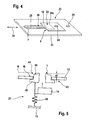
- Figures 2 to 5 show a suitable lancing system 10. It includes a reusable hand-held instrument 11 and a disposable lancing element 12 with a piercing tip 7.
- a housing 13 of the instrument contains a lancing drive 14 and a measurement and evaluation electronics 15 shown only symbolically as a block in Figure 3 .
- a display 16 is provided in order to allow visual indication of information (including status information concerning the system, advice concerning its handling, analytical results etc.) to the user.
- the instrument also comprises a MITP controlling device 17, a device 18 for generating audible signals (such as a buzzer) and/or a device 19 for generating tactile signals (such as a vibration generator).
- lancing element 12 is combined with an analysis element 21, thereby forming an integral lancing and analysis element 22.
- the lancing element 12 is movable, relative to the analysis element 21, in a longitudinal direction symbolized by double arrow 34.
- An analysis element holder 20 is provided for holding the analysis element 22 inside the instrument 11.
- analysis element holder 20 comprises a coupling recess 25 in analysis element 21 and a corresponding coupling protrusion 27 of the instrument.
- the lancing element 12 has a coupling recess 24 cooperating with a coupling protrusion 26 of the instrument.
- the lancet drive 14 shown in Figure 3 comprises a drive rotor 29 with a cam 30 formed by a groove.
- Cam 30 and a corresponding cam traveler 31 form a cam drive mechanism which controls a pivoting movement of a drive rod 32 about a pivoting axis 33.
- drive rotor 29 After triggering of a puncture movement (by triggering means not shown) drive rotor 29 turns with high speed (driven by a drive spring also not shown) about its axis 35 and this rotational movement is translated by means of the cam curve formed by groove 30 and traveled by cam traveler 31 into a corresponding pivoting movement of drive rot 32 which again drives a corresponding up and down movement of lancing element 12 to which it is connected by its coupling protrusion 26 penetrating into coupling recess 24. Similar rotor drives for lancing instruments have been described elsewhere, Thus no more detailed description is necessary.
- the lancing element 12 is a "direct sampler" having a capillary channel 28 inside its piercing tip 7 and leading up to a sample collection zone 23 of lancing element 12.
- capillary channel 28 widens to form a sample reservoir chamber 28a.
- lancing element 12 performs a puncturing movement by which piercing tip 7 is driven into skin 3. Thereafter, preferably during a retraction phase of the puncturing movement, after the piercing tip 7 has reached its point of maximum displacement (but with the piercing tip still being below the surface of skin 3) sample liquid penetrates - driven by capillary forces - into capillary 28 and reservoir chamber 28a.
- capillary 28 and reservoir chamber 28a together form a sample collection device 36 suitable for storing sample liquid, ready for subsequent transfer to an analysis zone 8 of analysis element 21.
- the volume of sample liquid required for the analysis is determined by the liquid volume taken up by the device, in this case by the combined volume of capillary 28 and reservoir chamber 28a.
- sample liquid may be transferred to the adjacent analysis zone 8 of analysis element 21 by means of a suitable fluid communication device.
- a suitable fluid communication device Preferably the arrangement is such that in a first configuration no fluid communication between the sample collection zone of lancing element 12 and the analysis element 21 is provided whereas in a second configuration fluid communication takes place.
- the switching between both configurations can be accomplished by any suitable means, e.g. by pressing zone 23 of lancing element 12 and analysis element 21 together. A more detailed description of such preferred design of an integrated lancing and analysis element with switchable sample transfer is not necessary because it has been described elsewhere.
- the invention can also be used with integral lancing and analysis elements having a lancing part and a analysis part fixed to each other.
- no separate holding devices for the two parts are required. Rather only one holding device is provided which simultaneously serves as lancing element holding device and as analysis element holding device.
- a special feature of the system of the invention relates to a pressing force control device 37 provided in the instrument 11.
- the pressing force control device 37 comprises a spring 38 which is embodied and arranged in such a manner that one end thereof acts against pressure ring 1 and the other end acts against the housing 13. "Acting" in this context does not require immediate contact. Rather it means that the spring exerts a force on the pressure ring and that the corresponding counter-force is (directly or indirectly) borne by the housing.
- one end of spring 38 rests on a wall of housing 13 and its other end presses against a frame element 39 carrying lancing drive 14.
- the force of spring 38 is further transmitted from the frame element 39 to pressure ring 1 via pillar elements 40.
- Pressure ring 1 is embodied as part of a pressure piece 42 which is borne by a pressure ring bearing 43 of housing 13 such that it is axially movable against the force of spring 38.
- spring 38 acts between housing 13 and pressure piece 42 with pressure ring 1.
- drive 14 is connected in a defined spatial configuration with pressure ring 1, in such a manner that the distance between the point of maximum displacement of the lancet movement and the pressure ring 1 is independent from the compression status of the spring 38 and the corresponding axial movement of pressure piece 42.
- the spatial configuration and hence the distance of the pressure ring from the point of maximum displacement can be varied (between puncturing movements) to set the lancing penetration depth. It is, however, fixed during the interaction of the user with the device, i.e. from the point of time at which the pressure ring is first pressed down until the body part is removed therefrom.
- spring 38 is preferably embodied and arranged in such a manner that it is pre-tensioned. This means that the spring is already compressed (or in the case of an extension spring extended) even if no pressing force is exerted onto pressure ring 1, i.e, pressure ring 1 is in its "home” position resting on the surrounding wall (bearing 43) of housing 13.
- the degree of this pre-tensioning is such that the force of spring 38 acting on the pressure ring 1 varies by no more than 20 %, preferably no more than 10 % within the spring-loaded movement range of the pressure ring 1.
- the pressing force control device is adapted to control not only a minimum pressing force but also a maximum pressing force. This is generally favorable but not mandatory.
- the maximum pressing force at the time of triggering is not more than 8 N, preferably not more than 7 N.
- a pressure ring movement limiting arrangement 44 ( figure 5 ) is provided by which the maximum displacement of the pressure ring 1 possible by pressing with a finger 2 or other body part is limited within a fully spring-loaded movement range of the pressure ring.
- this is achieved by a contact surface 46 which is arranged in the vicinity (at the radially outer side) of the pressure ring 1 in such a manner that a body part pressed against the pressure ring 1, and thereby moving the pressure ring, abuts against the contact surface 46. Due to this abutting, the pressure ring can not be moved further, i.e. the possible displacement of the pressure ring (by the body part pressing thereagainst) is limited. With such an embodiment the maximum displacement depends on the distance dr by which the pressure ring protrudes from the instrument housing (contact surface 46). When pressure piece 42 with pressure ring 1 is pressed downwardly this movement is discontinued when finger tip 2 contacts the surface of housing 13 in the vicinity of the pressure ring 1.
- the design is such that the maximum displacement of the pressure ring 1 during practical use is small.
- it should be less than 3 mm, more preferably less than 2 mm and even more preferably less than 1 mm. Therefore the distance dr of the plane A of pressure ring 1 and the adjacent housing surface should not be too large.
- Preferred maximum values can be calculated by adding 0.5 mm to the mentioned maximum displacement values.
- dr should not be too small, among others because it is favorable for the handling of the instrument if a protrusion of pressure ring 1 versus the adjacent housing area simplifies the finding of a suitable finger position for the user. Therefore this protrusion, i.e. the distance dr, should be at least 0.2 mm, and preferably at least 0.5 mm.
- the construction part at which the pressure ring is provided can have many different shapes and designs. In contrast to some earlier devices it should be non-deformable in the sense that it should not be visibly deformed during normal use of the system.
- the term "pressure ring” refers to the ring-shaped surface of the respective part which in practical use, i.e. under the conditions prevailing in using of the particular instrument) bears the major part of the pressing force acting between the instrument and the skin.
- this ring-shaped contact surface i.e. the pressure ring
- a suitable exact shape and width of the pressure ring can be determined experimentally on the basis of the information contained herein.
- the ring should protrude from any adjacent housing surface by a sufficient distance to allow easy tactile recognition thereof by the user.
- pressure ring does not have to be understood as being limited to an uninterrupted ring. Rather the ring shaped surface contacting the skin can have interruptions (for example by recesses) which should, however, be small enough not to spoil the described function of the pressure ring.
- the instrument furthermore comprises a pressure-ring-movement detection device 45.
- a pressure-ring-movement detection device 45 In the context of the second main aspect of the invention it is preferably a part of a MITP control device.
- Means for movement detection are well known, for example a light barrier 46 as shown symbolically in the drawing.
- Such a device detects the movement of pressure piece 42, and hence of pressure ring 1, upon pressing down from its "home" position by finger 2.
- Such detection allows several favorable functions including an indication to the user (via display 16 or generators of audible or tactile signals 18 and 19) that the instrument is "ready for lancing".
- the signal of the pressure-ring-movement detection device can be used for automatically triggering the lancing movement, possibly after a delay time as described above.
- Figure 3 furthermore shows an analysis measurement device 47 as part of the instrument 11.
- This can be any device which is suitable to measure a value of a measurement quantity relating to a change of analysis element 21, which change is a measure of the desired analytical value.
- the analysis measurement device is embodied for a photometric measurement of a detection area in the analysis zone 8 of analysis element 21 including a light source 48, a light detector 49 and corresponding light guide means symbolized by a lens 50.
- Other types of analysis measurement devices could be used as well, in particular electrical measurement devices, as are common for the evaluation of electrochemical analysis elements.
- a MITP control device 17 in accordance with the second main aspect of the invention makes use of the pressure-ring-movement detection device 45.
- MITP control device 17 signals the start of an MITP it generates a signal by at least one of signal generators 18 and 19 and/or automatically triggers a puncturing movement of lancet drive 14.
- the end of the MITP period is determined by the measurement and evaluation electronics 15, for example on the basis of a predefined time period required for generation and transfer of sufficient amount of sample liquid from the finger tip 2.
- suitable sample transfer detection means as are known in the art, e.g.
- the application force control device makes sure that during the entire MITP the pressing force is within the range given by the above identified limiting values.
- the variation of the pressing force during the MITP should be within the above identified variation limitations which are much smaller.
Priority Applications (19)
| Application Number | Priority Date | Filing Date | Title |
|---|---|---|---|
| EP08018873A EP2181651A1 (fr) | 2008-10-29 | 2008-10-29 | Instrument et système pour produire un échantillon d'un corps liquide et analyse correspondante |
| AU2009310077A AU2009310077B2 (en) | 2008-10-29 | 2009-10-01 | Instrument and system for producing a sample of a body liquid and for analysis thereof |
| BRPI0920005A BRPI0920005B8 (pt) | 2008-10-29 | 2009-10-01 | instrumento e sistema para produzir uma amostra de líquido corporal para análise ao perfurar a pele |
| MX2011000463A MX356921B (es) | 2008-10-29 | 2009-10-01 | Instrumento y sistema para producir una muestra de un líquido corporal y para análisis de la misma. |
| PL09778792T PL2349001T3 (pl) | 2008-10-29 | 2009-10-01 | Przyrząd i układ do wytwarzania próbki płynu ustrojowego oraz do jego analizy |
| EP12005322.8A EP2548508B1 (fr) | 2008-10-29 | 2009-10-01 | Instrument et système pour produire un échantillon d'un corps liquide et analyse correspondante |
| KR1020117004772A KR101331732B1 (ko) | 2008-10-29 | 2009-10-01 | 체액 샘플의 형성 및 그 분석을 위한 기구 및 시스템 |
| ES09778792T ES2391878T3 (es) | 2008-10-29 | 2009-10-01 | Instrumento y sistema para producir una muestra de un líquido del cuerpo y para el análisis del mismo |
| PL12005322.8T PL2548508T3 (pl) | 2008-10-29 | 2009-10-01 | Przyrząd i układ do wytwarzania próbki płynu ustrojowego oraz do jego analizy |
| CA2733096A CA2733096C (fr) | 2008-10-29 | 2009-10-01 | Instrument et systeme pour produire un echantillon de fluide corporel pour analyse |
| RU2011121619/14A RU2508049C2 (ru) | 2008-10-29 | 2009-10-01 | Устройство и система для получения пробы жидкости тела и ее анализа |
| JP2011533562A JP6158472B2 (ja) | 2008-10-29 | 2009-10-01 | 体液のサンプルを作成してそれを分析する機器及びシステム |
| CN200980143093.0A CN102196770B (zh) | 2008-10-29 | 2009-10-01 | 用于产生体液样品和对其进行分析的仪器和系统 |
| EP09778792A EP2349001B1 (fr) | 2008-10-29 | 2009-10-01 | Instrument et systeme pour produire un echantillon de fluide corporel pour analyse |
| ES12005322.8T ES2569678T3 (es) | 2008-10-29 | 2009-10-01 | Instrumento y sistema para producir una muestra de un líquido del cuerpo y para el análisis del mismo |
| PCT/EP2009/007042 WO2010049048A1 (fr) | 2008-10-29 | 2009-10-01 | Instrument et système pour produire un échantillon de fluide corporel pour analyse |
| US13/097,164 US20110270129A1 (en) | 2008-10-29 | 2011-04-29 | Instrument and system for producing a sample of a body liquid and for analysis thereof |
| HK12102737.0A HK1162134A1 (zh) | 2008-10-29 | 2012-03-19 | 用於產生體液樣品和對其進行分析的儀器和系統 |
| JP2015054786A JP6140210B2 (ja) | 2008-10-29 | 2015-03-18 | 体液のサンプルを作成してそれを分析する機器及びシステム |
Applications Claiming Priority (1)
| Application Number | Priority Date | Filing Date | Title |
|---|---|---|---|
| EP08018873A EP2181651A1 (fr) | 2008-10-29 | 2008-10-29 | Instrument et système pour produire un échantillon d'un corps liquide et analyse correspondante |
Publications (1)
| Publication Number | Publication Date |
|---|---|
| EP2181651A1 true EP2181651A1 (fr) | 2010-05-05 |
Family
ID=40405109
Family Applications (3)
| Application Number | Title | Priority Date | Filing Date |
|---|---|---|---|
| EP08018873A Withdrawn EP2181651A1 (fr) | 2008-10-29 | 2008-10-29 | Instrument et système pour produire un échantillon d'un corps liquide et analyse correspondante |
| EP12005322.8A Not-in-force EP2548508B1 (fr) | 2008-10-29 | 2009-10-01 | Instrument et système pour produire un échantillon d'un corps liquide et analyse correspondante |
| EP09778792A Not-in-force EP2349001B1 (fr) | 2008-10-29 | 2009-10-01 | Instrument et systeme pour produire un echantillon de fluide corporel pour analyse |
Family Applications After (2)
| Application Number | Title | Priority Date | Filing Date |
|---|---|---|---|
| EP12005322.8A Not-in-force EP2548508B1 (fr) | 2008-10-29 | 2009-10-01 | Instrument et système pour produire un échantillon d'un corps liquide et analyse correspondante |
| EP09778792A Not-in-force EP2349001B1 (fr) | 2008-10-29 | 2009-10-01 | Instrument et systeme pour produire un echantillon de fluide corporel pour analyse |
Country Status (14)
| Country | Link |
|---|---|
| US (1) | US20110270129A1 (fr) |
| EP (3) | EP2181651A1 (fr) |
| JP (2) | JP6158472B2 (fr) |
| KR (1) | KR101331732B1 (fr) |
| CN (1) | CN102196770B (fr) |
| AU (1) | AU2009310077B2 (fr) |
| BR (1) | BRPI0920005B8 (fr) |
| CA (1) | CA2733096C (fr) |
| ES (2) | ES2569678T3 (fr) |
| HK (1) | HK1162134A1 (fr) |
| MX (1) | MX356921B (fr) |
| PL (2) | PL2548508T3 (fr) |
| RU (1) | RU2508049C2 (fr) |
| WO (1) | WO2010049048A1 (fr) |
Cited By (3)
| Publication number | Priority date | Publication date | Assignee | Title |
|---|---|---|---|---|
| WO2013104676A1 (fr) * | 2012-01-10 | 2013-07-18 | Sanofi-Aventis Deutschland Gmbh | Appareil doté d'une partie émettrice de lumière |
| WO2013104671A1 (fr) * | 2012-01-10 | 2013-07-18 | Sanofi-Aventis Deutschland Gmbh | Dispositif de mesure pour analyse de sang |
| EP3418737A1 (fr) * | 2017-05-04 | 2018-12-26 | Roche Diabetes Care GmbH | Dispositif de mesure de test et procédé de détection de pression excessive appliquée sur une bande d'essai insérée |
Families Citing this family (9)
| Publication number | Priority date | Publication date | Assignee | Title |
|---|---|---|---|---|
| US20110092854A1 (en) | 2009-10-20 | 2011-04-21 | Uwe Kraemer | Instruments and system for producing a sample of a body fluid and for analysis thereof |
| US8647357B2 (en) | 2011-02-05 | 2014-02-11 | Birch Narrows Development Llc | Lancet device with flexible cover |
| FR2981163B1 (fr) * | 2011-10-05 | 2013-11-15 | Biomerieux Sa | Ensemble pour determiner la presence ou l'absence d'analyte dans un echantillon de sang et unite d'analyse comprenant un tel ensemble |
| CN103418309B (zh) * | 2012-05-22 | 2016-04-20 | 青岛海洋地质研究所 | 气体水合物生成过程中流体离子参数实时检测装置 |
| US9237866B2 (en) | 2013-04-29 | 2016-01-19 | Birch Narrows Development, LLC | Blood glucose management |
| WO2018027935A1 (fr) * | 2016-08-12 | 2018-02-15 | Medtrum Technologies Inc. | Appareil à une étape en forme de stylo pour échantillonnage et détection de fluide corporel |
| US11399755B2 (en) | 2016-08-24 | 2022-08-02 | Becton, Dickinson And Company | Device for obtaining a blood sample |
| US11964121B2 (en) | 2021-10-13 | 2024-04-23 | Satio, Inc. | Mono dose dermal patch for pharmaceutical delivery |
| US11877848B2 (en) | 2021-11-08 | 2024-01-23 | Satio, Inc. | Dermal patch for collecting a physiological sample |
Citations (17)
| Publication number | Priority date | Publication date | Assignee | Title |
|---|---|---|---|---|
| US5318584A (en) | 1992-04-13 | 1994-06-07 | Boehringer Mannheim Gmbh | Blood lancet device for withdrawing blood for diagnostic purposes |
| WO1999026539A1 (fr) | 1997-11-21 | 1999-06-03 | Amira Medical | Dispositif servant a prelever un specimen de liquide corporel |
| WO2001072220A1 (fr) | 2000-03-27 | 2001-10-04 | Usf Filtration And Separations Group, Inc. | Procede et dispositif pour l'echantillonnage et l'analyse de prelevements de liquide interstitiel et de sang entier |
| WO2001089383A2 (fr) | 2000-05-26 | 2001-11-29 | Roche Diagnostics Gmbh | Systeme de prelevement de liquides corporels |
| EP1245187A1 (fr) | 2001-03-26 | 2002-10-02 | Bayer Corporation | Anneau de pression fendu pour lancette et dispositif de prélèvement de sang |
| WO2003009759A1 (fr) | 2001-07-20 | 2003-02-06 | Roche Diagnostics Gmbh | Systeme de prelevement de liquides organiques en petites quantites |
| EP1342448A1 (fr) | 2002-03-05 | 2003-09-10 | Bayer Healthcare, LLC | Format optique pour la chirurgie mini-invasive avec une lance intégrée |
| EP1360933A1 (fr) | 2002-05-09 | 2003-11-12 | Lifescan, Inc. | Appareils et méthodes d'emploi de collecte d'échantillons physiologiques |
| EP1362551A1 (fr) | 2002-05-09 | 2003-11-19 | Lifescan, Inc. | Dispositif d'analyse à procedure minimale |
| EP1527737A1 (fr) * | 2003-10-31 | 2005-05-04 | Lifescan, Inc. | Lancette avec mecanisme déclencheur pour la commande de la profondeur de pénétration |
| WO2005084546A2 (fr) | 2004-03-06 | 2005-09-15 | Roche Diagnostics Gmbh | Dispositif pour echantillonner du liquide organique |
| EP1586269A1 (fr) | 2004-04-16 | 2005-10-19 | Lifescan, Inc. | Couvercle pour dispositif autopiqueur de tissu dermique |
| EP1586270A2 (fr) | 2004-04-16 | 2005-10-19 | Lifescan, Inc. | Couvercle pour une lancette |
| WO2006058654A2 (fr) * | 2004-12-02 | 2006-06-08 | Roche Diagnostics Gmbh | Dispositif de piquage destine au prelevement de sang |
| EP1669028A1 (fr) | 2004-12-10 | 2006-06-14 | Roche Diagnostics GmbH | Dispositif lancette pour formation d'une incision et sous-ensemble pour un actioneur d'une lancette |
| EP1736100A1 (fr) | 2005-06-23 | 2006-12-27 | Roche Diagnostics GmbH | Appareil portable d'analyse des fluides corporels |
| US20070016103A1 (en) * | 2004-03-06 | 2007-01-18 | Irio Calasso | Body fluid sampling device |
Family Cites Families (30)
| Publication number | Priority date | Publication date | Assignee | Title |
|---|---|---|---|---|
| US4577630A (en) * | 1984-02-14 | 1986-03-25 | Becton, Dickinson And Co. | Reusable breach loading target pressure activated lancet firing device |
| JPH01185245A (ja) * | 1988-01-19 | 1989-07-24 | Terumo Corp | 採血用穿刺器具 |
| RU1827169C (ru) * | 1990-08-13 | 1993-07-15 | П.А.Хачик н | Устройство дл прокалывани эпидермиса |
| GB9207120D0 (en) * | 1992-04-01 | 1992-05-13 | Owen Mumford Ltd | Improvements relating to blood sampling devices |
| US6306152B1 (en) * | 1999-03-08 | 2001-10-23 | Agilent Technologies, Inc. | Lancet device with skin movement control and ballistic preload |
| JP4210782B2 (ja) * | 1999-10-13 | 2009-01-21 | アークレイ株式会社 | 採血位置表示具 |
| US6283982B1 (en) * | 1999-10-19 | 2001-09-04 | Facet Technologies, Inc. | Lancing device and method of sample collection |
| US6364889B1 (en) * | 1999-11-17 | 2002-04-02 | Bayer Corporation | Electronic lancing device |
| US6561989B2 (en) * | 2000-07-10 | 2003-05-13 | Bayer Healthcare, Llc | Thin lance and test sensor having same |
| US7041068B2 (en) * | 2001-06-12 | 2006-05-09 | Pelikan Technologies, Inc. | Sampling module device and method |
| AU2002348683A1 (en) * | 2001-06-12 | 2002-12-23 | Pelikan Technologies, Inc. | Method and apparatus for lancet launching device integrated onto a blood-sampling cartridge |
| WO2003007819A1 (fr) * | 2001-07-19 | 2003-01-30 | Arkray, Inc. | Dispositif de perforation |
| KR20050072055A (ko) * | 2002-10-30 | 2005-07-08 | 라이프스캔, 인코포레이티드 | 채혈을 위한 피부 절개 방법 |
| US7572237B2 (en) * | 2002-11-06 | 2009-08-11 | Abbott Diabetes Care Inc. | Automatic biological analyte testing meter with integrated lancing device and methods of use |
| US20060184189A1 (en) * | 2002-11-15 | 2006-08-17 | Lorin Olson | Cap for a dermal tissue lancing device |
| KR20050105100A (ko) * | 2003-03-06 | 2005-11-03 | 라이프스캔, 인코포레이티드 | 피부 조직 관통 시스템 및 방법 |
| US7258673B2 (en) * | 2003-06-06 | 2007-08-21 | Lifescan, Inc | Devices, systems and methods for extracting bodily fluid and monitoring an analyte therein |
| JP2005021291A (ja) * | 2003-06-30 | 2005-01-27 | Terumo Corp | 穿刺具 |
| DE10332283A1 (de) * | 2003-07-16 | 2005-02-03 | Roche Diagnostics Gmbh | System zur Entnahme von Körperflüssigkeit |
| US7481818B2 (en) * | 2003-10-20 | 2009-01-27 | Lifescan | Lancing device with a floating probe for control of penetration depth |
| DE102004002874A1 (de) * | 2004-01-20 | 2005-08-11 | Roche Diagnostics Gmbh | Analysegerät zur Analyse von Blutproben |
| KR100848529B1 (ko) * | 2004-03-06 | 2008-07-25 | 에프. 호프만-라 로슈 아게 | 체액 샘플링 장치 |
| EP1734864B1 (fr) * | 2004-04-10 | 2013-08-28 | F.Hoffmann-La Roche Ag | Procede et systeme de prelevement de liquides corporels |
| US20060036187A1 (en) * | 2004-06-30 | 2006-02-16 | Hester Vos | Devices, systems and methods for extracting bodily fluid and monitoring an analyte therein |
| US20070060843A1 (en) * | 2005-08-29 | 2007-03-15 | Manuel Alvarez-Icaza | Method for lancing a target site with applied pressure sensing |
| EP1797822A1 (fr) * | 2005-12-15 | 2007-06-20 | Roche Diagnostics GmbH | Système pour obtenir un échantillon de fluide corporel par perforation de la peau |
| US20080065130A1 (en) * | 2006-08-22 | 2008-03-13 | Paul Patel | Elastomeric toroidal ring for blood expression |
| EP1974667A1 (fr) * | 2007-03-29 | 2008-10-01 | Roche Diagnostics GmbH | Système de connexion |
| RU2467690C2 (ru) * | 2007-04-30 | 2012-11-27 | Ф. Хоффманн-Ля Рош Аг | Инструмент и система для взятия пробы жидкости тела и ее анализа |
| US7766846B2 (en) * | 2008-01-28 | 2010-08-03 | Roche Diagnostics Operations, Inc. | Rapid blood expression and sampling |
-
2008
- 2008-10-29 EP EP08018873A patent/EP2181651A1/fr not_active Withdrawn
-
2009
- 2009-10-01 MX MX2011000463A patent/MX356921B/es active IP Right Grant
- 2009-10-01 PL PL12005322.8T patent/PL2548508T3/pl unknown
- 2009-10-01 ES ES12005322.8T patent/ES2569678T3/es active Active
- 2009-10-01 EP EP12005322.8A patent/EP2548508B1/fr not_active Not-in-force
- 2009-10-01 ES ES09778792T patent/ES2391878T3/es active Active
- 2009-10-01 PL PL09778792T patent/PL2349001T3/pl unknown
- 2009-10-01 EP EP09778792A patent/EP2349001B1/fr not_active Not-in-force
- 2009-10-01 JP JP2011533562A patent/JP6158472B2/ja not_active Expired - Fee Related
- 2009-10-01 AU AU2009310077A patent/AU2009310077B2/en not_active Ceased
- 2009-10-01 KR KR1020117004772A patent/KR101331732B1/ko active IP Right Grant
- 2009-10-01 WO PCT/EP2009/007042 patent/WO2010049048A1/fr active Application Filing
- 2009-10-01 CA CA2733096A patent/CA2733096C/fr not_active Expired - Fee Related
- 2009-10-01 RU RU2011121619/14A patent/RU2508049C2/ru active
- 2009-10-01 CN CN200980143093.0A patent/CN102196770B/zh not_active Expired - Fee Related
- 2009-10-01 BR BRPI0920005A patent/BRPI0920005B8/pt not_active IP Right Cessation
-
2011
- 2011-04-29 US US13/097,164 patent/US20110270129A1/en not_active Abandoned
-
2012
- 2012-03-19 HK HK12102737.0A patent/HK1162134A1/zh not_active IP Right Cessation
-
2015
- 2015-03-18 JP JP2015054786A patent/JP6140210B2/ja not_active Expired - Fee Related
Patent Citations (18)
| Publication number | Priority date | Publication date | Assignee | Title |
|---|---|---|---|---|
| US5318584A (en) | 1992-04-13 | 1994-06-07 | Boehringer Mannheim Gmbh | Blood lancet device for withdrawing blood for diagnostic purposes |
| WO1999026539A1 (fr) | 1997-11-21 | 1999-06-03 | Amira Medical | Dispositif servant a prelever un specimen de liquide corporel |
| WO2001072220A1 (fr) | 2000-03-27 | 2001-10-04 | Usf Filtration And Separations Group, Inc. | Procede et dispositif pour l'echantillonnage et l'analyse de prelevements de liquide interstitiel et de sang entier |
| WO2001089383A2 (fr) | 2000-05-26 | 2001-11-29 | Roche Diagnostics Gmbh | Systeme de prelevement de liquides corporels |
| US6589260B1 (en) * | 2000-05-26 | 2003-07-08 | Roche Diagnostics Corporation | System for withdrawing body fluid |
| EP1245187A1 (fr) | 2001-03-26 | 2002-10-02 | Bayer Corporation | Anneau de pression fendu pour lancette et dispositif de prélèvement de sang |
| WO2003009759A1 (fr) | 2001-07-20 | 2003-02-06 | Roche Diagnostics Gmbh | Systeme de prelevement de liquides organiques en petites quantites |
| EP1342448A1 (fr) | 2002-03-05 | 2003-09-10 | Bayer Healthcare, LLC | Format optique pour la chirurgie mini-invasive avec une lance intégrée |
| EP1360933A1 (fr) | 2002-05-09 | 2003-11-12 | Lifescan, Inc. | Appareils et méthodes d'emploi de collecte d'échantillons physiologiques |
| EP1362551A1 (fr) | 2002-05-09 | 2003-11-19 | Lifescan, Inc. | Dispositif d'analyse à procedure minimale |
| EP1527737A1 (fr) * | 2003-10-31 | 2005-05-04 | Lifescan, Inc. | Lancette avec mecanisme déclencheur pour la commande de la profondeur de pénétration |
| WO2005084546A2 (fr) | 2004-03-06 | 2005-09-15 | Roche Diagnostics Gmbh | Dispositif pour echantillonner du liquide organique |
| US20070016103A1 (en) * | 2004-03-06 | 2007-01-18 | Irio Calasso | Body fluid sampling device |
| EP1586269A1 (fr) | 2004-04-16 | 2005-10-19 | Lifescan, Inc. | Couvercle pour dispositif autopiqueur de tissu dermique |
| EP1586270A2 (fr) | 2004-04-16 | 2005-10-19 | Lifescan, Inc. | Couvercle pour une lancette |
| WO2006058654A2 (fr) * | 2004-12-02 | 2006-06-08 | Roche Diagnostics Gmbh | Dispositif de piquage destine au prelevement de sang |
| EP1669028A1 (fr) | 2004-12-10 | 2006-06-14 | Roche Diagnostics GmbH | Dispositif lancette pour formation d'une incision et sous-ensemble pour un actioneur d'une lancette |
| EP1736100A1 (fr) | 2005-06-23 | 2006-12-27 | Roche Diagnostics GmbH | Appareil portable d'analyse des fluides corporels |
Cited By (7)
| Publication number | Priority date | Publication date | Assignee | Title |
|---|---|---|---|---|
| WO2013104676A1 (fr) * | 2012-01-10 | 2013-07-18 | Sanofi-Aventis Deutschland Gmbh | Appareil doté d'une partie émettrice de lumière |
| WO2013104671A1 (fr) * | 2012-01-10 | 2013-07-18 | Sanofi-Aventis Deutschland Gmbh | Dispositif de mesure pour analyse de sang |
| CN104144645A (zh) * | 2012-01-10 | 2014-11-12 | 赛诺菲-安万特德国有限公司 | 血液分析仪 |
| CN104144645B (zh) * | 2012-01-10 | 2017-07-07 | 赛诺菲-安万特德国有限公司 | 血液分析仪 |
| US9939403B2 (en) | 2012-01-10 | 2018-04-10 | Sanofi-Aventis Deutschland Gmbh | Blood analysis meter |
| EP3418737A1 (fr) * | 2017-05-04 | 2018-12-26 | Roche Diabetes Care GmbH | Dispositif de mesure de test et procédé de détection de pression excessive appliquée sur une bande d'essai insérée |
| US11408881B2 (en) | 2017-05-04 | 2022-08-09 | Roche Diabetes Care, Inc. | Test meter and method for detecting undue pressure applied to an inserated test strip |
Also Published As
| Publication number | Publication date |
|---|---|
| RU2011121619A (ru) | 2012-12-10 |
| HK1162134A1 (zh) | 2012-08-24 |
| ES2569678T3 (es) | 2016-05-12 |
| EP2349001A1 (fr) | 2011-08-03 |
| WO2010049048A1 (fr) | 2010-05-06 |
| EP2548508B1 (fr) | 2016-03-16 |
| EP2349001B1 (fr) | 2012-08-15 |
| JP2012506742A (ja) | 2012-03-22 |
| US20110270129A1 (en) | 2011-11-03 |
| CN102196770A (zh) | 2011-09-21 |
| RU2508049C2 (ru) | 2014-02-27 |
| KR20110050487A (ko) | 2011-05-13 |
| BRPI0920005A2 (pt) | 2015-12-15 |
| PL2349001T3 (pl) | 2013-01-31 |
| AU2009310077A1 (en) | 2010-05-06 |
| KR101331732B1 (ko) | 2013-11-20 |
| EP2548508A1 (fr) | 2013-01-23 |
| ES2391878T3 (es) | 2012-11-30 |
| AU2009310077B2 (en) | 2011-06-30 |
| PL2548508T3 (pl) | 2016-09-30 |
| CN102196770B (zh) | 2015-08-19 |
| CA2733096A1 (fr) | 2010-05-06 |
| JP6140210B2 (ja) | 2017-05-31 |
| JP2015154941A (ja) | 2015-08-27 |
| CA2733096C (fr) | 2014-12-02 |
| MX2011000463A (es) | 2011-03-01 |
| BRPI0920005B1 (pt) | 2020-03-17 |
| MX356921B (es) | 2018-06-20 |
| BRPI0920005B8 (pt) | 2021-06-22 |
| JP6158472B2 (ja) | 2017-07-05 |
Similar Documents
| Publication | Publication Date | Title |
|---|---|---|
| EP2349001B1 (fr) | Instrument et systeme pour produire un echantillon de fluide corporel pour analyse | |
| EP2545854B1 (fr) | Instrument et système pour produire un échantillon d'un corps liquide et analyse correspondante | |
| US9186104B2 (en) | Instruments and system for producing a sample of a body fluid and for analysis thereof | |
| US6589260B1 (en) | System for withdrawing body fluid | |
| WO2007041355A2 (fr) | Agents catalytiques pour extraire un échantillon de liquide biologique | |
| AU2011205171B2 (en) | Instrument and system for producing a sample of a body liquid and for analysis thereof |
Legal Events
| Date | Code | Title | Description |
|---|---|---|---|
| PUAI | Public reference made under article 153(3) epc to a published international application that has entered the european phase |
Free format text: ORIGINAL CODE: 0009012 |
|
| AK | Designated contracting states |
Kind code of ref document: A1 Designated state(s): AT BE BG CH CY CZ DE DK EE ES FI FR GB GR HR HU IE IS IT LI LT LU LV MC MT NL NO PL PT RO SE SI SK TR |
|
| AX | Request for extension of the european patent |
Extension state: AL BA MK RS |
|
| AKY | No designation fees paid | ||
| STAA | Information on the status of an ep patent application or granted ep patent |
Free format text: STATUS: THE APPLICATION IS DEEMED TO BE WITHDRAWN |
|
| 18D | Application deemed to be withdrawn |
Effective date: 20101106 |