EP1669028A1 - Dispositif lancette pour formation d'une incision et sous-ensemble pour un actioneur d'une lancette - Google Patents
Dispositif lancette pour formation d'une incision et sous-ensemble pour un actioneur d'une lancette Download PDFInfo
- Publication number
- EP1669028A1 EP1669028A1 EP05025309A EP05025309A EP1669028A1 EP 1669028 A1 EP1669028 A1 EP 1669028A1 EP 05025309 A EP05025309 A EP 05025309A EP 05025309 A EP05025309 A EP 05025309A EP 1669028 A1 EP1669028 A1 EP 1669028A1
- Authority
- EP
- European Patent Office
- Prior art keywords
- lancet
- drive
- rotor
- reference element
- tensioning
- Prior art date
- Legal status (The legal status is an assumption and is not a legal conclusion. Google has not performed a legal analysis and makes no representation as to the accuracy of the status listed.)
- Granted
Links
Images


Classifications
-
- A—HUMAN NECESSITIES
- A61—MEDICAL OR VETERINARY SCIENCE; HYGIENE
- A61B—DIAGNOSIS; SURGERY; IDENTIFICATION
- A61B5/00—Measuring for diagnostic purposes; Identification of persons
- A61B5/15—Devices for taking samples of blood
- A61B5/150007—Details
- A61B5/150175—Adjustment of penetration depth
- A61B5/150198—Depth adjustment mechanism at the proximal end of the carrier of the piercing element
-
- A—HUMAN NECESSITIES
- A61—MEDICAL OR VETERINARY SCIENCE; HYGIENE
- A61B—DIAGNOSIS; SURGERY; IDENTIFICATION
- A61B5/00—Measuring for diagnostic purposes; Identification of persons
- A61B5/15—Devices for taking samples of blood
- A61B5/150007—Details
- A61B5/150015—Source of blood
- A61B5/150022—Source of blood for capillary blood or interstitial fluid
-
- A—HUMAN NECESSITIES
- A61—MEDICAL OR VETERINARY SCIENCE; HYGIENE
- A61B—DIAGNOSIS; SURGERY; IDENTIFICATION
- A61B5/00—Measuring for diagnostic purposes; Identification of persons
- A61B5/15—Devices for taking samples of blood
- A61B5/150007—Details
- A61B5/150374—Details of piercing elements or protective means for preventing accidental injuries by such piercing elements
- A61B5/150381—Design of piercing elements
- A61B5/150412—Pointed piercing elements, e.g. needles, lancets for piercing the skin
-
- A—HUMAN NECESSITIES
- A61—MEDICAL OR VETERINARY SCIENCE; HYGIENE
- A61B—DIAGNOSIS; SURGERY; IDENTIFICATION
- A61B5/00—Measuring for diagnostic purposes; Identification of persons
- A61B5/15—Devices for taking samples of blood
- A61B5/150007—Details
- A61B5/150374—Details of piercing elements or protective means for preventing accidental injuries by such piercing elements
- A61B5/150381—Design of piercing elements
- A61B5/150503—Single-ended needles
-
- A—HUMAN NECESSITIES
- A61—MEDICAL OR VETERINARY SCIENCE; HYGIENE
- A61B—DIAGNOSIS; SURGERY; IDENTIFICATION
- A61B5/00—Measuring for diagnostic purposes; Identification of persons
- A61B5/15—Devices for taking samples of blood
- A61B5/150007—Details
- A61B5/150755—Blood sample preparation for further analysis, e.g. by separating blood components or by mixing
-
- A—HUMAN NECESSITIES
- A61—MEDICAL OR VETERINARY SCIENCE; HYGIENE
- A61B—DIAGNOSIS; SURGERY; IDENTIFICATION
- A61B5/00—Measuring for diagnostic purposes; Identification of persons
- A61B5/15—Devices for taking samples of blood
- A61B5/151—Devices specially adapted for taking samples of capillary blood, e.g. by lancets, needles or blades
- A61B5/15101—Details
- A61B5/15103—Piercing procedure
- A61B5/15107—Piercing being assisted by a triggering mechanism
- A61B5/15113—Manually triggered, i.e. the triggering requires a deliberate action by the user such as pressing a drive button
-
- A—HUMAN NECESSITIES
- A61—MEDICAL OR VETERINARY SCIENCE; HYGIENE
- A61B—DIAGNOSIS; SURGERY; IDENTIFICATION
- A61B5/00—Measuring for diagnostic purposes; Identification of persons
- A61B5/15—Devices for taking samples of blood
- A61B5/151—Devices specially adapted for taking samples of capillary blood, e.g. by lancets, needles or blades
- A61B5/15101—Details
- A61B5/15115—Driving means for propelling the piercing element to pierce the skin, e.g. comprising mechanisms based on shape memory alloys, magnetism, solenoids, piezoelectric effect, biased elements, resilient elements, vacuum or compressed fluids
- A61B5/15117—Driving means for propelling the piercing element to pierce the skin, e.g. comprising mechanisms based on shape memory alloys, magnetism, solenoids, piezoelectric effect, biased elements, resilient elements, vacuum or compressed fluids comprising biased elements, resilient elements or a spring, e.g. a helical spring, leaf spring, or elastic strap
-
- A—HUMAN NECESSITIES
- A61—MEDICAL OR VETERINARY SCIENCE; HYGIENE
- A61B—DIAGNOSIS; SURGERY; IDENTIFICATION
- A61B5/00—Measuring for diagnostic purposes; Identification of persons
- A61B5/15—Devices for taking samples of blood
- A61B5/151—Devices specially adapted for taking samples of capillary blood, e.g. by lancets, needles or blades
- A61B5/15101—Details
- A61B5/15126—Means for controlling the lancing movement, e.g. 2D- or 3D-shaped elements, tooth-shaped elements or sliding guides
- A61B5/15128—Means for controlling the lancing movement, e.g. 2D- or 3D-shaped elements, tooth-shaped elements or sliding guides comprising 2D- or 3D-shaped elements, e.g. cams, curved guide rails or threads
-
- A—HUMAN NECESSITIES
- A61—MEDICAL OR VETERINARY SCIENCE; HYGIENE
- A61B—DIAGNOSIS; SURGERY; IDENTIFICATION
- A61B5/00—Measuring for diagnostic purposes; Identification of persons
- A61B5/15—Devices for taking samples of blood
- A61B5/151—Devices specially adapted for taking samples of capillary blood, e.g. by lancets, needles or blades
- A61B5/15101—Details
- A61B5/15126—Means for controlling the lancing movement, e.g. 2D- or 3D-shaped elements, tooth-shaped elements or sliding guides
- A61B5/1513—Means for controlling the lancing movement, e.g. 2D- or 3D-shaped elements, tooth-shaped elements or sliding guides comprising linear sliding guides
-
- A—HUMAN NECESSITIES
- A61—MEDICAL OR VETERINARY SCIENCE; HYGIENE
- A61B—DIAGNOSIS; SURGERY; IDENTIFICATION
- A61B5/00—Measuring for diagnostic purposes; Identification of persons
- A61B5/15—Devices for taking samples of blood
- A61B5/151—Devices specially adapted for taking samples of capillary blood, e.g. by lancets, needles or blades
- A61B5/15186—Devices loaded with a single lancet, i.e. a single lancet with or without a casing is loaded into a reusable drive device and then discarded after use; drive devices reloadable for multiple use
- A61B5/15188—Constructional features of reusable driving devices
- A61B5/1519—Constructional features of reusable driving devices comprising driving means, e.g. a spring, for propelling the piercing unit
-
- A—HUMAN NECESSITIES
- A61—MEDICAL OR VETERINARY SCIENCE; HYGIENE
- A61B—DIAGNOSIS; SURGERY; IDENTIFICATION
- A61B5/00—Measuring for diagnostic purposes; Identification of persons
- A61B5/15—Devices for taking samples of blood
- A61B5/151—Devices specially adapted for taking samples of capillary blood, e.g. by lancets, needles or blades
- A61B5/15186—Devices loaded with a single lancet, i.e. a single lancet with or without a casing is loaded into a reusable drive device and then discarded after use; drive devices reloadable for multiple use
- A61B5/15188—Constructional features of reusable driving devices
- A61B5/15192—Constructional features of reusable driving devices comprising driving means, e.g. a spring, for retracting the lancet unit into the driving device housing
- A61B5/15194—Constructional features of reusable driving devices comprising driving means, e.g. a spring, for retracting the lancet unit into the driving device housing fully automatically retracted, i.e. the retraction does not require a deliberate action by the user, e.g. by terminating the contact with the patient's skin
-
- A—HUMAN NECESSITIES
- A61—MEDICAL OR VETERINARY SCIENCE; HYGIENE
- A61B—DIAGNOSIS; SURGERY; IDENTIFICATION
- A61B5/00—Measuring for diagnostic purposes; Identification of persons
- A61B5/15—Devices for taking samples of blood
- A61B5/151—Devices specially adapted for taking samples of capillary blood, e.g. by lancets, needles or blades
- A61B5/15146—Devices loaded with multiple lancets simultaneously, e.g. for serial firing without reloading, for example by use of stocking means.
Definitions
- the invention relates to a lancet device for producing a puncture wound, in particular for removing a body fluid for diagnostic purposes, and a lancet drive assembly for a lancet device.
- Blood collection systems have long been used which consist of a lancet device and associated lancets specially adapted to the particular lancet device.
- a lancet drive In a housing of the lancet device is a lancet drive, through which a lancet is mechanically pricked into the skin.
- Drive element for the puncturing movement is a spring.
- very simple constructions were used, in which the lancet was attached directly to one end of a compression spring arranged in an elongated housing (eg US Pat. No. 4,469,110).
- a low-pain blood sampling allow lancet devices whose lancet drive includes a drive rotor, on the one hand (drive side), the drive spring acts such that it can be offset by this in a rotational movement about an axis of rotation, and on the other hand via a (output side) coupling mechanism soig with the lancet coupled, that from the relaxation movement of the drive spring resulting rotation of the drive rotor is converted into a puncturing movement.
- the present invention relates to a lancing device with such a rotor-lancet drive, which is known in various embodiments.
- the output-side coupling mechanism is typically designed so that the lancet is coupled to the drive rotor during the entire insertion and return movement (drive phase of the movement of the lancet drive) and thereby the lancet movement is completely controlled by the corresponding movement of the drive rotor.
- An early example of such a construction is shown in U.S. Patent 4,924,879. More modern embodiments are described, for example, in U.S. Patents 4,007,097,440 and 4,619,661.
- the clamping of the known rotor lancet drives is usually carried out in that the rotor is rotated back by means of a suitable "drive-side coupling mechanism" against the force of the drive spring.
- a tensioning rotor is used for tensioning the drive spring.
- OWADAC one way alternating drive and cocking
- a lancet device for generating a puncture wound in a skin surface, in particular for removing a body fluid for diagnostic purposes, comprising a housing in which a lancet is movable on a puncture path, a lancet drive with a drive rotor drivable by a drive spring, a lancet Coupling mechanism by which, during a cycle of operation of the lancet drive, a rotational movement of the drive rotor is converted into a puncture and return movement of the lancet, a relative to the lancet and relative to the housing movable reference element, which at the time of puncture in a defined position relative to the Lancet drive (and thus to the puncture) is located and rests with a contact surface on the skin surface, so that a puncture wound with reproducible puncture depth is generated by the puncturing movement, and a reference element coupling mechanism which is coupled to move the reference element with the lancet drive.
- the optimal penetration depth is of central importance. Variations of 0.05 mm may result in a significant change in the sensation of pain and / or the amount of blood collected during a puncture.
- the puncture depth corresponds to the distance between the lowest point (reversal point) of the lancet movement and the level of a skin contact surface, which surrounds an opening at the front end of the housing in known constructions as an annular pressure surface.
- the pressure surface is pressed against the body part from which blood is to be taken.
- its axial position i.e., the position in the puncture direction
- the opening surrounded by the pressure surface is only slightly larger than the lancet diameter, the penetration depth is well reproducible, but the amount of blood obtained by a puncture is relatively small and, in particular, for integrated systems in which a blood sample is to be evaluated in the lancet device sufficient. If the housing opening surrounded by the pressure surface is larger, so that the skin bulges into it, a larger amount of blood can be obtained because of an increased blood flow with a puncture.
- a lancet device has a reference element (movable relative to the lancet and the housing), which bears against the skin of a patient during the puncture with a contact surface.
- a reference element coupling mechanism To move the reference element is a reference element coupling mechanism, which is provided in addition to the lancet coupling mechanism.
- the movable reference element is located during the puncture, at least at the time of maximum penetration of the lancet tip into the skin, in a defined position relative to the lancet drive.
- the reference element of a lancet device may be designed as a sample receiving unit, which has a guide for the lancet side by side and a sample receiving channel for receiving a blood sample. From the sample receiving unit, the blood sample can be forwarded to another processing station (for example, to analyze it).
- a reaction zone with reagents is an integral part of the sample receiving unit, so that the sample receiving unit forms a complete analysis element.
- the reaction of the sample with the reagents in the reaction zone leads to a change in a physical state (for example to a color change or at electrochemical analysis elements to change a current flow) that can be used as a basis for the determination of the concentration of an analyte contained in the sample. Since such analysis elements are known, a more detailed explanation of the test principles is not required.
- the analysis elements (or other sample receiving units) are disposed of after a single use. Therefore, contamination by blood leaving the puncture wound plays no role.
- the sample receiving unit Since the mouth of the sample receiving channel, through which the sample receiving takes place, is spatially separate from the mouth of the guide channel, after the puncture, the sample receiving unit must be moved so that the mouth of the sample collection channel is brought to the puncture wound for a sample receiving. This is done by the reference element coupling mechanism, which is provided in addition to the lancet coupling mechanism. Although it is in principle also possible to use the mouth of the lancet guide channel for the sample receiving channel, so that the channels are not spatially separated and the described movement is not necessary. In the invention, however, it has been found that it is more convenient to provide separate channels and, for example, by a pivoting movement, to bring the mouth of the sample receiving channel after the puncture to the puncture wound.
- An alternative embodiment relates to cases in which the reference element is a reusable component of the lancing device.
- contamination of the reference element by exiting from the puncture wound blood is of course undesirable. It is therefore according to a preferred embodiment of the invention after the puncture quickly from the Puncture wound away before it is contaminated by escaping blood.
- the reference element is moved away within 50 milliseconds after the puncture at least 2 mm from the puncture wound.
- the drive rotor of the lancet drive is suitable.
- the lancet must be moved at high speed.
- the reference element coupling mechanism therefore preferably converts a rotary movement of the drive rotor into a movement of the reference element, which preferably extends in a translatory manner.
- a lancet drive assembly comprising a drive rotor driven by a drive spring and a tensioning rotor for tensioning the drive spring, a first lancet coupling mechanism for converting a rotational movement of the drive rotor into one Puncture and return movement of the lancet and another coupled with the lancet drive coupling mechanism.
- the further coupling mechanism is preferably used for moving a reference element, but can also be used, for example, in an analyzer with integrated lancet device for indexing a magazine with test strips for applying an antiseptic to the puncture site or for receiving a sample on a test field.
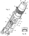
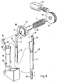
- the lancet device 1 shown in FIG. 1 serves to generate a puncture wound for removing blood for diagnostic purposes.
- Your case 2 has a housing opening 3.
- a puncture wound can be generated by the tip of a lancet which is movable in the housing 2 on a puncture path.
- the housing opening 3 is surrounded by an annular pressure surface 6, with which the lancet device for a puncture against a body part, for example a finger berry, is pressed.
- the skin surface bulges into the housing opening 3.
- the protrusion of the skin facilitates blood leakage, so that already at a comparatively small penetration depth of 0.5 mm to 2 mm a sufficient amount of blood can be removed for diagnostic purposes. By repeatedly pressing against the skin, this effect can be additionally improved ("pumping action").
- a blood drop can also be taken from less well-perfused but also less sensitive to pain, parts of the body.
- the inner diameter of the pressure surface 6 should be quite large, preferably at least 7 mm or even at least 9 mm.
- the pressure surface 6 is inclined inwards towards the housing opening 3.
- a deformable material such as polyurethane or rubber
- the pressure surface is formed there by a component which is referred to as a compression unit because of its pumping action.
- FIG. 2 shows a lancet device 1 with the housing removed
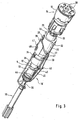
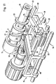
- FIG. 3 shows its lancet drive assembly 10, which is connected to a drum magazine 16.
- the assembly 10 includes a drive rotor 12 which is driven by a drive spring, and a tensioning rotor 13 for tensioning the drive spring.
- the drive spring which is arranged between the drive rotor 12 and the tensioning rotor 13, not shown in Figures 2 and 3.
- the drive spring 11 can only be seen in FIG. It is a torsion spring which is biased and hinged at one end to the drive rotor 12 and at its other end to the tensioning rotor 13.
- a driven side lancet coupling mechanism 24 by which the rotational movement of the rotatable about an axis drive rotor 12 is converted in a drive phase of the lancet drive into a puncture movement in which the lancet is moved at high speed in the puncture direction to a To create a puncture wound.
- the return movement of the lancet is driven and controlled by the rotational movement of the drive rotor 12 by means of the lancet coupling mechanism 24.
- the lancet drive assembly 10 further comprises a further coupling mechanism 38, with which a rotational movement of a rotating component of the lancet drive in a movement of the reference element 14 or another component of a lancet device can be implemented. Since this further coupling mechanism 38 is used in the described embodiment for moving the reference element 14, it is referred to in this context as a reference element coupling mechanism.
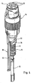
- the reference member is movable relative to the lancet and relative to the housing. It is designed and arranged so that it bears against the skin surface of a patient at the time of puncture of the lancet with its contact surface in a defined position relative to the lancet drive. This ensures that a puncture wound is created with a predetermined puncture depth, which corresponds to the distance between the contact surface of the reference element and the position of the lancet tip extending the most in the puncture direction.
- the reference element 14 includes a drum magazine 16 in which a plurality of lancets can be stored, and a protective cap 17 surrounding the drum magazine 16.
- the contact surface 15 is formed on the protective cap 17, with which the reference element 14 rests against the skin surface.
- a lancet opening 18 is formed, through which the lancet emerges at a puncture in order to produce a puncture wound in a against the housing opening 3 (ie against the pressure surface 6) pressed fingers.
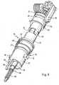
- FIG. 4 shows the reference element 14 with the protective cap 17 removed and its connection to the reference element coupling mechanism 38.
- the drum magazine 16 has a plurality of chambers, in each of which a single lancet is stored. It is also possible, however, to arrange the lancets annularly in a drum magazine 16, which is not divided into individual chambers.
- the number of stored in a drum magazine 16 lancets is largely arbitrary.
- a drum magazine 16 holds three to twelve, more preferably four to eight lancets.
- the drum magazine 16 is rotatable relative to the lancet opening 18 of the protective cap 17 so that outlet openings 20 of the drum magazine 16 can be positioned in sequence for a puncture in alignment with the lancet opening 18.
- the lancet coupling mechanism 24 includes a non-rotatably connected to the housing thrust cylinder 25, from which a coupling rod 26 extends, which is connected during the puncturing and return movement, each with an ("active") lancet.
- the lancet coupling mechanism 24 translates the rotational movement of the drive rotor 12 into a translational movement of the active lancet by means of a cam control.
- the thrust cylinder 25 is provided with a recess in the form of a groove which forms a control cam 27 and by a cam rider 28 of the drive rotor 12 is traversed.
- the cam rider 28 is formed as a control pin which engages in the groove and sits at the end of an outgoing from the drive rotor 12 control arm 29.
- the thrust cylinder 25 is provided with guide elements 32 which engage in axially extending longitudinal grooves in the inner wall of the housing 2 (not shown) to achieve a non-rotatable but in the piercing direction movable connection of the thrust cylinder 25 in the housing 2.
- the guide elements 32 are realized as two guide pins.
- Your control cam 33 is formed by a recess in the form of a groove in the drive rotor 12, in which engages a cam rider 34 in the form of a control pin. It is connected via a coupling arm 35 with a guide rod 36 to which the drum magazine 16 is attached.
- the coupling arm 35 carries the reference member 14.
- the guide rod 36 is rotatable relative to the coupling arm 35 so that the drum magazine 16 in the reference member 14 can be rotated via the guide rod 36, thus using the lancets stored in the drum magazine 16 in turn can be.
- the distance between the drum magazine 16 and the protective cap 17 forming the contact surface 15 is changed by adjusting the length of the reference element 14 by a thread (not shown).
- the setting is made via the in 2 shaft 19 which is connected via a gear 21 with a ring gear 22 of the reference element 14 in engagement.
- the tensioning rotor 13 is set in rotation via a gearbox 37, which is preferably driven by a battery-driven electric motor 40 (FIG. 2).
- the tensioning rotor 13 can also be turned by hand by means of a shaft projecting out of the housing 2.
- the drive rotor 12 and the tensioning rotor 13 first pass through a preparatory rotation angle range in a preparatory phase before the drive spring is tensioned.
- a rotational movement of the clamping rotor 13 via the biased drive spring is transmitted to the drive rotor 12, that during at least part of the preparation phase together (ie simultaneously, but not necessarily, but preferably, synchronously) is rotated with the tensioning rotor 13.
- the movement of the drive rotor 12 in the preparation rotation angle range is converted into a preparatory movement of the coupling rod 26 relative to the drum magazine 16, in which the coupling rod 26 penetrates into a chamber of the drum magazine 16 through an insertion opening (not shown) opposite a lancet opening 18 With locked in a lancet located therein.
- a suitable coupling mechanism are described in WO 02/36010 A1, which is hereby incorporated by reference in the present application.
- the reference member coupling mechanism 38 advances the reference member 14 in the housing 2 toward the housing opening 3 so as to abut the contact surface 15 against the skin of a patient. Due to the size of the inner diameter of the pressure surface 6, the finger berry bulges when creating something in the housing opening 3 of the lancing device 1 (Fig. 1) into it.
- the reference element 14 can therefore abut with its contact surface 15 on the skin, although it is in the housing 2 in a position in which the contact surface 15 extends at a distance behind a plane passing through the inner edge 7 of the pressure surface 6 level.
- the drive rotor 12 When the drive rotor 12 has passed through the preparation rotation angle range, it is locked by means of a blocking element 41, so that during further clamping phase of the lancet drive movement upon further rotation of the drive rotor 13, the drive spring is tensioned.
- the blocking element 41 is formed as a resiliently applied to an inner wall of the housing 2 release tab, which starts from the drive rotor 12 and engages for locking the drive rotor 12 in a recess in the inner wall of the housing.
- the release tongue is made in one piece with the control arm 42 and the control pin 28 as an injection molded part.
- a puncturing movement is initiated after completion of the clamping process in that the blocking element 41 is released from its blocking engagement, so that rotates in the drive phase of the drive rotor 12, driven by the drive spring, very quickly in its rest position. It rotates in the same direction of rotation as the tensioning rotor 13 when tensioning the drive spring.
- This rapid movement of the drive rotor 12 is converted via the lancet coupling mechanism 24 into a puncture and return movement of the lancet and via the reference element coupling mechanism 38 in a return movement of the reference element 14.
- the puncturing process can be triggered (triggered), for example, by pressing the contact surface 15 of the reference element 14 against the skin with a predetermined minimum force.
- the reference element 14 preferably has a pressure sensor with which a signal required for triggering a puncturing movement can be generated as soon as pressure is exerted on the contact surface 15 which exceeds a predetermined minimum contact pressure.
- the pressure sensor can for example be realized in that the contact surface 15 is mounted on a spring and an electrical contact is closed only after compression of the spring.
- a release button 5 can be arranged on the housing 2 of the lancet device 1 (FIG. 1).
- an electrical signal is initially generated in the illustrated embodiment, by which the electric motor 40 is set in motion.
- the tensioning rotor 13 is rotated by a small rotational angle step.
- the tensioning rotor 13 has a release cam 44 which, upon rotation of the tensioning rotor 13, actuates a release mechanism 45 beyond a predetermined angular position by which the previously existing escapement of the drive rotor 12 is released.
- the release mechanism 45 is formed as a rocker which is pivotally mounted about bearing pin 46 on the housing 2.
- the blocking element 41 has a shoulder with a return surface 48.
- the head part 47 is located above the blocking element 41 and presses on the return surface 48 of the release tongue 41, whereby it is released from its engagement with the recess of the housing 3.
- the drive spring relaxes, so that the drive phase of the movement of the lancet drive expires.
- FIG. 5 illustrates the movements of the lancet and the reference element 14, which are driven and controlled by the rotational movement of the drive rotor 12 by means of the coupling mechanisms 24, 38.
- the stroke, that is to say the movement in the axial direction, of the coupling rod 26 is plotted as curve A and the stroke of the reference element 14 as curve B over the rotational angle position of the drive rotor 12.
- a work cycle begins with the beginning of a rotary movement of the tensioning rotor and ends with the end of the return movement of the lancet after the puncture.
- the drive rotor 12 (as set forth above in a relatively slow movement simultaneously with the tensioning rotor) undergoes a preparation rotation angle range ⁇ . It ends at about 120 ° (indicated in Figure 5 by a vertical line).
- the movement of the drive rotor 12 in the preparation rotation angle range is converted by means of the two coupling mechanisms 24, 38 so that both the coupling rod 26 and the reference element 14 in the device are moved forward (towards the housing opening 3) until the contact surface 15 of the reference element 14 bears against the skin and the coupling rod 26 is coupled to a lancet.
- the drive rotational angle range (which corresponds to the drive phase of the lancet drive movement, consisting of puncture and return movement) following the preparation rotational angle range is traversed in less than 100 ms, preferably less than 20 ms.
- FIG. 6 shows a further embodiment of a lancet drive assembly 10. It is shown without the reference element 14, so that the head 50 of the guide rod 36, on which the drum magazine 16 is slipped, and the coupling rod 26, which latches for a puncture with a lancet , are easier to recognize. It can also be seen that the coupling rod head 49 has a thickening, which allows a positive coupling to a lancet. As with the embodiment described with reference to Figures 2 and 3, the arranged between the drive rotor 12 and the tensioning rotor 13 drive spring is not shown.
- the drive rotor 12 and the clamping rotor 13 have stop members 51 which abut each other in a stop position of the rotors 12, 13 and thereby to stop a rotational movement of the drive rotor 12 relative to the tensioning rotor 13.
- stop members 51 are also present in the embodiment described above. They serve in particular to receive the bias of the drive spring and stop the drive rotor 12 at the end of the puncture and return movement.
- a rotational movement of the tensioning rotor 13 is transmitted to the drive rotor 12 via the drive spring 11, so that the tensioning rotor 13 and the drive rotor 12 rotate together in this rotation angle range.
- the bias of the drive spring 11 a close coupling of the clamping rotor 13 is achieved with the drive rotor 12, so that the rotational angular position of the clamping rotor 13 during the common rotation of the rotational angular position of the drive rotor at most by 10 °, preferably at most by 5 °, deviates.
- a sufficiently high bias of the drive spring 11 is used in this way to achieve a largely synchronous, so angular and speed-sensitive movement of the two rotors. This has the advantage that the movements of the coupling mechanisms 24, 38 can be controlled even more precisely.
- synchronous movement of the two rotors 12, 13 may also be achieved by coupling them together while passing through the preparation rotational angle range by a locking bar (not shown).
- this embodiment corresponds largely to the embodiment described with reference to FIGS 2 to 4.
- the reference element coupling mechanism 38 is not used in this design for a quick return movement of the reference element 14 after a puncture, but for a precise setting of the penetration depth by a slow movement of the reference element 14. As FIG.
- the penetration depth depends on the position in which the contact surface 15 of the reference element 14 is relative to the coupling rod 26 when the puncturing movement takes place.
- the reference element 14 is displaced in the axial direction relative to the coupling rod 26 prior to a puncture. This adjustment movement takes place independently of the puncturing movement and can be carried out slowly.
- the set position should not change during the puncturing movement. Therefore, the reference member coupling mechanism 38 is preferably coupled to the tensioning rotor 13, which rotates relatively slowly.
- FIG. 7 shows the movement of the coupling rod 26 and thus also of the lancet as a curve C, as well as the movement of the reference element 14 as a curve D as a function of the angular position of the clamping rotor 13.
- a first portion of the control cam 33 of the reference element coupling mechanism is used to first move the reference element 14 in a maximum position M, which corresponds to a minimum penetration depth. If the tensioning rotor 13 is then further rotated, the reference element 14 is moved back from this maximum position M to a position which corresponds to the desired penetration depth ("puncturing position"). The farther the reference member 14 is retracted relative to the coupling bar 26, the greater the depth of the subsequent puncture. If the puncture position is reached with the desired penetration depth, the electric motor 40 is switched off and the tensioning rotor 13 in this Position locked. After triggering the tensioning rotor 13 terminates its duty cycle by being further rotated in the movement section Q until it reaches its starting position.
- the electric motor 40 drives the tensioning rotor 13 via a two-stage worm gear 37, so that the rotational angular position of the tensioning rotor 13 can be precisely adjusted by electronically counting the revolutions of one or more parts of the worm gear 37.
- FIGS. 2-4 and 6 may be combined so that a first reference element coupling mechanism couples the reference element 14 to the tensioning rotor 13 to adjust the penetration depth prior to initiation of a puncturing motion, and a second reference element coupling mechanism couples the reference element 14 to the tensioning element 13 Drive rotor 12 coupled to move after a puncture, the reference element 14.
- the drive spring is used for a fast return movement, which would be very difficult to realize by an electric motor 40, while the electric motor 40 is used for a slow adjustment movement of the penetration depth, for which the drive spring is less suitable.
- Figures 8 and 9 show a further embodiment of a lancet drive assembly 10.
- the reference element 14 is formed as a sample receiving unit 60 in this embodiment.
- the sample receiving unit 60 includes a guide channel 61 for the lancet 4 and a sample receiving channel 63 having a mouth 63a for receiving a sample.
- the sample receiving unit 60 further includes a reaction zone 64 with reagents to which the sample can be delivered through the sample receiving channel 63.
- the lancet drive assembly 10 includes a drive rotor 12 driven by a drive spring 11 which is rotatable about an axis 59 and a tensioning rotor 13 for tensioning the drive spring 11.
- Drive rotor 12 and tension rotor 13 are coaxially arranged.
- the drive spring 11 is designed as a helical spring leg spring. Alternatively, for example, a coil spring as a drive spring 11 is possible.
- the turns of the drive spring 11 may be spaced to minimize frictional losses, or close to each other to damp torsional vibrations, with tension biasing providing damping friction between the turns.
- the clamping rotor 13 has a stop member in the form of a stopper groove 52 into which a stop pin 53 of the drive rotor 12 engages.
- the stop pin 53 is pressed by the bias of the drive spring 11 against one end of the circular stop 27, to which he strikes in a rest position.
- the reference element coupling mechanism 38 comprises a pivotally suspended about two bearing pin 69 sleeve 65 with a rigid control arm 66 which engages with a control pin as a cam ridge 67 in a formed by a groove-shaped cam 68 of the drive rotor 12.
- the cam 68 has two semi-circular sections with different radii.
- the coupling rod 70 of the lancet coupling mechanism 24 is translationally movable to allow the puncture and return movement of the lancet 4 in the sleeve 65 moves the cam rider 67 between these two sections.
- the coupling rod 70 is driven by the drive rotor 12 via a connecting rod 71.
- the connecting rod 71 carries a crank pin 72 which engages in a bore 75 of the drive rotor 12.
- a second reference element coupling mechanism 39 is provided in the illustrated embodiment, which withdraws the sample receiving unit 60 slightly after the puncturing motion and pushes it forward again after the pivoting movement, a drop of blood can be picked up from the sample receiving channel 63.
- the second reference element coupling mechanism 39 comprises a sleeve 77, from which a rigid control arm 78 with a control pin as cam cam 79 emanates, which engages in a formed by a groove-shaped cam 73 of the drive rotor 12.
- the control cam 68 is arranged on a first side (front side) of the drive rotor 12 and the control cam 73 on its rear side.
- the sleeve 77 is disposed around the coupling rod 70 and in the sleeve 65 of the first reference member coupling mechanism 38.
- the lancet device is attached to a body part of a patient, so that the contact surface 15 of the reference element 14 formed by the sample receiving unit 16 rests against the skin surface.
- the tensioning rotor 13 is rotated by 180 °, while the drive rotor 12 is held by a locking element (not shown).
- the locking element (not shown) is released, so that the drive rotor 12 a snap movement of 180 ° performs until the stop pin 53 abuts against the end of the stop groove 52 of the clamping rotor 53.
- the crank pin 72 describes the lower half of a circular path, so that by means of the connecting rod 71 and the coupling rod 70 of the lancet coupling mechanism 24, the piercing movement of the lancet 4 is performed.
- the second reference member coupling mechanism 39 through the cam 73, causes the sleeve 77 and the sample receiving unit 60 held therein to be withdrawn. Since the contact surface 15 no longer rests on the skin surface, sample liquid can escape.
- the tensioning rotor 13 is again moved by 180 °, wherein the drive rotor 12 follows because of the bias of the drive spring 11 of this 180 ° movement.
- Due to the shape of the cam 68 there is a pivoting movement of the sleeve 65, which is dimensioned so that the mouth 63a ( Figure 10) of the sample receiving unit 60 is aligned with the puncture site.
- the groove 73 causes the sample receiving unit 60 to be pushed forward again via the connecting rod 71 and the coupling rod 70, so that the mouth 63a comes into contact with escaped blood and absorbs it.
- a third groove in the drive rotor can be used to drive the coupling rod 70 via a third cam rider.
- To improve blood leakage may additionally with a pressure piece, for example, the lower edge of the sleeve 77, on the skin surface in the vicinity of the puncture site be acted.
- a pressure piece for example, the lower edge of the sleeve 77
- blood can be squeezed out of the puncture wound, which can be absorbed by the sample receiving unit 60. If the contact force is lowered after blood collection has been completed, then the puncture wound closes.
- the sample receiving unit 60 is additionally provided with a pump plunger 76 (Fig. 10) for enhancing capillary forces of the sample receiving channel 63 by suction forces.
- the sample receiving unit 60 is provided with struts 80 which relax after puncturing and retract the pump plunger 76 so that blood is drawn into the sample receiving channel 63.
- a pumping movement can be realized to support the blood collection, for example by clamping rotor 13 and drive rotor 12 are moved forward and backward over a small angular range. If the bias of the drive spring 11 is so great that the tensioning rotor 12 and the drive rotor 13 move substantially synchronously, in particular their rotational position deviates from each other by at most 10 °, in addition to forward movements and backward movements in precise control of the movements are possible.
- FIG. 11 shows a perspective view of a partial view of a further embodiment of a lancet drive assembly 10 with a drive rotor 12 and a tensioning rotor 13.
- the drive spring is not shown in FIG.
- the peculiarity of the illustrated assembly 10 consists in a lancet coupling mechanism 24 having a lever 81 on which the cam rider 28 is arranged for traversing the cam 27 formed as a groove of the drive rotor 12.
- the lever 81 is rotatably mounted in a pivot point 82, so that the scoring on a flank of the control cam 27 with the lancet holder 83 stroke is increased by a lever ratio.
- the sections 84,85 of the lever 81 on both sides of the pivot point 82 each form a lever arm, so that the stroke increase achieved calculated from the ratio of the lengths of the two lever arms 84,85. These lengths are to be measured outwards from the fulcrum 82, i. E. to the cam rider 28 and the attachment point 86 of the lancet holder 83, which is moved by the lever 81.
- a large stroke can be achieved with the lever ratio described, thus realizing a smaller and more compact hand-held device.
- a large stroke can be achieved only by a relatively large diameter of the corresponding cam 27, otherwise it comes to a self-locking. Namely, the pitch angle of a control cam 27 exceeds a critical value, which depends on the friction coefficient, the cam cam 28 blocks and can not be set in motion by an arbitrarily large torque. With the described leverage can be achieved even with less steeply rising flanks of a cam 27, a large stroke.
- the leverage is part of the lancet coupling mechanism 24, so that by adjusting the pivot point 82, the stitch depth can be adjusted.
- the advantages of the leverage can also be used for another coupling mechanism that is coupled to the drive rotor or the tensioning rotor.
- the pivot point 82 is formed as a pin on a sliding base 87.
- the base 87 can be moved by means of a threaded spindle 88 for adjusting the piercing depth.
- the threaded spindle 88 can be used to adjust the position of the pivot point 82, for example, an eccentric or a wedge.
- the tensioning rotor 13 is passed through the drive rotor 12.
- the tensioning rotor 13 carries a control cam 33, which is traversed by a cam follower 34 of the reference element coupling mechanism 38. If the tensioning rotor 13 is rotated to tension the drive spring, not shown, a reference element carrier 91 is advanced by the reference element coupling mechanism 38.
- the reference element carrier 91 has a latching mechanism 90 in the form of a latching hook, which engages with the housing, not shown. In this way, the reference element is fixed for a puncture with respect to the lancet drive 9 and with respect to the housing, not shown.
- the associated release mechanism may be formed in accordance with the embodiment explained with reference to Figures 1 to 5 and is therefore not shown in Figure 11 for simplicity.
- the tensioning rotor 13 carries a further release cam 93, with which by a suitable mechanism (not shown) of the locking mechanism 90 forming latching hook is released from its latching, so that the reference element support 91 and thus also the reference element can be withdrawn after a puncture.
Landscapes
- Health & Medical Sciences (AREA)
- Life Sciences & Earth Sciences (AREA)
- Heart & Thoracic Surgery (AREA)
- Medical Informatics (AREA)
- Biophysics (AREA)
- Pathology (AREA)
- Engineering & Computer Science (AREA)
- Biomedical Technology (AREA)
- Hematology (AREA)
- Physics & Mathematics (AREA)
- Molecular Biology (AREA)
- Surgery (AREA)
- Animal Behavior & Ethology (AREA)
- General Health & Medical Sciences (AREA)
- Public Health (AREA)
- Veterinary Medicine (AREA)
- Dermatology (AREA)
- Measurement Of The Respiration, Hearing Ability, Form, And Blood Characteristics Of Living Organisms (AREA)
Applications Claiming Priority (1)
| Application Number | Priority Date | Filing Date | Title |
|---|---|---|---|
| DE102004059491A DE102004059491B4 (de) | 2004-12-10 | 2004-12-10 | Lanzettenvorrichtung zum Erzeugen einer Einstichwunde und Lanzettenantriebs-Baugruppe |
Publications (2)
| Publication Number | Publication Date |
|---|---|
| EP1669028A1 true EP1669028A1 (fr) | 2006-06-14 |
| EP1669028B1 EP1669028B1 (fr) | 2008-01-09 |
Family
ID=35965999
Family Applications (1)
| Application Number | Title | Priority Date | Filing Date |
|---|---|---|---|
| EP05025309A Not-in-force EP1669028B1 (fr) | 2004-12-10 | 2005-11-19 | Dispositif lancette pour formation d'une incision et sous-ensemble pour un actioneur d'une lancette |
Country Status (7)
| Country | Link |
|---|---|
| US (2) | US7842060B2 (fr) |
| EP (1) | EP1669028B1 (fr) |
| JP (2) | JP4381372B2 (fr) |
| AT (1) | ATE383109T1 (fr) |
| CA (1) | CA2529241C (fr) |
| DE (2) | DE102004059491B4 (fr) |
| ES (1) | ES2298914T3 (fr) |
Cited By (18)
| Publication number | Priority date | Publication date | Assignee | Title |
|---|---|---|---|---|
| EP1897493A1 (fr) | 2006-09-04 | 2008-03-12 | Roche Diagnostics GmbH | système de piqure pour prélever un fluide organique |
| EP1929948A1 (fr) * | 2006-12-08 | 2008-06-11 | Roche Diagnostics GmbH | Dispositif de perçage |
| WO2008107382A1 (fr) * | 2007-03-05 | 2008-09-12 | Gerresheimer Wilden Gmbh | Dispositif de ponction pour prélèvement sanguin pourvu d'un ressort à branches |
| WO2008131920A2 (fr) | 2007-04-30 | 2008-11-06 | Roche Diagnostics Gmbh | Instrument et système pour produire un échantillon d'un liquide corporel et pour analyser celui-ci |
| EP2039293A1 (fr) * | 2007-09-19 | 2009-03-25 | F. Hoffman-la Roche AG | Entraînement de combinaison pour un système d'obtention d'échantillons pour obtenir un échantillon liquide |
| EP2087840A1 (fr) | 2008-02-11 | 2009-08-12 | F.Hoffmann-La Roche Ag | Procédé et dispositif destinés au prélèvement de liquide corporel |
| WO2009147080A1 (fr) * | 2008-06-06 | 2009-12-10 | Gerresheimer Wilden Gmbh | Dispositif de piqûre et procédé permettant le prélèvement d'un échantillon de sang |
| EP2174591A1 (fr) | 2008-10-09 | 2010-04-14 | Roche Diagnostics GmbH | Appareil de perçage |
| EP2181651A1 (fr) | 2008-10-29 | 2010-05-05 | Roche Diagnostics GmbH | Instrument et système pour produire un échantillon d'un corps liquide et analyse correspondante |
| EP2221000A1 (fr) * | 2007-11-27 | 2010-08-25 | ARKRAY, Inc. | Dispositif de perforation |
| EP2281507A1 (fr) | 2009-08-04 | 2011-02-09 | F. Hoffmann-La Roche AG | Dispositif de commande pour un appareil médical |
| EP2311374A1 (fr) | 2009-10-13 | 2011-04-20 | Roche Diagnostics GmbH | Appareil pour obtention et analyse du sang; mécanisme pour couplage d'une lancette |
| US8828039B2 (en) | 2008-06-06 | 2014-09-09 | Gerresheimer Regensburg Gmbh | Pricking device for taking a blood sample |
| WO2015032747A1 (fr) * | 2013-09-05 | 2015-03-12 | Sanofi-Aventis Deutschland Gmbh | Mécanisme d'entraînement destiné à un agencement d'insertion d'aiguille |
| US9186104B2 (en) | 2007-04-30 | 2015-11-17 | Roche Diabetes Care, Inc. | Instruments and system for producing a sample of a body fluid and for analysis thereof |
| EP3501576A1 (fr) * | 2017-12-19 | 2019-06-26 | Tecpharma Licensing AG | Mécanisme d'insertion et de retrait d'aiguille pour un dispositif d'administration de médicament |
| US10660556B2 (en) | 2013-06-13 | 2020-05-26 | Roche Diabetes Care, Inc. | Body fluid sampling element |
| US10850043B2 (en) | 2013-04-10 | 2020-12-01 | Sanofi | Injection device |
Families Citing this family (135)
| Publication number | Priority date | Publication date | Assignee | Title |
|---|---|---|---|---|
| US6036924A (en) | 1997-12-04 | 2000-03-14 | Hewlett-Packard Company | Cassette of lancet cartridges for sampling blood |
| US6391005B1 (en) | 1998-03-30 | 2002-05-21 | Agilent Technologies, Inc. | Apparatus and method for penetration with shaft having a sensor for sensing penetration depth |
| US8641644B2 (en) | 2000-11-21 | 2014-02-04 | Sanofi-Aventis Deutschland Gmbh | Blood testing apparatus having a rotatable cartridge with multiple lancing elements and testing means |
| US9226699B2 (en) | 2002-04-19 | 2016-01-05 | Sanofi-Aventis Deutschland Gmbh | Body fluid sampling module with a continuous compression tissue interface surface |
| US7981056B2 (en) | 2002-04-19 | 2011-07-19 | Pelikan Technologies, Inc. | Methods and apparatus for lancet actuation |
| WO2002100252A2 (fr) | 2001-06-12 | 2002-12-19 | Pelikan Technologies, Inc. | Appareil de prelevement sanguin et procede connexe |
| US7749174B2 (en) | 2001-06-12 | 2010-07-06 | Pelikan Technologies, Inc. | Method and apparatus for lancet launching device intergrated onto a blood-sampling cartridge |
| US8337419B2 (en) | 2002-04-19 | 2012-12-25 | Sanofi-Aventis Deutschland Gmbh | Tissue penetration device |
| US7041068B2 (en) | 2001-06-12 | 2006-05-09 | Pelikan Technologies, Inc. | Sampling module device and method |
| WO2002100460A2 (fr) | 2001-06-12 | 2002-12-19 | Pelikan Technologies, Inc. | Actionneur electrique de lancette |
| US9427532B2 (en) | 2001-06-12 | 2016-08-30 | Sanofi-Aventis Deutschland Gmbh | Tissue penetration device |
| US9795747B2 (en) | 2010-06-02 | 2017-10-24 | Sanofi-Aventis Deutschland Gmbh | Methods and apparatus for lancet actuation |
| US7699791B2 (en) | 2001-06-12 | 2010-04-20 | Pelikan Technologies, Inc. | Method and apparatus for improving success rate of blood yield from a fingerstick |
| JP4209767B2 (ja) | 2001-06-12 | 2009-01-14 | ペリカン テクノロジーズ インコーポレイテッド | 皮膚の性状の一時的変化に対する適応手段を備えた自動最適化形切開器具 |
| US7004928B2 (en) | 2002-02-08 | 2006-02-28 | Rosedale Medical, Inc. | Autonomous, ambulatory analyte monitor or drug delivery device |
| US7909778B2 (en) | 2002-04-19 | 2011-03-22 | Pelikan Technologies, Inc. | Method and apparatus for penetrating tissue |
| US7232451B2 (en) | 2002-04-19 | 2007-06-19 | Pelikan Technologies, Inc. | Method and apparatus for penetrating tissue |
| US7976476B2 (en) | 2002-04-19 | 2011-07-12 | Pelikan Technologies, Inc. | Device and method for variable speed lancet |
| US7291117B2 (en) | 2002-04-19 | 2007-11-06 | Pelikan Technologies, Inc. | Method and apparatus for penetrating tissue |
| US7175642B2 (en) | 2002-04-19 | 2007-02-13 | Pelikan Technologies, Inc. | Methods and apparatus for lancet actuation |
| US7648468B2 (en) | 2002-04-19 | 2010-01-19 | Pelikon Technologies, Inc. | Method and apparatus for penetrating tissue |
| US7491178B2 (en) | 2002-04-19 | 2009-02-17 | Pelikan Technologies, Inc. | Method and apparatus for penetrating tissue |
| US7674232B2 (en) | 2002-04-19 | 2010-03-09 | Pelikan Technologies, Inc. | Method and apparatus for penetrating tissue |
| US9795334B2 (en) | 2002-04-19 | 2017-10-24 | Sanofi-Aventis Deutschland Gmbh | Method and apparatus for penetrating tissue |
| US7892183B2 (en) | 2002-04-19 | 2011-02-22 | Pelikan Technologies, Inc. | Method and apparatus for body fluid sampling and analyte sensing |
| US8267870B2 (en) | 2002-04-19 | 2012-09-18 | Sanofi-Aventis Deutschland Gmbh | Method and apparatus for body fluid sampling with hybrid actuation |
| US9314194B2 (en) | 2002-04-19 | 2016-04-19 | Sanofi-Aventis Deutschland Gmbh | Tissue penetration device |
| US7331931B2 (en) | 2002-04-19 | 2008-02-19 | Pelikan Technologies, Inc. | Method and apparatus for penetrating tissue |
| US8702624B2 (en) | 2006-09-29 | 2014-04-22 | Sanofi-Aventis Deutschland Gmbh | Analyte measurement device with a single shot actuator |
| US9248267B2 (en) | 2002-04-19 | 2016-02-02 | Sanofi-Aventis Deustchland Gmbh | Tissue penetration device |
| US7708701B2 (en) | 2002-04-19 | 2010-05-04 | Pelikan Technologies, Inc. | Method and apparatus for a multi-use body fluid sampling device |
| US8221334B2 (en) | 2002-04-19 | 2012-07-17 | Sanofi-Aventis Deutschland Gmbh | Method and apparatus for penetrating tissue |
| US7229458B2 (en) | 2002-04-19 | 2007-06-12 | Pelikan Technologies, Inc. | Method and apparatus for penetrating tissue |
| US7901362B2 (en) | 2002-04-19 | 2011-03-08 | Pelikan Technologies, Inc. | Method and apparatus for penetrating tissue |
| US8784335B2 (en) | 2002-04-19 | 2014-07-22 | Sanofi-Aventis Deutschland Gmbh | Body fluid sampling device with a capacitive sensor |
| US7717863B2 (en) | 2002-04-19 | 2010-05-18 | Pelikan Technologies, Inc. | Method and apparatus for penetrating tissue |
| US7297122B2 (en) | 2002-04-19 | 2007-11-20 | Pelikan Technologies, Inc. | Method and apparatus for penetrating tissue |
| US8579831B2 (en) | 2002-04-19 | 2013-11-12 | Sanofi-Aventis Deutschland Gmbh | Method and apparatus for penetrating tissue |
| US7547287B2 (en) | 2002-04-19 | 2009-06-16 | Pelikan Technologies, Inc. | Method and apparatus for penetrating tissue |
| US7371247B2 (en) | 2002-04-19 | 2008-05-13 | Pelikan Technologies, Inc | Method and apparatus for penetrating tissue |
| US7381184B2 (en) | 2002-11-05 | 2008-06-03 | Abbott Diabetes Care Inc. | Sensor inserter assembly |
| US8574895B2 (en) | 2002-12-30 | 2013-11-05 | Sanofi-Aventis Deutschland Gmbh | Method and apparatus using optical techniques to measure analyte levels |
| US7052652B2 (en) | 2003-03-24 | 2006-05-30 | Rosedale Medical, Inc. | Analyte concentration detection devices and methods |
| WO2004107964A2 (fr) | 2003-06-06 | 2004-12-16 | Pelikan Technologies, Inc. | Procede et appareil d'echantillonnage de fluides anatomiques et d'examen de l'analysat |
| WO2006001797A1 (fr) | 2004-06-14 | 2006-01-05 | Pelikan Technologies, Inc. | Element penetrant peu douloureux |
| US8282576B2 (en) | 2003-09-29 | 2012-10-09 | Sanofi-Aventis Deutschland Gmbh | Method and apparatus for an improved sample capture device |
| US9351680B2 (en) | 2003-10-14 | 2016-05-31 | Sanofi-Aventis Deutschland Gmbh | Method and apparatus for a variable user interface |
| USD902408S1 (en) | 2003-11-05 | 2020-11-17 | Abbott Diabetes Care Inc. | Analyte sensor control unit |
| EP1706026B1 (fr) | 2003-12-31 | 2017-03-01 | Sanofi-Aventis Deutschland GmbH | Procédé et appareil permettant d'améliorer le flux fluidique et le prélèvement d'échantillons |
| US7822454B1 (en) | 2005-01-03 | 2010-10-26 | Pelikan Technologies, Inc. | Fluid sampling device with improved analyte detecting member configuration |
| US8828203B2 (en) | 2004-05-20 | 2014-09-09 | Sanofi-Aventis Deutschland Gmbh | Printable hydrogels for biosensors |
| EP1765194A4 (fr) | 2004-06-03 | 2010-09-29 | Pelikan Technologies Inc | Procede et appareil pour la fabrication d'un dispositif d'echantillonnage de liquides |
| DE102004059491B4 (de) | 2004-12-10 | 2008-11-06 | Roche Diagnostics Gmbh | Lanzettenvorrichtung zum Erzeugen einer Einstichwunde und Lanzettenantriebs-Baugruppe |
| US9788771B2 (en) | 2006-10-23 | 2017-10-17 | Abbott Diabetes Care Inc. | Variable speed sensor insertion devices and methods of use |
| US7883464B2 (en) | 2005-09-30 | 2011-02-08 | Abbott Diabetes Care Inc. | Integrated transmitter unit and sensor introducer mechanism and methods of use |
| US8512243B2 (en) | 2005-09-30 | 2013-08-20 | Abbott Diabetes Care Inc. | Integrated introducer and transmitter assembly and methods of use |
| US9743862B2 (en) | 2011-03-31 | 2017-08-29 | Abbott Diabetes Care Inc. | Systems and methods for transcutaneously implanting medical devices |
| US8333714B2 (en) | 2006-09-10 | 2012-12-18 | Abbott Diabetes Care Inc. | Method and system for providing an integrated analyte sensor insertion device and data processing unit |
| US20090105569A1 (en) | 2006-04-28 | 2009-04-23 | Abbott Diabetes Care, Inc. | Introducer Assembly and Methods of Use |
| US10226207B2 (en) | 2004-12-29 | 2019-03-12 | Abbott Diabetes Care Inc. | Sensor inserter having introducer |
| US7731657B2 (en) | 2005-08-30 | 2010-06-08 | Abbott Diabetes Care Inc. | Analyte sensor introducer and methods of use |
| US9398882B2 (en) | 2005-09-30 | 2016-07-26 | Abbott Diabetes Care Inc. | Method and apparatus for providing analyte sensor and data processing device |
| US8029441B2 (en) | 2006-02-28 | 2011-10-04 | Abbott Diabetes Care Inc. | Analyte sensor transmitter unit configuration for a data monitoring and management system |
| US9572534B2 (en) | 2010-06-29 | 2017-02-21 | Abbott Diabetes Care Inc. | Devices, systems and methods for on-skin or on-body mounting of medical devices |
| US7697967B2 (en) | 2005-12-28 | 2010-04-13 | Abbott Diabetes Care Inc. | Method and apparatus for providing analyte sensor insertion |
| US8571624B2 (en) | 2004-12-29 | 2013-10-29 | Abbott Diabetes Care Inc. | Method and apparatus for mounting a data transmission device in a communication system |
| US9259175B2 (en) | 2006-10-23 | 2016-02-16 | Abbott Diabetes Care, Inc. | Flexible patch for fluid delivery and monitoring body analytes |
| US8652831B2 (en) | 2004-12-30 | 2014-02-18 | Sanofi-Aventis Deutschland Gmbh | Method and apparatus for analyte measurement test time |
| US20060281187A1 (en) | 2005-06-13 | 2006-12-14 | Rosedale Medical, Inc. | Analyte detection devices and methods with hematocrit/volume correction and feedback control |
| EP1743577A1 (fr) | 2005-06-23 | 2007-01-17 | Roche Diagnostics GmbH | Dispositif portable permettant l'analyse de fluides corporels |
| US9521968B2 (en) | 2005-09-30 | 2016-12-20 | Abbott Diabetes Care Inc. | Analyte sensor retention mechanism and methods of use |
| US8801631B2 (en) | 2005-09-30 | 2014-08-12 | Intuity Medical, Inc. | Devices and methods for facilitating fluid transport |
| CA2623589C (fr) | 2005-09-30 | 2014-07-22 | Intuity Medical, Inc. | Agents catalytiques pour extraire un echantillon de liquide biologique |
| US11298058B2 (en) | 2005-12-28 | 2022-04-12 | Abbott Diabetes Care Inc. | Method and apparatus for providing analyte sensor insertion |
| CA2636034A1 (fr) | 2005-12-28 | 2007-10-25 | Abbott Diabetes Care Inc. | Insertion d'un dispositif medical |
| EP1917909A1 (fr) * | 2006-10-12 | 2008-05-07 | Roche Diagnostics GmbH | Dispositif et procédé pour l'extraction d'échantillon liquides |
| EP2101654A4 (fr) * | 2007-01-12 | 2013-03-06 | Facet Technologies Llc | Cartouche à lancettes multiples et autopiqueur |
| DE102007024183B4 (de) * | 2007-03-05 | 2011-03-03 | Gerresheimer Regensburg Gmbh | Stechvorrichtung mit Verdrehfeder |
| WO2008150917A1 (fr) | 2007-05-31 | 2008-12-11 | Abbott Diabetes Care, Inc. | Dispositifs d'insertion et procédés |
| US20100094326A1 (en) * | 2007-07-05 | 2010-04-15 | Blackrock Kelso Capital Corporation | Multi-lancet cartridge and lancing device |
| EP2042098A1 (fr) | 2007-09-26 | 2009-04-01 | Roche Diagnostics GmbH | Magasin de lancettes |
| US7766846B2 (en) | 2008-01-28 | 2010-08-03 | Roche Diagnostics Operations, Inc. | Rapid blood expression and sampling |
| US9386944B2 (en) | 2008-04-11 | 2016-07-12 | Sanofi-Aventis Deutschland Gmbh | Method and apparatus for analyte detecting device |
| CN101896121B (zh) * | 2008-05-09 | 2012-02-29 | 松下电器产业株式会社 | 皮肤切开器具以及使用该皮肤切开器具切开皮肤的方法 |
| CN101938941B (zh) * | 2008-05-13 | 2012-07-25 | 松下电器产业株式会社 | 皮肤切开器具 |
| WO2009145920A1 (fr) | 2008-05-30 | 2009-12-03 | Intuity Medical, Inc. | Dispositif de prélèvement de liquide organique et interface de site de prélèvement |
| EP3639744B1 (fr) | 2008-06-06 | 2021-11-24 | Intuity Medical, Inc. | Appareil de mesure du sucre sanguin et methode d'utilisation |
| JP5642066B2 (ja) | 2008-06-06 | 2014-12-17 | インテュイティ メディカル インコーポレイテッド | 体液の試料内に含まれている検体の存在または濃度を決定する検定を行う方法および装置 |
| ATE527007T1 (de) * | 2008-10-07 | 2011-10-15 | Hoffmann La Roche | Insertionsvorrichtung |
| WO2010080584A1 (fr) * | 2008-12-18 | 2010-07-15 | Facet Technologies, Llc | Autopiqueur et lancette |
| US9375169B2 (en) | 2009-01-30 | 2016-06-28 | Sanofi-Aventis Deutschland Gmbh | Cam drive for managing disposable penetrating member actions with a single motor and motor and control system |
| US9402544B2 (en) | 2009-02-03 | 2016-08-02 | Abbott Diabetes Care Inc. | Analyte sensor and apparatus for insertion of the sensor |
| DE102009010999A1 (de) * | 2009-03-02 | 2010-09-09 | Murrplastik Medizintechnik Gmbh | Stechhilfe |
| DE202009003050U1 (de) | 2009-03-06 | 2010-08-12 | Dr. Fritz Faulhaber Gmbh & Co. Kg | Nadel-Einstichvorrichtung für medizinische Geräte |
| DE102009033473A1 (de) | 2009-07-10 | 2011-01-13 | Roche Diagnostics Gmbh | Stechgerät |
| CN102473276B (zh) | 2009-08-31 | 2016-04-13 | 雅培糖尿病护理公司 | 医疗装置及方法 |
| WO2011026130A1 (fr) * | 2009-08-31 | 2011-03-03 | Abbott Diabetes Care Inc. | Dispositif d'insertion comprenant un sous-ensemble rotor |
| WO2011028714A1 (fr) * | 2009-09-02 | 2011-03-10 | Facet Technologies, Llc | Système et procédé d'assemblage d'un autopiqueur à l'aide d'un montage à enroulement de ressort |
| WO2011041531A1 (fr) | 2009-09-30 | 2011-04-07 | Abbott Diabetes Care Inc. | Interconnexion pour dispositif de surveillance de substance à analyser sur un corps |
| EP2311373B1 (fr) * | 2009-10-15 | 2012-08-01 | Roche Diagnostics GmbH | Système de piqûre pour l'extraction d'un liquide corporel |
| GB0919568D0 (en) * | 2009-11-09 | 2009-12-23 | Owen Mumford Ltd | Skin stimulus |
| EP2506768B1 (fr) | 2009-11-30 | 2016-07-06 | Intuity Medical, Inc. | Dispositif et procédé de fourniture de matériau d'étalonnage |
| USD924406S1 (en) | 2010-02-01 | 2021-07-06 | Abbott Diabetes Care Inc. | Analyte sensor inserter |
| WO2011102643A2 (fr) * | 2010-02-16 | 2011-08-25 | Choi In Sang | Système de mesure de la glycémie, appareil de réception de bande, appareil de stockage de bande et appareil de collecte de sang automatique |
| LT3622883T (lt) | 2010-03-24 | 2021-08-25 | Abbott Diabetes Care, Inc. | Medicinos prietaiso įvedikliai ir medicinos prietaisų įvedimo ir naudojimo būdai |
| US8965476B2 (en) | 2010-04-16 | 2015-02-24 | Sanofi-Aventis Deutschland Gmbh | Tissue penetration device |
| WO2011162823A1 (fr) | 2010-06-25 | 2011-12-29 | Intuity Medical, Inc. | Systèmes et procédés de surveillance de substance à analyser |
| US11064921B2 (en) | 2010-06-29 | 2021-07-20 | Abbott Diabetes Care Inc. | Devices, systems and methods for on-skin or on-body mounting of medical devices |
| EP2404632B1 (fr) | 2010-07-10 | 2012-11-21 | Roche Diagnostics GmbH | Système d'insertion pour des aiguilles |
| US8714984B2 (en) * | 2010-07-16 | 2014-05-06 | One World Design and Manufacturing Group, LTD | Injection simulator |
| US9167992B2 (en) * | 2010-11-03 | 2015-10-27 | Roche Diabetes Care, Inc. | Lancet drive system depth control method and test strip location methods |
| US8852123B2 (en) | 2010-12-30 | 2014-10-07 | Roche Diagnostics Operations, Inc. | Handheld medical diagnostic devices housing with sample transfer |
| US8158428B1 (en) | 2010-12-30 | 2012-04-17 | General Electric Company | Methods, systems and apparatus for detecting material defects in combustors of combustion turbine engines |
| US9717452B2 (en) | 2010-12-30 | 2017-08-01 | Roche Diabetes Care, Inc. | Handheld medical diagnostic devices with lancing speed control |
| EP3750480B1 (fr) | 2011-08-03 | 2022-02-02 | Intuity Medical, Inc. | Dispositifs de prélèvement de fluide corporel |
| EP3300658B1 (fr) | 2011-12-11 | 2024-01-17 | Abbott Diabetes Care, Inc. | Procédés pour détecteurs d'analytes |
| US9844331B2 (en) | 2011-12-15 | 2017-12-19 | Facet Technologies, Llc | Latch mechanism for preventing lancet oscillation in a lancing device |
| EP2836124B1 (fr) | 2012-04-11 | 2016-06-08 | Facet Technologies, LLC | Dispositif autopiqueur avec réglage de profondeur de pivot mobile |
| US10456069B2 (en) | 2012-04-12 | 2019-10-29 | Facet Technologies, Llc | Lancing device with side activated charge and eject mechanisms |
| EP3011544A4 (fr) | 2013-06-21 | 2017-02-22 | Intuity Medical, Inc. | Système de surveillance d'analyte à rétroaction audible |
| US9486187B2 (en) * | 2013-09-26 | 2016-11-08 | Covidien Lp | Wind up deployment mechanisms for surgical instruments |
| US10213139B2 (en) | 2015-05-14 | 2019-02-26 | Abbott Diabetes Care Inc. | Systems, devices, and methods for assembling an applicator and sensor control device |
| EP3294134B1 (fr) | 2015-05-14 | 2020-07-08 | Abbott Diabetes Care Inc. | Système d'insertion de dispositif medical compact et procédé associé |
| EP3260147A1 (fr) | 2016-06-23 | 2017-12-27 | TecPharma Licensing AG | Tige de piston segmentée pour dispositif d'administration de médicaments |
| EP3260151A1 (fr) | 2016-06-23 | 2017-12-27 | TecPharma Licensing AG | Mécanisme d'insertion et de retrait d'aiguille pour un dispositif d'administration de médicament |
| EP3260149A1 (fr) | 2016-06-23 | 2017-12-27 | TecPharma Licensing AG | Procédé de fixation d'une cartouche dans un dispositif d'injection |
| EP3260146A1 (fr) | 2016-06-23 | 2017-12-27 | TecPharma Licensing AG | Mécanisme de couplage pour un dispositif d'administration de médicament |
| EP3348284A2 (fr) | 2017-01-12 | 2018-07-18 | Tecpharma Licensing AG | Procédé de stérilisation d'un trajet de fluide pour un dispositif d'injection |
| CN110461217B (zh) | 2017-01-23 | 2022-09-16 | 雅培糖尿病护理公司 | 用于分析物传感器插入的系统、装置和方法 |
| CN108324289B (zh) * | 2018-04-17 | 2020-12-11 | 青岛市市立医院 | 一种医学检验用的血液采集装置 |
| CN109350194A (zh) * | 2018-11-15 | 2019-02-19 | 胜利油田中心医院 | 一种动脉穿刺辅助定位笔 |
| CN109662721B (zh) * | 2019-02-28 | 2024-02-02 | 吉林大学 | 全自动指尖采血用指侧推压器 |
| USD1002852S1 (en) | 2019-06-06 | 2023-10-24 | Abbott Diabetes Care Inc. | Analyte sensor device |
| CN113729885B (zh) * | 2019-12-02 | 2023-01-20 | 北京领健医疗科技有限公司 | 穿刺针、耦合器、导引装置及修复器械 |
| USD999913S1 (en) | 2020-12-21 | 2023-09-26 | Abbott Diabetes Care Inc | Analyte sensor inserter |
Citations (7)
| Publication number | Priority date | Publication date | Assignee | Title |
|---|---|---|---|---|
| US4469110A (en) | 1981-06-25 | 1984-09-04 | Slama Gerard J | Device for causing a pinprick to obtain and to test a drop of blood |
| US4924879A (en) | 1988-10-07 | 1990-05-15 | Brien Walter J O | Blood lancet device |
| DE10026172A1 (de) | 2000-05-26 | 2001-11-29 | Roche Diagnostics Gmbh | System zur Entnahme von Körperflüssigkeit |
| WO2002036010A1 (fr) | 2000-10-31 | 2002-05-10 | Roche Diagnostics Gmbh | Systeme de prelevement de sang |
| US6409740B1 (en) | 1999-10-09 | 2002-06-25 | Roche Diagnostics Gmbh | Blood lancet system for withdrawing blood for diagnostic purposes |
| US6419661B1 (en) | 1999-03-05 | 2002-07-16 | Roche Diagnostics Gmbh | Device for withdrawing blood for diagnostic applications |
| EP1384438A1 (fr) | 2002-05-28 | 2004-01-28 | Roche Diagnostics GmbH | Système de prélèvement du sang |
Family Cites Families (24)
| Publication number | Priority date | Publication date | Assignee | Title |
|---|---|---|---|---|
| DE4320463A1 (de) * | 1993-06-21 | 1994-12-22 | Boehringer Mannheim Gmbh | Blutlanzettenvorrichtung zur Entnahme von Blut für Diagnosezwecke |
| US5350392A (en) * | 1994-02-03 | 1994-09-27 | Miles Inc. | Lancing device with automatic cocking |
| US6332871B1 (en) * | 1996-05-17 | 2001-12-25 | Amira Medical | Blood and interstitial fluid sampling device |
| US6015392A (en) * | 1996-05-17 | 2000-01-18 | Mercury Diagnostics, Inc. | Apparatus for sampling body fluid |
| US6706000B2 (en) * | 1997-11-21 | 2004-03-16 | Amira Medical | Methods and apparatus for expressing body fluid from an incision |
| US5964718A (en) * | 1997-11-21 | 1999-10-12 | Mercury Diagnostics, Inc. | Body fluid sampling device |
| US6086545A (en) * | 1998-04-28 | 2000-07-11 | Amira Medical | Methods and apparatus for suctioning and pumping body fluid from an incision |
| US6591125B1 (en) * | 2000-06-27 | 2003-07-08 | Therasense, Inc. | Small volume in vitro analyte sensor with diffusible or non-leachable redox mediator |
| JP4255556B2 (ja) * | 1999-01-29 | 2009-04-15 | アークレイ株式会社 | ランセット一体型測定装置 |
| US7077828B2 (en) * | 1999-03-05 | 2006-07-18 | Roche Diagnostics Gmbh | Device for withdrawing blood for diagnostic applications |
| WO2002007599A1 (fr) * | 2000-07-26 | 2002-01-31 | Terumo Kabushiki Kaisha | Appareil de mesure d'une composition de liquide organique |
| DE10047419A1 (de) * | 2000-09-26 | 2002-04-11 | Roche Diagnostics Gmbh | Lanzettensystem |
| JP2002168861A (ja) * | 2000-11-28 | 2002-06-14 | Terumo Corp | 成分測定装置 |
| WO2002054952A1 (fr) * | 2001-01-12 | 2002-07-18 | Arkray, Inc. | Dispositif de perforation |
| KR100893275B1 (ko) * | 2001-03-29 | 2009-04-17 | 라이프스캔 스코트랜드 리미티드 | 일체식 샘플 시험용 계측기 |
| JP4182431B2 (ja) | 2001-07-11 | 2008-11-19 | アークレイ株式会社 | 穿刺装置 |
| JP4250698B2 (ja) * | 2001-07-19 | 2009-04-08 | アークレイ株式会社 | 穿刺装置 |
| US20040127818A1 (en) * | 2002-12-27 | 2004-07-01 | Roe Steven N. | Precision depth control lancing tip |
| US7481818B2 (en) * | 2003-10-20 | 2009-01-27 | Lifescan | Lancing device with a floating probe for control of penetration depth |
| US7201723B2 (en) * | 2004-03-25 | 2007-04-10 | Roche Diagnostics Operations, Inc. | Pulsating expression cap |
| WO2005096941A1 (fr) | 2004-04-10 | 2005-10-20 | F. Hoffmann-La Roche Ag | Procede et systeme de prelevement de liquides corporels |
| DE102004042886A1 (de) * | 2004-09-04 | 2006-03-30 | Roche Diagnostics Gmbh | Lanzettenvorrichtung zum Erzeugen einer Einstichwunde |
| DE102004059491B4 (de) * | 2004-12-10 | 2008-11-06 | Roche Diagnostics Gmbh | Lanzettenvorrichtung zum Erzeugen einer Einstichwunde und Lanzettenantriebs-Baugruppe |
| US20070060842A1 (en) * | 2005-08-29 | 2007-03-15 | Manuel Alvarez-Icaza | Lancing cap kit applied pressure sensing cap |
-
2004
- 2004-12-10 DE DE102004059491A patent/DE102004059491B4/de not_active Expired - Fee Related
-
2005
- 2005-11-19 ES ES05025309T patent/ES2298914T3/es active Active
- 2005-11-19 EP EP05025309A patent/EP1669028B1/fr not_active Not-in-force
- 2005-11-19 DE DE502005002484T patent/DE502005002484D1/de active Active
- 2005-11-19 AT AT05025309T patent/ATE383109T1/de not_active IP Right Cessation
- 2005-12-07 CA CA002529241A patent/CA2529241C/fr not_active Expired - Fee Related
- 2005-12-08 JP JP2005354776A patent/JP4381372B2/ja not_active Expired - Fee Related
- 2005-12-09 US US11/298,388 patent/US7842060B2/en not_active Expired - Fee Related
-
2009
- 2009-07-02 JP JP2009157932A patent/JP5100713B2/ja not_active Expired - Fee Related
-
2010
- 2010-03-04 US US12/717,359 patent/US8414609B2/en active Active
Patent Citations (7)
| Publication number | Priority date | Publication date | Assignee | Title |
|---|---|---|---|---|
| US4469110A (en) | 1981-06-25 | 1984-09-04 | Slama Gerard J | Device for causing a pinprick to obtain and to test a drop of blood |
| US4924879A (en) | 1988-10-07 | 1990-05-15 | Brien Walter J O | Blood lancet device |
| US6419661B1 (en) | 1999-03-05 | 2002-07-16 | Roche Diagnostics Gmbh | Device for withdrawing blood for diagnostic applications |
| US6409740B1 (en) | 1999-10-09 | 2002-06-25 | Roche Diagnostics Gmbh | Blood lancet system for withdrawing blood for diagnostic purposes |
| DE10026172A1 (de) | 2000-05-26 | 2001-11-29 | Roche Diagnostics Gmbh | System zur Entnahme von Körperflüssigkeit |
| WO2002036010A1 (fr) | 2000-10-31 | 2002-05-10 | Roche Diagnostics Gmbh | Systeme de prelevement de sang |
| EP1384438A1 (fr) | 2002-05-28 | 2004-01-28 | Roche Diagnostics GmbH | Système de prélèvement du sang |
Cited By (35)
| Publication number | Priority date | Publication date | Assignee | Title |
|---|---|---|---|---|
| EP2314206A1 (fr) * | 2006-09-04 | 2011-04-27 | Roche Diagnostics GmbH | Système de piqûre pour l'extraction d'un liquide corporel |
| WO2008028571A1 (fr) * | 2006-09-04 | 2008-03-13 | Roche Diagnostics Gmbh | Système de piqûre pour le prélèvement d'un liquide corporel |
| US8444574B2 (en) | 2006-09-04 | 2013-05-21 | Roche Diagnostics Operations, Inc. | Lancing system for the extraction of a body fluid |
| EP1897493A1 (fr) | 2006-09-04 | 2008-03-12 | Roche Diagnostics GmbH | système de piqure pour prélever un fluide organique |
| EP1929948A1 (fr) * | 2006-12-08 | 2008-06-11 | Roche Diagnostics GmbH | Dispositif de perçage |
| WO2008067914A1 (fr) * | 2006-12-08 | 2008-06-12 | Roche Diagnostics Gmbh | Appareil de ponction |
| WO2008107382A1 (fr) * | 2007-03-05 | 2008-09-12 | Gerresheimer Wilden Gmbh | Dispositif de ponction pour prélèvement sanguin pourvu d'un ressort à branches |
| WO2008131920A2 (fr) | 2007-04-30 | 2008-11-06 | Roche Diagnostics Gmbh | Instrument et système pour produire un échantillon d'un liquide corporel et pour analyser celui-ci |
| US9186104B2 (en) | 2007-04-30 | 2015-11-17 | Roche Diabetes Care, Inc. | Instruments and system for producing a sample of a body fluid and for analysis thereof |
| EP2039293A1 (fr) * | 2007-09-19 | 2009-03-25 | F. Hoffman-la Roche AG | Entraînement de combinaison pour un système d'obtention d'échantillons pour obtenir un échantillon liquide |
| WO2009037341A1 (fr) * | 2007-09-19 | 2009-03-26 | F. Hoffmann La-Roche Ag | Entraînement combiné pour un système de prélèvement d'échantillon pour prélever un échantillon liquide |
| US9017620B2 (en) | 2007-09-19 | 2015-04-28 | Roche Diagnostics Operations, Inc. | Combination drive for a sampling system for collecting a liquid sample |
| EP2221000A1 (fr) * | 2007-11-27 | 2010-08-25 | ARKRAY, Inc. | Dispositif de perforation |
| US8308747B2 (en) | 2007-11-27 | 2012-11-13 | Arkray, Inc. | Puncture device |
| EP2221000A4 (fr) * | 2007-11-27 | 2011-09-07 | Arkray Inc | Dispositif de perforation |
| EP2087840A1 (fr) | 2008-02-11 | 2009-08-12 | F.Hoffmann-La Roche Ag | Procédé et dispositif destinés au prélèvement de liquide corporel |
| US8827925B2 (en) | 2008-06-06 | 2014-09-09 | Gerresheimer Regensburg Gmbh | Pricking device and method for taking a blood sample |
| US8828039B2 (en) | 2008-06-06 | 2014-09-09 | Gerresheimer Regensburg Gmbh | Pricking device for taking a blood sample |
| WO2009147080A1 (fr) * | 2008-06-06 | 2009-12-10 | Gerresheimer Wilden Gmbh | Dispositif de piqûre et procédé permettant le prélèvement d'un échantillon de sang |
| CN102083368B (zh) * | 2008-06-06 | 2015-04-29 | 格雷斯海姆雷根斯堡股份有限公司 | 用于采集血样的刺扎装置 |
| EP2174591A1 (fr) | 2008-10-09 | 2010-04-14 | Roche Diagnostics GmbH | Appareil de perçage |
| EP2548508A1 (fr) | 2008-10-29 | 2013-01-23 | Roche Diagnostics GmbH | Instrument et système pour produire un échantillon dýun corps liquide et analyse correspondante |
| EP2181651A1 (fr) | 2008-10-29 | 2010-05-05 | Roche Diagnostics GmbH | Instrument et système pour produire un échantillon d'un corps liquide et analyse correspondante |
| US9289162B2 (en) * | 2009-08-04 | 2016-03-22 | Roche Diabetes Care, Inc. | Control device for a medical test system |
| EP2281507A1 (fr) | 2009-08-04 | 2011-02-09 | F. Hoffmann-La Roche AG | Dispositif de commande pour un appareil médical |
| WO2011015585A1 (fr) | 2009-08-04 | 2011-02-10 | Roche Diagnostics Gmbh | Dispositif de commande pour un système de test médical |
| US20120165698A1 (en) * | 2009-08-04 | 2012-06-28 | Hans-Juergen Kuhr | Control device for a medical test system |
| EP2311374A1 (fr) | 2009-10-13 | 2011-04-20 | Roche Diagnostics GmbH | Appareil pour obtention et analyse du sang; mécanisme pour couplage d'une lancette |
| WO2011044971A2 (fr) | 2009-10-13 | 2011-04-21 | Roche Diagnostics Gmbh | Dispositif de recueillement et d'analyse d'un échantillon sanguin; mécanisme d'accouplement de lancettes |
| US10456070B2 (en) | 2009-10-13 | 2019-10-29 | Roche Diabetes Care, Inc. | Apparatus for obtaining and analyzing a blood sample with a lancet coupling mechanism |
| US10850043B2 (en) | 2013-04-10 | 2020-12-01 | Sanofi | Injection device |
| US10660556B2 (en) | 2013-06-13 | 2020-05-26 | Roche Diabetes Care, Inc. | Body fluid sampling element |
| WO2015032747A1 (fr) * | 2013-09-05 | 2015-03-12 | Sanofi-Aventis Deutschland Gmbh | Mécanisme d'entraînement destiné à un agencement d'insertion d'aiguille |
| US10173001B2 (en) | 2013-09-05 | 2019-01-08 | Sanofi-Aventis Deutschland | Drive mechanism for a needle insertion arrangement |
| EP3501576A1 (fr) * | 2017-12-19 | 2019-06-26 | Tecpharma Licensing AG | Mécanisme d'insertion et de retrait d'aiguille pour un dispositif d'administration de médicament |
Also Published As
| Publication number | Publication date |
|---|---|
| ATE383109T1 (de) | 2008-01-15 |
| US20060155317A1 (en) | 2006-07-13 |
| JP4381372B2 (ja) | 2009-12-09 |
| EP1669028B1 (fr) | 2008-01-09 |
| CA2529241A1 (fr) | 2006-06-10 |
| JP2006192257A (ja) | 2006-07-27 |
| ES2298914T3 (es) | 2008-05-16 |
| DE102004059491A1 (de) | 2006-07-06 |
| US8414609B2 (en) | 2013-04-09 |
| US7842060B2 (en) | 2010-11-30 |
| DE102004059491B4 (de) | 2008-11-06 |
| CA2529241C (fr) | 2009-03-03 |
| JP5100713B2 (ja) | 2012-12-19 |
| DE502005002484D1 (de) | 2008-02-21 |
| JP2009213933A (ja) | 2009-09-24 |
| US20100168618A1 (en) | 2010-07-01 |
Similar Documents
| Publication | Publication Date | Title |
|---|---|---|
| EP1669028B1 (fr) | Dispositif lancette pour formation d'une incision et sous-ensemble pour un actioneur d'une lancette | |
| EP1254632B1 (fr) | Lancette de prélèvement sanguin avec un mécanisme de pivot | |
| EP2082685B1 (fr) | Système de prise de sang | |
| DE60218170T2 (de) | Durchstechvorrichtung | |
| EP1865846B1 (fr) | Systeme de piqure destine au prelevement d'un liquide organique | |
| EP0565970B1 (fr) | Dispositif pour le prélèvement de sang destiné à un but diagnostique | |
| EP1504718B1 (fr) | Système de prélèvement du sang | |
| DE60317997T2 (de) | Lanzette | |
| EP2174591B1 (fr) | Appareil de perçage | |
| EP2320797B1 (fr) | Dispositif de piqûre permettant le prélèvement d'un échantillon de sang | |
| EP1797822A1 (fr) | Système pour obtenir un échantillon de fluide corporel par perforation de la peau | |
| DE19948759A1 (de) | Blutlanzettenvorrichtung zur Entnahme von Blut für Diagnosezwecke | |
| WO2009043415A1 (fr) | Magasin à lancettes | |
| DE10245721A1 (de) | Stechvorrichtung zur Verwendung bei der Entnahme einer Minimalmenge von Blut zu Analysezwecken | |
| DE10053974A1 (de) | System zur Blutentnahme | |
| EP1897493B1 (fr) | système de piqure pour prélever un fluide organique | |
| EP2311373B1 (fr) | Système de piqûre pour l'extraction d'un liquide corporel | |
| EP2311374A1 (fr) | Appareil pour obtention et analyse du sang; mécanisme pour couplage d'une lancette | |
| EP1992283A1 (fr) | Système de connexion | |
| DE102012107747B4 (de) | Stechhilfe zur Gewinnung von Körperflüssigkeitsproben | |
| DE102004064136B4 (de) | Lanzettenvorrichtung zum Erzeugen einer Einstichwunde | |
| EP4241824A1 (fr) | Dispositif à main permettant d'effectuer localement une ponction d'une peau |
Legal Events
| Date | Code | Title | Description |
|---|---|---|---|
| PUAI | Public reference made under article 153(3) epc to a published international application that has entered the european phase |
Free format text: ORIGINAL CODE: 0009012 |
|
| AK | Designated contracting states |
Kind code of ref document: A1 Designated state(s): AT BE BG CH CY CZ DE DK EE ES FI FR GB GR HU IE IS IT LI LT LU LV MC NL PL PT RO SE SI SK TR |
|
| AX | Request for extension of the european patent |
Extension state: AL BA HR MK YU |
|
| RAP1 | Party data changed (applicant data changed or rights of an application transferred) |
Owner name: F.HOFFMANN-LA ROCHE AG Owner name: ROCHE DIAGNOSTICS GMBH |
|
| 17P | Request for examination filed |
Effective date: 20060824 |
|
| 17Q | First examination report despatched |
Effective date: 20060922 |
|
| AKX | Designation fees paid |
Designated state(s): AT BE BG CH CY CZ DE DK EE ES FI FR GB GR HU IE IS IT LI LT LU LV MC NL PL PT RO SE SI SK TR |
|
| GRAP | Despatch of communication of intention to grant a patent |
Free format text: ORIGINAL CODE: EPIDOSNIGR1 |
|
| GRAS | Grant fee paid |
Free format text: ORIGINAL CODE: EPIDOSNIGR3 |
|
| GRAA | (expected) grant |
Free format text: ORIGINAL CODE: 0009210 |
|
| AK | Designated contracting states |
Kind code of ref document: B1 Designated state(s): AT BE BG CH CY CZ DE DK EE ES FI FR GB GR HU IE IS IT LI LT LU LV MC NL PL PT RO SE SI SK TR |
|
| REG | Reference to a national code |
Ref country code: GB Ref legal event code: FG4D Free format text: NOT ENGLISH |
|
| REG | Reference to a national code |
Ref country code: CH Ref legal event code: EP Ref country code: CH Ref legal event code: NV Representative=s name: A. BRAUN, BRAUN, HERITIER, ESCHMANN AG PATENTANWAE |
|
| REG | Reference to a national code |
Ref country code: IE Ref legal event code: FG4D Free format text: LANGUAGE OF EP DOCUMENT: GERMAN |
|
| REF | Corresponds to: |
Ref document number: 502005002484 Country of ref document: DE Date of ref document: 20080221 Kind code of ref document: P |
|
| REG | Reference to a national code |
Ref country code: ES Ref legal event code: FG2A Ref document number: 2298914 Country of ref document: ES Kind code of ref document: T3 |
|
| PG25 | Lapsed in a contracting state [announced via postgrant information from national office to epo] |
Ref country code: NL Free format text: LAPSE BECAUSE OF FAILURE TO SUBMIT A TRANSLATION OF THE DESCRIPTION OR TO PAY THE FEE WITHIN THE PRESCRIBED TIME-LIMIT Effective date: 20080109 Ref country code: SI Free format text: LAPSE BECAUSE OF FAILURE TO SUBMIT A TRANSLATION OF THE DESCRIPTION OR TO PAY THE FEE WITHIN THE PRESCRIBED TIME-LIMIT Effective date: 20080109 |
|
| REG | Reference to a national code |
Ref country code: CH Ref legal event code: PFA Owner name: F.HOFFMANN-LA ROCHE AG Free format text: F.HOFFMANN-LA ROCHE AG#GRENZACHERSTRASSE 124#4070 BASEL (CH) -TRANSFER TO- F.HOFFMANN-LA ROCHE AG#GRENZACHERSTRASSE 124#4070 BASEL (CH) |
|
| NLV1 | Nl: lapsed or annulled due to failure to fulfill the requirements of art. 29p and 29m of the patents act | ||
| PG25 | Lapsed in a contracting state [announced via postgrant information from national office to epo] |
Ref country code: FI Free format text: LAPSE BECAUSE OF FAILURE TO SUBMIT A TRANSLATION OF THE DESCRIPTION OR TO PAY THE FEE WITHIN THE PRESCRIBED TIME-LIMIT Effective date: 20080109 Ref country code: IS Free format text: LAPSE BECAUSE OF FAILURE TO SUBMIT A TRANSLATION OF THE DESCRIPTION OR TO PAY THE FEE WITHIN THE PRESCRIBED TIME-LIMIT Effective date: 20080509 Ref country code: LT Free format text: LAPSE BECAUSE OF FAILURE TO SUBMIT A TRANSLATION OF THE DESCRIPTION OR TO PAY THE FEE WITHIN THE PRESCRIBED TIME-LIMIT Effective date: 20080109 |
|
| ET | Fr: translation filed | ||
| PG25 | Lapsed in a contracting state [announced via postgrant information from national office to epo] |
Ref country code: BG Free format text: LAPSE BECAUSE OF FAILURE TO SUBMIT A TRANSLATION OF THE DESCRIPTION OR TO PAY THE FEE WITHIN THE PRESCRIBED TIME-LIMIT Effective date: 20080409 |
|
| PG25 | Lapsed in a contracting state [announced via postgrant information from national office to epo] |
Ref country code: PL Free format text: LAPSE BECAUSE OF FAILURE TO SUBMIT A TRANSLATION OF THE DESCRIPTION OR TO PAY THE FEE WITHIN THE PRESCRIBED TIME-LIMIT Effective date: 20080109 Ref country code: LV Free format text: LAPSE BECAUSE OF FAILURE TO SUBMIT A TRANSLATION OF THE DESCRIPTION OR TO PAY THE FEE WITHIN THE PRESCRIBED TIME-LIMIT Effective date: 20080109 |
|
| REG | Reference to a national code |
Ref country code: IE Ref legal event code: FD4D |
|
| PG25 | Lapsed in a contracting state [announced via postgrant information from national office to epo] |
Ref country code: SK Free format text: LAPSE BECAUSE OF FAILURE TO SUBMIT A TRANSLATION OF THE DESCRIPTION OR TO PAY THE FEE WITHIN THE PRESCRIBED TIME-LIMIT Effective date: 20080109 Ref country code: DK Free format text: LAPSE BECAUSE OF FAILURE TO SUBMIT A TRANSLATION OF THE DESCRIPTION OR TO PAY THE FEE WITHIN THE PRESCRIBED TIME-LIMIT Effective date: 20080109 Ref country code: IE Free format text: LAPSE BECAUSE OF FAILURE TO SUBMIT A TRANSLATION OF THE DESCRIPTION OR TO PAY THE FEE WITHIN THE PRESCRIBED TIME-LIMIT Effective date: 20080109 Ref country code: SE Free format text: LAPSE BECAUSE OF FAILURE TO SUBMIT A TRANSLATION OF THE DESCRIPTION OR TO PAY THE FEE WITHIN THE PRESCRIBED TIME-LIMIT Effective date: 20080409 Ref country code: CZ Free format text: LAPSE BECAUSE OF FAILURE TO SUBMIT A TRANSLATION OF THE DESCRIPTION OR TO PAY THE FEE WITHIN THE PRESCRIBED TIME-LIMIT Effective date: 20080109 |
|
| PLBE | No opposition filed within time limit |
Free format text: ORIGINAL CODE: 0009261 |
|
| STAA | Information on the status of an ep patent application or granted ep patent |
Free format text: STATUS: NO OPPOSITION FILED WITHIN TIME LIMIT |
|
| PG25 | Lapsed in a contracting state [announced via postgrant information from national office to epo] |
Ref country code: RO Free format text: LAPSE BECAUSE OF FAILURE TO SUBMIT A TRANSLATION OF THE DESCRIPTION OR TO PAY THE FEE WITHIN THE PRESCRIBED TIME-LIMIT Effective date: 20080109 |
|
| 26N | No opposition filed |
Effective date: 20081010 |
|
| PG25 | Lapsed in a contracting state [announced via postgrant information from national office to epo] |
Ref country code: EE Free format text: LAPSE BECAUSE OF FAILURE TO SUBMIT A TRANSLATION OF THE DESCRIPTION OR TO PAY THE FEE WITHIN THE PRESCRIBED TIME-LIMIT Effective date: 20080109 |
|
| BERE | Be: lapsed |
Owner name: F.HOFFMANN-LA ROCHE A.G. Effective date: 20081130 Owner name: ROCHE DIAGNOSTICS G.M.B.H. Effective date: 20081130 |
|
| PG25 | Lapsed in a contracting state [announced via postgrant information from national office to epo] |
Ref country code: MC Free format text: LAPSE BECAUSE OF NON-PAYMENT OF DUE FEES Effective date: 20081130 |
|
| PG25 | Lapsed in a contracting state [announced via postgrant information from national office to epo] |
Ref country code: CY Free format text: LAPSE BECAUSE OF FAILURE TO SUBMIT A TRANSLATION OF THE DESCRIPTION OR TO PAY THE FEE WITHIN THE PRESCRIBED TIME-LIMIT Effective date: 20080109 |
|
| PG25 | Lapsed in a contracting state [announced via postgrant information from national office to epo] |
Ref country code: BE Free format text: LAPSE BECAUSE OF NON-PAYMENT OF DUE FEES Effective date: 20081130 |
|
| PGFP | Annual fee paid to national office [announced via postgrant information from national office to epo] |
Ref country code: AT Payment date: 20091007 Year of fee payment: 5 Ref country code: CH Payment date: 20091026 Year of fee payment: 5 |
|
| PG25 | Lapsed in a contracting state [announced via postgrant information from national office to epo] |
Ref country code: HU Free format text: LAPSE BECAUSE OF FAILURE TO SUBMIT A TRANSLATION OF THE DESCRIPTION OR TO PAY THE FEE WITHIN THE PRESCRIBED TIME-LIMIT Effective date: 20080710 Ref country code: LU Free format text: LAPSE BECAUSE OF NON-PAYMENT OF DUE FEES Effective date: 20081119 |
|
| PG25 | Lapsed in a contracting state [announced via postgrant information from national office to epo] |
Ref country code: TR Free format text: LAPSE BECAUSE OF FAILURE TO SUBMIT A TRANSLATION OF THE DESCRIPTION OR TO PAY THE FEE WITHIN THE PRESCRIBED TIME-LIMIT Effective date: 20080109 |
|
| PG25 | Lapsed in a contracting state [announced via postgrant information from national office to epo] |
Ref country code: GR Free format text: LAPSE BECAUSE OF FAILURE TO SUBMIT A TRANSLATION OF THE DESCRIPTION OR TO PAY THE FEE WITHIN THE PRESCRIBED TIME-LIMIT Effective date: 20080410 |
|
| REG | Reference to a national code |
Ref country code: CH Ref legal event code: PL |
|
| PG25 | Lapsed in a contracting state [announced via postgrant information from national office to epo] |
Ref country code: CH Free format text: LAPSE BECAUSE OF NON-PAYMENT OF DUE FEES Effective date: 20101130 Ref country code: LI Free format text: LAPSE BECAUSE OF NON-PAYMENT OF DUE FEES Effective date: 20101130 |
|
| PG25 | Lapsed in a contracting state [announced via postgrant information from national office to epo] |
Ref country code: AT Free format text: LAPSE BECAUSE OF NON-PAYMENT OF DUE FEES Effective date: 20101119 |
|
| PG25 | Lapsed in a contracting state [announced via postgrant information from national office to epo] |
Ref country code: PT Free format text: LAPSE BECAUSE OF FAILURE TO SUBMIT A TRANSLATION OF THE DESCRIPTION OR TO PAY THE FEE WITHIN THE PRESCRIBED TIME-LIMIT Effective date: 20080109 |
|
| REG | Reference to a national code |
Ref country code: FR Ref legal event code: PLFP Year of fee payment: 11 |
|
| REG | Reference to a national code |
Ref country code: DE Ref legal event code: R081 Ref document number: 502005002484 Country of ref document: DE Owner name: ROCHE DIABETES CARE GMBH, DE Free format text: FORMER OWNER: ROCHE DIAGNOSTICS GMBH, 68305 MANNHEIM, DE |
|
| REG | Reference to a national code |
Ref country code: FR Ref legal event code: PLFP Year of fee payment: 12 |
|
| REG | Reference to a national code |
Ref country code: FR Ref legal event code: PLFP Year of fee payment: 13 |
|
| REG | Reference to a national code |
Ref country code: FR Ref legal event code: PLFP Year of fee payment: 14 |
|
| PGFP | Annual fee paid to national office [announced via postgrant information from national office to epo] |
Ref country code: IT Payment date: 20201117 Year of fee payment: 16 Ref country code: GB Payment date: 20201029 Year of fee payment: 16 Ref country code: FR Payment date: 20201023 Year of fee payment: 16 Ref country code: ES Payment date: 20201202 Year of fee payment: 16 Ref country code: DE Payment date: 20201013 Year of fee payment: 16 |
|
| REG | Reference to a national code |
Ref country code: DE Ref legal event code: R119 Ref document number: 502005002484 Country of ref document: DE |
|
| GBPC | Gb: european patent ceased through non-payment of renewal fee |
Effective date: 20211119 |
|
| PG25 | Lapsed in a contracting state [announced via postgrant information from national office to epo] |
Ref country code: GB Free format text: LAPSE BECAUSE OF NON-PAYMENT OF DUE FEES Effective date: 20211119 Ref country code: DE Free format text: LAPSE BECAUSE OF NON-PAYMENT OF DUE FEES Effective date: 20220601 |
|
| PG25 | Lapsed in a contracting state [announced via postgrant information from national office to epo] |
Ref country code: FR Free format text: LAPSE BECAUSE OF NON-PAYMENT OF DUE FEES Effective date: 20211130 |
|
| PG25 | Lapsed in a contracting state [announced via postgrant information from national office to epo] |
Ref country code: IT Free format text: LAPSE BECAUSE OF NON-PAYMENT OF DUE FEES Effective date: 20211119 |
|
| REG | Reference to a national code |
Ref country code: ES Ref legal event code: FD2A Effective date: 20230213 |
|
| PG25 | Lapsed in a contracting state [announced via postgrant information from national office to epo] |
Ref country code: ES Free format text: LAPSE BECAUSE OF NON-PAYMENT OF DUE FEES Effective date: 20211120 |