EP2180377B1 - Entwicklungsvorrichtung einer Bilderzeugungsvorrichtung - Google Patents
Entwicklungsvorrichtung einer Bilderzeugungsvorrichtung Download PDFInfo
- Publication number
- EP2180377B1 EP2180377B1 EP09171348.7A EP09171348A EP2180377B1 EP 2180377 B1 EP2180377 B1 EP 2180377B1 EP 09171348 A EP09171348 A EP 09171348A EP 2180377 B1 EP2180377 B1 EP 2180377B1
- Authority
- EP
- European Patent Office
- Prior art keywords
- developer
- developing device
- receiving chamber
- inlet
- delivery unit
- Prior art date
- Legal status (The legal status is an assumption and is not a legal conclusion. Google has not performed a legal analysis and makes no representation as to the accuracy of the status listed.)
- Not-in-force
Links
Images



Classifications
-
- G—PHYSICS
- G03—PHOTOGRAPHY; CINEMATOGRAPHY; ANALOGOUS TECHNIQUES USING WAVES OTHER THAN OPTICAL WAVES; ELECTROGRAPHY; HOLOGRAPHY
- G03G—ELECTROGRAPHY; ELECTROPHOTOGRAPHY; MAGNETOGRAPHY
- G03G15/00—Apparatus for electrographic processes using a charge pattern
- G03G15/06—Apparatus for electrographic processes using a charge pattern for developing
- G03G15/08—Apparatus for electrographic processes using a charge pattern for developing using a solid developer, e.g. powder developer
- G03G15/0896—Arrangements or disposition of the complete developer unit or parts thereof not provided for by groups G03G15/08 - G03G15/0894
-
- G—PHYSICS
- G03—PHOTOGRAPHY; CINEMATOGRAPHY; ANALOGOUS TECHNIQUES USING WAVES OTHER THAN OPTICAL WAVES; ELECTROGRAPHY; HOLOGRAPHY
- G03G—ELECTROGRAPHY; ELECTROPHOTOGRAPHY; MAGNETOGRAPHY
- G03G15/00—Apparatus for electrographic processes using a charge pattern
- G03G15/06—Apparatus for electrographic processes using a charge pattern for developing
- G03G15/08—Apparatus for electrographic processes using a charge pattern for developing using a solid developer, e.g. powder developer
- G03G15/0822—Arrangements for preparing, mixing, supplying or dispensing developer
-
- G—PHYSICS
- G03—PHOTOGRAPHY; CINEMATOGRAPHY; ANALOGOUS TECHNIQUES USING WAVES OTHER THAN OPTICAL WAVES; ELECTROGRAPHY; HOLOGRAPHY
- G03G—ELECTROGRAPHY; ELECTROPHOTOGRAPHY; MAGNETOGRAPHY
- G03G15/00—Apparatus for electrographic processes using a charge pattern
- G03G15/06—Apparatus for electrographic processes using a charge pattern for developing
- G03G15/08—Apparatus for electrographic processes using a charge pattern for developing using a solid developer, e.g. powder developer
- G03G15/0822—Arrangements for preparing, mixing, supplying or dispensing developer
- G03G15/0865—Arrangements for supplying new developer
-
- G—PHYSICS
- G03—PHOTOGRAPHY; CINEMATOGRAPHY; ANALOGOUS TECHNIQUES USING WAVES OTHER THAN OPTICAL WAVES; ELECTROGRAPHY; HOLOGRAPHY
- G03G—ELECTROGRAPHY; ELECTROPHOTOGRAPHY; MAGNETOGRAPHY
- G03G15/00—Apparatus for electrographic processes using a charge pattern
- G03G15/06—Apparatus for electrographic processes using a charge pattern for developing
- G03G15/08—Apparatus for electrographic processes using a charge pattern for developing using a solid developer, e.g. powder developer
- G03G15/0822—Arrangements for preparing, mixing, supplying or dispensing developer
- G03G15/0887—Arrangements for conveying and conditioning developer in the developing unit, e.g. agitating, removing impurities or humidity
-
- G—PHYSICS
- G03—PHOTOGRAPHY; CINEMATOGRAPHY; ANALOGOUS TECHNIQUES USING WAVES OTHER THAN OPTICAL WAVES; ELECTROGRAPHY; HOLOGRAPHY
- G03G—ELECTROGRAPHY; ELECTROPHOTOGRAPHY; MAGNETOGRAPHY
- G03G2215/00—Apparatus for electrophotographic processes
- G03G2215/08—Details of powder developing device not concerning the development directly
- G03G2215/0802—Arrangements for agitating or circulating developer material
- G03G2215/0836—Way of functioning of agitator means
- G03G2215/0841—Presentation of developer to donor member
- G03G2215/0844—Presentation of developer to donor member by upward movement of agitator member
Definitions
- the present general inventive concept relates to a developing device, and, more particularly, to a developing device having an improved developer delivery configuration.
- Image forming apparatuses are used to form an image on a printing medium according to input signals.
- Examples of image forming apparatuses may include printers, copiers, facsimiles, etc., and devices combining functions thereof.
- an electro-photographic image forming apparatus which is one type of image forming apparatus
- light is irradiated to a photoconductor charged with a predetermined electric potential to form an electrostatic latent image on a surface of the photoconductor, and a developer is fed to the electrostatic latent to form a visible image.
- the visible image, formed on the photoconductor is transferred to a printing medium directly or by way of an intermediate transfer unit. After being transferred to the printing medium, the image is fixed to the printing medium via a fixing process.
- a developing device includes a developer receiving chamber in which a developer to be fed to the photoconductor is stored, and a feed tool and developing tool provided in proximity to the developer receiving chamber.
- the feed tool feeds the developer stored in the developer receiving chamber to the developing tool, and the developing tool attaches the developer to the surface of the photoconductor on which the electrostatic latent image is formed so as to form a visible image.
- US 2006/0018673 A1 describes an image forming apparatus with a developer cartridge mounted onto the device comprising a developer supply part, said supply part being controlled by a sensor and driving motor to maintain the amount of developer supplied during printing within a range optimum for uniform density of developer.
- US 2005/100366 A1 describes a toner/developer mixing roller disposed within an image forming apparatus to supply a uniform mixture of toner and developer to a developer roller.
- US 2007/0025773 A1 describes a developing device comprising three sections with partitioning walls dividing three augers, wherein a toner concentration detector is disposed in the third section which alters the amount of toner fed into the device.
- JP 2001175082 describes a toner recycling system for an image forming device comprising a plurality of delivery units separated by walls.
- At lease one feature of embodiments of the present general inventive concept is to provide a developing device having an improved developer delivery configuration.
- a developing device to be mounted in an image forming apparatus including: a feed tool to feed a developer to a developing tool via a frictional charging force; a developer receiving chamber in which the developer to be fed to the feed tool is received; and a first delivery unit and a second delivery unit arranged so that the first delivery unit is higher than the second delivery unit in a state in which the developing device is mounted in a body of the image forming apparatus, wherein the developer received in the developer receiving chamber is delivered to the second delivery unit by the first delivery unit and is delivered to the feed tool by the second delivery unit.
- the developing device includes a partition to divide the developer receiving chamber into a first developer receiving chamber and a second developer receiving chamber, and the first delivery unit and second delivery unit are provided higher and lower than the partition, respectively.
- the partition may include a first partition portion provided between the first delivery unit and the second delivery unit, and a second partition portion extending substantially downward from the first partition portion.
- An inlet of the developing device is formed in the first partition portion, and the developer delivered by the first delivery unit may be fed to the second delivery unit through the inlet.
- the first partition portion may substantially surround a lower part of the first delivery unit.
- the inlet may be formed at an end of the partition portion.
- the first delivery unit may include a spiral delivery blade to deliver the developer to the inlet and a radial delivery blade to return a part of the developer that does not enter the inlet.
- the inlet of the partition may be located lower than a nip region between the feed tool and the developing tool.
- the developing device may further include a shield member to selectively shield the inlet of the partition.
- the second partition portion may limit return of the developer to be delivered from the first delivery unit to the second delivery unit.
- a bottom plane of the first developer receiving chamber may be inclined, causing the developer received in the first developer receiving chamber to be concentrated on a side of the partition opposite to the first developer receiving chamber.
- the bottom plane of the first developer receiving chamber may have an inclination angle in the range of approximately 2 degrees to approximately 5 degrees.
- the developing device further includes a feed member provided in the first developer receiving chamber to deliver a part of the developer received in the first developer receiving chamber upward, so as to feed the developer to the first delivery unit.
- the second delivery unit may include a first circulating auger and a second circulating auger
- the developing device may further include a circulating wall provided between the first circulating auger and the second circulating auger and having communication holes formed at opposite sides thereof.
- At least part of the developer delivered by the first delivery unit may fall toward the second delivery unit.
- the developing device includes a partition between the first and second delivery units.
- At least one inlet is provided in the partition, and at least part of the developer falls to the second delivery unit through the at least one inlet.
- the developing device may further include a developer moving portion provided at the second delivery unit to move the developer delivered by the second delivery unit toward the at least one inlet.
- the developing device may further include a return part provided at the second delivery unit to return a portion of the developer that does not fall to the first delivery unit.
- FIG. 1 is a sectional view illustrating an image forming apparatus in accordance with an embodiment of the present general inventive concept.
- the image forming apparatus includes a body 10, a printing medium supply unit 20, a light scanning unit 30, a developing unit 40, a transfer unit 50, a fixing unit 60, and a printing medium discharge unit 70.
- the body 10 defines an exterior appearance of the image forming apparatus and supports a variety of constituent elements installed therein.
- the printing medium supply unit 20 may include a cassette 21 in which printing media S may be stored, a pickup roller 22 to pick up the printing media S stored in the cassette 21 sheet by sheet, and a delivery roller 23 to deliver the picked-up printing medium S toward the transfer unit 50.
- the light scanning unit 30 irradiates light, corresponding to image information of colors including yellow (Y), magenta (M), cyan (C) and black (K), from light scanning devices 30Y, 30M, 30C and 30K to photoconductors 44Y, 44M, 44C and 44K of developing devices 40Y, 40M, 40C and 40K that will be described hereinafter, according to print signals, thereby causing electrostatic latent images to be formed on the respective photoconductors 44Y, 44M, 44C and 44K.
- Y yellow
- M magenta
- C cyan
- K black
- the developing unit 40 may include the four developing devices 40Y, 40M, 40C and 40K, in which different colors of developers, for example, yellow (Y), magenta (M), cyan (C) and black (K) developers are received respectively.
- yellow (Y) yellow
- M magenta
- C cyan
- K black
- the developing device 40Y in which a yellow developer (Y) is received will be described hereinafter by way of example, it will be appreciated that the following description may be applied to the other three developing devices 40M, 40C and 40K, in which magenta (M), cyan (C) and black (K) developers are received respectively, although these are not specially mentioned in the description of the developing device 40Y
- the developing device 40Y may include a developer receiving chamber 110, a feed tool 42Y, a developing tool 43Y, and the photoconductor 44Y
- the developer receiving chamber 110 stores the developer to be fed to the photoconductor 44Y, and the feed tool 42Y feeds the developer stored in the developer receiving chamber 110 to the developing tool 43Y using a frictional charging force.
- the developing tool 43Y attaches the developer to a surface of the photoconductor 44Y on which an electrostatic latent image is formed via the light scanning unit 30, so as to form a visible image.
- the developing device of the present embodiment has an improved developer delivery configuration suitable to achieve enhanced print quality and effective developer use. This improved developer delivery configuration will be described later in more detail.
- the developing device 40Y may further include a charging roller 45Y to charge the photoconductor 44Y with a predetermined electric potential before the light scanning unit 30 irradiates light onto the photoconductor 44Y
- the transfer unit 50 may include a printing medium delivery belt 51 rather than an intermediate transfer belt, a driving roller 53 or 52 and a driven roller 52 or 53, and a plurality of transfer rollers 54 located inside a perimeter of the paper delivery belt 51.
- the transfer rollers 54 are arranged opposite to the respective photoconductors 44 and function to transfer the developers from the photoconductors 44 onto paper.
- the fixing unit 60 may include a heating roller 61 having a heater, and a press roller 62 arranged opposite the heating roller 61.
- a heating roller 61 having a heater
- a press roller 62 arranged opposite the heating roller 61.
- the printing medium discharge unit 70 may include a printing medium discharge roller 71 and a backup roller 72 and serves to discharge the printing medium, having passed through the fixing unit 60, out of the body 10.
- FIG. 2 is a sectional view illustrating the developing device 40Y in accordance with the embodiment of FIG. 1 .
- the developer receiving chamber 110 of the developing device 40Y may be divided into a first developer receiving chamber 111 and a second developer receiving chamber 112 by a partition 120.
- the first developer receiving chamber 111 and second developer receiving chamber 112 may have access to one another through an inlet 122 (see FIG. 7 ) provided in a side position of the partition 120.
- An upper end of the partition 120 may contact a top plate 111b of the developing device, and a lower end of the partition 120 may contact a bottom plane 111 a of the developing device.
- the developing device 40Y in accordance with the present embodiment may further include a developer delivery member 130, a feed auger 140 located above the inlet 122 of the partition 120, and an agitating member 150 located under the inlet 122 of the partition 120.
- FIG. 3 is a perspective view illustrating the first developer receiving chamber 110 of the developing device 40Y in accordance with the embodiment of FIG. 1
- FIG. 4 is an enlarged perspective view illustrating the inlet 122 provided in the partition 120 in accordance with the embodiment of FIG. 1 .
- the developer delivery member 130 may include a delivery belt 131 and a pair of drive shafts 132 and 133 to drive the delivery belt 131.
- the developer delivery member 130 may serve not only to agitate the developer stored in the first developer receiving chamber 111, but also to deliver a part of the developer stored in the first developer receiving chamber 111 in the direction of the second developer receiving chamber 112.
- the developer may be moved upward relative to a gravitational force (referred to herein as gravity) on the developer.
- Reference numerals 134, 135, 136 and 137 indicate shaft holes, through which the respective drive shafts 132 and 133 of the developer delivery member 130 are fastened.
- the center of the drive shaft 132 which is located in closer proximity to the feed auger 140, is ideally located lower than a rotating center of the feed auger 140 in the direction of gravity.
- the rotating center of the feed auger 140 may be provided at a higher position in the developing device 40Y than the center of the drive shaft 132.
- a rotator located on the drive shaft 132 in closer proximity to the feed auger 140 may have a larger rotating radius than a rotating radius of a rotator located on the drive shaft 133 that is located farther from the feed auger 140.
- the drive shaft 132 that is located in closer proximity to the feed auger 140 may be positioned higher than the drive shaft 133 that is farther from the feed auger 140 in the direction of gravity. This arrangement enables efficient adjustment of a feed amount of the developer.
- a plurality of agitators are substantially horizontally arranged toward the feed tool, to feed a developer to the feed tool.
- a plurality of developing devices are substantially vertically arranged one above another similar to the present embodiment of the present general inventive concept, it may be necessary to reduce a height of each developing device for the purpose of reducing the overall height of the image forming apparatus, and this has an essential relation with reduction in a rotating radius of the agitators within the developing device.
- the smaller the rotating radius of the agitators the smaller a rotating radius of the developer being delivered and consequently, the smaller a delivery span of the developer.
- feeding the developer through the use of a great number of agitators applies serious stress to the developer.
- an increased number of agitators results in a complicated configuration including a complicated drive force transmission mechanism to drive the agitators. Therefore, provided that the delivery belt 131 is used to feed the developer according to the present embodiment, there is no need for the conventional plurality of agitators.
- the developing device has a reduced height as a result of such a configuration, the developing device assures rotation of the pair of drive shafts 132 and 133, thus resulting in a simplified configuration.
- elimination of the complicated drive force transmission mechanism prevents stress of the developer.
- the partition 120 by which the first developer receiving chamber 111 and second developer receiving chamber 112 are separated from each other, may include a developer temporary storage portion 121 provided at the bottom of the feed auger 140.
- the inlet 122 may be provided in a portion of the developer temporary storage portion 121.
- the developer temporary storage portion 121 is a U-shaped curved portion having a concave upper surface.
- the developer delivered in the direction of the second developer receiving chamber 112, in this example upward relative to gravity, in the first developer receiving chamber 111 by the developer delivery member 130 may be fed to the developer temporary storage portion 121 (see FIG. 2 ) and then falls from the developer temporary storage portion 121 into the second developer receiving chamber 112 through the inlet 122.
- the inlet 122 of the partition 120 may be located lower than the nip region x between the feed tool 42Y and the developing tool 43Y (see FIG. 2 ) in the direction of gravity (g).
- the inlet 122 may have a rectangular or elliptical shape and may be located close to a longitudinal distal end of the rotating feed auger 140. However, there are various possibilities regarding the location, shape, and/or quantity of the inlet 122. For example, in a case in which the feed auger 140 is replaced by a mixing agitator or any other delivery member having a feed function, only one inlet 122 may be provided, or the inlet 122 may take the form of a longitudinally extending slit. As another example, a configuration wherein a plurality of slits are provided and longitudinally spaced apart from one another is also possible.
- the feed tool or the developing tool may take the form of a cylindrical roller wherein a conductive shaft is centrally located and a conductive rubber roller portion surrounds the periphery of the conductive shaft.
- the present general inventive concept is not limited to the roller shape, and in other similar embodiments, a belt type or brush type is also applicable.
- the feed tool and developing tool are arranged opposite each other and are rotated while defining the nip region therebetween. Specifically, the feed tool and developing tool are rotated in opposite directions on the basis of the nip region, generating frictional charging force to frictionally charge the developer, thus allowing the developer to be delivered to the developing tool.
- DC power may be applied to the feed tool and developing tool to electrically charge the developer, in addition to using the frictional charging force. If DC power is applied, an absolute value of power applied to the developing tool is ideally smaller than an absolute value of power applied to the feed tool, for easy electrical charging of the developer.
- a defining portion 123 of the developer temporary storage portion 121 provided in proximity to the developer delivery member 130 may be positioned lower than the rotating center of the feed auger 140 (see FIG. 2 ).
- the feed auger 140 may include a spiral axial-delivery blade 141 and a radial-delivery blade 142.
- the spiral axial-delivery blade 141 generates axial delivery force to deliver the developer, which is fed to the developer temporary storage portion 121, to the inlet 122 of the partition 120.
- the radial-delivery blade 142 generates radial delivery force to return a part of the delivered developer, having not been introduced into the inlet 122, to the developer delivery member 130.
- reference numeral 160 indicates a shield member 160 which may be provided to shield the inlet 122 in an initial state of the developing device 40Y.
- a user may open the inlet 122, for example, by moving the shield member 160 from a side of the developing device 40Y.
- the shield member 160 may uncover the inlet 122 upon mounting the developing device or via operation of the developing device.
- the shield member 160 may be configured to cover or uncover the inlet 122 in linkage with an adjacent rotating member (for example, the feed auger 140 or circulating auger).
- the shield member 160 may be provided with an elastic member (not shown) to enable an elastic opening or closing operation and a guide member (not shown) to guide movement of the shield member 160.
- a sealing member (not shown) to prevent leakage of the developer may be provided near the shield member 160.
- the shield member 160 is ideally larger than the inlet 122 in order to cover the inlet 122, and the present embodiment may of course be realized even if the shield member 160 is not provided as described.
- FIG. 5 is a perspective view illustrating the agitating member 150 in accordance with the embodiment of FIG. 1
- FIG. 6 is a plan view illustrating operation of the agitating member 150 in accordance with the embodiment of FIG. 1 .
- the agitating member 150 may include a first circulating auger 151 to deliver the developer in one direction, and a second circulating auger 152 to deliver the developer in the other direction.
- Reference numeral 153 indicates a circulating wall provided between the first circulating auger 151 and the second circulating auger 152, the circulating wall 153 being provided with communication holes 153a and 153b at opposite sides thereof.
- the developer introduced into the second developer receiving chamber 112 through the inlet 122, circulates with the circulating wall 153 interposed therebetween. This circulation prevents solidification of the developer and achieves leveling of the developer, causing the developer to be evenly fed in a longitudinal direction of the feed tool 42Y
- This embodiment employs auger type feed elements, such as the feed auger 140, first circulating auger 151 and second circulating auger 152.
- auger type feed elements such as the feed auger 140, first circulating auger 151 and second circulating auger 152.
- any other developer feed member, developer agitating member and developing mixing member are also usable.
- peripheral configurations are slightly changeable according to shapes of the respective members, and this change is applicable equally by those skilled in the art.
- FIG. 7 is a view illustrating a developer delivery path in the developing device 40Y in accordance with the embodiment of FIG. 1
- FIG. 8 is a sectional view of the periphery of the inlet 122 in accordance with the embodiment of FIG. 1 , illustrating a return operation of the developer fed to the developer temporary storage portion 121 of the partition 120 in a state wherein a sufficient amount of the developer is fed into the second developer receiving chamber 112.
- the developer stored in the first developer receiving chamber 111 is delivered in the direction of the second developer receiving chamber 112, in this example upward relative to gravity, by the developer delivery member 130, to thereby be fed to the developer temporary storage portion 121.
- the developer is introduced through the inlet 122 provided in a side of the developer temporary storage portion 121 by gravity. That is, the developer falls into the second developer receiving chamber 112 through the inlet 122.
- the thus fallen developer may be fed to the feed tool 42Y by one or more circulating augers. More particularly, the present embodiment employs two circulating augers, and the developer is circulated by the first circulating auger 151 and second circulating auger 152 with the circulating wall 153 interposed therebetween. With this circulation, the developer is fed to the developing tool 43Y by way of the feed tool 42Y. Also, the use of more than two circulating augers is possible if desired.
- the introduction of the developer through the inlet 122 may be stopped. As illustrated in FIG. 8 , a part of the developer, having not been introduced into the inlet 122, may be returned toward the developer delivery member 130 by the radial-delivery blade 142 of the feed auger 140.
- the partition 120 achieves sequential feed and consumption of the developer, resulting in uniform print quality and effective use of the developer. More specifically, in the developing device 40Y of the present embodiment, the partition 120 prevents the developer which is deteriorated by peripheral pressure and temperature around the developing tool 43Y and feed tool 42Y from being returned into the first developer receiving chamber 111, and also causes sequential consumption of the developer around the developing tool 43Y and feed tool 42Y, thereby assuring uniform print quality. This also prevents high-quality developer from being mixed with the deteriorated developer and becoming useless, resulting in enhanced use efficiency of the developer.
- the developing device in accordance with the present embodiment maintains an appropriate amount of the developer received in the second developer receiving chamber 112 without a separate sensor member. More specifically, in the developing device of the present embodiment, a part of all the developer stored in the first developer receiving chamber 111 is delivered in the direction of the second developer receiving chamber 112, in this example upward relative to gravity, to thereby fall through the inlet 122 by gravity. If the developer fed into the second developer receiving chamber 112 accumulates to the vicinity of the inlet 122, the developer is not further fed through the inlet 122, but is returned to the developer delivery member 130, thus causing the developer received in the second developer receiving chamber 112 to always maintain a predetermined level.
- the feed auger 140 may include the radial-delivery blade 142 provided at the inlet 122, enabling a more efficient return of the developer in the developing device 40Y
- a thrust force of the feed auger 140 and a load of the developer stored in the first developer receiving chamber 111 have no effect on the inlet 122. This not only prevents an excessively great amount of the developer from being fed into the second developer receiving chamber 112, but also minimizes deterioration of the developer caused in the course of introducing the developer into the second developer receiving chamber 112.
- the bottom plane 111a of the first developer receiving chamber in accordance with the present embodiment may be inclined. Accordingly, the developer in the first developer receiving chamber 111 is concentrated on a side that is opposite of the partition 120 by gravity, and substantially no pressure due to a load of the developer is applied to the inlet 122 even if the first developer receiving chamber 111 is filled with a great amount of the developer.
- an inclination angle ⁇ of the bottom plane 111a may be in the range of approximately 2 to 5 degrees.
- the inclination angle ⁇ of the bottom plane 111a is less than 2 degrees, it may be difficult to efficiently prevent a load of the developer from being concentrated on the inlet 122. If the inclination angle ⁇ of the bottom plane 111a is more than 15 degrees, there is a risk of excessive gravitational stress being applied to the developer concentrated on the side that is opposite of the partition 120, thus impeding effective delivery of the developer to the feed tool 42Y
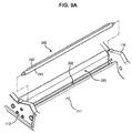
- FIG. 9A is a perspective view illustrating a partition and a return member provided in a developing device in accordance with another embodiment of the present general inventive concept
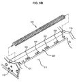
- FIG. 9B is a perspective view illustrating a partition and an agitating member provided in a developing device in accordance with still another embodiment of the present general inventive concept.
- an inlet 222 provided in a partition 220 may have form of a slit extending in a longitudinal direction of the partition 220 from a left sidewall 113 to a right sidewall 114 of a developing device.
- the developer delivered in the first developer receiving chamber 211 in the direction of a second developer receiving chamber by the developer delivery member, falls through the slitshaped inlet 222.
- the developing device of the present embodiment may further include a return member 240 arranged above the inlet 222 to return a part of the developer, having not been introduced into the inlet 222, in the direction of the developer delivery member.
- the return member 240 may include a rotating shaft 241, and a return blade 242 attached to an outer periphery of the rotating shaft 241.
- some developer having not been introduced into the inlet 222 is returned in the direction of the developer delivery member by the return member 240.
- a partition 320 is provided with a plurality of inlets 322 arranged in a longitudinal direction of the partition 320.
- a spiral agitating member 340 may be provided at the developer temporary storage portion 121. If the developer is delivered in the first developer receiving chamber 111 in the direction of the developer temporary storage portion 121 by the developer delivery member, the agitating member 340 agitates the developer, causing the developer to be uniformly distributed in a direction substantially transverse to the direction of the developer feed.
- the inlets may be altered in various manners.
- various shapes of other members such as the feed auger 140 of the first embodiment, the return member 240 of the second embodiment and the agitating member 340 of the third embodiment, may be provided above the inlets based on the number and shape of the inlets, thereby implementing operations to deliver the developer to the inlets, to level the developer, and/or to return the developer to the developer delivery member.
- the feed auger 140, return member 240, etc., described herein are given only by way of example, and various other shapes of members may also be installed.
- FIG. 10 is a perspective view illustrating an agitating member provided in a second developer receiving chamber in accordance with yet another embodiment of the present general inventive concept.
- An agitating member 350 in accordance with the present embodiment includes a spiral coil 351.
- the spiral coil 351 may be rotatably provided in a second developer receiving chamber 312 to prevent solidification of the developer fed into the second developer receiving chamber 312 and to level the developer.
- agitating members described herein are given by way of example, and may be altered into various shapes other than the above-described auger and spiral shapes, and various quantities of the agitating members may also be provided.
- the embodiments of the present general inventive concept provide a developing device having an improved developer delivery configuration.
Landscapes
- Physics & Mathematics (AREA)
- General Physics & Mathematics (AREA)
- Dry Development In Electrophotography (AREA)
Claims (10)
- Entwicklungsvorrichtung (40Y) zur Anbringung in einer vorgegebenen Position eines Abbildungsapparats (10), wobei die Entwicklungsvorrichtung umfasst:ein Zufuhrgerät (42Y) zum Zuführen einer Entwicklerflüssigkeit an ein Entwicklungsgerät;eine Entwicklerflüssigkeits-Aufnahmekammer (110), in der die Entwicklerflüssigkeit, die dem Entwicklungsgerät (40Y) zugeführt werden soll, empfangen wird,eine Trennwand (120), um die Entwicklerflüssigkeits-Aufnahmekammer (110) in eine erste Entwicklerflüssigkeits-Aufnahmekammer (111) und eine zweite Entwicklerflüssigkeits-Aufnahmekammer (112) zu unterteilen;einen Einlass (122), der in der Trennwand (120) geformt ist,eine erste Fördereinheit (140); undeine zweite Fördereinheit (150),wobei;wenn die Entwicklungsvorrichtung (40Y) in der vorgegebenen Position der Bilderzeugungsvorrichtung angebracht ist:der Einlass (122) so angeordnet ist, dass die Entwicklerflüssigkeit aus der ersten Entwicklerflüssigkeits-Aufnahmekammer (111) in die zweite Entwicklerflüssigkeits-Aufnahmekammer (112) unter Schwerkraft durch Durchfallen durch den Einlass (122) eingeführt werden kann;die erste Fördereinheit (140) in der ersten Entwicklerflüssigkeits-Aufnahmekammer an einer Position angebracht ist, die höher als der Einlass (122) liegt, und zum Zuführen der Entwicklerflüssigkeit durch den Einlass (122) zur zweiten Fördereinheit (150) angeordnet ist;die zweite Fördereinheit (150) in der zweiten Entwicklerflüssigkeits-Aufnahmekammer an einer Position angebracht ist, die tiefer als der Einlass (122) liegt, und zum Zuführen der Entwicklerflüssigkeit angeordnet ist, die durch den Einlass (122) von der ersten Fördereinheit (140) zum Zufuhrgerät (42Y), welches in der zweiten Entwicklerflüssigkeits-Aufnahmekammer (112) angebracht ist, empfangen wird, unddadurch gekennzeichnet ist, dassdie Entwicklungsvorrichtung ein Zufuhrelement (130) einschließt, das in der ersten Entwicklerflüssigkeits-Aufnahmekammer angeordnet ist; wobeiwenn die Entwicklungsvorrichtung (40Y) in der vorgegebenen Position der Bilderzeugungsvorrichtung angebracht ist:das Zufuhrelement (130) angeordnet ist, um die Entwicklerflüssigkeit aufwärts zur ersten Fördereinheit (140) zu befördern.
- Entwicklungsvorrichtung (40Y) nach Anspruch 1, wobei die Trennwand (120) einen ersten Trennwandabschnitt (121) zwischen der ersten Fördereinheit (140) und der zweiten Fördereinheit (150) und einen zweiten Trennwandabschnitt (123), der sich vom ersten Trennwandabschnitt im Wesentlichen nach unten erstreckt, einschließt.
- Entwicklungsvorrichtung (40Y) nach Anspruch 2, wobei der erste Trennwandabschnitt (121) einen unteren Teil der ersten Fördereinheit (140) im Wesentlichen umschließt.
- Entwicklungsvorrichtung (40Y) nach Anspruch 1, wobei der Einlass (122) an einem Ende der Trennwand (120) geformt ist.
- Entwicklungsvorrichtung (40Y) nach Anspruch 4, wobei die erste Fördereinheit (140) eine schraubenartige Förderschaufel (141) einschließt, um die Entwicklerflüssigkeit zum Einlass (122) zu befördern, und eine Radialförderschaufel (142) einschließt, um einen Teil der Entwicklerflüssigkeit, der nicht in den Einlass (122) eindringt, zurückzuführen.
- Entwicklungsvorrichtung (40Y) nach Anspruch 1, wobei sich der Einlass (122) der Trennwand (120) weiter unten als ein Spaltbereich zwischen dem Zufuhrgerät (42Y) und dem Entwicklungsgerät (43Y) befindet.
- Entwicklungsvorrichtung (40Y) nach Anspruch 1, die ferner ein Schutzelement (160) umfasst, um den Einlass (122) der Trennwand (120) selektiv zu schützen.
- Entwicklungsvorrichtung (40Y) nach Anspruch 2, wobei der zweite Trennwandabschnitt (123) die Rückführung der Entwicklerflüssigkeit, die von der ersten Fördereinheit (140) zur zweiten Fördereinheit (150) gefördert werden soll, begrenzt.
- Entwicklungsvorrichtung (40Y) nach einem der vorherigen Ansprüche, wobei eine untere Fläche (111a) der ersten Entwicklerflüssigkeits-Aufnahmekammer (111) einen Neigungswinkel im Bereich von ungefähr 2 Grad bis ungefähr 5 Grad als Reaktion darauf, dass die Entwicklungsvorrichtung (40Y) in der Bilderzeugungsvorrichtung (10) angebracht ist, aufweist.
- Entwicklungsvorrichtung (40Y) nach Anspruch 1,
wobei die zweite Fördereinheit (150) eine erste Umlaufschnecke (151) und eine zweite Umlaufschnecke (152) einschließt, und
die Entwicklungsvorrichtung (40Y) ferner eine umlaufende Wand (153) zwischen der ersten Umlaufschnecke (151) und der zweiten Umlaufschnecke (152) umfasst, die Verbindungslöcher (153a, 153b) aufweist, welche an gegenüberliegenden Seiten derselben geformt sind.
Applications Claiming Priority (1)
| Application Number | Priority Date | Filing Date | Title |
|---|---|---|---|
| KR1020080104511A KR101529490B1 (ko) | 2008-10-24 | 2008-10-24 | 화상형성장치의 현상기 |
Publications (2)
| Publication Number | Publication Date |
|---|---|
| EP2180377A1 EP2180377A1 (de) | 2010-04-28 |
| EP2180377B1 true EP2180377B1 (de) | 2013-12-18 |
Family
ID=41528597
Family Applications (1)
| Application Number | Title | Priority Date | Filing Date |
|---|---|---|---|
| EP09171348.7A Not-in-force EP2180377B1 (de) | 2008-10-24 | 2009-09-25 | Entwicklungsvorrichtung einer Bilderzeugungsvorrichtung |
Country Status (5)
| Country | Link |
|---|---|
| US (1) | US8139988B2 (de) |
| EP (1) | EP2180377B1 (de) |
| KR (1) | KR101529490B1 (de) |
| CN (1) | CN101727048B (de) |
| RU (1) | RU2429137C2 (de) |
Cited By (1)
| Publication number | Priority date | Publication date | Assignee | Title |
|---|---|---|---|---|
| WO2022225563A1 (en) * | 2021-04-21 | 2022-10-27 | Hewlett-Packard Development Company, L.P. | Toner cartridge with rotatable toner container and stationary agitator |
Families Citing this family (8)
| Publication number | Priority date | Publication date | Assignee | Title |
|---|---|---|---|---|
| KR20090104263A (ko) * | 2008-03-31 | 2009-10-06 | 삼성전자주식회사 | 화상형성장치 및 그 현상기 |
| KR101041084B1 (ko) * | 2009-09-01 | 2011-06-13 | 삼성전자주식회사 | 화상형성장치용 현상기 |
| JP5858939B2 (ja) * | 2013-01-28 | 2016-02-10 | 株式会社沖データ | 現像剤収容体、現像形成部、及び画像形成装置 |
| JP6485170B2 (ja) * | 2015-03-31 | 2019-03-20 | ブラザー工業株式会社 | 現像装置および画像形成装置 |
| JP7047541B2 (ja) * | 2018-03-30 | 2022-04-05 | ブラザー工業株式会社 | 現像カートリッジ |
| JP7479812B2 (ja) * | 2019-09-27 | 2024-05-09 | キヤノン株式会社 | 搬送ユニット、プロセスカートリッジおよび画像形成装置 |
| JP7703898B2 (ja) * | 2021-05-20 | 2025-07-08 | 富士フイルムビジネスイノベーション株式会社 | 現像装置、及び画像形成装置 |
| JP7632069B2 (ja) * | 2021-05-20 | 2025-02-19 | 富士フイルムビジネスイノベーション株式会社 | 現像装置及び画像形成装置 |
Family Cites Families (16)
| Publication number | Priority date | Publication date | Assignee | Title |
|---|---|---|---|---|
| US4647180A (en) * | 1984-10-25 | 1987-03-03 | Kabushiki Kaisha Toshiba | Developing device and electronic copying apparatus |
| JPH04340984A (ja) * | 1991-05-17 | 1992-11-27 | Konica Corp | 現像装置 |
| US5517286A (en) * | 1993-01-28 | 1996-05-14 | Canon Kabushiki Kaisha | Developing apparatus |
| JPH07253710A (ja) * | 1994-03-15 | 1995-10-03 | Mita Ind Co Ltd | トナーホッパ及びこれを含む現像装置 |
| JP3386624B2 (ja) * | 1995-02-16 | 2003-03-17 | 株式会社リコー | 現像装置およびそのトナーカートリッジ |
| JPH09288412A (ja) * | 1996-04-22 | 1997-11-04 | Minolta Co Ltd | 現像装置 |
| JPH10239970A (ja) | 1997-02-28 | 1998-09-11 | Fuji Xerox Co Ltd | 現像装置 |
| JP2001175082A (ja) | 1999-12-14 | 2001-06-29 | Kyocera Mita Corp | 回収トナーリサイクル式画像形成装置 |
| JP3499506B2 (ja) * | 2000-05-22 | 2004-02-23 | シャープ株式会社 | トナーカートリッジ |
| KR100503476B1 (ko) | 2002-08-14 | 2005-07-25 | 삼성전자주식회사 | 레이저 프린터의 토너/현상제 혼합롤러 및 현상장치 |
| US6671481B1 (en) * | 2002-10-29 | 2003-12-30 | Hewlett-Packard Development Company, L.P. | Endless belt dry toner agitator |
| JP4689327B2 (ja) * | 2004-06-16 | 2011-05-25 | キヤノン株式会社 | 画像形成装置 |
| KR100605169B1 (ko) | 2004-07-23 | 2006-07-28 | 삼성전자주식회사 | 화상형성장치 및 이를 이용한 현상제 공급방법 |
| JP2006267722A (ja) | 2005-03-24 | 2006-10-05 | Fuji Xerox Co Ltd | 現像装置及びこれを用いたプロセスカートリッジ並びに画像形成装置 |
| KR100644693B1 (ko) | 2005-04-22 | 2006-11-10 | 삼성전자주식회사 | 화상형성장치 |
| JP4646728B2 (ja) | 2005-07-28 | 2011-03-09 | 株式会社リコー | 現像装置及びこれを備えた画像形成装置 |
-
2008
- 2008-10-24 KR KR1020080104511A patent/KR101529490B1/ko not_active Expired - Fee Related
-
2009
- 2009-09-08 US US12/555,102 patent/US8139988B2/en active Active
- 2009-09-25 EP EP09171348.7A patent/EP2180377B1/de not_active Not-in-force
- 2009-10-08 RU RU2009137357/12A patent/RU2429137C2/ru active
- 2009-10-12 CN CN200910179528.9A patent/CN101727048B/zh active Active
Cited By (1)
| Publication number | Priority date | Publication date | Assignee | Title |
|---|---|---|---|---|
| WO2022225563A1 (en) * | 2021-04-21 | 2022-10-27 | Hewlett-Packard Development Company, L.P. | Toner cartridge with rotatable toner container and stationary agitator |
Also Published As
| Publication number | Publication date |
|---|---|
| RU2009137357A (ru) | 2011-04-20 |
| US20100104325A1 (en) | 2010-04-29 |
| CN101727048B (zh) | 2014-04-09 |
| RU2429137C2 (ru) | 2011-09-20 |
| KR20100045545A (ko) | 2010-05-04 |
| CN101727048A (zh) | 2010-06-09 |
| EP2180377A1 (de) | 2010-04-28 |
| US8139988B2 (en) | 2012-03-20 |
| KR101529490B1 (ko) | 2015-06-30 |
Similar Documents
| Publication | Publication Date | Title |
|---|---|---|
| EP2180377B1 (de) | Entwicklungsvorrichtung einer Bilderzeugungsvorrichtung | |
| US9354544B2 (en) | Developing device | |
| US7801466B2 (en) | Developing device and image forming apparatus | |
| KR101457760B1 (ko) | 현상제 수용 용기 및 이것이 장착된 화상 형성 장치 | |
| US20130011168A1 (en) | Developing unit of image forming apparatus | |
| JP5374939B2 (ja) | 現像装置及び画像形成装置 | |
| KR101457759B1 (ko) | 현상제 수용 용기 및 이것이 장착된 화상 형성 장치 | |
| US20110280623A1 (en) | Toner cartridge with waste toner storage and image forming apparatus having the same | |
| EP2290462B1 (de) | Entwicklungsvorrichtung für eine Bilderzeugungsvorrichtung | |
| JP2007011004A (ja) | 画像形成装置 | |
| US8032063B2 (en) | Developing device and image forming apparatus with the same | |
| JP5175909B2 (ja) | 現像装置および画像形成装置 | |
| JP2009300823A (ja) | 現像装置及び該現像装置を備えた画像形成装置 | |
| JP2010217225A (ja) | トナー攪拌装置、これを備えた現像装置、プロセスカートリッジ及び画像形成装置 | |
| US8229321B2 (en) | Image forming apparatus including grounded conductive member | |
| CN1506775A (zh) | 显影装置 | |
| JP2012047988A (ja) | 現像装置及びそれを備えた画像形成装置 | |
| JP7511811B2 (ja) | 粉体収容容器、トナー収容容器、現像装置、画像形成装置 | |
| JP2025116479A (ja) | 現像装置及びそれを備えた画像形成装置 | |
| JP2011141367A (ja) | 現像装置、プロセスカートリッジ及び画像形成装置 | |
| JP2012141455A (ja) | 現像装置および画像形成装置 | |
| JP2012032617A (ja) | 混合攪拌構造、現像装置、プロセスカートリッジ、および画像形成装置 | |
| JP2006301282A (ja) | 現像装置および画像形成装置 | |
| JPH0962076A (ja) | 画像形成装置 |
Legal Events
| Date | Code | Title | Description |
|---|---|---|---|
| PUAI | Public reference made under article 153(3) epc to a published international application that has entered the european phase |
Free format text: ORIGINAL CODE: 0009012 |
|
| AK | Designated contracting states |
Kind code of ref document: A1 Designated state(s): AT BE BG CH CY CZ DE DK EE ES FI FR GB GR HR HU IE IS IT LI LT LU LV MC MK MT NL NO PL PT RO SE SI SK SM TR |
|
| AX | Request for extension of the european patent |
Extension state: AL BA RS |
|
| 17P | Request for examination filed |
Effective date: 20100917 |
|
| 17Q | First examination report despatched |
Effective date: 20101008 |
|
| RAP1 | Party data changed (applicant data changed or rights of an application transferred) |
Owner name: SAMSUNG ELECTRONICS CO., LTD. |
|
| GRAP | Despatch of communication of intention to grant a patent |
Free format text: ORIGINAL CODE: EPIDOSNIGR1 |
|
| INTG | Intention to grant announced |
Effective date: 20130709 |
|
| GRAS | Grant fee paid |
Free format text: ORIGINAL CODE: EPIDOSNIGR3 |
|
| GRAA | (expected) grant |
Free format text: ORIGINAL CODE: 0009210 |
|
| AK | Designated contracting states |
Kind code of ref document: B1 Designated state(s): AT BE BG CH CY CZ DE DK EE ES FI FR GB GR HR HU IE IS IT LI LT LU LV MC MK MT NL NO PL PT RO SE SI SK SM TR |
|
| REG | Reference to a national code |
Ref country code: GB Ref legal event code: FG4D |
|
| REG | Reference to a national code |
Ref country code: CH Ref legal event code: EP |
|
| REG | Reference to a national code |
Ref country code: AT Ref legal event code: REF Ref document number: 645880 Country of ref document: AT Kind code of ref document: T Effective date: 20140115 |
|
| REG | Reference to a national code |
Ref country code: IE Ref legal event code: FG4D |
|
| REG | Reference to a national code |
Ref country code: DE Ref legal event code: R096 Ref document number: 602009020801 Country of ref document: DE Effective date: 20140213 |
|
| REG | Reference to a national code |
Ref country code: NL Ref legal event code: T3 |
|
| PG25 | Lapsed in a contracting state [announced via postgrant information from national office to epo] |
Ref country code: FI Free format text: LAPSE BECAUSE OF FAILURE TO SUBMIT A TRANSLATION OF THE DESCRIPTION OR TO PAY THE FEE WITHIN THE PRESCRIBED TIME-LIMIT Effective date: 20131218 Ref country code: HR Free format text: LAPSE BECAUSE OF FAILURE TO SUBMIT A TRANSLATION OF THE DESCRIPTION OR TO PAY THE FEE WITHIN THE PRESCRIBED TIME-LIMIT Effective date: 20131218 Ref country code: NO Free format text: LAPSE BECAUSE OF FAILURE TO SUBMIT A TRANSLATION OF THE DESCRIPTION OR TO PAY THE FEE WITHIN THE PRESCRIBED TIME-LIMIT Effective date: 20140318 Ref country code: LT Free format text: LAPSE BECAUSE OF FAILURE TO SUBMIT A TRANSLATION OF THE DESCRIPTION OR TO PAY THE FEE WITHIN THE PRESCRIBED TIME-LIMIT Effective date: 20131218 Ref country code: SE Free format text: LAPSE BECAUSE OF FAILURE TO SUBMIT A TRANSLATION OF THE DESCRIPTION OR TO PAY THE FEE WITHIN THE PRESCRIBED TIME-LIMIT Effective date: 20131218 |
|
| REG | Reference to a national code |
Ref country code: AT Ref legal event code: MK05 Ref document number: 645880 Country of ref document: AT Kind code of ref document: T Effective date: 20131218 |
|
| REG | Reference to a national code |
Ref country code: LT Ref legal event code: MG4D |
|
| PG25 | Lapsed in a contracting state [announced via postgrant information from national office to epo] |
Ref country code: LV Free format text: LAPSE BECAUSE OF FAILURE TO SUBMIT A TRANSLATION OF THE DESCRIPTION OR TO PAY THE FEE WITHIN THE PRESCRIBED TIME-LIMIT Effective date: 20131218 |
|
| PG25 | Lapsed in a contracting state [announced via postgrant information from national office to epo] |
Ref country code: BE Free format text: LAPSE BECAUSE OF FAILURE TO SUBMIT A TRANSLATION OF THE DESCRIPTION OR TO PAY THE FEE WITHIN THE PRESCRIBED TIME-LIMIT Effective date: 20131218 Ref country code: IS Free format text: LAPSE BECAUSE OF FAILURE TO SUBMIT A TRANSLATION OF THE DESCRIPTION OR TO PAY THE FEE WITHIN THE PRESCRIBED TIME-LIMIT Effective date: 20140418 Ref country code: EE Free format text: LAPSE BECAUSE OF FAILURE TO SUBMIT A TRANSLATION OF THE DESCRIPTION OR TO PAY THE FEE WITHIN THE PRESCRIBED TIME-LIMIT Effective date: 20131218 |
|
| PG25 | Lapsed in a contracting state [announced via postgrant information from national office to epo] |
Ref country code: SK Free format text: LAPSE BECAUSE OF FAILURE TO SUBMIT A TRANSLATION OF THE DESCRIPTION OR TO PAY THE FEE WITHIN THE PRESCRIBED TIME-LIMIT Effective date: 20131218 Ref country code: PL Free format text: LAPSE BECAUSE OF FAILURE TO SUBMIT A TRANSLATION OF THE DESCRIPTION OR TO PAY THE FEE WITHIN THE PRESCRIBED TIME-LIMIT Effective date: 20131218 Ref country code: AT Free format text: LAPSE BECAUSE OF FAILURE TO SUBMIT A TRANSLATION OF THE DESCRIPTION OR TO PAY THE FEE WITHIN THE PRESCRIBED TIME-LIMIT Effective date: 20131218 Ref country code: CY Free format text: LAPSE BECAUSE OF FAILURE TO SUBMIT A TRANSLATION OF THE DESCRIPTION OR TO PAY THE FEE WITHIN THE PRESCRIBED TIME-LIMIT Effective date: 20131218 Ref country code: CZ Free format text: LAPSE BECAUSE OF FAILURE TO SUBMIT A TRANSLATION OF THE DESCRIPTION OR TO PAY THE FEE WITHIN THE PRESCRIBED TIME-LIMIT Effective date: 20131218 Ref country code: RO Free format text: LAPSE BECAUSE OF FAILURE TO SUBMIT A TRANSLATION OF THE DESCRIPTION OR TO PAY THE FEE WITHIN THE PRESCRIBED TIME-LIMIT Effective date: 20131218 Ref country code: PT Free format text: LAPSE BECAUSE OF FAILURE TO SUBMIT A TRANSLATION OF THE DESCRIPTION OR TO PAY THE FEE WITHIN THE PRESCRIBED TIME-LIMIT Effective date: 20140418 Ref country code: ES Free format text: LAPSE BECAUSE OF FAILURE TO SUBMIT A TRANSLATION OF THE DESCRIPTION OR TO PAY THE FEE WITHIN THE PRESCRIBED TIME-LIMIT Effective date: 20131218 |
|
| REG | Reference to a national code |
Ref country code: DE Ref legal event code: R097 Ref document number: 602009020801 Country of ref document: DE |
|
| PLBE | No opposition filed within time limit |
Free format text: ORIGINAL CODE: 0009261 |
|
| STAA | Information on the status of an ep patent application or granted ep patent |
Free format text: STATUS: NO OPPOSITION FILED WITHIN TIME LIMIT |
|
| PG25 | Lapsed in a contracting state [announced via postgrant information from national office to epo] |
Ref country code: DK Free format text: LAPSE BECAUSE OF FAILURE TO SUBMIT A TRANSLATION OF THE DESCRIPTION OR TO PAY THE FEE WITHIN THE PRESCRIBED TIME-LIMIT Effective date: 20131218 |
|
| 26N | No opposition filed |
Effective date: 20140919 |
|
| REG | Reference to a national code |
Ref country code: DE Ref legal event code: R097 Ref document number: 602009020801 Country of ref document: DE Effective date: 20140919 |
|
| PG25 | Lapsed in a contracting state [announced via postgrant information from national office to epo] |
Ref country code: LU Free format text: LAPSE BECAUSE OF FAILURE TO SUBMIT A TRANSLATION OF THE DESCRIPTION OR TO PAY THE FEE WITHIN THE PRESCRIBED TIME-LIMIT Effective date: 20140925 Ref country code: MC Free format text: LAPSE BECAUSE OF FAILURE TO SUBMIT A TRANSLATION OF THE DESCRIPTION OR TO PAY THE FEE WITHIN THE PRESCRIBED TIME-LIMIT Effective date: 20131218 |
|
| REG | Reference to a national code |
Ref country code: CH Ref legal event code: PL |
|
| PG25 | Lapsed in a contracting state [announced via postgrant information from national office to epo] |
Ref country code: SI Free format text: LAPSE BECAUSE OF FAILURE TO SUBMIT A TRANSLATION OF THE DESCRIPTION OR TO PAY THE FEE WITHIN THE PRESCRIBED TIME-LIMIT Effective date: 20131218 |
|
| REG | Reference to a national code |
Ref country code: IE Ref legal event code: MM4A |
|
| PG25 | Lapsed in a contracting state [announced via postgrant information from national office to epo] |
Ref country code: LI Free format text: LAPSE BECAUSE OF NON-PAYMENT OF DUE FEES Effective date: 20140930 Ref country code: CH Free format text: LAPSE BECAUSE OF NON-PAYMENT OF DUE FEES Effective date: 20140930 |
|
| PG25 | Lapsed in a contracting state [announced via postgrant information from national office to epo] |
Ref country code: IE Free format text: LAPSE BECAUSE OF NON-PAYMENT OF DUE FEES Effective date: 20140925 |
|
| PG25 | Lapsed in a contracting state [announced via postgrant information from national office to epo] |
Ref country code: SM Free format text: LAPSE BECAUSE OF FAILURE TO SUBMIT A TRANSLATION OF THE DESCRIPTION OR TO PAY THE FEE WITHIN THE PRESCRIBED TIME-LIMIT Effective date: 20131218 |
|
| PG25 | Lapsed in a contracting state [announced via postgrant information from national office to epo] |
Ref country code: BG Free format text: LAPSE BECAUSE OF FAILURE TO SUBMIT A TRANSLATION OF THE DESCRIPTION OR TO PAY THE FEE WITHIN THE PRESCRIBED TIME-LIMIT Effective date: 20131218 Ref country code: GR Free format text: LAPSE BECAUSE OF FAILURE TO SUBMIT A TRANSLATION OF THE DESCRIPTION OR TO PAY THE FEE WITHIN THE PRESCRIBED TIME-LIMIT Effective date: 20140319 Ref country code: MT Free format text: LAPSE BECAUSE OF FAILURE TO SUBMIT A TRANSLATION OF THE DESCRIPTION OR TO PAY THE FEE WITHIN THE PRESCRIBED TIME-LIMIT Effective date: 20131218 |
|
| PG25 | Lapsed in a contracting state [announced via postgrant information from national office to epo] |
Ref country code: TR Free format text: LAPSE BECAUSE OF FAILURE TO SUBMIT A TRANSLATION OF THE DESCRIPTION OR TO PAY THE FEE WITHIN THE PRESCRIBED TIME-LIMIT Effective date: 20131218 Ref country code: HU Free format text: LAPSE BECAUSE OF FAILURE TO SUBMIT A TRANSLATION OF THE DESCRIPTION OR TO PAY THE FEE WITHIN THE PRESCRIBED TIME-LIMIT; INVALID AB INITIO Effective date: 20090925 |
|
| REG | Reference to a national code |
Ref country code: FR Ref legal event code: PLFP Year of fee payment: 8 |
|
| REG | Reference to a national code |
Ref country code: NL Ref legal event code: PD Owner name: S-PRINTING SOLUTION CO., LTD.; KO Free format text: DETAILS ASSIGNMENT: CHANGE OF OWNER(S), ASSIGNMENT; FORMER OWNER NAME: SAMSUNG ELECTRONICS CO., LTD. Effective date: 20170221 |
|
| REG | Reference to a national code |
Ref country code: GB Ref legal event code: 732E Free format text: REGISTERED BETWEEN 20170406 AND 20170412 |
|
| REG | Reference to a national code |
Ref country code: DE Ref legal event code: R081 Ref document number: 602009020801 Country of ref document: DE Owner name: HEWLETT-PACKARD DEVELOPMENT COMPANY, L.P., SPR, US Free format text: FORMER OWNER: SAMSUNG ELECTRONICS CO., LTD., SUWON-SI, GYEONGGI-DO, KR Ref country code: DE Ref legal event code: R081 Ref document number: 602009020801 Country of ref document: DE Owner name: HP PRINTING KOREA CO., LTD., SUWON-SI, KR Free format text: FORMER OWNER: SAMSUNG ELECTRONICS CO., LTD., SUWON-SI, GYEONGGI-DO, KR Ref country code: DE Ref legal event code: R081 Ref document number: 602009020801 Country of ref document: DE Owner name: S-PRINTING SOLUTION CO., LTD., SUWON-SI, KR Free format text: FORMER OWNER: SAMSUNG ELECTRONICS CO., LTD., SUWON-SI, GYEONGGI-DO, KR Ref country code: DE Ref legal event code: R082 Ref document number: 602009020801 Country of ref document: DE Representative=s name: SCHOPPE, ZIMMERMANN, STOECKELER, ZINKLER, SCHE, DE Ref country code: DE Ref legal event code: R082 Ref document number: 602009020801 Country of ref document: DE Representative=s name: GULDE & PARTNER PATENT- UND RECHTSANWALTSKANZL, DE |
|
| REG | Reference to a national code |
Ref country code: FR Ref legal event code: PLFP Year of fee payment: 9 |
|
| REG | Reference to a national code |
Ref country code: FR Ref legal event code: TP Owner name: S-PRINTING SOLUTION CO., LTD., KR Effective date: 20170912 |
|
| PG25 | Lapsed in a contracting state [announced via postgrant information from national office to epo] |
Ref country code: MK Free format text: LAPSE BECAUSE OF FAILURE TO SUBMIT A TRANSLATION OF THE DESCRIPTION OR TO PAY THE FEE WITHIN THE PRESCRIBED TIME-LIMIT Effective date: 20131218 |
|
| REG | Reference to a national code |
Ref country code: FR Ref legal event code: PLFP Year of fee payment: 10 |
|
| REG | Reference to a national code |
Ref country code: NL Ref legal event code: HC Owner name: HP PRINTING KOREA CO., LTD.; KR Free format text: DETAILS ASSIGNMENT: CHANGE OF OWNER(S), CHANGE OF OWNER(S) NAME; FORMER OWNER NAME: S-PRINTING SOLUTION CO., LTD. Effective date: 20180816 |
|
| REG | Reference to a national code |
Ref country code: DE Ref legal event code: R081 Ref document number: 602009020801 Country of ref document: DE Owner name: HEWLETT-PACKARD DEVELOPMENT COMPANY, L.P., SPR, US Free format text: FORMER OWNER: S-PRINTING SOLUTION CO., LTD., SUWON-SI, GYEONGGI-DO, KR Ref country code: DE Ref legal event code: R081 Ref document number: 602009020801 Country of ref document: DE Owner name: HP PRINTING KOREA CO., LTD., SUWON-SI, KR Free format text: FORMER OWNER: S-PRINTING SOLUTION CO., LTD., SUWON-SI, GYEONGGI-DO, KR Ref country code: DE Ref legal event code: R082 Ref document number: 602009020801 Country of ref document: DE Representative=s name: SCHOPPE, ZIMMERMANN, STOECKELER, ZINKLER, SCHE, DE Ref country code: DE Ref legal event code: R082 Ref document number: 602009020801 Country of ref document: DE |
|
| REG | Reference to a national code |
Ref country code: NL Ref legal event code: PD Owner name: HEWLETT-PACKARD DEVELOPMENT COMPANY, L.P.; US Free format text: DETAILS ASSIGNMENT: CHANGE OF OWNER(S), CHANGE OF LEGAL ENTITY; FORMER OWNER NAME: SAMSUNG ELECTRONICS CO., LTD. Effective date: 20191030 |
|
| REG | Reference to a national code |
Ref country code: DE Ref legal event code: R081 Ref document number: 602009020801 Country of ref document: DE Owner name: HEWLETT-PACKARD DEVELOPMENT COMPANY, L.P., SPR, US Free format text: FORMER OWNER: HP PRINTING KOREA CO., LTD., SUWON-SI, GYEONGGI-DO, KR |
|
| REG | Reference to a national code |
Ref country code: GB Ref legal event code: 732E Free format text: REGISTERED BETWEEN 20191212 AND 20191218 |
|
| REG | Reference to a national code |
Ref country code: DE Ref legal event code: R082 Ref document number: 602009020801 Country of ref document: DE Representative=s name: SCHOPPE, ZIMMERMANN, STOECKELER, ZINKLER, SCHE, DE |
|
| PGFP | Annual fee paid to national office [announced via postgrant information from national office to epo] |
Ref country code: NL Payment date: 20230822 Year of fee payment: 15 |
|
| PGFP | Annual fee paid to national office [announced via postgrant information from national office to epo] |
Ref country code: IT Payment date: 20230822 Year of fee payment: 15 Ref country code: GB Payment date: 20230823 Year of fee payment: 15 |
|
| PGFP | Annual fee paid to national office [announced via postgrant information from national office to epo] |
Ref country code: FR Payment date: 20230822 Year of fee payment: 15 Ref country code: DE Payment date: 20230822 Year of fee payment: 15 |
|
| REG | Reference to a national code |
Ref country code: DE Ref legal event code: R119 Ref document number: 602009020801 Country of ref document: DE |
|
| REG | Reference to a national code |
Ref country code: NL Ref legal event code: MM Effective date: 20241001 |
|
| GBPC | Gb: european patent ceased through non-payment of renewal fee |
Effective date: 20240925 |
|
| PG25 | Lapsed in a contracting state [announced via postgrant information from national office to epo] |
Ref country code: NL Free format text: LAPSE BECAUSE OF NON-PAYMENT OF DUE FEES Effective date: 20241001 |
|
| PG25 | Lapsed in a contracting state [announced via postgrant information from national office to epo] |
Ref country code: DE Free format text: LAPSE BECAUSE OF NON-PAYMENT OF DUE FEES Effective date: 20250401 |
|
| PG25 | Lapsed in a contracting state [announced via postgrant information from national office to epo] |
Ref country code: GB Free format text: LAPSE BECAUSE OF NON-PAYMENT OF DUE FEES Effective date: 20240925 |
|
| PG25 | Lapsed in a contracting state [announced via postgrant information from national office to epo] |
Ref country code: IT Free format text: LAPSE BECAUSE OF NON-PAYMENT OF DUE FEES Effective date: 20240925 |
|
| PG25 | Lapsed in a contracting state [announced via postgrant information from national office to epo] |
Ref country code: FR Free format text: LAPSE BECAUSE OF NON-PAYMENT OF DUE FEES Effective date: 20240930 |