EP2290462B1 - Entwicklungsvorrichtung für eine Bilderzeugungsvorrichtung - Google Patents
Entwicklungsvorrichtung für eine Bilderzeugungsvorrichtung Download PDFInfo
- Publication number
- EP2290462B1 EP2290462B1 EP10171841.9A EP10171841A EP2290462B1 EP 2290462 B1 EP2290462 B1 EP 2290462B1 EP 10171841 A EP10171841 A EP 10171841A EP 2290462 B1 EP2290462 B1 EP 2290462B1
- Authority
- EP
- European Patent Office
- Prior art keywords
- developer
- receiving chamber
- delivery
- developing device
- chamber
- Prior art date
- Legal status (The legal status is an assumption and is not a legal conclusion. Google has not performed a legal analysis and makes no representation as to the accuracy of the status listed.)
- Active
Links
Images



Classifications
-
- G—PHYSICS
- G03—PHOTOGRAPHY; CINEMATOGRAPHY; ANALOGOUS TECHNIQUES USING WAVES OTHER THAN OPTICAL WAVES; ELECTROGRAPHY; HOLOGRAPHY
- G03G—ELECTROGRAPHY; ELECTROPHOTOGRAPHY; MAGNETOGRAPHY
- G03G15/00—Apparatus for electrographic processes using a charge pattern
- G03G15/06—Apparatus for electrographic processes using a charge pattern for developing
- G03G15/08—Apparatus for electrographic processes using a charge pattern for developing using a solid developer, e.g. powder developer
- G03G15/0822—Arrangements for preparing, mixing, supplying or dispensing developer
- G03G15/0865—Arrangements for supplying new developer
-
- G—PHYSICS
- G03—PHOTOGRAPHY; CINEMATOGRAPHY; ANALOGOUS TECHNIQUES USING WAVES OTHER THAN OPTICAL WAVES; ELECTROGRAPHY; HOLOGRAPHY
- G03G—ELECTROGRAPHY; ELECTROPHOTOGRAPHY; MAGNETOGRAPHY
- G03G15/00—Apparatus for electrographic processes using a charge pattern
- G03G15/06—Apparatus for electrographic processes using a charge pattern for developing
-
- G—PHYSICS
- G03—PHOTOGRAPHY; CINEMATOGRAPHY; ANALOGOUS TECHNIQUES USING WAVES OTHER THAN OPTICAL WAVES; ELECTROGRAPHY; HOLOGRAPHY
- G03G—ELECTROGRAPHY; ELECTROPHOTOGRAPHY; MAGNETOGRAPHY
- G03G15/00—Apparatus for electrographic processes using a charge pattern
- G03G15/06—Apparatus for electrographic processes using a charge pattern for developing
- G03G15/08—Apparatus for electrographic processes using a charge pattern for developing using a solid developer, e.g. powder developer
- G03G15/0822—Arrangements for preparing, mixing, supplying or dispensing developer
- G03G15/0887—Arrangements for conveying and conditioning developer in the developing unit, e.g. agitating, removing impurities or humidity
- G03G15/0891—Arrangements for conveying and conditioning developer in the developing unit, e.g. agitating, removing impurities or humidity for conveying or circulating developer, e.g. augers
- G03G15/0893—Arrangements for conveying and conditioning developer in the developing unit, e.g. agitating, removing impurities or humidity for conveying or circulating developer, e.g. augers in a closed loop within the sump of the developing device
-
- G—PHYSICS
- G03—PHOTOGRAPHY; CINEMATOGRAPHY; ANALOGOUS TECHNIQUES USING WAVES OTHER THAN OPTICAL WAVES; ELECTROGRAPHY; HOLOGRAPHY
- G03G—ELECTROGRAPHY; ELECTROPHOTOGRAPHY; MAGNETOGRAPHY
- G03G15/00—Apparatus for electrographic processes using a charge pattern
- G03G15/06—Apparatus for electrographic processes using a charge pattern for developing
- G03G15/08—Apparatus for electrographic processes using a charge pattern for developing using a solid developer, e.g. powder developer
- G03G15/0896—Arrangements or disposition of the complete developer unit or parts thereof not provided for by groups G03G15/08 - G03G15/0894
-
- G—PHYSICS
- G03—PHOTOGRAPHY; CINEMATOGRAPHY; ANALOGOUS TECHNIQUES USING WAVES OTHER THAN OPTICAL WAVES; ELECTROGRAPHY; HOLOGRAPHY
- G03G—ELECTROGRAPHY; ELECTROPHOTOGRAPHY; MAGNETOGRAPHY
- G03G2215/00—Apparatus for electrophotographic processes
- G03G2215/08—Details of powder developing device not concerning the development directly
- G03G2215/0802—Arrangements for agitating or circulating developer material
-
- G—PHYSICS
- G03—PHOTOGRAPHY; CINEMATOGRAPHY; ANALOGOUS TECHNIQUES USING WAVES OTHER THAN OPTICAL WAVES; ELECTROGRAPHY; HOLOGRAPHY
- G03G—ELECTROGRAPHY; ELECTROPHOTOGRAPHY; MAGNETOGRAPHY
- G03G2215/00—Apparatus for electrophotographic processes
- G03G2215/08—Details of powder developing device not concerning the development directly
- G03G2215/0802—Arrangements for agitating or circulating developer material
- G03G2215/0816—Agitator type
- G03G2215/0827—Augers
-
- G—PHYSICS
- G03—PHOTOGRAPHY; CINEMATOGRAPHY; ANALOGOUS TECHNIQUES USING WAVES OTHER THAN OPTICAL WAVES; ELECTROGRAPHY; HOLOGRAPHY
- G03G—ELECTROGRAPHY; ELECTROPHOTOGRAPHY; MAGNETOGRAPHY
- G03G2215/00—Apparatus for electrophotographic processes
- G03G2215/08—Details of powder developing device not concerning the development directly
- G03G2215/0802—Arrangements for agitating or circulating developer material
- G03G2215/0836—Way of functioning of agitator means
- G03G2215/0838—Circulation of developer in a closed loop within the sump of the developing device
Definitions
- Embodiments of the present general inventive concept relate to a developing device usable with an electro-photographic image forming apparatus.
- image forming apparatuses are devised to form an image on a printing medium according to inputted image signals.
- Examples of image forming apparatuses include printers, copiers, facsimiles, and so-called multi-functional devices that combine some of the functionalities of the aforementioned devices.
- An electro-photographic image forming apparatus as a kind of the aforementioned image forming apparatuses includes a photosensitive body, a light scanning device, and a developing device.
- the light scanning device irradiates light to a surface of a photosensitive body that has been charged by a predetermined electric potential, thereby forming an electrostatic latent image on the surface of the photosensitive body.
- the developing device supplies developer to the electrostatic latent image, thereby forming a visible image.
- the visible image formed on the photosensitive body is directly transferred to the printing medium or is indirectly transferred to the printing medium by way of an intermediate transfer device. After being subjected to a fusing process, the printing medium, on which the image has been completely printed, is discharged out of the image forming apparatus.
- the developing device includes a developer receiving chamber to store developer, and a developer delivery device and a developing member arranged in the developer receiving chamber.
- the developer delivery device delivers the developer from the developer receiving chamber to the developing member.
- the developing member supplies the developer to the photosensitive body, enabling formation of a visible image.
- US 2009/0041508 A1 and US 2006/0204283 A1 both disclose developing units having a supply path, a recovery path and an agitation path. Openings are provided to allow communication between each path.
- JP H11 231625 discloses a developing device with a stirring screw, a feeding screw and partition disposed therebetween.
- JP2008310273 discloses a developing apparatus having a storage chamber and a supply chamber with an overfill preventing valve;
- JP2007140313 discloses a developing device with a partition to form a first toner chamber and a second toner chamber;
- JP2009186832 discloses a developing device having a movable shield member for shielding a toner inlet.
- Embodiments of the present general inventive concept provide a developing device usable with an image forming apparatus, which has an improved configuration to assure smooth flow of developer stored therein.
- Embodiments of the present general inventive concept can be achieved by providing a developing device usable with an image forming apparatus which includes a housing in which a developer receiving chamber is defined, a partition to divide the developer receiving chamber into a first developer receiving chamber and a second developer receiving chamber, and a first developer delivery member arranged in the second developer receiving chamber to deliver developer in a first direction, wherein the partition includes a developer supply port to allow the developer to be supplied from the first developer receiving chamber to the second developer receiving chamber during operation of the developing device, at least one opening to communicate the first developer receiving chamber and the second developer receiving chamber with each other, and a shield to block between the first developer receiving chamber and the second developer receiving chamber at an upstream position of the first direction so as to isolate the two developer receiving chambers from each other.
- the developing device may further include a second developer delivery member arranged in the second developer receiving chamber to deliver the developer in a second direction so as to transmit the developer to the first developer delivery member, and a developer delivery port to communicate downstream of the second developer delivery member with upstream of the first developer delivery member, and the shield may be formed at a position corresponding to the developer delivery port.
- a length of the shield may be longer than a length of the developer delivery port with respect to the first direction.
- the developing device may further include a barrier arranged at a position corresponding to an upstream end of the first developer delivery member between the first developer delivery member and the second developer delivery member.
- the partition may include a first section extending upwardly, preferably vertically, from the bottom of the housing, a second section extending, or preferably bent, from the first section to divide the developer receiving chamber into upper and lower parts, or vertically, and a third section extending upwardly, preferably vertically, from the second section, and the shield may be formed substantially at one end of the third section with respect to the first direction.
- the at least one opening may be formed in the third section.
- the at least one opening may include a plurality of openings arranged in the first direction.
- Embodiments of the present general inventive concept can also be achieved by providing a developing device usable with an image forming apparatus which includes a housing in which a developer receiving chamber is defined, a partition to divide the developer receiving chamber into a first developer receiving chamber and a second developer receiving chamber, a dividing wall to divide the second developer receiving chamber into a developer delivery chamber and a developing chamber, a developer supply port formed in the partition to allow the developer to be moved from the first developer receiving chamber to the developer delivery chamber, a developer delivery port formed in the dividing wall to allow the developer to be moved from the developer delivery chamber to the developing chamber, a first developer delivery member arranged in the developing chamber to deliver the developer having passed through the developer delivery port, a second developer delivery member arranged in the developer delivery chamber to deliver the developer toward the developer delivery port, at least one opening formed in the partition to communicate the first developer receiving chamber and the developing chamber with each other, and a shield formed at the partition at a position corresponding to the developer delivery port so as to isolate the first developer receiving chamber and the developing chamber from each other.
- a length of the shield may be longer than a length of the developer delivery port with respect to a developer delivery direction of the first developer delivery member.
- the at least one opening may be formed downstream of the shield with respect to a developer delivery direction of the first developer delivery member.
- the partition may include a first section arranged between the first developer receiving chamber and the developer delivery chamber, a second section extending from, or bent from, the first section toward the developing chamber and having a developer seat formed on an upper surface thereof, and a third section arranged between the first developer receiving chamber and the developing chamber, and the shield may be formed at, or substantially at, one end of the third section with respect to a developer delivery direction of the first developer delivery member.
- the first developer delivery member may include a sealing member coupled to an end thereof to prevent the developer from leaking out of the developing device, and the dividing wall may include a barrier arranged at a position corresponding to the sealing member between the first developer delivery member and the second developer delivery member.
- Embodiments of the present general inventive concept can also be achieved by providing a developing device usable with an image forming apparatus which includes a housing in which a developer receiving chamber is defined, a partition to divide the developer receiving chamber into a first developer receiving chamber and a second developer receiving chamber and having a developer seat and a developer supply port formed in the developer seat, a developer delivery belt arranged in the first developer receiving chamber to deliver developer to the developer seat, a developer supply member arranged on the developer seat to deliver the developer to the developer supply port, a first developer delivery member and a second developer delivery member rotatably supported in the housing to deliver the developer in different directions within the second developer receiving chamber, a dividing wall to separate the first developer delivery member and the second developer delivery member from each other, the dividing wall having a developer delivery port formed substantially at one end thereof to allow passage of the developer, at least one opening formed in the partition to communicate the first developer receiving chamber and the developing chamber with each other, and a shield formed at the partition at a position corresponding to the developer delivery port so as to isolate the first
- the shield may be arranged above the developer seat.
- the at least one opening may be arranged above the developer seat.
- the first developer delivery member may include a delivery blade formed in an axial direction thereof, and a sealing member coupled to an end thereof to prevent the developer from leaking out of the developing device, and the dividing wall may include a barrier arranged at a position corresponding to the sealing member between the first developer delivery member and the second developer delivery member.
- the developing device may further include a photosensitive body, a developing roller arranged in the second developer receiving chamber to supply the developer to the photosensitive body, and a supply roller arranged in the second developer receiving chamber to supply the developer to the developing roller, and the first developer delivery member may be arranged between the supply roller and the second developer delivery member.
- Embodiments of the present general inventive concept can also be achieved by providing a developing device usable with an image forming apparatus, the developing device comprising: a housing including a developer receiving chamber therein, the developer receiving chamber being divided into a first part and a second part; a partition to divide the developer receiving chamber into the first and second parts, the partition including: a developer supply port to allow developer to be supplied from the first part to the second part during operation thereof, and a plurality of openings to communicate the first part with the second part; a first developer delivery member disposed in the second part of and including a delivery mechanism disposed along a predetermined portion thereof to deliver developer in a first direction; a second developer delivery member disposed in the second part and including a delivery mechanism disposed along a predetermined portion thereof to deliver developer in an opposite direction than the first direction; and a dividing wall disposed between the first and second developer delivery members, the dividing wall comprising: a developer delivery port to deliver developer from the first developer delivery member to the second developer delivery member and disposed at a predetermined position
- the first developer delivery member and delivery mechanism may comprise a shaft including a sealing member at an end thereof and a blade extending rotationally from the sealing member along the length of the shaft such that the developer delivery port is disposed to face the blade adjacent to the sealing member.
- the developer circulation port may be disposed on the dividing wall farthest from the sealing member of the first developer delivery member.
- FIG. 1 is a view illustrating a configuration of an image forming apparatus having a developing device according to an embodiment of the present general inventive concept.
- the image forming apparatus 1 includes a body 10, a printing medium supply unit 20, a light scanning unit 30, a developing unit 40, a transfer unit 50, a fusing unit 60, and a printing medium discharge unit 70.
- the body 10 defines an external appearance of the image forming apparatus 1 and supports a variety of elements mounted therein.
- the printing medium supply unit 20 includes a cassette 21 in which printing media S is stored, a pickup roller 22 to pick up the printing media S stored in the cassette 21 sheet by sheet, and delivery rollers 23 to deliver the picked-up printing medium toward the transfer unit 50.
- the light scanning unit 30 includes four light scanning devices 30Y, 30M, 30C, and 30K to irradiate light, corresponding to Yellow, Magenta, Cyan, and Black image information according to printing signals, to respective photosensitive bodies 44Y, 44M, 44C, and 44K of developing devices 40Y, 40M, 40C, and 40K that will be described hereinafter.
- electrostatic latent images are formed on the respective photosensitive bodies 44Y, 44M, 44C and 44K.
- the developing unit 40 includes the four developing devices 40Y, 40M, 40C and 40K, in which different colors of developers, for example, yellow (Y), magenta (M), cyan (C) and black (K) developers are received respectively.
- yellow (Y) yellow
- M magenta
- C cyan
- K black
- the developing device 40Y in which a yellow developer (Y) is received will be described hereinafter by way of example, it will be appreciated that the following description is applicable to the other three developing devices 40M, 40C and 40K in which magenta (M), cyan (C) and black (K) developers are received respectively although this is not specially mentioned.
- the developing device 40Y includes a housing 41Y, a developer receiving chamber 100, a supply roller 42Y, a developing roller 43Y, and the photosensitive body 44Y
- the developer receiving chamber 100 is defined in the interior of the housing 41Y and stores the developer to be supplied to the photosensitive body 44Y.
- the supply roller 42Y is mounted in the housing 41Y and supplies the developer stored in the developer receiving chamber 100 to the developing roller 43Y.
- the developing roller 43Y attaches the developer to a surface of the photosensitive body 44Y on which an electrostatic latent image has been formed by the light scanning device 30Y, so as to form a visible image.
- the photosensitive body 44Y is rotatably coupled to a tip end of the housing 41Y and receives the developer from the developing roller 43Y
- the photosensitive body 44Y may be separated from the developing device 40Y
- Reference numeral 45Y represents a charging roller to charge the photosensitive body 44Y with a predetermined electric potential before the light scanning device 30 irradiates light to the photosensitive body 44Y
- the transfer unit 50 serves to transfer the visible image formed on the photosensitive body 44Y to the printing medium.
- the transfer unit 50 includes a printing medium delivery belt 51, a driving roller 52, a driven roller 53, and a plurality of transfer rollers 54.
- the printing medium delivery belt 51 delivers the printing medium supplied from the printing medium supply unit 20 to each of the plurality of photosensitive bodies 44Y, 44M, 44C, and 44K.
- the driving roller 52 and the driven roller 53 are arranged inside the printing medium delivery belt 51 at opposite ends thereof, and act to rotate the printing medium delivery belt 51 in an endless orbit.
- the plurality of transfer rollers 54 is arranged opposite the respective photosensitive bodies 44Y, 44M, 44C and 44K with the printing medium delivery belt 51 interposed therebetween, so that the visible image formed on each of the photosensitive bodies 44Y, 44M, 44C and 44K is transferred to the printing medium delivered by the printing medium delivery belt 51.
- the fusing unit 60 includes a heating roller 61 having a heating source, and a press roller 62 arranged opposite the heating roller 61.
- a heating roller 61 having a heating source
- a press roller 62 arranged opposite the heating roller 61.
- the printing medium discharge unit 70 includes a paper discharge roller 71 and a paper backup roller 72 and discharges the printing medium, having passed through the fusing unit 60, out of the body 10.
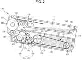
- FIG. 2 is a sectional view illustrating the developing device according to the embodiment of the present general inventive concept
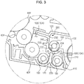
- FIG. 3 is a partial enlarged view of FIG. 2
- FIG. 4 is a perspective view illustrating some constituent elements shown in FIG. 2 .
- the housing 41Y includes a base frame 110, a cover 120, an upper frame 130, and an upper cover 140.
- the base frame 110 supports a variety of elements received therein.
- the cover 120 is configured to cover a top of the base frame 110 and is coupled with the base frame 110 to define the developer receiving chamber 100 for storage of the developer together.
- the upper frame 130 and the upper cover 140 are arranged above the cover 120 and define a waste developer receiving chamber 132 for storage of waste developer collected from the photosensitive body 44Y.
- the upper frame 130 is provided with a cleaning member 134.
- the cleaning member 134 scrapes away the developer remaining on the surface of the photosensitive member 44Y.
- the waste developer removed by the cleaning member 134 is delivered by a waste developer delivery member 136 and is stored in the waste developer receiving chamber 132.
- the waste developer delivery member 136 is arranged above the cleaning member 134.
- the waste developer delivery member 136 may have a plate shape and may be formed of a plastic molded product or a film having high restoration elasticity. Providing the plate-shaped waste developer delivery member 136 may reduce a height of the developing device 40Y, enabling efficient delivery of waste developer even if a height of the waste developer receiving chamber 132 is reduced.
- the developer receiving chamber 100 is divided into a first developer receiving chamber 102 and a second developer receiving chamber 104 by a partition 200.
- the first developer receiving chamber 102 stores the developer therein
- the second developer receiving chamber 104 accommodates a variety of constituent elements required to supply the developer to the photosensitive body 44Y, such as the supply roller 42Y, and the developing roller 43Y, etc.
- the partition 200 is arranged between the first developer receiving chamber 102 and the second developer receiving chamber 104.
- the partition 200 is configured to prevent all the developer from being moved from the first developer receiving chamber 102 to the second developer receiving chamber 104, so as to reduce stress applied to the developer when a great amount of developer is concentrated into the second developer receiving chamber 104.
- the partition 200 provides the benefit of preventing too much weight being applied to developer resting in the second developer receiving chamber 104.
- the partition 200 also serves to prevent developer, which has been deteriorated by a temperature and pressure near the supply roller 42Y and the developing roller 43Y, from flowing backward toward the first developer receiving chamber 102, and to enable successive consumption of the developer from near the developing roller 43Y
- the partition 200 may include a first section 210, a second section 220, and a third section 230.
- the first section 210 extends vertically, or upwards, from the bottom of the base frame 110.
- the second section 220 projects from, or is bent from, an upper end of the first section 210 toward the second developer receiving chamber 104 and defines a developer seat 222 on an upper surface thereof.
- the third section 230 extends vertically, or upwards, from the second section 220. An upper end of the third section 230 projects, or is bent, toward the second developer receiving chamber 104 so as to come into close contact with the cover 120.
- a belt device 150 is arranged in the first developer receiving chamber 102 (see FIG. 2 ).
- the belt device 150 serves to deliver a part of the developer stored in the first developer receiving chamber 102 toward the developer seat 222 of the partition 200.
- the belt device 150 also serves to agitate the developer inside the first developer receiving chamber 102.
- the belt device 150 includes a first rotator 152, a second rotator 154, and a developer delivery belt 156.
- the first rotator 152 and the second rotator 154 rotatably support the developer delivery belt 156.
- the developer delivery belt 156 rotates around the first rotator 152 and the second rotator 154 and delivers the developer stored in the first developer receiving chamber 102 to the developer seat 222 of the partition 200.
- the first rotator 152 is positioned in the first developer receiving chamber 102 at a position adjacent to the partition 200.
- the second rotator 154 is arranged at an opposite side of the base frame 110 with respect to the first rotator 152 and with a predetermined distance therebetween.
- the first rotator 152 rotates upon receiving power from a motor (not shown) mounted in the body 10 and supports one side of an inner surface of the developer delivery belt 156 to transmit rotation power to the developer delivery belt 156.
- the second rotator 154 supports the other side of the inner surface of the developer delivery belt 156 and is rotated together with the developer delivery belt 156.
- the first rotator 152 and the second rotator 154 may include a spiral blade structure to agitate the developer stored in the first developer receiving chamber 102.
- the developer delivery belt 156 may take the form of a film having a thickness of 2 mm or less and may be made of polyethylene terephthalate (PET), polycarbonate (PC), etc.
- PET polyethylene terephthalate
- PC polycarbonate
- Using the belt for delivery of developer may simplify a developer delivery configuration even if the height of the developing device is reduced for a reduced size of the image forming apparatus and also, may reduce stress applied to the developer during delivery of the developer.
- the first developer receiving chamber 102 and the second developer receiving chamber 104 communicate with each other through a developer supply port 224 perforated in the partition 200.
- the developer stored in the first developer receiving chamber 102 is delivered into the second developer receiving chamber 104 through the developer supply port 224 during operation of the developing device 40Y.
- the developer supply port 224 of the partition 200 may be formed at one end of the developer seat 222.
- a developer supply member 160 may be arranged on the partition 200 to deliver the developer present on the developer seat 222 toward the developer supply port 224.
- the developer supply member 160 may take the form of an auger.
- the developer supply member 160 may include a delivery blade 162 extending along a length thereof to generate an axial delivery force, and a return blade 164 provided at an end of the developer supply member 160 at a position corresponding to the developer supply port 224.
- the developer supplied to the developer seat 222 by the belt device 150 is delivered to one side of the partition 200 by the developer supply member 160 and thereafter, falls into the second developer receiving chamber 104 through the developer supply port 224.
- the developer After a sufficient amount of developer is supplied into the second developer receiving chamber 104 by the developer supply member 160, the developer is not introduced through the developer supply port 224 any more, and is returned into the first developer receiving chamber 102 by the return blade 164 of the developer supply member 160.
- FIG. 5 is a perspective view illustrating some constituent elements of the developing device according to the embodiment of the present general inventive concept
- FIG. 6 is a partial enlarged view of FIG. 5 .
- the second developer receiving chamber 104 is divided into a developer delivery chamber 106 and a developing chamber 108 by a dividing wall 170.
- the developer delivery chamber 106 is located below the second section 220 of the partition 200, and communicates with the first developer receiving chamber 102 through the developer supply port 224.
- the third section 230 of the partition 200 is arranged between the first developer receiving chamber 102 and the developing chamber 108.
- a developer delivery port 172 is perforated in one end of the dividing wall 170 to allow the developer to be moved from the developer delivery chamber 106 to the developing chamber 108.
- a developer circulation port 174 is perforated in the other end of the dividing wall 170 to allow the developer to be returned from the developing chamber 108 to the developer delivery chamber 106.
- the developing roller 43Y, the supply roller 42Y, and a first developer delivery member 180 are arranged in the developing chamber 108, and a second developer delivery member 190 is arranged in the developer delivery chamber 106.
- the first developer delivery member 180 and the second developer delivery member 190 are rotatably supported at opposite side surfaces of the base frame 110.
- the first developer delivery member 180 delivers the developer in a first direction (designated by the arrows X1), thereby allowing the developer to be supplied to the developing roller 43Y by way of the supply roller 42Y.
- the developer supplied to the developing roller 43Y defines a layer of developer and the developer layer is leveled by a regulator (128, see FIG. 2 ).
- a regulator see FIG. 2
- a part of the developer which reaches the developer circulation port 174 rather than being supplied to the photosensitive body 44, is returned into the developer delivery chamber 106 through the developer circulation port 174.
- the first developer delivery member 180 may include a delivery shaft 182 and a delivery blade 184 spirally formed on the delivery shaft 182 in an axial direction of the delivery shaft 182.
- a sealing member 186 may be coupled to an end section of the delivery shaft 182 at a position adjacent to the developer delivery port 172. The sealing member 186 prevents the developer from leaking out of the developing device 40Y through a penetration hole of the delivery shaft 182 perforated in the base frame 110.
- the developer supplied into the developer delivery chamber 106 through the developer supply port 224 is delivered toward the developer delivery port 172 in a second direction (designated by the arrows X2) by the second developer delivery member 190.
- the second developer delivery member 190 may include a delivery shaft 192 and a delivery blade 194 spirally formed on the delivery shaft 192 in an axial direction of the delivery shaft 192.
- FIGS. 3 to 5 illustrate the developer supply member 160, the first developer delivery member 180, the second developer delivery member 190, the supply roller 42Y and the developing roller 43Y, all of which constitute a mechanism to supply the developer toward the photosensitive body 44Y, by way of example, other developer supply mechanisms may also be used.
- the developer supply member 160 and the developer delivery members 180 and 190 in the form of augers shown in FIG. 2 may be replaced by other shapes and types of delivery members.
- the partition 200 includes openings 240 to communicate the first developer receiving chamber 102 and the second developer receiving chamber 104 with each other.
- the opening 240 may prevent deterioration in fluidity of the developer despite an increased pressure in the developing chamber 108, thereby preventing deterioration in print quality.
- the pressure in the developing chamber 108 increases, causing deterioration in fluidity of the developer.
- the deteriorated fluidity of the developer prevents efficient frictional charge during delivery of the developer, deteriorating electric-charge characteristics of the developer and causing print failure due to the developer being attached to an unexpected region other than the intended light scanning region of the photosensitive body 44Y
- the openings 240 of the partition 200 prevent the pressure increase of the developing chamber 108, preventing print failure due to the increased pressure of the developing chamber 108.
- the openings 240 may be formed in the third section 230 of the partition 200 and may be arranged in the first direction as a developer delivery direction of the first developer delivery member 180.
- an anti-backflow member 250 may be provided below the openings 240.
- the anti-backflow member 250 protrudes from the third section 230 of the partition 200 into the developing chamber 108, thereby preventing the developer from flowing backward from the developing chamber 108 into the first developer receiving chamber 102 through the openings 240.
- FIGS. 4 and 5 illustrate an example wherein the plurality of openings 240 is formed in the partition 200 in the first direction, alternatively, only one opening may be formed, or a plurality of slits may be arranged vertically.
- the partition 200 includes a shield 260, which blocks between the first developer receiving chamber 102 and the second developer receiving chamber 104 at an upstream position of the first direction X1, i.e., of the developer delivery direction of the first developer delivery member 180, so as to isolate the two developer receiving chambers 102 and 104 from each other.
- the shield 260 may be formed in one end of the third section 230 of the partition 200.
- the shield 260 prevents the developer of the first developer receiving chamber 102 from flowing upstream of the first developer delivery member 180 without passing through the developer supply member 160 and the second developer delivery member 190. If the developer of the first developer receiving chamber 102 flows upstream of the first developer delivery member 180 without successively passing through the developer supply member 160 and the second developer delivery member 190, insufficiently frictionally charged developer may be supplied to the developing roller 43Y, causing print failure. However, providing the partition 200 with the shield 260 at the upstream position of the first direction X1 can prevent the insufficiently frictionally charged developer of the first developer receiving chamber 102 from directly flowing into the first developer delivery member 180, thereby preventing print failure.
- the shield 260 may be formed at a position corresponding to the developer delivery port 172 of the dividing wall 170.
- the shield 260 serves as a guide to efficiently deliver the developer in the first direction X1 when the first developer delivery member 180 delivers the developer having passed through the developer delivery port 172.
- the first developer receiving chamber 102 and the developing chamber 108 communicate with each other near the developer delivery port 172 where a larger amount of the developer is concentrated than other regions, the first developer receiving chamber 102 absorbs delivery pressure of the first developer delivery member 180, causing a weak delivery force in the first direction X1 and deepening concentration of the developer near the developer delivery port 172.
- the developer near the developer delivery port 172 may be efficiently delivered in the first direction X1.
- a length L1 of the shield 260 may be longer than a length L2 of the developer delivery port 172 with respect to the first direction X1.
- the dividing wall 170 may include a barrier 176 arranged at a position corresponding to the sealing member 186 of the first developer delivery member 180.
- a portion of the first developer delivery member 180 where the sealing member 186 is mounted has a lower delivery force than the remaining portion of the first developer delivery member 180 where the delivery blade 184 is formed.
- the barrier 176 prevents the developer of the developer delivery chamber 106 from being directly supplied to the sealing member 186 of the first developer delivery member 180, thereby serving to prevent concentration of the developer at the sealing member 186. Moreover, even if the developer reaches near the sealing member 186, the barrier 176 serves to guide smooth movement of the developer in the first direction X1.
- the above described embodiment exemplifies that a single developer delivery member 180 is arranged in the developing chamber 108 and the shield 260 is provided at one side of the partition 200, two or more developer delivery members may be arranged in the developing chamber 108 and two shields 260 may provided at opposite sides of the partition 200.
Landscapes
- Physics & Mathematics (AREA)
- General Physics & Mathematics (AREA)
- Dry Development In Electrophotography (AREA)
Claims (5)
- Entwicklungsvorrichtung (40Y), die mit einer Bilderzeugungsvorrichtung (1) verwendbar ist, wobei die Entwicklungsvorrichtung Folgendes umfasst:ein Gehäuse (41Y), in dem eine Entwicklerflüssigkeitsaufnahmekammer (100) definiert ist;eine Trennwand (200), um die Entwicklerflüssigkeitsaufnahmekammer (100) in eine erste Entwicklerflüssigkeitsaufnahmekammer (102) und in eine zweite Entwicklerflüssigkeitsaufnahmekammer (104) zu teilen; undein erstes Entwicklerflüssigkeitszuführelement (180), das in der zweiten Entwicklerflüssigkeitsaufnahmekammer (104) angeordnet ist, um Entwicklerflüssigkeit in einer ersten Richtung (X1) zuzuführen,wobei die Trennwand (200) einen Entwicklerflüssigkeitslieferanschluss (224), um zu ermöglichen, dass die Entwicklerflüssigkeit von der ersten Entwicklerflüssigkeitsaufnahmekammer (102) zu der zweiten Entwicklerflüssigkeitsaufnahmekammer (104) während eines Betriebs der Entwicklungsvorrichtung (40Y) geliefert wird, und wenigstens eine Öffnung (240) beinhaltet, um die erste Entwicklerflüssigkeitsaufnahmekammer (102) und die zweite Entwicklerflüssigkeitsaufnahmekammer (104) miteinander zu verbinden,wobei die Trennwand (200) ferner ein Schild (260) beinhaltet, um einen Entwicklerflüssigkeitsfluss zwischen der ersten Entwicklerflüssigkeitsaufnahmekammer (102) und der zweiten Entwicklerflüssigkeitsaufnahmekammer (104) an einer stromaufwärtigen Position der ersten Richtung (X1) zu blockieren, um die zwei Entwicklerflüssigkeitsaufnahmekammern (102, 104) voneinander zu isolieren,wobei die Trennwand (200) Folgendes beinhaltet: einen ersten Bereich (210), der sich von dem Boden des Gehäuses nach oben hin erstreckt, einen zweiten Bereich (220), der von dem ersten Bereich (210) hervorsteht, um die Entwicklerflüssigkeitsaufnahmekammer (100) senkrecht zu trennen, und einen dritten Bereich (230), der sich von dem zweiten Bereich (220) nach oben hin erstreckt; unddadurch gekennzeichnet, dass die wenigstens eine Öffnung (240) in dem dritten Bereich (230) ausgebildet ist und das Schild (260) an einem Ende des dritten Bereichs (230) bezogen auf die erste Richtung (X1) ausgebildet ist.
- Entwicklungsvorrichtung nach Anspruch 1, ferner umfassend:ein zweites Entwicklerflüssigkeitszuführelement (190), das in der zweiten Entwicklerflüssigkeitsaufnahmekammer (104) angeordnet ist, um die Entwicklerflüssigkeit in einer zweiten Richtung (X2) zuzuführen, um die Entwicklerflüssigkeit an das erste Entwicklerflüssigkeitszuführelement (180) zu übertragen; undeinen Entwicklerflüssigkeitszuführanschluss (172), um stromabwärts des zweiten Entwicklerflüssigkeitszuführelementes (190) mit stromaufwärts des ersten Entwicklerzuführflüssigkeitselement (180) zu verbinden,wobei das Schild (260) an einer Position ausgebildet ist, die dem Entwicklerflüssigkeitszuführanschluss (172) entspricht.
- Entwicklungsvorrichtung nach Anspruch 2, wobei eine Länge (L1) des Schilds (260) länger ist als eine Länge (L2) des Entwicklerflüssigkeitszuführanschlusses (172) bezogen auf die erste Richtung (X1).
- Entwicklungsvorrichtung nach Anspruch 2 oder 3, ferner umfassend eine Wand (176), die an einer Position, die einem stromaufwärtigen Ende, bezogen auf die erste Richtung (X1), des ersten Entwicklerflüssigkeitszuführelementes (180) entspricht, zwischen dem ersten Entwicklerflüssigkeitszuführelement (180) und dem zweiten Entwicklerflüssigkeitszuführelement (190) angeordnet ist.
- Entwicklungsvorrichtung nach einem der vorhergehenden Ansprüche, wobei die wenigstens eine Öffnung (240) mehrere Öffnungen beinhaltet, die in der ersten Richtung (X1) angeordnet sind.
Applications Claiming Priority (1)
| Application Number | Priority Date | Filing Date | Title |
|---|---|---|---|
| KR1020090081744A KR101041084B1 (ko) | 2009-09-01 | 2009-09-01 | 화상형성장치용 현상기 |
Publications (3)
| Publication Number | Publication Date |
|---|---|
| EP2290462A2 EP2290462A2 (de) | 2011-03-02 |
| EP2290462A3 EP2290462A3 (de) | 2014-10-22 |
| EP2290462B1 true EP2290462B1 (de) | 2018-10-03 |
Family
ID=43334461
Family Applications (1)
| Application Number | Title | Priority Date | Filing Date |
|---|---|---|---|
| EP10171841.9A Active EP2290462B1 (de) | 2009-09-01 | 2010-08-04 | Entwicklungsvorrichtung für eine Bilderzeugungsvorrichtung |
Country Status (4)
| Country | Link |
|---|---|
| US (2) | US8437666B2 (de) |
| EP (1) | EP2290462B1 (de) |
| KR (1) | KR101041084B1 (de) |
| CN (1) | CN201796230U (de) |
Families Citing this family (6)
| Publication number | Priority date | Publication date | Assignee | Title |
|---|---|---|---|---|
| JP2014066844A (ja) | 2012-09-26 | 2014-04-17 | Brother Ind Ltd | 現像器 |
| JP6390602B2 (ja) * | 2015-12-17 | 2018-09-19 | 京セラドキュメントソリューションズ株式会社 | 現像装置及びそれを備えた画像形成装置 |
| JP6699212B2 (ja) * | 2016-02-10 | 2020-05-27 | 富士ゼロックス株式会社 | 現像装置および画像形成装置 |
| JP6919209B2 (ja) * | 2017-01-30 | 2021-08-18 | コニカミノルタ株式会社 | 現像装置、および画像形成装置 |
| JP6945801B2 (ja) * | 2017-06-15 | 2021-10-06 | 株式会社リコー | 現像装置、プロセスカートリッジ、及び、画像形成装置 |
| CN212846362U (zh) * | 2019-07-12 | 2021-03-30 | 纳思达股份有限公司 | 一种显影盒 |
Citations (3)
| Publication number | Priority date | Publication date | Assignee | Title |
|---|---|---|---|---|
| JP2007140313A (ja) * | 2005-11-22 | 2007-06-07 | Kyocera Mita Corp | 現像装置 |
| JP2008310273A (ja) * | 2007-06-18 | 2008-12-25 | Kyocera Mita Corp | 現像装置 |
| JP2009186832A (ja) * | 2008-02-07 | 2009-08-20 | Fuji Xerox Co Ltd | 現像装置及び画像形成装置 |
Family Cites Families (11)
| Publication number | Priority date | Publication date | Assignee | Title |
|---|---|---|---|---|
| JPH11231625A (ja) * | 1998-02-12 | 1999-08-27 | Minolta Co Ltd | 現像装置 |
| JP2006251440A (ja) * | 2005-03-11 | 2006-09-21 | Ricoh Co Ltd | 現像装置、プロセスカートリッジ、及び画像形成装置 |
| JP2006267722A (ja) * | 2005-03-24 | 2006-10-05 | Fuji Xerox Co Ltd | 現像装置及びこれを用いたプロセスカートリッジ並びに画像形成装置 |
| JP2006276490A (ja) * | 2005-03-29 | 2006-10-12 | Fuji Xerox Co Ltd | 現像装置及びこれを用いたプロセスカートリッジ並びに画像形成装置 |
| JP2007086392A (ja) * | 2005-09-22 | 2007-04-05 | Fuji Xerox Co Ltd | 画像形成装置 |
| JP2007298908A (ja) * | 2006-05-08 | 2007-11-15 | Fuji Xerox Co Ltd | プロセスカートリッジ、画像形成装置及びプロセスカートリッジの組立て方法 |
| JP2007304281A (ja) * | 2006-05-10 | 2007-11-22 | Fuji Xerox Co Ltd | 粉体供給器、粉体供給器への粉体充填方法、及び画像形成装置 |
| JP4479693B2 (ja) * | 2006-06-02 | 2010-06-09 | 富士ゼロックス株式会社 | 粉体供給器、粉体供給器の製造方法、及び粉体供給器の再生方法 |
| JP4924005B2 (ja) * | 2006-12-18 | 2012-04-25 | 富士ゼロックス株式会社 | 現像剤搬送装置、現像装置、可視像形成装置および画像形成装置 |
| US7991330B2 (en) * | 2007-08-07 | 2011-08-02 | Ricoh Company, Ltd. | Developing unit including developer conveyance system having supply path, recovery path, and agitation path, process cartridge including developing unit, and image forming apparatus including process cartridge |
| KR101529490B1 (ko) * | 2008-10-24 | 2015-06-30 | 삼성전자 주식회사 | 화상형성장치의 현상기 |
-
2009
- 2009-09-01 KR KR1020090081744A patent/KR101041084B1/ko not_active Expired - Fee Related
-
2010
- 2010-08-04 EP EP10171841.9A patent/EP2290462B1/de active Active
- 2010-08-06 US US12/851,715 patent/US8437666B2/en active Active
- 2010-08-23 CN CN2010205010401U patent/CN201796230U/zh not_active Expired - Lifetime
-
2013
- 2013-04-09 US US13/859,043 patent/US8670696B2/en active Active
Patent Citations (3)
| Publication number | Priority date | Publication date | Assignee | Title |
|---|---|---|---|---|
| JP2007140313A (ja) * | 2005-11-22 | 2007-06-07 | Kyocera Mita Corp | 現像装置 |
| JP2008310273A (ja) * | 2007-06-18 | 2008-12-25 | Kyocera Mita Corp | 現像装置 |
| JP2009186832A (ja) * | 2008-02-07 | 2009-08-20 | Fuji Xerox Co Ltd | 現像装置及び画像形成装置 |
Also Published As
| Publication number | Publication date |
|---|---|
| US20110052265A1 (en) | 2011-03-03 |
| CN201796230U (zh) | 2011-04-13 |
| US8437666B2 (en) | 2013-05-07 |
| EP2290462A2 (de) | 2011-03-02 |
| KR20110023944A (ko) | 2011-03-09 |
| US20130223890A1 (en) | 2013-08-29 |
| EP2290462A3 (de) | 2014-10-22 |
| KR101041084B1 (ko) | 2011-06-13 |
| US8670696B2 (en) | 2014-03-11 |
Similar Documents
| Publication | Publication Date | Title |
|---|---|---|
| US8131183B2 (en) | Developer collection container, developer cartridge, developing unit and image forming apparatus | |
| US9519264B2 (en) | Process cartridge and image forming apparatus | |
| US8588661B2 (en) | Developer storage container, developing device and image forming apparatus | |
| EP2290462B1 (de) | Entwicklungsvorrichtung für eine Bilderzeugungsvorrichtung | |
| US12585223B2 (en) | Process cartridge and image forming apparatus | |
| EP2180377B1 (de) | Entwicklungsvorrichtung einer Bilderzeugungsvorrichtung | |
| US8290410B2 (en) | Developing unit of image forming apparatus | |
| US12135513B2 (en) | Toner conveying apparatus having toner conveying paths and image forming apparatus | |
| EP2284622B1 (de) | Mit einer Bildgebungsvorrichtung verwendbare Entwicklungsvorrichtung und Entwicklerausgabevorrichtung dafür | |
| US20100158562A1 (en) | Image forming apparatus |
Legal Events
| Date | Code | Title | Description |
|---|---|---|---|
| PUAI | Public reference made under article 153(3) epc to a published international application that has entered the european phase |
Free format text: ORIGINAL CODE: 0009012 |
|
| AK | Designated contracting states |
Kind code of ref document: A2 Designated state(s): AL AT BE BG CH CY CZ DE DK EE ES FI FR GB GR HR HU IE IS IT LI LT LU LV MC MK MT NL NO PL PT RO SE SI SK SM TR |
|
| AX | Request for extension of the european patent |
Extension state: BA ME RS |
|
| RAP1 | Party data changed (applicant data changed or rights of an application transferred) |
Owner name: SAMSUNG ELECTRONICS CO., LTD. |
|
| PUAL | Search report despatched |
Free format text: ORIGINAL CODE: 0009013 |
|
| AK | Designated contracting states |
Kind code of ref document: A3 Designated state(s): AL AT BE BG CH CY CZ DE DK EE ES FI FR GB GR HR HU IE IS IT LI LT LU LV MC MK MT NL NO PL PT RO SE SI SK SM TR |
|
| AX | Request for extension of the european patent |
Extension state: BA ME RS |
|
| RIC1 | Information provided on ipc code assigned before grant |
Ipc: G03G 15/08 20060101AFI20140917BHEP |
|
| 17P | Request for examination filed |
Effective date: 20150420 |
|
| RBV | Designated contracting states (corrected) |
Designated state(s): AL AT BE BG CH CY CZ DE DK EE ES FI FR GB GR HR HU IE IS IT LI LT LU LV MC MK MT NL NO PL PT RO SE SI SK SM TR |
|
| RAP1 | Party data changed (applicant data changed or rights of an application transferred) |
Owner name: S-PRINTING SOLUTION CO., LTD. |
|
| STAA | Information on the status of an ep patent application or granted ep patent |
Free format text: STATUS: EXAMINATION IS IN PROGRESS |
|
| 17Q | First examination report despatched |
Effective date: 20171113 |
|
| RAP1 | Party data changed (applicant data changed or rights of an application transferred) |
Owner name: HP PRINTING KOREA CO., LTD. |
|
| GRAP | Despatch of communication of intention to grant a patent |
Free format text: ORIGINAL CODE: EPIDOSNIGR1 |
|
| STAA | Information on the status of an ep patent application or granted ep patent |
Free format text: STATUS: GRANT OF PATENT IS INTENDED |
|
| INTG | Intention to grant announced |
Effective date: 20180705 |
|
| GRAS | Grant fee paid |
Free format text: ORIGINAL CODE: EPIDOSNIGR3 |
|
| GRAA | (expected) grant |
Free format text: ORIGINAL CODE: 0009210 |
|
| STAA | Information on the status of an ep patent application or granted ep patent |
Free format text: STATUS: THE PATENT HAS BEEN GRANTED |
|
| AK | Designated contracting states |
Kind code of ref document: B1 Designated state(s): AL AT BE BG CH CY CZ DE DK EE ES FI FR GB GR HR HU IE IS IT LI LT LU LV MC MK MT NL NO PL PT RO SE SI SK SM TR |
|
| REG | Reference to a national code |
Ref country code: GB Ref legal event code: FG4D |
|
| REG | Reference to a national code |
Ref country code: CH Ref legal event code: EP Ref country code: AT Ref legal event code: REF Ref document number: 1049263 Country of ref document: AT Kind code of ref document: T Effective date: 20181015 |
|
| REG | Reference to a national code |
Ref country code: DE Ref legal event code: R096 Ref document number: 602010054005 Country of ref document: DE |
|
| REG | Reference to a national code |
Ref country code: IE Ref legal event code: FG4D |
|
| REG | Reference to a national code |
Ref country code: NL Ref legal event code: MP Effective date: 20181003 |
|
| REG | Reference to a national code |
Ref country code: LT Ref legal event code: MG4D |
|
| REG | Reference to a national code |
Ref country code: AT Ref legal event code: MK05 Ref document number: 1049263 Country of ref document: AT Kind code of ref document: T Effective date: 20181003 |
|
| PG25 | Lapsed in a contracting state [announced via postgrant information from national office to epo] |
Ref country code: NL Free format text: LAPSE BECAUSE OF FAILURE TO SUBMIT A TRANSLATION OF THE DESCRIPTION OR TO PAY THE FEE WITHIN THE PRESCRIBED TIME-LIMIT Effective date: 20181003 |
|
| PG25 | Lapsed in a contracting state [announced via postgrant information from national office to epo] |
Ref country code: AT Free format text: LAPSE BECAUSE OF FAILURE TO SUBMIT A TRANSLATION OF THE DESCRIPTION OR TO PAY THE FEE WITHIN THE PRESCRIBED TIME-LIMIT Effective date: 20181003 Ref country code: LV Free format text: LAPSE BECAUSE OF FAILURE TO SUBMIT A TRANSLATION OF THE DESCRIPTION OR TO PAY THE FEE WITHIN THE PRESCRIBED TIME-LIMIT Effective date: 20181003 Ref country code: HR Free format text: LAPSE BECAUSE OF FAILURE TO SUBMIT A TRANSLATION OF THE DESCRIPTION OR TO PAY THE FEE WITHIN THE PRESCRIBED TIME-LIMIT Effective date: 20181003 Ref country code: PL Free format text: LAPSE BECAUSE OF FAILURE TO SUBMIT A TRANSLATION OF THE DESCRIPTION OR TO PAY THE FEE WITHIN THE PRESCRIBED TIME-LIMIT Effective date: 20181003 Ref country code: FI Free format text: LAPSE BECAUSE OF FAILURE TO SUBMIT A TRANSLATION OF THE DESCRIPTION OR TO PAY THE FEE WITHIN THE PRESCRIBED TIME-LIMIT Effective date: 20181003 Ref country code: BG Free format text: LAPSE BECAUSE OF FAILURE TO SUBMIT A TRANSLATION OF THE DESCRIPTION OR TO PAY THE FEE WITHIN THE PRESCRIBED TIME-LIMIT Effective date: 20190103 Ref country code: NO Free format text: LAPSE BECAUSE OF FAILURE TO SUBMIT A TRANSLATION OF THE DESCRIPTION OR TO PAY THE FEE WITHIN THE PRESCRIBED TIME-LIMIT Effective date: 20190103 Ref country code: LT Free format text: LAPSE BECAUSE OF FAILURE TO SUBMIT A TRANSLATION OF THE DESCRIPTION OR TO PAY THE FEE WITHIN THE PRESCRIBED TIME-LIMIT Effective date: 20181003 Ref country code: ES Free format text: LAPSE BECAUSE OF FAILURE TO SUBMIT A TRANSLATION OF THE DESCRIPTION OR TO PAY THE FEE WITHIN THE PRESCRIBED TIME-LIMIT Effective date: 20181003 Ref country code: IS Free format text: LAPSE BECAUSE OF FAILURE TO SUBMIT A TRANSLATION OF THE DESCRIPTION OR TO PAY THE FEE WITHIN THE PRESCRIBED TIME-LIMIT Effective date: 20190203 Ref country code: CZ Free format text: LAPSE BECAUSE OF FAILURE TO SUBMIT A TRANSLATION OF THE DESCRIPTION OR TO PAY THE FEE WITHIN THE PRESCRIBED TIME-LIMIT Effective date: 20181003 |
|
| PG25 | Lapsed in a contracting state [announced via postgrant information from national office to epo] |
Ref country code: GR Free format text: LAPSE BECAUSE OF FAILURE TO SUBMIT A TRANSLATION OF THE DESCRIPTION OR TO PAY THE FEE WITHIN THE PRESCRIBED TIME-LIMIT Effective date: 20190104 Ref country code: PT Free format text: LAPSE BECAUSE OF FAILURE TO SUBMIT A TRANSLATION OF THE DESCRIPTION OR TO PAY THE FEE WITHIN THE PRESCRIBED TIME-LIMIT Effective date: 20190203 Ref country code: SE Free format text: LAPSE BECAUSE OF FAILURE TO SUBMIT A TRANSLATION OF THE DESCRIPTION OR TO PAY THE FEE WITHIN THE PRESCRIBED TIME-LIMIT Effective date: 20181003 Ref country code: AL Free format text: LAPSE BECAUSE OF FAILURE TO SUBMIT A TRANSLATION OF THE DESCRIPTION OR TO PAY THE FEE WITHIN THE PRESCRIBED TIME-LIMIT Effective date: 20181003 |
|
| REG | Reference to a national code |
Ref country code: DE Ref legal event code: R097 Ref document number: 602010054005 Country of ref document: DE |
|
| PG25 | Lapsed in a contracting state [announced via postgrant information from national office to epo] |
Ref country code: DK Free format text: LAPSE BECAUSE OF FAILURE TO SUBMIT A TRANSLATION OF THE DESCRIPTION OR TO PAY THE FEE WITHIN THE PRESCRIBED TIME-LIMIT Effective date: 20181003 Ref country code: IT Free format text: LAPSE BECAUSE OF FAILURE TO SUBMIT A TRANSLATION OF THE DESCRIPTION OR TO PAY THE FEE WITHIN THE PRESCRIBED TIME-LIMIT Effective date: 20181003 |
|
| PLBE | No opposition filed within time limit |
Free format text: ORIGINAL CODE: 0009261 |
|
| STAA | Information on the status of an ep patent application or granted ep patent |
Free format text: STATUS: NO OPPOSITION FILED WITHIN TIME LIMIT |
|
| PG25 | Lapsed in a contracting state [announced via postgrant information from national office to epo] |
Ref country code: SK Free format text: LAPSE BECAUSE OF FAILURE TO SUBMIT A TRANSLATION OF THE DESCRIPTION OR TO PAY THE FEE WITHIN THE PRESCRIBED TIME-LIMIT Effective date: 20181003 Ref country code: SM Free format text: LAPSE BECAUSE OF FAILURE TO SUBMIT A TRANSLATION OF THE DESCRIPTION OR TO PAY THE FEE WITHIN THE PRESCRIBED TIME-LIMIT Effective date: 20181003 Ref country code: EE Free format text: LAPSE BECAUSE OF FAILURE TO SUBMIT A TRANSLATION OF THE DESCRIPTION OR TO PAY THE FEE WITHIN THE PRESCRIBED TIME-LIMIT Effective date: 20181003 Ref country code: RO Free format text: LAPSE BECAUSE OF FAILURE TO SUBMIT A TRANSLATION OF THE DESCRIPTION OR TO PAY THE FEE WITHIN THE PRESCRIBED TIME-LIMIT Effective date: 20181003 |
|
| 26N | No opposition filed |
Effective date: 20190704 |
|
| PG25 | Lapsed in a contracting state [announced via postgrant information from national office to epo] |
Ref country code: SI Free format text: LAPSE BECAUSE OF FAILURE TO SUBMIT A TRANSLATION OF THE DESCRIPTION OR TO PAY THE FEE WITHIN THE PRESCRIBED TIME-LIMIT Effective date: 20181003 |
|
| REG | Reference to a national code |
Ref country code: DE Ref legal event code: R082 Ref document number: 602010054005 Country of ref document: DE Representative=s name: SCHOPPE, ZIMMERMANN, STOECKELER, ZINKLER, SCHE, DE Ref country code: DE Ref legal event code: R081 Ref document number: 602010054005 Country of ref document: DE Owner name: HEWLETT-PACKARD DEVELOPMENT COMPANY, L.P., SPR, US Free format text: FORMER OWNER: HP PRINTING KOREA CO., LTD., SUWON-SI, GYEONGGI-DO, KR |
|
| REG | Reference to a national code |
Ref country code: GB Ref legal event code: 732E Free format text: REGISTERED BETWEEN 20191212 AND 20191218 |
|
| PG25 | Lapsed in a contracting state [announced via postgrant information from national office to epo] |
Ref country code: TR Free format text: LAPSE BECAUSE OF FAILURE TO SUBMIT A TRANSLATION OF THE DESCRIPTION OR TO PAY THE FEE WITHIN THE PRESCRIBED TIME-LIMIT Effective date: 20181003 |
|
| PG25 | Lapsed in a contracting state [announced via postgrant information from national office to epo] |
Ref country code: MC Free format text: LAPSE BECAUSE OF FAILURE TO SUBMIT A TRANSLATION OF THE DESCRIPTION OR TO PAY THE FEE WITHIN THE PRESCRIBED TIME-LIMIT Effective date: 20181003 Ref country code: LI Free format text: LAPSE BECAUSE OF NON-PAYMENT OF DUE FEES Effective date: 20190831 Ref country code: LU Free format text: LAPSE BECAUSE OF NON-PAYMENT OF DUE FEES Effective date: 20190804 Ref country code: CH Free format text: LAPSE BECAUSE OF NON-PAYMENT OF DUE FEES Effective date: 20190831 |
|
| REG | Reference to a national code |
Ref country code: BE Ref legal event code: MM Effective date: 20190831 |
|
| PG25 | Lapsed in a contracting state [announced via postgrant information from national office to epo] |
Ref country code: IE Free format text: LAPSE BECAUSE OF NON-PAYMENT OF DUE FEES Effective date: 20190804 |
|
| PG25 | Lapsed in a contracting state [announced via postgrant information from national office to epo] |
Ref country code: BE Free format text: LAPSE BECAUSE OF NON-PAYMENT OF DUE FEES Effective date: 20190831 |
|
| PG25 | Lapsed in a contracting state [announced via postgrant information from national office to epo] |
Ref country code: CY Free format text: LAPSE BECAUSE OF FAILURE TO SUBMIT A TRANSLATION OF THE DESCRIPTION OR TO PAY THE FEE WITHIN THE PRESCRIBED TIME-LIMIT Effective date: 20181003 |
|
| PG25 | Lapsed in a contracting state [announced via postgrant information from national office to epo] |
Ref country code: MT Free format text: LAPSE BECAUSE OF FAILURE TO SUBMIT A TRANSLATION OF THE DESCRIPTION OR TO PAY THE FEE WITHIN THE PRESCRIBED TIME-LIMIT Effective date: 20181003 Ref country code: HU Free format text: LAPSE BECAUSE OF FAILURE TO SUBMIT A TRANSLATION OF THE DESCRIPTION OR TO PAY THE FEE WITHIN THE PRESCRIBED TIME-LIMIT; INVALID AB INITIO Effective date: 20100804 |
|
| PG25 | Lapsed in a contracting state [announced via postgrant information from national office to epo] |
Ref country code: MK Free format text: LAPSE BECAUSE OF FAILURE TO SUBMIT A TRANSLATION OF THE DESCRIPTION OR TO PAY THE FEE WITHIN THE PRESCRIBED TIME-LIMIT Effective date: 20181003 |
|
| PGFP | Annual fee paid to national office [announced via postgrant information from national office to epo] |
Ref country code: GB Payment date: 20230720 Year of fee payment: 14 |
|
| PGFP | Annual fee paid to national office [announced via postgrant information from national office to epo] |
Ref country code: FR Payment date: 20230720 Year of fee payment: 14 |
|
| GBPC | Gb: european patent ceased through non-payment of renewal fee |
Effective date: 20240804 |
|
| PG25 | Lapsed in a contracting state [announced via postgrant information from national office to epo] |
Ref country code: GB Free format text: LAPSE BECAUSE OF NON-PAYMENT OF DUE FEES Effective date: 20240804 |
|
| PG25 | Lapsed in a contracting state [announced via postgrant information from national office to epo] |
Ref country code: FR Free format text: LAPSE BECAUSE OF NON-PAYMENT OF DUE FEES Effective date: 20240831 |
|
| REG | Reference to a national code |
Ref country code: DE Ref legal event code: R082 Ref document number: 602010054005 Country of ref document: DE Representative=s name: NOVAGRAAF BREVETS, FR |
|
| PGFP | Annual fee paid to national office [announced via postgrant information from national office to epo] |
Ref country code: DE Payment date: 20250724 Year of fee payment: 16 |