EP2177720A1 - Grand moteur diesel - Google Patents
Grand moteur diesel Download PDFInfo
- Publication number
- EP2177720A1 EP2177720A1 EP09169466A EP09169466A EP2177720A1 EP 2177720 A1 EP2177720 A1 EP 2177720A1 EP 09169466 A EP09169466 A EP 09169466A EP 09169466 A EP09169466 A EP 09169466A EP 2177720 A1 EP2177720 A1 EP 2177720A1
- Authority
- EP
- European Patent Office
- Prior art keywords
- pump
- lubricant
- lubrication
- diesel engine
- nozzle unit
- Prior art date
- Legal status (The legal status is an assumption and is not a legal conclusion. Google has not performed a legal analysis and makes no representation as to the accuracy of the status listed.)
- Granted
Links
- 238000005461 lubrication Methods 0.000 claims abstract description 114
- 239000000314 lubricant Substances 0.000 claims abstract description 104
- 238000005086 pumping Methods 0.000 claims description 11
- 230000001050 lubricating effect Effects 0.000 abstract description 4
- 238000002485 combustion reaction Methods 0.000 description 13
- 239000010687 lubricating oil Substances 0.000 description 10
- 230000004913 activation Effects 0.000 description 9
- 230000002349 favourable effect Effects 0.000 description 4
- 238000005260 corrosion Methods 0.000 description 3
- 230000007797 corrosion Effects 0.000 description 3
- 239000012530 fluid Substances 0.000 description 2
- 238000000034 method Methods 0.000 description 2
- 238000006386 neutralization reaction Methods 0.000 description 2
- 239000003921 oil Substances 0.000 description 2
- 230000035484 reaction time Effects 0.000 description 2
- NINIDFKCEFEMDL-UHFFFAOYSA-N Sulfur Chemical compound [S] NINIDFKCEFEMDL-UHFFFAOYSA-N 0.000 description 1
- 230000002411 adverse Effects 0.000 description 1
- 238000006243 chemical reaction Methods 0.000 description 1
- 230000001419 dependent effect Effects 0.000 description 1
- 230000000694 effects Effects 0.000 description 1
- 230000006870 function Effects 0.000 description 1
- 230000005484 gravity Effects 0.000 description 1
- 238000002347 injection Methods 0.000 description 1
- 239000007924 injection Substances 0.000 description 1
- 238000012423 maintenance Methods 0.000 description 1
- 239000000463 material Substances 0.000 description 1
- 239000000126 substance Substances 0.000 description 1
- 229910052717 sulfur Inorganic materials 0.000 description 1
- 239000011593 sulfur Substances 0.000 description 1
Images


Classifications
-
- F—MECHANICAL ENGINEERING; LIGHTING; HEATING; WEAPONS; BLASTING
- F01—MACHINES OR ENGINES IN GENERAL; ENGINE PLANTS IN GENERAL; STEAM ENGINES
- F01M—LUBRICATING OF MACHINES OR ENGINES IN GENERAL; LUBRICATING INTERNAL COMBUSTION ENGINES; CRANKCASE VENTILATING
- F01M1/00—Pressure lubrication
- F01M1/08—Lubricating systems characterised by the provision therein of lubricant jetting means
-
- F—MECHANICAL ENGINEERING; LIGHTING; HEATING; WEAPONS; BLASTING
- F01—MACHINES OR ENGINES IN GENERAL; ENGINE PLANTS IN GENERAL; STEAM ENGINES
- F01M—LUBRICATING OF MACHINES OR ENGINES IN GENERAL; LUBRICATING INTERNAL COMBUSTION ENGINES; CRANKCASE VENTILATING
- F01M1/00—Pressure lubrication
- F01M1/02—Pressure lubrication using lubricating pumps
-
- F—MECHANICAL ENGINEERING; LIGHTING; HEATING; WEAPONS; BLASTING
- F01—MACHINES OR ENGINES IN GENERAL; ENGINE PLANTS IN GENERAL; STEAM ENGINES
- F01M—LUBRICATING OF MACHINES OR ENGINES IN GENERAL; LUBRICATING INTERNAL COMBUSTION ENGINES; CRANKCASE VENTILATING
- F01M1/00—Pressure lubrication
- F01M1/14—Timed lubrication
-
- F—MECHANICAL ENGINEERING; LIGHTING; HEATING; WEAPONS; BLASTING
- F01—MACHINES OR ENGINES IN GENERAL; ENGINE PLANTS IN GENERAL; STEAM ENGINES
- F01M—LUBRICATING OF MACHINES OR ENGINES IN GENERAL; LUBRICATING INTERNAL COMBUSTION ENGINES; CRANKCASE VENTILATING
- F01M1/00—Pressure lubrication
- F01M1/02—Pressure lubrication using lubricating pumps
- F01M2001/0207—Pressure lubrication using lubricating pumps characterised by the type of pump
- F01M2001/023—Piston pumps
-
- F—MECHANICAL ENGINEERING; LIGHTING; HEATING; WEAPONS; BLASTING
- F01—MACHINES OR ENGINES IN GENERAL; ENGINE PLANTS IN GENERAL; STEAM ENGINES
- F01M—LUBRICATING OF MACHINES OR ENGINES IN GENERAL; LUBRICATING INTERNAL COMBUSTION ENGINES; CRANKCASE VENTILATING
- F01M1/00—Pressure lubrication
- F01M1/02—Pressure lubrication using lubricating pumps
- F01M2001/0253—Pressure lubrication using lubricating pumps characterised by the pump driving means
-
- F—MECHANICAL ENGINEERING; LIGHTING; HEATING; WEAPONS; BLASTING
- F01—MACHINES OR ENGINES IN GENERAL; ENGINE PLANTS IN GENERAL; STEAM ENGINES
- F01M—LUBRICATING OF MACHINES OR ENGINES IN GENERAL; LUBRICATING INTERNAL COMBUSTION ENGINES; CRANKCASE VENTILATING
- F01M1/00—Pressure lubrication
- F01M1/08—Lubricating systems characterised by the provision therein of lubricant jetting means
- F01M2001/083—Lubricating systems characterised by the provision therein of lubricant jetting means for lubricating cylinders
Definitions
- the invention relates to a large diesel engine according to the preamble of the independent claim.
- a lubricating oil is usually introduced into the cylinder in order to achieve good running properties of the piston and to minimize the wear of the cylinder wall, the piston and the piston rings. Furthermore, the lubricating oil is used to neutralize aggressive combustion products and to prevent corrosion. Due to these numerous requirements, lubricating oils are often used very high quality and expensive substances.
- lubrication systems used in large diesel engines deliver the lubricant, usually a lubricating oil, through the wall of the cylinder to the tread or directly into the piston ring package of the piston so that the piston rings distribute the lubricant on the tread during their movement.
- the introduction of the lubricant takes place through lubrication points, which typically form the outlet openings of nozzles, lubricating nozzles or so-called quills.
- a lubricating oil pump per cylinder For the supply of the individual lubrication points usually a lubricating oil pump per cylinder is used, which supplies all lubrication points of this cylinder with lubricant. Due to the design, this lubricating oil pump may be a few meters away from the respective cylinder or from the respective lubrication points.
- this required lead time may change and must therefore be monitored, compared with the effective time of introduction and corrected if necessary.
- the problem-solving object of the invention is characterized by the features of the independent claim.
- a large diesel engine is proposed with at least one cylinder which has a bore and a longitudinal axis, and in which a piston can be moved back and forth along a running surface is arranged, wherein a lubrication system for the cylinder lubrication is provided, which comprises at least two lubrication points, via which a lubricant can be applied to the tread, and a lubricant supply for conveying the lubricant from a lubricant reservoir to the lubrication points.
- the pump-nozzle unit is provided directly at the lubrication points, in particular such that the lubrication point forms the outlet opening of the nozzle, results in a very short distance between the pump and the lubrication point supplied by them.
- the problems caused by long lines which are based in particular on the hydraulic inertia and the compressibility of the lubricant, at least greatly reduced, so that a high accuracy with respect to the timing of the introduction of the lubricant is made possible.
- each pump-nozzle unit comprises at least one nozzle which connects the outlet of the pump to one of the lubrication points, each nozzle being at most as long as the diameter of the bore of the cylinder.
- At least one pump-nozzle unit is provided, which is connected to two lubrication points, and which is arranged so that the distance from the outlet of the pump to the lubrication point for both lubrication points is the same size.
- the pump of the pump-nozzle unit is designed in each case as a piston pump, in which a working piston is arranged to move back and forth in a pump chamber and at each stroke a flow of lubricant through conveys the outlet of the pump into the nozzle.
- the working piston of the pump-nozzle unit is operated with a constant delivery volume
- the working piston and the associated pumping chambers of a pump-nozzle unit are designed for different flow rates.
- a working piston with a smaller flow rate per stroke can be actuated, while with increased lubricant requirement, a working piston with a larger flow rate per stroke and / or several working pistons are actuated.
- the pump of the pump-nozzle unit is hydraulically or pneumatically or hydraulically / pneumatically actuated.
- the pump of the pump-nozzle unit is electrically actuated.
- the lubrication system includes a common rail accumulator for the lubricant, which is connected to all lubricant supply lines.
- the lubrication points with respect to by the Longitudinal axis of the cylinder fixed axial direction are arranged at different positions.
- the lubricant can be introduced at different heights in the cylinder.
- the design of the lubrication system according to the invention makes it possible to introduce at least two different lubricants into the cylinder.
- a lubricant can be used, which is particularly favorable with regard to the neutralization of aggressive combustion products, while further away from the combustion chamber, a lubricant is used, which is particularly favorable with respect to the sliding properties. It is also possible, depending on the operating condition of the engine, e.g. Part load or full load to use different lubricants for cylinder lubrication.
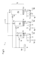
- Fig. 1 illustrates a schematic representation of a first embodiment of an inventive large diesel engine, which is generally designated by the reference numeral 1, and which may be designed as a two-stroke or four-stroke engine.
- Fig. 2 shows a schematic sectional view through one of the usually several cylinders 2 of the large diesel engine 1 from Fig. 1 , The cylinder 2 has a bore whose diameter is designated B, and a longitudinal axis A. The section in Fig. 2 is perpendicular to the longitudinal axis A of the cylinder. 2
- a piston 3 is arranged in a manner known per se to move back and forth, which moves in the operating state of the large diesel engine 1 along a running surface 21 on the inner wall of the cylinder 2.
- the tread 21 is formed by a cylinder insert or a liner.
- the piston 3 defines with its upper end according to the illustration a combustion chamber 4 in which the combustion process takes place, and usually has a plurality of piston rings, which are collectively referred to as the piston ring package 31.
- a lubricant for example a lubricating oil
- the running surface 21 which lubricates the piston 3, the piston ring pack 31 and the running surface in order to achieve good running properties of the piston 3 and the wear of the cylinder wall, to keep the piston 3 and the piston ring package 31 as low as possible.
- the lubricant is used to neutralize aggressive combustion products and to prevent corrosion, such as sulfur corrosion.
- a lubrication system 5 which comprises a plurality of lubrication points 6 via which the lubricant can be applied to the running surface 21.
- a total of eight lubrication points 6 are provided (see Fig. 2 ), which are arranged along the circumference of the cylinder 2.
- the lubrication points 6 each form the outlet opening of a nozzle 71, through which the lubricant is introduced into the cylinder 2.
- nozzle means all devices suitable for introducing the lubricant; these may be, for example, nozzles in the strict sense, through which the lubricant is injected or atomized as a concentrated jet, or channels or nozzles, for example, referred to as quills, through which the lubricant runs out or drips, or any other devices that are known for introducing the lubricant into the cylinder 2 of a large diesel engine 1.
- a lubricant supply 8 is provided to promote the lubricant from a lubricant reservoir 10 to the lubrication points 6.
- the lubricant reservoir 10 is a common rail memory or accumulator configured, which contains the lubricant under sufficient pressure, so that it can flow from the memory or accumulator to the lubrication points 6.
- the lubricant is provided by the common rail reservoir at a pressure of 1 to 20 bar.
- a pump not shown, promotes the lubricant from a reservoir, or that the lubricant is in a high tank as a lubricant reservoir from which the lubricant can flow out due to gravity.
- Fig. 2 shows - for each lubrication point 6 exactly one independently operable pump-nozzle unit 7 is provided and each pump-nozzle unit 7 supplies exactly one lubrication point 6, so that the number of pump-nozzle units 7 is the same size as the number of lubrication points ,
- the distance D ( Fig. 2 ) between the outlet of the pump 72 of the pump-nozzle unit 7 and the lubrication point 6 connected to this pump 72 is at most as large as the diameter B of the bore of the cylinder 2.
- the length of the nozzle 71 of the pump-nozzle Unit 7, which connects the output of the pump 72 with the lubrication point 6, preferably at most as large as the diameter of the bore of the cylinder. 2
- a check valve 73 is provided in each case (in Fig. 2 not shown) to prevent backflow of the lubricant from the lubrication point 6 to the pump 72.
- the pump 72 of the pump-nozzle unit 7 is designed as a piston pump, in which a working piston 74 is arranged in a pump chamber 75 movable back and forth. At each stroke of the working piston 74, a delivery of lubricant through the outlet of the pump 72 is fed into the nozzle 71.
- the control unit 12 has an automatic controller input 13 and a manual regulator input 14, which are each signal-connected to the control unit 12 (dashed arrows 201 and 202 in FIG Fig. 1 ).
- the automatic controller input 13 receives, preferably in real time, automatically input signals which contain information about the current operating state, such as speed or load of the engine, or other system parameters, such as position or position of the crankshaft. On the basis of these input signals, the times and, if appropriate, the quantities and the lubrication points 6 to be activated for the lubricant entry onto the running surface 21 are determined.
- parameters or specifications can be transmitted to the control unit 12 by hand.
- the control unit 12 via the signal line 200 is a control pulse, so that the solenoid brings the switching element in the other switching position.
- the back of the working piston 74 is connected to the pressure accumulator for the activation medium.
- the activation medium flows from the pressure accumulator 11 via connecting lines 102 and 101 against the back of the working piston 74 and moves it to the right until it reaches its right reversal point or stop according to the illustration.
- the lubricant in the pump chamber 75 is pushed out through the nozzle 71 and reaches the running surface 21 in the cylinder 2 via the lubricating point 6.
- control unit 12 is activated by the spring 92, the switching element 9 back into the in Fig. 1 shown switching position, whereby the activation medium flows from the back of the Arbeistkolbens 74 in the outlet line 103, whereby the working piston 74 moves again in its representation according to the left reversal point and the pump chamber 75 is filled via the line 100 again with lubricant.
- the activation medium is compressed air, it can simply be blown off through the outlet line 103. If the activation medium is on Pressure oil or hydraulic fluid, it can be discharged via the outlet line 103 as return and then the pressure accumulator 11, which is configured for example as a common rail memory, are supplied.
- a direct electrical actuation of the pump 72 is possible, in which the working piston 74 directly by means of electromagnetic forces by coils and / or by otherwise electrically activated signal or pulse generator, for. B. piezocrystal activated, is moved back and forth.
- switching member 9 actuates a plurality of pumps 72 different pump-nozzle units 7.
- the switching member 9 actuates a plurality of pumps 72 different pump-nozzle units 7.
- Fig. 3 shows the pump-nozzle unit 7 of a second embodiment of a large diesel engine according to the invention 1. From the function of equal or equivalent parts are provided with the same reference numerals as in Fig. 1 respectively.
- Fig. 2 shows the pump-nozzle unit 7 of a second embodiment of a large diesel engine according to the invention 1. From the function of equal or equivalent parts are provided with the same reference numerals as in Fig. 1 respectively.
- Fig. 2 shows the pump-nozzle unit 7 of a second embodiment of a large diesel engine according to the invention 1. From the function of equal or equivalent parts are provided with the same reference numerals as in Fig. 1 respectively.
- Fig. 2 shows the pump-nozzle unit 7 of a second embodiment of a large diesel engine according to the invention 1. From the function of equal or equivalent parts. Fig. 2 ,
- the pump-nozzle unit 7 is connected to two lubrication points 6.
- the pump-nozzle unit 7 is arranged so that the distance from the output of the pump 72 to the lubrication point 6 for both lubrication points 6 is equal.
- the nozzle 71 is here designed as a forked nozzle 71, which splits into the two arms 71 a and 71 b, each of which leads to a lubrication point 6.
- the symmetrical design of the nozzle 71 ensures that the supply of both lubrication points takes place completely simultaneously.
- the length of the nozzle 71 measured either over the arm 71 a or over the arm 71 b at most as large as the diameter B of the bore of the cylinder. 2
- Fig. 4 shows a variant of the arrangement of the lubrication points 6, which is possible for both the first and the second embodiment.
- the lubrication point 6' is arranged further down as shown, while the lubrication point 6" according to the illustration above, ie closer to Combustion chamber 4 is arranged.
- a lubricant can be used in the vicinity of the combustion chamber 4 through the lubrication point 6", which is particularly favorable in terms of the neutralization of aggressive combustion products, while further away from the combustion chamber 4 through the lubrication point 6 ', a lubricant is used, that in terms of sliding properties is particularly favorable. It is also possible, depending on the operating condition of the engine, e.g. Part load or full load to use different lubricants for cylinder lubrication.
- Fig. 5 shows a schematic representation of a variant for the pump-nozzle unit 7, which is possible for both the first and the second embodiment.
- the pump-nozzle unit 7 comprises a plurality, here namely three working pistons 741, 742 and 743, each of which is arranged in a separate pumping space 751, 752 and 753, respectively.
- a Switching member 9 ', 9 ", or 9"' provided to actuate the respective working piston 741, 742, and 743 in a manner analogous to the way already described above.
- This variant in addition to the already mentioned stroke-controlled promotion is a means to adjust the amount of lubricant delivered by the pump-nozzle unit 7 to a predefinable value, namely by only one or two or all three of the working piston 741, 742, per lubrication 743 is actuated.
- the pumping spaces 751, 752, 753 may have the same or different volume.
- the pumping space 751 has the smallest volume
- the pumping space 752 has the second largest volume
- the pumping space 753 has the largest volume. Accordingly, at a constant delivery at which the pumping space 751, 752, 753 is completely emptied completely by the working piston 741, 742, 743, the delivery rate per working cycle will be smallest, if only the working piston 741 is actuated. If only one working piston 741, 742, 743 is actuated in each case, the delivery rate is greatest when the working piston 743 is actuated.
Landscapes
- Engineering & Computer Science (AREA)
- Mechanical Engineering (AREA)
- General Engineering & Computer Science (AREA)
- Lubrication Of Internal Combustion Engines (AREA)
- Fuel-Injection Apparatus (AREA)
Priority Applications (1)
| Application Number | Priority Date | Filing Date | Title |
|---|---|---|---|
| EP09169466.1A EP2177720B1 (fr) | 2008-10-16 | 2009-09-04 | Grand moteur diesel |
Applications Claiming Priority (2)
| Application Number | Priority Date | Filing Date | Title |
|---|---|---|---|
| EP08166804 | 2008-10-16 | ||
| EP09169466.1A EP2177720B1 (fr) | 2008-10-16 | 2009-09-04 | Grand moteur diesel |
Publications (2)
| Publication Number | Publication Date |
|---|---|
| EP2177720A1 true EP2177720A1 (fr) | 2010-04-21 |
| EP2177720B1 EP2177720B1 (fr) | 2014-04-09 |
Family
ID=40210540
Family Applications (1)
| Application Number | Title | Priority Date | Filing Date |
|---|---|---|---|
| EP09169466.1A Not-in-force EP2177720B1 (fr) | 2008-10-16 | 2009-09-04 | Grand moteur diesel |
Country Status (6)
| Country | Link |
|---|---|
| EP (1) | EP2177720B1 (fr) |
| JP (2) | JP5676869B2 (fr) |
| KR (1) | KR101602303B1 (fr) |
| CN (2) | CN101725385A (fr) |
| DK (1) | DK2177720T3 (fr) |
| RU (1) | RU2505685C2 (fr) |
Cited By (6)
| Publication number | Priority date | Publication date | Assignee | Title |
|---|---|---|---|---|
| EP2395208A1 (fr) | 2010-06-11 | 2011-12-14 | Wärtsilä Schweiz AG | Grand moteur doté d'un dispositif de lubrification de cylindre et procédé de lubrification d'un cylindre d'un grand moteur |
| DE102013002744A1 (de) | 2013-02-19 | 2014-08-21 | Man Diesel & Turbo, Filial Af Man Diesel & Turbo Se, Tyskland | System zur Beeinflussung der Gleiteigenschaften einer Gleitpaarung |
| EP3212985A4 (fr) * | 2014-10-30 | 2018-06-13 | Jukka Moksi | Système de lubrification automatique et procédé de lubrification de pièces |
| WO2019114904A1 (fr) | 2017-12-13 | 2019-06-20 | Hans Jensen Lubricators A/S | Gros moteur lent à deux temps et procédé de lubrification d'un tel moteur, et injecteur doté de système de pompage électrique pour un tel moteur et procédé associé |
| DE102013002743B4 (de) * | 2013-02-19 | 2020-09-03 | Man Diesel & Turbo, Filial Af Man Diesel & Turbo Se, Tyskland | Vorrichtung zur Zylinderschmierung |
| EP3724464A4 (fr) * | 2017-12-13 | 2021-08-18 | Hans Jensen Lubricators A/S | Gros moteur à deux temps lent, procédé de lubrification de celui-ci, et injecteur doté d'un système de pompage hydraulique pas à pas pour un tel moteur et procédé |
Families Citing this family (8)
| Publication number | Priority date | Publication date | Assignee | Title |
|---|---|---|---|---|
| EP2620607B1 (fr) * | 2012-01-30 | 2015-08-12 | Wärtsilä Schweiz AG | Ensemble piston-cylindre et procédé d'alimentation en lubrifiant de l'ensemble piston-cylindre pour un moteur à combustion interne |
| CN102588034B (zh) * | 2012-03-19 | 2013-12-18 | 上海三一重机有限公司 | 一种发动机智能实时保护装置 |
| CN103527282B (zh) * | 2012-07-04 | 2017-06-30 | 瓦锡兰瑞士公司 | 润滑系统、润滑剂注入元件、内燃发动机以及润滑方法 |
| JP6685864B2 (ja) * | 2016-08-29 | 2020-04-22 | 三菱重工業株式会社 | シリンダ注油装置及びクロスヘッド式内燃機関 |
| EP3404224A1 (fr) * | 2017-05-19 | 2018-11-21 | Winterthur Gas & Diesel AG | Dispositif de lubrification pour un gros moteur diesel, procédé de lubrification de cylindre d'un gros moteur diesel et gros moteur diesel |
| EP3483403B1 (fr) * | 2017-11-09 | 2022-11-30 | Winterthur Gas & Diesel AG | Dispositif de lubrification pour un moteur diesel de grande dimension |
| DK179482B1 (en) * | 2017-12-13 | 2018-12-14 | Hans Jensen Lubricators A/S | A large slow-running two-stroke engine, a method of lubricating it, and an injector with a hydraulic-driven pumping system for such engine and method |
| DK179952B1 (en) * | 2018-07-06 | 2019-10-25 | Hans Jensen Lubricators A/S | A METHOD FOR UPGRADING A LUBRICATION SYSTEM IN A LARGE SLOW-RUNNING TWO-STROKE ENGINE |
Citations (6)
| Publication number | Priority date | Publication date | Assignee | Title |
|---|---|---|---|---|
| JPH0267410A (ja) * | 1988-09-02 | 1990-03-07 | Ishikawajima Harima Heavy Ind Co Ltd | シリンダ注油配管方法 |
| CH673506A5 (en) * | 1987-11-05 | 1990-03-15 | Sulzer Ag | Cylinder lubrication device for IC engine - has common hydraulic drive coupled to piston-cylinder system for each lubrication stroke around wall of each engine cylinder |
| JPH03249318A (ja) * | 1990-02-28 | 1991-11-07 | Kubota Corp | 多気筒部分油冷エンジンの潤滑装置 |
| WO2000028194A1 (fr) * | 1998-11-05 | 2000-05-18 | Hans Jensen Lubricators A/S | Systeme de lubrification pour moteurs diesel de grande taille |
| DE10220015A1 (de) * | 2001-05-07 | 2002-11-21 | Man B & W Diesel As Kopenhagen | Verfahren zum Einspritzen von Schmieröl in einen Zylinder eines Verbrennungsmotors |
| EP1582706A2 (fr) * | 2004-03-31 | 2005-10-05 | Mitsubishi Heavy Industries, Ltd. | Moteur à combustion interne ayant un dispositif de lubrification du cylindre |
Family Cites Families (15)
| Publication number | Priority date | Publication date | Assignee | Title |
|---|---|---|---|---|
| DE2830506C2 (de) * | 1978-07-12 | 1983-11-17 | M.A.N. Maschinenfabrik Augsburg-Nürnberg AG, 8900 Augsburg | Einrichtung zur Zufuhr von Schmieröl in die Zylinderbuchse einer Brennkraftmaschine |
| DE3044255A1 (de) * | 1980-11-25 | 1982-06-24 | M.A.N. Maschinenfabrik Augsburg-Nürnberg AG, 8900 Augsburg | Zylinder- und kolben-schmiervorrichtung an einer brennkraftmaschine |
| JPS58165515A (ja) * | 1982-03-26 | 1983-09-30 | Mitsui Eng & Shipbuild Co Ltd | デイ−ゼル機関のシリンダ注油方法および装置 |
| SU1562482A1 (ru) * | 1987-09-21 | 1990-05-07 | А.С,Пилюгин, Ю.Н.Довиденко, В.М.Богач, В.А.Вузовский, Л.К.Крыштын, Н.И.Муха и О.Н.Занько | Система смазки цилиндра двигател |
| JPH0228508U (fr) * | 1988-08-16 | 1990-02-23 | ||
| DK171974B1 (da) * | 1988-11-01 | 1997-09-01 | Mitsubishi Heavy Ind Ltd | Smøreaggregat til en cylinder i en forbrændingsmotor |
| DK98391D0 (da) * | 1991-05-24 | 1991-05-24 | Jensens Hans Maskinfabrik | Smoeresystem til successive doseringer af olie til smoeresteder i store stempelmaskinecylindre |
| CN1068406C (zh) * | 1992-11-24 | 2001-07-11 | 汉斯·詹森斯·玛斯金菲布里克有限公司 | 舰用柴油机上大活塞机内用于活塞点润滑的润滑系统 |
| US5533875A (en) * | 1995-04-07 | 1996-07-09 | American Standard Inc. | Scroll compressor having a frame and open sleeve for controlling gas and lubricant flow |
| DE19959300A1 (de) * | 1999-12-09 | 2001-06-21 | Man B & W Diesel As Kopenhagen | Motor |
| US6928975B2 (en) * | 2000-10-24 | 2005-08-16 | Hans Jensen Lubricators A/S | Dosing system |
| DK200400958A (da) * | 2004-06-18 | 2005-12-19 | Hans Jensen Lubricators As | Doseringssystem |
| DK176742B1 (da) * | 2004-06-30 | 2009-06-02 | Hans Jensen Lubricators As | Fremgangsmåde og apparat til smöring af cylinderfladerne i store dieselmotorer |
| CN101054930B (zh) * | 2006-04-11 | 2010-09-08 | 浙江飞亚电子有限公司 | 一种电磁燃油泵喷嘴的驱动控制方法及其装置 |
| DK200601005A (da) * | 2006-07-21 | 2008-01-22 | Hans Jensen Lubricators As | Smöreapparat til et doseringssystem for cylindersmöreolie samt fremgangsmåde til dosering af cylindersmöreolie |
-
2009
- 2009-09-04 DK DK09169466T patent/DK2177720T3/da active
- 2009-09-04 EP EP09169466.1A patent/EP2177720B1/fr not_active Not-in-force
- 2009-10-15 KR KR1020090098227A patent/KR101602303B1/ko active IP Right Grant
- 2009-10-15 CN CN200910208245A patent/CN101725385A/zh active Pending
- 2009-10-15 CN CN201610238385.4A patent/CN105888766A/zh active Pending
- 2009-10-15 JP JP2009238348A patent/JP5676869B2/ja not_active Expired - Fee Related
- 2009-10-15 RU RU2009138193/06A patent/RU2505685C2/ru not_active IP Right Cessation
-
2014
- 2014-10-24 JP JP2014217713A patent/JP2015025457A/ja active Pending
Patent Citations (6)
| Publication number | Priority date | Publication date | Assignee | Title |
|---|---|---|---|---|
| CH673506A5 (en) * | 1987-11-05 | 1990-03-15 | Sulzer Ag | Cylinder lubrication device for IC engine - has common hydraulic drive coupled to piston-cylinder system for each lubrication stroke around wall of each engine cylinder |
| JPH0267410A (ja) * | 1988-09-02 | 1990-03-07 | Ishikawajima Harima Heavy Ind Co Ltd | シリンダ注油配管方法 |
| JPH03249318A (ja) * | 1990-02-28 | 1991-11-07 | Kubota Corp | 多気筒部分油冷エンジンの潤滑装置 |
| WO2000028194A1 (fr) * | 1998-11-05 | 2000-05-18 | Hans Jensen Lubricators A/S | Systeme de lubrification pour moteurs diesel de grande taille |
| DE10220015A1 (de) * | 2001-05-07 | 2002-11-21 | Man B & W Diesel As Kopenhagen | Verfahren zum Einspritzen von Schmieröl in einen Zylinder eines Verbrennungsmotors |
| EP1582706A2 (fr) * | 2004-03-31 | 2005-10-05 | Mitsubishi Heavy Industries, Ltd. | Moteur à combustion interne ayant un dispositif de lubrification du cylindre |
Cited By (8)
| Publication number | Priority date | Publication date | Assignee | Title |
|---|---|---|---|---|
| EP2395208A1 (fr) | 2010-06-11 | 2011-12-14 | Wärtsilä Schweiz AG | Grand moteur doté d'un dispositif de lubrification de cylindre et procédé de lubrification d'un cylindre d'un grand moteur |
| DE102013002744A1 (de) | 2013-02-19 | 2014-08-21 | Man Diesel & Turbo, Filial Af Man Diesel & Turbo Se, Tyskland | System zur Beeinflussung der Gleiteigenschaften einer Gleitpaarung |
| DE102013002743B4 (de) * | 2013-02-19 | 2020-09-03 | Man Diesel & Turbo, Filial Af Man Diesel & Turbo Se, Tyskland | Vorrichtung zur Zylinderschmierung |
| DE102013002744B4 (de) | 2013-02-19 | 2022-12-29 | MAN Energy Solutions, filial af MAN Energy Solutions SE, Germany | System zur Beeinflussung der Gleiteigenschaften einer Gleitpaarung |
| EP3212985A4 (fr) * | 2014-10-30 | 2018-06-13 | Jukka Moksi | Système de lubrification automatique et procédé de lubrification de pièces |
| WO2019114904A1 (fr) | 2017-12-13 | 2019-06-20 | Hans Jensen Lubricators A/S | Gros moteur lent à deux temps et procédé de lubrification d'un tel moteur, et injecteur doté de système de pompage électrique pour un tel moteur et procédé associé |
| EP3724464A4 (fr) * | 2017-12-13 | 2021-08-18 | Hans Jensen Lubricators A/S | Gros moteur à deux temps lent, procédé de lubrification de celui-ci, et injecteur doté d'un système de pompage hydraulique pas à pas pour un tel moteur et procédé |
| EP3724466A4 (fr) * | 2017-12-13 | 2021-08-25 | Hans Jensen Lubricators A/S | Gros moteur lent à deux temps et procédé de lubrification d'un tel moteur, et injecteur doté de système de pompage électrique pour un tel moteur et procédé associé |
Also Published As
| Publication number | Publication date |
|---|---|
| RU2505685C2 (ru) | 2014-01-27 |
| EP2177720B1 (fr) | 2014-04-09 |
| JP2015025457A (ja) | 2015-02-05 |
| CN101725385A (zh) | 2010-06-09 |
| JP2010096181A (ja) | 2010-04-30 |
| JP5676869B2 (ja) | 2015-02-25 |
| CN105888766A (zh) | 2016-08-24 |
| RU2009138193A (ru) | 2011-04-20 |
| KR101602303B1 (ko) | 2016-03-10 |
| KR20100042605A (ko) | 2010-04-26 |
| DK2177720T3 (da) | 2014-06-30 |
Similar Documents
| Publication | Publication Date | Title |
|---|---|---|
| EP2177720B1 (fr) | Grand moteur diesel | |
| DE102013104822B4 (de) | Zylinder-schmiervorrichtung für einen grossen; langsam laufenden zweitakt-dieselmotor und verfahren zum betreiben des zylinder-schmiersystems | |
| DE60215036T2 (de) | Schmiermitteleinspritzung | |
| DE867558C (de) | Von einem Schienenfahrzeug getragener Schienenschmierer | |
| EP2395208A1 (fr) | Grand moteur doté d'un dispositif de lubrification de cylindre et procédé de lubrification d'un cylindre d'un grand moteur | |
| DE10220015A1 (de) | Verfahren zum Einspritzen von Schmieröl in einen Zylinder eines Verbrennungsmotors | |
| DE19625698B4 (de) | Einspritzeinrichtung zum kombinierten Einspritzen von Kraftstoff und Zusatzflüssigkeit | |
| DE19959300A1 (de) | Motor | |
| DE19531870C2 (de) | Kraftstoffeinspritzsystem | |
| DE102013002743B4 (de) | Vorrichtung zur Zylinderschmierung | |
| DE1947529A1 (de) | Kraftstoffeinspritzpumpe fuer Brennkraftmaschinen | |
| EP1350929A1 (fr) | Dispositif de graissage pour un cilndre d'un moteur et procédure pour le graisser | |
| EP3483420B1 (fr) | Buse d'injection de carburant et procédé d'injection de carburant pour un gros moteur diesel ainsi que gros moteur diesel | |
| DE102013104821B4 (de) | Zylinder-Schmiervorrichtung | |
| DD243067A5 (de) | Einspritzsystem fuer einen dieselmotor mit einer hochdruck-einspritzpumpe fuer jeden zylinder | |
| EP2093394A1 (fr) | Dispositif destiné au graissage de cylindres | |
| EP0903473A1 (fr) | Moteur diesel et méthode de fonctionnement | |
| WO2016055293A1 (fr) | Système d'injection d'accumulateur pour moteurs a combustion interne | |
| DE102011083005B4 (de) | Verfahren zur Spülung eines Ankerraums eines zur Steuerung eines Fluidmassenstroms vorgesehenen Magnetventils und Magnetventil | |
| EP2682572B1 (fr) | Système de lubrification | |
| DE19959309A1 (de) | Motor | |
| AT521887A1 (de) | System und Verfahren zum Einstellen einer wirksamen Länge einer Pleuelstange mittels Schmiermittelversorgung | |
| DE2716854A1 (de) | Kraftstoff-foerderanlage | |
| DE3130442C2 (fr) | ||
| DE10149125B4 (de) | Zylinderschmiervorrichtung |
Legal Events
| Date | Code | Title | Description |
|---|---|---|---|
| PUAI | Public reference made under article 153(3) epc to a published international application that has entered the european phase |
Free format text: ORIGINAL CODE: 0009012 |
|
| AK | Designated contracting states |
Kind code of ref document: A1 Designated state(s): AT BE BG CH CY CZ DE DK EE ES FI FR GB GR HR HU IE IS IT LI LT LU LV MC MK MT NL NO PL PT RO SE SI SK SM TR |
|
| 17P | Request for examination filed |
Effective date: 20101021 |
|
| 17Q | First examination report despatched |
Effective date: 20101123 |
|
| GRAP | Despatch of communication of intention to grant a patent |
Free format text: ORIGINAL CODE: EPIDOSNIGR1 |
|
| INTG | Intention to grant announced |
Effective date: 20131118 |
|
| GRAS | Grant fee paid |
Free format text: ORIGINAL CODE: EPIDOSNIGR3 |
|
| GRAA | (expected) grant |
Free format text: ORIGINAL CODE: 0009210 |
|
| AK | Designated contracting states |
Kind code of ref document: B1 Designated state(s): AT BE BG CH CY CZ DE DK EE ES FI FR GB GR HR HU IE IS IT LI LT LU LV MC MK MT NL NO PL PT RO SE SI SK SM TR |
|
| REG | Reference to a national code |
Ref country code: GB Ref legal event code: FG4D Free format text: NOT ENGLISH |
|
| REG | Reference to a national code |
Ref country code: CH Ref legal event code: EP Ref country code: AT Ref legal event code: REF Ref document number: 661475 Country of ref document: AT Kind code of ref document: T Effective date: 20140415 |
|
| REG | Reference to a national code |
Ref country code: IE Ref legal event code: FG4D Free format text: LANGUAGE OF EP DOCUMENT: GERMAN |
|
| REG | Reference to a national code |
Ref country code: DE Ref legal event code: R096 Ref document number: 502009009136 Country of ref document: DE Effective date: 20140522 |
|
| REG | Reference to a national code |
Ref country code: DK Ref legal event code: T3 Effective date: 20140627 |
|
| REG | Reference to a national code |
Ref country code: NL Ref legal event code: VDEP Effective date: 20140409 |
|
| REG | Reference to a national code |
Ref country code: LT Ref legal event code: MG4D |
|
| PG25 | Lapsed in a contracting state [announced via postgrant information from national office to epo] |
Ref country code: NL Free format text: LAPSE BECAUSE OF FAILURE TO SUBMIT A TRANSLATION OF THE DESCRIPTION OR TO PAY THE FEE WITHIN THE PRESCRIBED TIME-LIMIT Effective date: 20140409 Ref country code: FI Free format text: LAPSE BECAUSE OF FAILURE TO SUBMIT A TRANSLATION OF THE DESCRIPTION OR TO PAY THE FEE WITHIN THE PRESCRIBED TIME-LIMIT Effective date: 20140409 Ref country code: LT Free format text: LAPSE BECAUSE OF FAILURE TO SUBMIT A TRANSLATION OF THE DESCRIPTION OR TO PAY THE FEE WITHIN THE PRESCRIBED TIME-LIMIT Effective date: 20140409 Ref country code: GR Free format text: LAPSE BECAUSE OF FAILURE TO SUBMIT A TRANSLATION OF THE DESCRIPTION OR TO PAY THE FEE WITHIN THE PRESCRIBED TIME-LIMIT Effective date: 20140710 Ref country code: BG Free format text: LAPSE BECAUSE OF FAILURE TO SUBMIT A TRANSLATION OF THE DESCRIPTION OR TO PAY THE FEE WITHIN THE PRESCRIBED TIME-LIMIT Effective date: 20140709 Ref country code: IS Free format text: LAPSE BECAUSE OF FAILURE TO SUBMIT A TRANSLATION OF THE DESCRIPTION OR TO PAY THE FEE WITHIN THE PRESCRIBED TIME-LIMIT Effective date: 20140809 Ref country code: NO Free format text: LAPSE BECAUSE OF FAILURE TO SUBMIT A TRANSLATION OF THE DESCRIPTION OR TO PAY THE FEE WITHIN THE PRESCRIBED TIME-LIMIT Effective date: 20140709 |
|
| PG25 | Lapsed in a contracting state [announced via postgrant information from national office to epo] |
Ref country code: SE Free format text: LAPSE BECAUSE OF FAILURE TO SUBMIT A TRANSLATION OF THE DESCRIPTION OR TO PAY THE FEE WITHIN THE PRESCRIBED TIME-LIMIT Effective date: 20140409 Ref country code: LV Free format text: LAPSE BECAUSE OF FAILURE TO SUBMIT A TRANSLATION OF THE DESCRIPTION OR TO PAY THE FEE WITHIN THE PRESCRIBED TIME-LIMIT Effective date: 20140409 Ref country code: ES Free format text: LAPSE BECAUSE OF FAILURE TO SUBMIT A TRANSLATION OF THE DESCRIPTION OR TO PAY THE FEE WITHIN THE PRESCRIBED TIME-LIMIT Effective date: 20140409 Ref country code: HR Free format text: LAPSE BECAUSE OF FAILURE TO SUBMIT A TRANSLATION OF THE DESCRIPTION OR TO PAY THE FEE WITHIN THE PRESCRIBED TIME-LIMIT Effective date: 20140409 Ref country code: PL Free format text: LAPSE BECAUSE OF FAILURE TO SUBMIT A TRANSLATION OF THE DESCRIPTION OR TO PAY THE FEE WITHIN THE PRESCRIBED TIME-LIMIT Effective date: 20140409 |
|
| PG25 | Lapsed in a contracting state [announced via postgrant information from national office to epo] |
Ref country code: PT Free format text: LAPSE BECAUSE OF FAILURE TO SUBMIT A TRANSLATION OF THE DESCRIPTION OR TO PAY THE FEE WITHIN THE PRESCRIBED TIME-LIMIT Effective date: 20140811 |
|
| REG | Reference to a national code |
Ref country code: DE Ref legal event code: R097 Ref document number: 502009009136 Country of ref document: DE |
|
| PG25 | Lapsed in a contracting state [announced via postgrant information from national office to epo] |
Ref country code: CZ Free format text: LAPSE BECAUSE OF FAILURE TO SUBMIT A TRANSLATION OF THE DESCRIPTION OR TO PAY THE FEE WITHIN THE PRESCRIBED TIME-LIMIT Effective date: 20140409 Ref country code: SK Free format text: LAPSE BECAUSE OF FAILURE TO SUBMIT A TRANSLATION OF THE DESCRIPTION OR TO PAY THE FEE WITHIN THE PRESCRIBED TIME-LIMIT Effective date: 20140409 Ref country code: EE Free format text: LAPSE BECAUSE OF FAILURE TO SUBMIT A TRANSLATION OF THE DESCRIPTION OR TO PAY THE FEE WITHIN THE PRESCRIBED TIME-LIMIT Effective date: 20140409 Ref country code: RO Free format text: LAPSE BECAUSE OF FAILURE TO SUBMIT A TRANSLATION OF THE DESCRIPTION OR TO PAY THE FEE WITHIN THE PRESCRIBED TIME-LIMIT Effective date: 20140409 |
|
| PLBE | No opposition filed within time limit |
Free format text: ORIGINAL CODE: 0009261 |
|
| STAA | Information on the status of an ep patent application or granted ep patent |
Free format text: STATUS: NO OPPOSITION FILED WITHIN TIME LIMIT |
|
| 26N | No opposition filed |
Effective date: 20150112 |
|
| PG25 | Lapsed in a contracting state [announced via postgrant information from national office to epo] |
Ref country code: IT Free format text: LAPSE BECAUSE OF FAILURE TO SUBMIT A TRANSLATION OF THE DESCRIPTION OR TO PAY THE FEE WITHIN THE PRESCRIBED TIME-LIMIT Effective date: 20140409 |
|
| REG | Reference to a national code |
Ref country code: DE Ref legal event code: R097 Ref document number: 502009009136 Country of ref document: DE Effective date: 20150112 |
|
| PG25 | Lapsed in a contracting state [announced via postgrant information from national office to epo] |
Ref country code: MC Free format text: LAPSE BECAUSE OF FAILURE TO SUBMIT A TRANSLATION OF THE DESCRIPTION OR TO PAY THE FEE WITHIN THE PRESCRIBED TIME-LIMIT Effective date: 20140409 Ref country code: LU Free format text: LAPSE BECAUSE OF FAILURE TO SUBMIT A TRANSLATION OF THE DESCRIPTION OR TO PAY THE FEE WITHIN THE PRESCRIBED TIME-LIMIT Effective date: 20140904 |
|
| REG | Reference to a national code |
Ref country code: CH Ref legal event code: PL |
|
| GBPC | Gb: european patent ceased through non-payment of renewal fee |
Effective date: 20140904 |
|
| REG | Reference to a national code |
Ref country code: IE Ref legal event code: MM4A |
|
| REG | Reference to a national code |
Ref country code: FR Ref legal event code: ST Effective date: 20150529 |
|
| PG25 | Lapsed in a contracting state [announced via postgrant information from national office to epo] |
Ref country code: BE Free format text: LAPSE BECAUSE OF NON-PAYMENT OF DUE FEES Effective date: 20140930 |
|
| PG25 | Lapsed in a contracting state [announced via postgrant information from national office to epo] |
Ref country code: GB Free format text: LAPSE BECAUSE OF NON-PAYMENT OF DUE FEES Effective date: 20140904 Ref country code: CH Free format text: LAPSE BECAUSE OF NON-PAYMENT OF DUE FEES Effective date: 20140930 Ref country code: SI Free format text: LAPSE BECAUSE OF FAILURE TO SUBMIT A TRANSLATION OF THE DESCRIPTION OR TO PAY THE FEE WITHIN THE PRESCRIBED TIME-LIMIT Effective date: 20140409 Ref country code: LI Free format text: LAPSE BECAUSE OF NON-PAYMENT OF DUE FEES Effective date: 20140930 |
|
| PG25 | Lapsed in a contracting state [announced via postgrant information from national office to epo] |
Ref country code: IE Free format text: LAPSE BECAUSE OF NON-PAYMENT OF DUE FEES Effective date: 20140904 Ref country code: FR Free format text: LAPSE BECAUSE OF NON-PAYMENT OF DUE FEES Effective date: 20140930 |
|
| REG | Reference to a national code |
Ref country code: AT Ref legal event code: MM01 Ref document number: 661475 Country of ref document: AT Kind code of ref document: T Effective date: 20140904 |
|
| PG25 | Lapsed in a contracting state [announced via postgrant information from national office to epo] |
Ref country code: AT Free format text: LAPSE BECAUSE OF NON-PAYMENT OF DUE FEES Effective date: 20140904 |
|
| PG25 | Lapsed in a contracting state [announced via postgrant information from national office to epo] |
Ref country code: SM Free format text: LAPSE BECAUSE OF FAILURE TO SUBMIT A TRANSLATION OF THE DESCRIPTION OR TO PAY THE FEE WITHIN THE PRESCRIBED TIME-LIMIT Effective date: 20140409 |
|
| PG25 | Lapsed in a contracting state [announced via postgrant information from national office to epo] |
Ref country code: CY Free format text: LAPSE BECAUSE OF FAILURE TO SUBMIT A TRANSLATION OF THE DESCRIPTION OR TO PAY THE FEE WITHIN THE PRESCRIBED TIME-LIMIT Effective date: 20140409 Ref country code: MT Free format text: LAPSE BECAUSE OF FAILURE TO SUBMIT A TRANSLATION OF THE DESCRIPTION OR TO PAY THE FEE WITHIN THE PRESCRIBED TIME-LIMIT Effective date: 20140409 |
|
| PG25 | Lapsed in a contracting state [announced via postgrant information from national office to epo] |
Ref country code: TR Free format text: LAPSE BECAUSE OF FAILURE TO SUBMIT A TRANSLATION OF THE DESCRIPTION OR TO PAY THE FEE WITHIN THE PRESCRIBED TIME-LIMIT Effective date: 20140409 Ref country code: HU Free format text: LAPSE BECAUSE OF FAILURE TO SUBMIT A TRANSLATION OF THE DESCRIPTION OR TO PAY THE FEE WITHIN THE PRESCRIBED TIME-LIMIT; INVALID AB INITIO Effective date: 20090904 |
|
| PG25 | Lapsed in a contracting state [announced via postgrant information from national office to epo] |
Ref country code: MK Free format text: LAPSE BECAUSE OF FAILURE TO SUBMIT A TRANSLATION OF THE DESCRIPTION OR TO PAY THE FEE WITHIN THE PRESCRIBED TIME-LIMIT Effective date: 20140409 |
|
| PGFP | Annual fee paid to national office [announced via postgrant information from national office to epo] |
Ref country code: DE Payment date: 20200925 Year of fee payment: 12 Ref country code: DK Payment date: 20200922 Year of fee payment: 12 |
|
| REG | Reference to a national code |
Ref country code: DE Ref legal event code: R119 Ref document number: 502009009136 Country of ref document: DE |
|
| REG | Reference to a national code |
Ref country code: DK Ref legal event code: EBP Effective date: 20210930 |
|
| PG25 | Lapsed in a contracting state [announced via postgrant information from national office to epo] |
Ref country code: DE Free format text: LAPSE BECAUSE OF NON-PAYMENT OF DUE FEES Effective date: 20220401 |
|
| PG25 | Lapsed in a contracting state [announced via postgrant information from national office to epo] |
Ref country code: DK Free format text: LAPSE BECAUSE OF NON-PAYMENT OF DUE FEES Effective date: 20210930 |