EP2177464A2 - Dokumentzuführer und Dokumentabtastvorrichtung damit - Google Patents
Dokumentzuführer und Dokumentabtastvorrichtung damit Download PDFInfo
- Publication number
- EP2177464A2 EP2177464A2 EP09170934A EP09170934A EP2177464A2 EP 2177464 A2 EP2177464 A2 EP 2177464A2 EP 09170934 A EP09170934 A EP 09170934A EP 09170934 A EP09170934 A EP 09170934A EP 2177464 A2 EP2177464 A2 EP 2177464A2
- Authority
- EP
- European Patent Office
- Prior art keywords
- document
- path
- flap
- mode
- reversal path
- Prior art date
- Legal status (The legal status is an assumption and is not a legal conclusion. Google has not performed a legal analysis and makes no representation as to the accuracy of the status listed.)
- Granted
Links
- 238000011144 upstream manufacturing Methods 0.000 claims abstract description 21
- 238000000034 method Methods 0.000 description 7
- 238000000926 separation method Methods 0.000 description 7
- 239000013256 coordination polymer Substances 0.000 description 5
- 238000005452 bending Methods 0.000 description 4
- 239000011521 glass Substances 0.000 description 4
- 238000007599 discharging Methods 0.000 description 3
- 230000000694 effects Effects 0.000 description 3
- 239000000463 material Substances 0.000 description 3
- 238000012986 modification Methods 0.000 description 2
- 230000004048 modification Effects 0.000 description 2
- 238000005516 engineering process Methods 0.000 description 1
- -1 structures Substances 0.000 description 1
- 239000000126 substance Substances 0.000 description 1
Images


Classifications
-
- B—PERFORMING OPERATIONS; TRANSPORTING
- B65—CONVEYING; PACKING; STORING; HANDLING THIN OR FILAMENTARY MATERIAL
- B65H—HANDLING THIN OR FILAMENTARY MATERIAL, e.g. SHEETS, WEBS, CABLES
- B65H31/00—Pile receivers
- B65H31/02—Pile receivers with stationary end support against which pile accumulates
-
- B—PERFORMING OPERATIONS; TRANSPORTING
- B65—CONVEYING; PACKING; STORING; HANDLING THIN OR FILAMENTARY MATERIAL
- B65H—HANDLING THIN OR FILAMENTARY MATERIAL, e.g. SHEETS, WEBS, CABLES
- B65H29/00—Delivering or advancing articles from machines; Advancing articles to or into piles
- B65H29/58—Article switches or diverters
- B65H29/60—Article switches or diverters diverting the stream into alternative paths
-
- G—PHYSICS
- G03—PHOTOGRAPHY; CINEMATOGRAPHY; ANALOGOUS TECHNIQUES USING WAVES OTHER THAN OPTICAL WAVES; ELECTROGRAPHY; HOLOGRAPHY
- G03G—ELECTROGRAPHY; ELECTROPHOTOGRAPHY; MAGNETOGRAPHY
- G03G15/00—Apparatus for electrographic processes using a charge pattern
- G03G15/60—Apparatus which relate to the handling of originals
- G03G15/602—Apparatus which relate to the handling of originals for transporting
-
- H—ELECTRICITY
- H04—ELECTRIC COMMUNICATION TECHNIQUE
- H04N—PICTORIAL COMMUNICATION, e.g. TELEVISION
- H04N1/00—Scanning, transmission or reproduction of documents or the like, e.g. facsimile transmission; Details thereof
- H04N1/00567—Handling of original or reproduction media, e.g. cutting, separating, stacking
-
- H—ELECTRICITY
- H04—ELECTRIC COMMUNICATION TECHNIQUE
- H04N—PICTORIAL COMMUNICATION, e.g. TELEVISION
- H04N1/00—Scanning, transmission or reproduction of documents or the like, e.g. facsimile transmission; Details thereof
- H04N1/00567—Handling of original or reproduction media, e.g. cutting, separating, stacking
- H04N1/0057—Conveying sheets before or after scanning
- H04N1/00572—Conveying sheets before or after scanning with refeeding for double-sided scanning, e.g. using one scanning head for both sides of a sheet
- H04N1/00575—Inverting the sheet prior to refeeding
- H04N1/00578—Inverting the sheet prior to refeeding using at least part of a loop, e.g. using a return loop
-
- H—ELECTRICITY
- H04—ELECTRIC COMMUNICATION TECHNIQUE
- H04N—PICTORIAL COMMUNICATION, e.g. TELEVISION
- H04N1/00—Scanning, transmission or reproduction of documents or the like, e.g. facsimile transmission; Details thereof
- H04N1/00567—Handling of original or reproduction media, e.g. cutting, separating, stacking
- H04N1/0057—Conveying sheets before or after scanning
- H04N1/00572—Conveying sheets before or after scanning with refeeding for double-sided scanning, e.g. using one scanning head for both sides of a sheet
- H04N1/00575—Inverting the sheet prior to refeeding
- H04N1/0058—Inverting the sheet prior to refeeding using at least one dead-end path, e.g. using a sheet ejection path
-
- H—ELECTRICITY
- H04—ELECTRIC COMMUNICATION TECHNIQUE
- H04N—PICTORIAL COMMUNICATION, e.g. TELEVISION
- H04N1/00—Scanning, transmission or reproduction of documents or the like, e.g. facsimile transmission; Details thereof
- H04N1/00567—Handling of original or reproduction media, e.g. cutting, separating, stacking
- H04N1/0057—Conveying sheets before or after scanning
- H04N1/00599—Using specific components
- H04N1/00602—Feed rollers
-
- H—ELECTRICITY
- H04—ELECTRIC COMMUNICATION TECHNIQUE
- H04N—PICTORIAL COMMUNICATION, e.g. TELEVISION
- H04N1/00—Scanning, transmission or reproduction of documents or the like, e.g. facsimile transmission; Details thereof
- H04N1/00567—Handling of original or reproduction media, e.g. cutting, separating, stacking
- H04N1/0062—Removing sheets from a stack or inputting media
-
- H—ELECTRICITY
- H04—ELECTRIC COMMUNICATION TECHNIQUE
- H04N—PICTORIAL COMMUNICATION, e.g. TELEVISION
- H04N1/00—Scanning, transmission or reproduction of documents or the like, e.g. facsimile transmission; Details thereof
- H04N1/00567—Handling of original or reproduction media, e.g. cutting, separating, stacking
- H04N1/00631—Ejecting or stacking
- H04N1/00636—Ejecting sheets selectively to the top or bottom of a single stack or tray
-
- B—PERFORMING OPERATIONS; TRANSPORTING
- B65—CONVEYING; PACKING; STORING; HANDLING THIN OR FILAMENTARY MATERIAL
- B65H—HANDLING THIN OR FILAMENTARY MATERIAL, e.g. SHEETS, WEBS, CABLES
- B65H2301/00—Handling processes for sheets or webs
- B65H2301/10—Selective handling processes
- B65H2301/13—Relative to size or orientation of the material
- B65H2301/132—Relative to size or orientation of the material single face or double face
- B65H2301/1321—Printed material
-
- B—PERFORMING OPERATIONS; TRANSPORTING
- B65—CONVEYING; PACKING; STORING; HANDLING THIN OR FILAMENTARY MATERIAL
- B65H—HANDLING THIN OR FILAMENTARY MATERIAL, e.g. SHEETS, WEBS, CABLES
- B65H2301/00—Handling processes for sheets or webs
- B65H2301/30—Orientation, displacement, position of the handled material
- B65H2301/33—Modifying, selecting, changing orientation
- B65H2301/333—Inverting
- B65H2301/3331—Involving forward reverse transporting means
- B65H2301/33312—Involving forward reverse transporting means forward reverse rollers pairs
-
- B—PERFORMING OPERATIONS; TRANSPORTING
- B65—CONVEYING; PACKING; STORING; HANDLING THIN OR FILAMENTARY MATERIAL
- B65H—HANDLING THIN OR FILAMENTARY MATERIAL, e.g. SHEETS, WEBS, CABLES
- B65H2301/00—Handling processes for sheets or webs
- B65H2301/40—Type of handling process
- B65H2301/42—Piling, depiling, handling piles
- B65H2301/421—Forming a pile
- B65H2301/4212—Forming a pile of articles substantially horizontal
- B65H2301/42124—Forming a pile of articles substantially horizontal by introducing articles selectively from under or above the pile
-
- B—PERFORMING OPERATIONS; TRANSPORTING
- B65—CONVEYING; PACKING; STORING; HANDLING THIN OR FILAMENTARY MATERIAL
- B65H—HANDLING THIN OR FILAMENTARY MATERIAL, e.g. SHEETS, WEBS, CABLES
- B65H2402/00—Constructional details of the handling apparatus
- B65H2402/40—Details of frames, housings or mountings of the whole handling apparatus
- B65H2402/44—Housings
- B65H2402/441—Housings movable for facilitating access to area inside the housing, e.g. pivoting or sliding
-
- B—PERFORMING OPERATIONS; TRANSPORTING
- B65—CONVEYING; PACKING; STORING; HANDLING THIN OR FILAMENTARY MATERIAL
- B65H—HANDLING THIN OR FILAMENTARY MATERIAL, e.g. SHEETS, WEBS, CABLES
- B65H2601/00—Problem to be solved or advantage achieved
- B65H2601/10—Ensuring correct operation
- B65H2601/11—Clearing faulty handling, e.g. jams
-
- B—PERFORMING OPERATIONS; TRANSPORTING
- B65—CONVEYING; PACKING; STORING; HANDLING THIN OR FILAMENTARY MATERIAL
- B65H—HANDLING THIN OR FILAMENTARY MATERIAL, e.g. SHEETS, WEBS, CABLES
- B65H2801/00—Application field
- B65H2801/39—Scanning
-
- G—PHYSICS
- G03—PHOTOGRAPHY; CINEMATOGRAPHY; ANALOGOUS TECHNIQUES USING WAVES OTHER THAN OPTICAL WAVES; ELECTROGRAPHY; HOLOGRAPHY
- G03G—ELECTROGRAPHY; ELECTROPHOTOGRAPHY; MAGNETOGRAPHY
- G03G2215/00—Apparatus for electrophotographic processes
- G03G2215/00172—Apparatus for electrophotographic processes relative to the original handling
- G03G2215/00177—Apparatus for electrophotographic processes relative to the original handling for scanning
- G03G2215/00181—Apparatus for electrophotographic processes relative to the original handling for scanning concerning the original's state of motion
- G03G2215/00189—Apparatus for electrophotographic processes relative to the original handling for scanning concerning the original's state of motion original moving
Definitions
- the following description relates to one or more document feeders configured to feed a document sheet from a feed tray to a catch tray.
- the document feeder includes a feed tray configured to be loaded with document sheets thereon, a first catch tray disposed above the feed tray, a carrying path configured to guide the document sheets from the feed tray to the first catch tray via a scanning position, a reversal mechanism configured to reverse (turn upside down) a document sheet scanned in the scanning position and again feed the reversed sheet to the scanning position, and a second catch tray disposed beside the scanning position (downstream relative to the scanning position in a carrying direction).
- a document sheet is scanned from beneath in the scanning position and conveyed to the second catch tray disposed beside the scanning position with the scanned surface of the sheet down.
- plural document sheets with the scanned surfaces thereof down are stacked in order of page, sequentially from the bottom.
- the double-side scanning mode first, a lower surface of a document sheet as a first page is scanned from beneath in the scanning position. Then, the document sheet is turned upside down by the switchback mechanism, and the other surface of the sheet as a second page is again scanned from beneath in the scanning position. After that, the document sheet is reversed and conveyed to the first catch tray. Thereby, plural document sheets with the first pages thereof down are stacked in order of page, sequentially from the bottom.
- aspects of the present invention are advantageous to provide one or more improved document feeders and document scanning devices that make it possible to stack document sheets in order of page in any one of a single-side scanning mode and a double-side scanning mode without having to increase the size thereof.
- a document feeder configured to feed document sheets.
- the document feeder includes a feed tray configured to be loaded with the document sheets to be fed, a catch tray configured to be loaded with the document sheets ejected thereon, a carrying path configured to guide the document sheets in a carrying direction from the feed tray to the catch tray via a scanning position where the document sheets are scanned, a reversal path configured to diverge from a diverging point on the carrying path and connect to a converging point on the carrying path, the diverging point being located downstream relative to the scanning position in the carrying direction, the converging point being located upstream relative to the scanning position in the carrying direction, a switchback mechanism provided on the reversal path, the switchback mechanism being configured to convey a document sheet from the reversal path back to the converging point with a previous trailing end of the document sheet as a new leading end thereof in the carrying direction, an ejection roller configured to eject the document sheets onto the catch tray, and an ejection mode switching mechanism
- the ejection mode can be switched between the first mode and the second mode by moving the flap up and down. Therefore, for example, in the single-side scanning, document sheets can be stacked in order of page from the top in the second mode. Further, in the double-side scanning, document sheets can be stacked in order of page from the bottom in the first mode. Since the document alignment order is switched by moving the flap up and down, a single catch tray has only to be provided, for example, above the feed tray. Hence, compared with a known configuration in which an additional catch tray is provided beside a scanning position, the document feeder can relatively be downsized. Moreover, since the flap is configured to form part of the reversal path in the first mode, the document feeder can be more downsized than a configuration in which a specific component is provided to constitute the reversal path.
- the document feeder may further include a swing shaft fixed to a main body of the document feeder.
- the flap may be supported by the main body in a manner swingable up and down around the swing shaft and configured to be swung such that part of the reversal path is rendered open.
- the swing shaft of the flap may be disposed farther away from the ejection roller than the switchback mechanism.
- the reversal path may include a first reversal path configured to extend from the diverging point to the switchback mechanism.
- the first reversal path may include an S-shaped path formed with an upward-convex curved section extending from the diverging point and a downward-convex curved section following the upward-convex curved section.
- the document feeder may further include a subsidiary roller configured to feed a document sheet, the subsidiary roller being disposed upstream in the carrying direction relative to an apex of the downward-convex curved section.
- the reversal path may include a second reversal path configured to diverge from substantially a center of the first reversal path and extend to the converging point on the carrying path.
- the subsidiary roller may be disposed upstream in the carrying direction relative to an inflection point of the S-shaped path between the upward-convex curved section and the downward-convex curved section.
- the document feeder may further include a chute member provided downstream relative to the subsidiary roller in the carrying direction, below a distal end of the swingable flap.
- the reversal path may have an upper wall configured with the chute member and the flap.
- the chute member when a document sheet pushed out of the subsidiary roller is conveyed while pushing up the distal end of the flap, the chute member can prevent the document sheet from straying from the first reversal path.
- a document scanning device configured to scan document sheets, which includes a document feeder configured as above.
- the document scanning device which includes a document feeder configured as above, can provide the same effects as the document feeder.
- Fig. 1 is a cross-sectional side view showing an overall configuration of a document scanning device provided with a document feeder in an embodiment according to one or more aspects of the present invention.
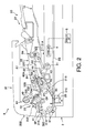
- Fig. 2 is an enlarged cross-sectional side view of a document feeder unit in the embodiment according to one or more aspects of the present invention.
- Fig. 3A and 3B illustrate operations in a double-side scanning mode in the embodiment according to one or more aspects of the present invention.
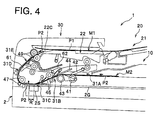
- Fig. 4 illustrates an operation in a single-side scanning mode in the embodiment according to one or more aspects of the present invention.
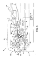
- Fig. 5 shows a state where a document sheet jams within a reversal path in the embodiment according to one or more aspects of the present invention.
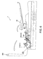
- Fig. 6 illustrates a method for settling a jam in the embodiment according to one or more aspects of the present invention.
- a "carrying direction” represents a direction in which a document sheet is conveyed from a feed tray 10 to a catch tray 20 (a direction indicated by bold arrows in Fig. 1 ).
- a “discharging direction” represents a direction in which a document sheet is ejected from a document feeder unit 30 to the catch tray 20.
- an upstream side and a downstream side in the carrying direction and the discharging direction will simply be referred to as an "upstream side” and a “downstream side,” respectively.
- a direction perpendicular to the carrying direction and the discharging direction (namely, a direction perpendicular to Fig. 1 ) will be referred to as a "width direction.”
- a document scanning device 1 includes a flatbed scanner 2 with a known configuration, a document feeder 3 configured to convey a document sheet to a scanning position R, a controller 4 configured to control an operation of scanning the document sheet, and an operation unit 5 configured to accept a user input therethrough.
- the flatbed scanner 2 disposed at a lower side of the document scanning device 1, includes a platen glass 2G on which a document sheet is statically placed and an image sensor 2S.
- the flatbed scanner 2 is configured to scan, with the image sensor 2S, a document sheet statically placed on the platen glass 2G as well as a document sheet conveyed into the scanning position R.
- the document feeder 3 is a device adapted to convey a document sheet to the scanning position R and to scan one side or both sides of the document sheet.
- the document feeder 3 is provided above the flatbed scanner 2 in a manner openable and closable relative to the platen glass 2G.
- the document feeder 3 includes the feed tray 10 on which document sheets are placed, the catch tray 20 onto which the document sheets are ejected, and the document feeder unit 30.
- the catch tray 20, provided above the feed tray 10, includes a fixed tray 21 and a flap 22 disposed upstream relative to the fixed tray 21.
- the fixed tray 21 is fixed to a main body frame 30A constituting an outer frame of the document feeder unit 30, so as not to move relative to the document feeder unit 30.
- An upper portion of the main body frame 30A is configured as a cover 30B which is formed in an L-shape in a cross-sectional side view as illustrated in Fig. 1 . Further, the cover 30B is configured to be turned up around a rotational shaft 30C provided at a lower left end in Fig. 1 . Thereby, part of a below-mentioned carrying path 31 is rendered open to the upper outside (see Fig. 6 ).
- the flap 22 is supported by the main body frame 30A of the document feeder 3, swingably in the vertical direction relative to the fixed tray around a swing shaft 22A that is provided at a downstream side of the flap 22.
- the flap 22 has a bending portion 22C formed to bend downward, at an upstream distal end of the flap 22.
- a cam 24 engages with an upstream distal end portion of the flap 22 of the flap 22.
- the cam 24 includes a pushing-up bar 24A that is provided below the flap 22 so as to extend over between both ends of the flap 22 in the width direction, two shafts 24B provided at both sides of the flap 22 in the width direction, and a joint 24C configured to connect both ends of the pushing-up bar 24A in the width direction with the shafts 24B, respectively.
- Each of the shafts 24B is pivotably supported by the main body frame 30A.
- the cam 24 is configured to swing the flap 22 between a lower position as shown in Fig. 1 and an upper position as shown in Fig. 5 when rotated clockwise or counterclockwise by a driving mechanism (not shown) controlled by the controller 4. Thereby, an ejection mode to eject document sheets is switched between below-mentioned two modes of a stacking ejection mode and an inserting ejection mode.
- the flap 22 when the flap 22 is lifted up manually by the user in the state where the document feeder 3 is not in use, the flap 22 can be swung higher than shown in Fig. 4 . Thereby, part of a below-mentioned reversal path 32 is rendered open to the upper outside (see Fig. 6 ).
- the swing shaft 22A of the flap 22 is disposed farther away from the ejection rollers 49 than below-mentioned switchback rollers 53. Thereby, all the section between the switchback rollers 53 and below-mentioned chute member 70 is rendered open.
- the document feeder unit 30 includes a carrying path 31 formed to guide a document sheet from the feed tray 10 to the catch tray 20 and a reversal path 32 formed to switchback the document sheet.
- the carrying path 31 includes a suction path 31 A formed to extend substantially horizontally from the feed tray 10, an oblique path 3 1 B formed to extend obliquely downward from the suction path 31A, a horizontal path 31C formed to extend substantially horizontally from the oblique path 31B, a curved path 31D formed to extend in the shape of an arc upward from the horizontal path 31C, and an ejection path 31E formed to extend obliquely upward from the curved path 31D to the catch tray 20 (outside the carrying path 31).
- a lower side of the horizontal path 31C corresponds to the scanning position R adapted to face the image sensor 2S across the platen glass 2G.
- the feeding mechanism On the carrying path 31, there is a feeding mechanism provided to feed a document sheet from the feed tray 10 to the catch tray 20 via the scanning position R.
- the feeding mechanism includes a pickup roller 41, a pickup nipper 42, a separation roller 43, and a separation nipper 44, which are provided on the suction path 31A.
- the feeding mechanism further includes first feed rollers 45 provided on the oblique path 31B, second feed rollers 47 provided on the curved path 31D, and ejection rollers 49 provided on the ejection path 31E.
- the pickup roller 41 and the pickup nipper 42 are configured to make document sheets placed on the feed tray 10 approach to the separation roller 43.
- the separation roller 43 and the separation nipper 44 are configured to separate the document sheets fed by the pickup roller 41 and the pickup nipper 42 and to convey the document sheets to the scanning position R separately on a sheet-by-sheet basis.
- the first feed rollers 45 and the second feed rollers 47 are configured to feed the document sheets on the carrying path 31.
- the ejection rollers 49 are configured to eject onto the catch tray 20 the document sheets that have completely been scanned.
- the reversal path 32 includes a first reversal path 32A and a second reversal path 32B.
- the first reversal path 32A is configured to guide part (substantially all) of a document sheet to the outside of the document feeder unit 30 in a switchback operation.
- the second reversal path 32B is configured to, after the switchback operation, again guide the document sheet to the scanning position R.
- the first reversal path 32A is formed to diverge from the carrying path 31 at a diverging point SP on a downstream side relative to the scanning position R (i.e., at a downstream end of the curved path 31D) and to extend toward the outside (rightward in Fig. 2 ).
- the first reversal path 32A includes an S-shaped formed with an upward-convex curved section extending from the diverging point SP and a downward-convex curved section following the upward-convex curved section.
- the first reversal path 32A has an upper guide surface which is formed with a lower surface 61A of a first guide member 61 (indicated by a solid line in Fig.
- the first reversal path 32A has a lower guide surface which is formed with an upper surface A1 of the main body frame 30A and an upper surface of the second guide member 62 (indicated by a solid line in Fig. 2 ).
- the lower surface 22D of the flap 22 constitutes part of an upper wall of the first reversal path 32A.
- the chute member 70 is disposed below a distal end of the flap 22 and provided with a guide portion 71 that is disposed downstream relative to below-mentioned third feed rollers 51.
- the guide portion 71 constitutes part of the upper wall of the first reversal path 32A.
- most of the upper wall of the first reversal oath 32A is formed with the guide portion 71 and part of the flap 22 that are aligned side by side.
- the second reversal path 32B is configured to diverge from substantially a center of the first reversal path 32A and extend obliquely down toward the oblique path 31B i.e., toward an upstream side relative to the scanning position R).
- a reversal mechanism is provided, which is configured to feed and guide a document sheet in the switchback operation.
- the reversal mechanism includes third feed rollers 51 that serve as subsidiary rollers to feed a document sheet and switchback rollers 53, a first guide member 61 provided at a diverging portion between the curved path 31D and the first reversal path 32A, and a second guide member 62 provided at a diverging portion between the first reversal path 32A and the second reversal path 32B.
- the third feed rollers 51 are configured to feed a document sheet toward the outside, and disposed upstream relative to an apex PP of the downward-convex curved section of the S-shaped first reversal path 32A. More specifically, the third feed rollers 51 are disposed upstream relative to an inflection point CP (between the upward-convex curved section and the downward-convex curved section) of the S-shaped first reversal path 32A.
- the switchback rollers 53 are disposed at a downstream end of the first reversal path 32A, and configured to switchback a document sheet (i.e., reverse a traveling direction of the conveyed document sheet with a previous trailing end of the document sheet as a new leading end thereof).
- the first guide member 61 is configured to be swung up and down.
- the first guide member 61 constitutes a lower guide surface of the ejection path 31E.
- the first guide member 61 constitutes an upper guide surface of the first reversal path 32A, so as to guide a document sheet to the reversal path 32.
- the second guide member 62 is configured to be swung up and down.
- the second guide member 62 constitutes a lower guide surface of the first reversal path 32A, so as to guide a document sheet to the outside.
- the second guide member 62 constitutes an upper guide surface of the second reversal path 32B, so as to guide a document sheet from the first reversal path 32A to the second reversal path 32B.
- the controller 4 is provided with a CPU, a RAM, a ROM, and an input/output circuit (which are not shown), and placed in an adequate position within the document scanning device 1.
- the controller 4 is configured to, based on programs and data stored on the ROM, or outputs from the operation unit, take control for driving the feeding mechanism, the reversal mechanism, and the image sensor 2S. Thus, the controller 4 takes control of an operation of scanning document sheets.
- the operation unit 5 is configured with a plurality of operation buttons (see Fig. 1 ).
- the user can input an instruction to start document scanning (that is, an instruction to start document feeding for the document feeder 3) or select either a single-side scanning mode (an inserting ejection mode) or a double-side scanning mode (a stacking ejection mode).
- a document sheet M2 is set on the feed tray 10 with a first scanned surface P3 down and a second scanned surface P4 up. Additionally, when the user operates the operation unit 5 and selects the double-side scanning mode, the flap 22 swings down, the first guide member 61 swings up, and the second guide member 62 swings down.
- the document sheet M2 on the feed tray 10 is conveyed to the scanning position R by the separation roller 43 and the first feed rollers 45, and then the first scanned surface P3 is scanned. Thereafter, the document sheet M2 is conveyed on the curved path 31D by the second feed rollers 47, and fed along a lower surface of the first guide member 61 into the first reversal path 32A. At this time, the document sheet M2 is with the first scanned surface P3 up and the second scanned surface P4 down. Thereafter, the document sheet M2 is conveyed, by the third feed rollers 51, on the first reversal path 32A toward the outside.
- the document sheet M2 to which a traveling force is given by the third feed rollers 51, is conveyed toward the outside in a preferable manner, without jamming at the apex PP of the downward-convex curved section of the S-shaped first reversal path 32A.
- the switchback rollers 53 are temporarily stopped by a known control technique.
- the first guide member 61 swings down and the second guide member 62 swings up such that the path of the document sheet M2 is switched.
- the document sheet M2 is pulled back to the first reversal path 32A, and then fed along a lower surface of the second guide member 62 into the second reversal path 32B.
- the document sheet M2 is conveyed again to the oblique path 31B, and fed to the scanning position R by the first feed rollers 45 such that the second scanned surface P4 is scanned.
- the document sheet M2 is conveyed on the curved path 31D and the ejection path 31E by the second feed rollers 47 and the ejection rollers 49, and then ejected onto the catch tray 20 with the first scanned surface P3 down and the second scanned surface P4 up.
- the bending portion 22C of the flap 22 is located below the ejection rollers 49. Therefore, a trailing end of an already-ejected document sheet M1 loaded on the bending portion 22C is located lower than the ejection rollers 49. Thereby, the later-ejected document sheet M2 is placed onto the already-ejected document sheet M1 on the catch tray 20.
- the ejection mode at this time is referred to as the stacking ejection mode.
- document sheets are sequentially ejected on a stack of document sheets that have already been ejected with the first scanned surfaces thereof down and the second scanned surfaces thereof up. Therefore, the document sheets M1 and M2 are aligned in the order of pages P1, P2, P3, and P4 from the bottom. The order of the pages is the same as when the documents M1 and M2 are placed on the feed tray 10.
- the document sheet M2 is set on the feed tray 10 with the scanned surface P2 down. Further, when the user selects the single-side scanning mode through the operation unit 5, the flap 22 swings up and the first guide member 61 swings down.
- the document sheet M2 on the feed tray 10 is conveyed to the scanning position R by the separation roller 43 and the first feed rollers 45, and then the scanned surface P2 is scanned. Thereafter, the document sheet M2 is fed on the curved path 31D and the ejection path 31E by the second feed rollers 47 and the ejection rollers 49, and then ejected onto the catch tray 20 with the scanned surface P2 up.
- the bending portion 22C of the flap 22 is located above a position where the two ejection rollers 49 nip a sheet. Therefore, a trailing end, placed on the flap 22, of the already-ejected document sheet M1 is located above the position where the two ejection rollers 49 nip a sheet. Thereby, the later-ejected document sheet M2 establishes contact, from beneath, with the trailing end of the already-ejected document sheet M1 on the catch tray 20, and then is ejected in a manner inserted under the document sheet M1.
- the ejection mode at this time is referred to as the inserting ejection mode.
- document sheets are sequentially ejected in a manner inserted under a stack of already-ejected document sheets, with the scanned surfaces up. Therefore, the document sheets M1 and M2 are aligned in the order of the pages P1 and P2 from the top.
- the order of the pages is the same as when the document sheets M1 and M2 are placed on the feed tray 10.
- a short document sheet M3 such as a postcard is conveyed from the switchback rollers 53 to the scanning position R, the document sheet M3 is jammed at the first feed rollers 45.
- the document sheet M3 is entirely within the reversal path 32, and might not be removed by an external user operation.
- part of the reversal path 32 is rendered open to the upper outside such that the document sheet M3 jammed can be exposed to the outside. Therefore, by manually pulling the document sheet M3 exposed to the outside, the user can easily remove the document sheet M3.
- the ejection mode can be switched between the stacking ejection mode and the inserting ejection mode by swinging the flap 22 up and down. Therefore, in the single-side scanning, document sheets can be aligned in order of page from the top in the inserting ejection mode. Further, in the double-side scanning, document sheets can be aligned in order of page from the bottom in the stacking ejection mode. Since the document alignment order is switched by swinging the flap 22 up and down, the single catch tray 20 onto which document sheets are ejected has only to be provided above the feed tray 10. Hence, compared with a known configuration in which an additional catch tray is provided beside a scanning position, the document feeder 3 can relatively be downsized. Moreover, since the flap 22 constitutes part of the reversal path 32, the document feeder 3 can be more downsized than a configuration in which a specific component is provided to constitute the reversal path 32.
- the third feed rollers 51 are provided upstream relative to the apex PP of the downward-convex curved section of the S-shaped first reversal path 32A. Therefore, even though the leading end of the document sheet nearly gets stacked in the vicinity of the apex PP of the flexural section, the document sheet is forcibly pushed by the third feed rollers 51 and the leading end of the document sheet can proceed. Hence, it is possible to prevent a jam from occurring within the first reversal path 32A. Further, in the embodiment, the third feed rollers 51 are provided upstream relative to the inflection point CP of the S-shaped first reversal path 32A.
- the chute member 70 is disposed downstream relative to the third feed rollers 51, below the distal end of the flap 22. Therefore, when a document sheet pushed out of the third feed rollers 51 is conveyed while pushing up the distal end of the flap 22, the chute member 70 can prevent the document sheet from straying from the first reversal path 32A.
- the swingable cover 30B constitutes the ejection path 31E, even though a document sheet (a short sheet such as a postcard) jams within the ejection path 31E, the user can easily remove the document sheet by opening the cover 30B.
- a document sheet a short sheet such as a postcard
- the third feed rollers 51 are disposed upstream relative to the inflection point CP of the S-shaped first reversal path 32A.
- the third feed rollers 51 may be placed at the inflection point CP.
- the flap 22 is configured to swing.
- the flap 22 may be configured to slide up and down.
- the mechanism for switching the ejection mode is configured with the flap 22 and the cam 24.
- a flap which is configured to be swung up and down by a driving force transmitted to a swing shaft thereof, may be provided to switch the ejection mode.
Landscapes
- Engineering & Computer Science (AREA)
- Multimedia (AREA)
- Signal Processing (AREA)
- Mechanical Engineering (AREA)
- Physics & Mathematics (AREA)
- General Physics & Mathematics (AREA)
- Separation, Sorting, Adjustment, Or Bending Of Sheets To Be Conveyed (AREA)
- Facsimiles In General (AREA)
- Exposure Or Original Feeding In Electrophotography (AREA)
- Controlling Sheets Or Webs (AREA)
- Pile Receivers (AREA)
- Facsimile Scanning Arrangements (AREA)
Applications Claiming Priority (1)
| Application Number | Priority Date | Filing Date | Title |
|---|---|---|---|
| JP2008247707A JP4623186B2 (ja) | 2008-09-26 | 2008-09-26 | 原稿搬送装置 |
Publications (3)
| Publication Number | Publication Date |
|---|---|
| EP2177464A2 true EP2177464A2 (de) | 2010-04-21 |
| EP2177464A3 EP2177464A3 (de) | 2012-02-08 |
| EP2177464B1 EP2177464B1 (de) | 2016-05-11 |
Family
ID=41566153
Family Applications (1)
| Application Number | Title | Priority Date | Filing Date |
|---|---|---|---|
| EP09170934.5A Not-in-force EP2177464B1 (de) | 2008-09-26 | 2009-09-22 | Dokumentzuführer und Dokumentabtastvorrichtung damit |
Country Status (4)
| Country | Link |
|---|---|
| US (1) | US8295757B2 (de) |
| EP (1) | EP2177464B1 (de) |
| JP (1) | JP4623186B2 (de) |
| CN (1) | CN101686300B (de) |
Families Citing this family (8)
| Publication number | Priority date | Publication date | Assignee | Title |
|---|---|---|---|---|
| JP4623187B2 (ja) * | 2008-09-26 | 2011-02-02 | ブラザー工業株式会社 | 原稿搬送装置 |
| JP5754625B2 (ja) * | 2011-03-18 | 2015-07-29 | 株式会社リコー | 画像読取装置および画像形成装置 |
| JP6237420B2 (ja) * | 2014-03-31 | 2017-11-29 | ブラザー工業株式会社 | 画像記録装置 |
| JP6314962B2 (ja) * | 2015-11-24 | 2018-04-25 | コニカミノルタ株式会社 | 両面画像読取装置および画像形成装置 |
| CN105775883B (zh) * | 2016-02-26 | 2018-04-06 | 深圳怡化电脑股份有限公司 | 一种纸文件回收的装置及方法 |
| JP7423983B2 (ja) * | 2019-10-30 | 2024-01-30 | セイコーエプソン株式会社 | 記録装置 |
| EP4188859B1 (de) * | 2020-08-03 | 2024-12-04 | Bobst Mex Sa | Transfermodul für eine verarbeitungsmaschine |
| JP2024076723A (ja) * | 2022-11-25 | 2024-06-06 | セイコーエプソン株式会社 | 媒体処理装置、記録システム、媒体処理装置の制御方法 |
Family Cites Families (16)
| Publication number | Priority date | Publication date | Assignee | Title |
|---|---|---|---|---|
| JPS6326661U (de) * | 1986-08-04 | 1988-02-22 | ||
| JPH04106064A (ja) * | 1990-08-22 | 1992-04-08 | Oki Electric Ind Co Ltd | 記録装置における記録媒体排出方法 |
| JPH08310740A (ja) | 1995-03-10 | 1996-11-26 | Ricoh Co Ltd | シートスルースキャナー両面原稿自動送り装置 |
| US5791645A (en) | 1995-03-10 | 1998-08-11 | Ricoh Company, Ltd. | Simple inverting path for an auto document feeder for an image forming apparatus |
| JPH08282897A (ja) | 1995-04-13 | 1996-10-29 | Matsushita Electric Ind Co Ltd | 自動原稿送り装置 |
| US6095517A (en) * | 1998-10-02 | 2000-08-01 | Xerox Corporation | 1-N and N-1 cut sheet receiving and stacking apparatus |
| JP2001106408A (ja) * | 1999-10-05 | 2001-04-17 | Sharp Corp | シート体排出装置及びシート体排出方法 |
| JP2003078705A (ja) * | 2001-09-03 | 2003-03-14 | Konica Corp | 画像形成装置 |
| JP4075788B2 (ja) * | 2003-12-05 | 2008-04-16 | 村田機械株式会社 | 自動原稿搬送装置 |
| KR100694089B1 (ko) * | 2005-02-01 | 2007-03-12 | 삼성전자주식회사 | 원고배지 카세트, 이를 구비한 이미지 스캐너, 및 원고스캔 방법 |
| JP2006232460A (ja) * | 2005-02-24 | 2006-09-07 | Ricoh Co Ltd | 原稿自動送り装置 |
| US20070003344A1 (en) * | 2005-06-29 | 2007-01-04 | Samsung Electronics Co., Ltd. | Duplex automatic document feeding apparatus and a duplex document feeding method |
| JP4165544B2 (ja) * | 2005-09-26 | 2008-10-15 | ブラザー工業株式会社 | シート材搬送装置 |
| JP2007238252A (ja) * | 2006-03-07 | 2007-09-20 | Brother Ind Ltd | シート搬送装置、画像読取装置 |
| JP4321608B2 (ja) * | 2007-02-28 | 2009-08-26 | ブラザー工業株式会社 | シート搬送装置及び画像読取装置。 |
| JP4492714B2 (ja) * | 2008-02-29 | 2010-06-30 | ブラザー工業株式会社 | 原稿搬送装置 |
-
2008
- 2008-09-26 JP JP2008247707A patent/JP4623186B2/ja not_active Expired - Fee Related
-
2009
- 2009-09-22 EP EP09170934.5A patent/EP2177464B1/de not_active Not-in-force
- 2009-09-25 US US12/566,864 patent/US8295757B2/en not_active Expired - Fee Related
- 2009-09-27 CN CN2009101793866A patent/CN101686300B/zh not_active Expired - Fee Related
Also Published As
| Publication number | Publication date |
|---|---|
| EP2177464A3 (de) | 2012-02-08 |
| US20100080639A1 (en) | 2010-04-01 |
| CN101686300A (zh) | 2010-03-31 |
| US8295757B2 (en) | 2012-10-23 |
| EP2177464B1 (de) | 2016-05-11 |
| JP2010076896A (ja) | 2010-04-08 |
| JP4623186B2 (ja) | 2011-02-02 |
| CN101686300B (zh) | 2011-12-21 |
Similar Documents
| Publication | Publication Date | Title |
|---|---|---|
| EP2177464B1 (de) | Dokumentzuführer und Dokumentabtastvorrichtung damit | |
| JP3685994B2 (ja) | シート後処理装置 | |
| JP4569675B2 (ja) | 原稿搬送装置 | |
| US8289589B2 (en) | Document scanning device | |
| JP4384010B2 (ja) | シート搬送装置及び画像形成装置 | |
| US20070228646A1 (en) | Sheet conveyance apparatus, sheet processing apparatus, and image forming apparatus | |
| JP4600534B2 (ja) | 原稿搬送装置 | |
| CN101388938A (zh) | 自动原稿读取装置 | |
| EP2096065B1 (de) | Dokumentenzuführungsvorrichtung | |
| US7764920B2 (en) | Duplex document feeder | |
| CN101631179A (zh) | 自动原稿输送装置、图像扫描装置以及原稿输送方法 | |
| JP4569674B2 (ja) | 原稿搬送装置 | |
| CN106911875A (zh) | 原稿输送装置、原稿读取装置和图像形成装置 | |
| JP2013040015A (ja) | 用紙処理装置及び画像形成システム | |
| JP5760725B2 (ja) | 用紙処理装置及び画像形成システム | |
| JP3724791B2 (ja) | 原稿搬送装置及び画像読取装置 | |
| JP4278153B2 (ja) | 用紙反転装置及び画像形成装置 | |
| US20100080640A1 (en) | Document Feeder and Document Scanning Device Provided with the Same | |
| EP2096064B1 (de) | Dokumentenzuführungsvorrichtung | |
| JP2011173716A (ja) | 原稿搬送装置 | |
| JP2006056682A (ja) | 用紙反転装置及び該用紙反転装置を備えた画像形成装置 | |
| JP2002356267A (ja) | シート排出装置および画像形成装置 | |
| JP4435643B2 (ja) | シート材搬送装置、原稿搬送装置、原稿読取装置、及びこれらを用いた画像形成装置 | |
| JP2010202338A (ja) | 用紙処理装置、画像形成装置、用紙の排紙制御方法、及び排紙制御プログラム | |
| JP2020132333A (ja) | シート搬送装置 |
Legal Events
| Date | Code | Title | Description |
|---|---|---|---|
| PUAI | Public reference made under article 153(3) epc to a published international application that has entered the european phase |
Free format text: ORIGINAL CODE: 0009012 |
|
| AK | Designated contracting states |
Kind code of ref document: A2 Designated state(s): AT BE BG CH CY CZ DE DK EE ES FI FR GB GR HR HU IE IS IT LI LT LU LV MC MK MT NL NO PL PT RO SE SI SK SM TR |
|
| PUAL | Search report despatched |
Free format text: ORIGINAL CODE: 0009013 |
|
| AK | Designated contracting states |
Kind code of ref document: A3 Designated state(s): AT BE BG CH CY CZ DE DK EE ES FI FR GB GR HR HU IE IS IT LI LT LU LV MC MK MT NL NO PL PT RO SE SI SK SM TR |
|
| RIC1 | Information provided on ipc code assigned before grant |
Ipc: G03G 15/00 20060101ALI20120104BHEP Ipc: H04N 1/00 20060101ALI20120104BHEP Ipc: B65H 31/02 20060101ALI20120104BHEP Ipc: B65H 29/14 20060101AFI20120104BHEP Ipc: B65H 29/60 20060101ALI20120104BHEP |
|
| 17P | Request for examination filed |
Effective date: 20120413 |
|
| GRAP | Despatch of communication of intention to grant a patent |
Free format text: ORIGINAL CODE: EPIDOSNIGR1 |
|
| INTG | Intention to grant announced |
Effective date: 20160225 |
|
| GRAS | Grant fee paid |
Free format text: ORIGINAL CODE: EPIDOSNIGR3 |
|
| GRAA | (expected) grant |
Free format text: ORIGINAL CODE: 0009210 |
|
| AK | Designated contracting states |
Kind code of ref document: B1 Designated state(s): AT BE BG CH CY CZ DE DK EE ES FI FR GB GR HR HU IE IS IT LI LT LU LV MC MK MT NL NO PL PT RO SE SI SK SM TR |
|
| REG | Reference to a national code |
Ref country code: GB Ref legal event code: FG4D |
|
| RIN1 | Information on inventor provided before grant (corrected) |
Inventor name: MATSUSHIMA, RYOICHI |
|
| REG | Reference to a national code |
Ref country code: CH Ref legal event code: EP |
|
| REG | Reference to a national code |
Ref country code: AT Ref legal event code: REF Ref document number: 798491 Country of ref document: AT Kind code of ref document: T Effective date: 20160515 |
|
| REG | Reference to a national code |
Ref country code: IE Ref legal event code: FG4D |
|
| REG | Reference to a national code |
Ref country code: DE Ref legal event code: R096 Ref document number: 602009038562 Country of ref document: DE |
|
| REG | Reference to a national code |
Ref country code: LT Ref legal event code: MG4D |
|
| REG | Reference to a national code |
Ref country code: NL Ref legal event code: MP Effective date: 20160511 |
|
| REG | Reference to a national code |
Ref country code: FR Ref legal event code: PLFP Year of fee payment: 8 |
|
| PG25 | Lapsed in a contracting state [announced via postgrant information from national office to epo] |
Ref country code: NO Free format text: LAPSE BECAUSE OF FAILURE TO SUBMIT A TRANSLATION OF THE DESCRIPTION OR TO PAY THE FEE WITHIN THE PRESCRIBED TIME-LIMIT Effective date: 20160811 Ref country code: NL Free format text: LAPSE BECAUSE OF FAILURE TO SUBMIT A TRANSLATION OF THE DESCRIPTION OR TO PAY THE FEE WITHIN THE PRESCRIBED TIME-LIMIT Effective date: 20160511 Ref country code: LT Free format text: LAPSE BECAUSE OF FAILURE TO SUBMIT A TRANSLATION OF THE DESCRIPTION OR TO PAY THE FEE WITHIN THE PRESCRIBED TIME-LIMIT Effective date: 20160511 Ref country code: FI Free format text: LAPSE BECAUSE OF FAILURE TO SUBMIT A TRANSLATION OF THE DESCRIPTION OR TO PAY THE FEE WITHIN THE PRESCRIBED TIME-LIMIT Effective date: 20160511 |
|
| REG | Reference to a national code |
Ref country code: AT Ref legal event code: MK05 Ref document number: 798491 Country of ref document: AT Kind code of ref document: T Effective date: 20160511 |
|
| PG25 | Lapsed in a contracting state [announced via postgrant information from national office to epo] |
Ref country code: SE Free format text: LAPSE BECAUSE OF FAILURE TO SUBMIT A TRANSLATION OF THE DESCRIPTION OR TO PAY THE FEE WITHIN THE PRESCRIBED TIME-LIMIT Effective date: 20160511 Ref country code: PT Free format text: LAPSE BECAUSE OF FAILURE TO SUBMIT A TRANSLATION OF THE DESCRIPTION OR TO PAY THE FEE WITHIN THE PRESCRIBED TIME-LIMIT Effective date: 20160912 Ref country code: ES Free format text: LAPSE BECAUSE OF FAILURE TO SUBMIT A TRANSLATION OF THE DESCRIPTION OR TO PAY THE FEE WITHIN THE PRESCRIBED TIME-LIMIT Effective date: 20160511 Ref country code: HR Free format text: LAPSE BECAUSE OF FAILURE TO SUBMIT A TRANSLATION OF THE DESCRIPTION OR TO PAY THE FEE WITHIN THE PRESCRIBED TIME-LIMIT Effective date: 20160511 Ref country code: GR Free format text: LAPSE BECAUSE OF FAILURE TO SUBMIT A TRANSLATION OF THE DESCRIPTION OR TO PAY THE FEE WITHIN THE PRESCRIBED TIME-LIMIT Effective date: 20160812 Ref country code: LV Free format text: LAPSE BECAUSE OF FAILURE TO SUBMIT A TRANSLATION OF THE DESCRIPTION OR TO PAY THE FEE WITHIN THE PRESCRIBED TIME-LIMIT Effective date: 20160511 |
|
| PG25 | Lapsed in a contracting state [announced via postgrant information from national office to epo] |
Ref country code: IT Free format text: LAPSE BECAUSE OF FAILURE TO SUBMIT A TRANSLATION OF THE DESCRIPTION OR TO PAY THE FEE WITHIN THE PRESCRIBED TIME-LIMIT Effective date: 20160511 |
|
| PG25 | Lapsed in a contracting state [announced via postgrant information from national office to epo] |
Ref country code: CZ Free format text: LAPSE BECAUSE OF FAILURE TO SUBMIT A TRANSLATION OF THE DESCRIPTION OR TO PAY THE FEE WITHIN THE PRESCRIBED TIME-LIMIT Effective date: 20160511 Ref country code: SK Free format text: LAPSE BECAUSE OF FAILURE TO SUBMIT A TRANSLATION OF THE DESCRIPTION OR TO PAY THE FEE WITHIN THE PRESCRIBED TIME-LIMIT Effective date: 20160511 Ref country code: RO Free format text: LAPSE BECAUSE OF FAILURE TO SUBMIT A TRANSLATION OF THE DESCRIPTION OR TO PAY THE FEE WITHIN THE PRESCRIBED TIME-LIMIT Effective date: 20160511 Ref country code: DK Free format text: LAPSE BECAUSE OF FAILURE TO SUBMIT A TRANSLATION OF THE DESCRIPTION OR TO PAY THE FEE WITHIN THE PRESCRIBED TIME-LIMIT Effective date: 20160511 Ref country code: EE Free format text: LAPSE BECAUSE OF FAILURE TO SUBMIT A TRANSLATION OF THE DESCRIPTION OR TO PAY THE FEE WITHIN THE PRESCRIBED TIME-LIMIT Effective date: 20160511 |
|
| REG | Reference to a national code |
Ref country code: DE Ref legal event code: R097 Ref document number: 602009038562 Country of ref document: DE |
|
| PG25 | Lapsed in a contracting state [announced via postgrant information from national office to epo] |
Ref country code: SM Free format text: LAPSE BECAUSE OF FAILURE TO SUBMIT A TRANSLATION OF THE DESCRIPTION OR TO PAY THE FEE WITHIN THE PRESCRIBED TIME-LIMIT Effective date: 20160511 Ref country code: AT Free format text: LAPSE BECAUSE OF FAILURE TO SUBMIT A TRANSLATION OF THE DESCRIPTION OR TO PAY THE FEE WITHIN THE PRESCRIBED TIME-LIMIT Effective date: 20160511 Ref country code: PL Free format text: LAPSE BECAUSE OF FAILURE TO SUBMIT A TRANSLATION OF THE DESCRIPTION OR TO PAY THE FEE WITHIN THE PRESCRIBED TIME-LIMIT Effective date: 20160511 Ref country code: BE Free format text: LAPSE BECAUSE OF NON-PAYMENT OF DUE FEES Effective date: 20160511 |
|
| PLBE | No opposition filed within time limit |
Free format text: ORIGINAL CODE: 0009261 |
|
| STAA | Information on the status of an ep patent application or granted ep patent |
Free format text: STATUS: NO OPPOSITION FILED WITHIN TIME LIMIT |
|
| 26N | No opposition filed |
Effective date: 20170214 |
|
| PG25 | Lapsed in a contracting state [announced via postgrant information from national office to epo] |
Ref country code: MC Free format text: LAPSE BECAUSE OF FAILURE TO SUBMIT A TRANSLATION OF THE DESCRIPTION OR TO PAY THE FEE WITHIN THE PRESCRIBED TIME-LIMIT Effective date: 20160511 |
|
| REG | Reference to a national code |
Ref country code: CH Ref legal event code: PL |
|
| PG25 | Lapsed in a contracting state [announced via postgrant information from national office to epo] |
Ref country code: SI Free format text: LAPSE BECAUSE OF FAILURE TO SUBMIT A TRANSLATION OF THE DESCRIPTION OR TO PAY THE FEE WITHIN THE PRESCRIBED TIME-LIMIT Effective date: 20160511 |
|
| REG | Reference to a national code |
Ref country code: IE Ref legal event code: MM4A |
|
| PG25 | Lapsed in a contracting state [announced via postgrant information from national office to epo] |
Ref country code: IE Free format text: LAPSE BECAUSE OF NON-PAYMENT OF DUE FEES Effective date: 20160922 Ref country code: CH Free format text: LAPSE BECAUSE OF NON-PAYMENT OF DUE FEES Effective date: 20160930 Ref country code: LI Free format text: LAPSE BECAUSE OF NON-PAYMENT OF DUE FEES Effective date: 20160930 |
|
| REG | Reference to a national code |
Ref country code: FR Ref legal event code: PLFP Year of fee payment: 9 |
|
| PG25 | Lapsed in a contracting state [announced via postgrant information from national office to epo] |
Ref country code: LU Free format text: LAPSE BECAUSE OF NON-PAYMENT OF DUE FEES Effective date: 20160922 |
|
| PG25 | Lapsed in a contracting state [announced via postgrant information from national office to epo] |
Ref country code: HU Free format text: LAPSE BECAUSE OF FAILURE TO SUBMIT A TRANSLATION OF THE DESCRIPTION OR TO PAY THE FEE WITHIN THE PRESCRIBED TIME-LIMIT; INVALID AB INITIO Effective date: 20090922 Ref country code: CY Free format text: LAPSE BECAUSE OF FAILURE TO SUBMIT A TRANSLATION OF THE DESCRIPTION OR TO PAY THE FEE WITHIN THE PRESCRIBED TIME-LIMIT Effective date: 20160511 |
|
| PG25 | Lapsed in a contracting state [announced via postgrant information from national office to epo] |
Ref country code: MK Free format text: LAPSE BECAUSE OF FAILURE TO SUBMIT A TRANSLATION OF THE DESCRIPTION OR TO PAY THE FEE WITHIN THE PRESCRIBED TIME-LIMIT Effective date: 20160511 Ref country code: IS Free format text: LAPSE BECAUSE OF FAILURE TO SUBMIT A TRANSLATION OF THE DESCRIPTION OR TO PAY THE FEE WITHIN THE PRESCRIBED TIME-LIMIT Effective date: 20160511 Ref country code: TR Free format text: LAPSE BECAUSE OF FAILURE TO SUBMIT A TRANSLATION OF THE DESCRIPTION OR TO PAY THE FEE WITHIN THE PRESCRIBED TIME-LIMIT Effective date: 20160511 Ref country code: MT Free format text: LAPSE BECAUSE OF NON-PAYMENT OF DUE FEES Effective date: 20160930 |
|
| PG25 | Lapsed in a contracting state [announced via postgrant information from national office to epo] |
Ref country code: BG Free format text: LAPSE BECAUSE OF FAILURE TO SUBMIT A TRANSLATION OF THE DESCRIPTION OR TO PAY THE FEE WITHIN THE PRESCRIBED TIME-LIMIT Effective date: 20160511 |
|
| REG | Reference to a national code |
Ref country code: FR Ref legal event code: PLFP Year of fee payment: 10 |
|
| PGFP | Annual fee paid to national office [announced via postgrant information from national office to epo] |
Ref country code: GB Payment date: 20220810 Year of fee payment: 14 Ref country code: DE Payment date: 20220615 Year of fee payment: 14 |
|
| PGFP | Annual fee paid to national office [announced via postgrant information from national office to epo] |
Ref country code: FR Payment date: 20220810 Year of fee payment: 14 |
|
| REG | Reference to a national code |
Ref country code: DE Ref legal event code: R119 Ref document number: 602009038562 Country of ref document: DE |
|
| GBPC | Gb: european patent ceased through non-payment of renewal fee |
Effective date: 20230922 |
|
| PG25 | Lapsed in a contracting state [announced via postgrant information from national office to epo] |
Ref country code: GB Free format text: LAPSE BECAUSE OF NON-PAYMENT OF DUE FEES Effective date: 20230922 |
|
| PG25 | Lapsed in a contracting state [announced via postgrant information from national office to epo] |
Ref country code: GB Free format text: LAPSE BECAUSE OF NON-PAYMENT OF DUE FEES Effective date: 20230922 Ref country code: FR Free format text: LAPSE BECAUSE OF NON-PAYMENT OF DUE FEES Effective date: 20230930 Ref country code: DE Free format text: LAPSE BECAUSE OF NON-PAYMENT OF DUE FEES Effective date: 20240403 |