EP2177289B1 - Machines-outils et procédé destinés à l'évacuation d'une partie d'une pièce à usiner - Google Patents
Machines-outils et procédé destinés à l'évacuation d'une partie d'une pièce à usiner Download PDFInfo
- Publication number
- EP2177289B1 EP2177289B1 EP20080018301 EP08018301A EP2177289B1 EP 2177289 B1 EP2177289 B1 EP 2177289B1 EP 20080018301 EP20080018301 EP 20080018301 EP 08018301 A EP08018301 A EP 08018301A EP 2177289 B1 EP2177289 B1 EP 2177289B1
- Authority
- EP
- European Patent Office
- Prior art keywords
- workpiece
- punching die
- discharging
- workpiece part
- die
- Prior art date
- Legal status (The legal status is an assumption and is not a legal conclusion. Google has not performed a legal analysis and makes no representation as to the accuracy of the status listed.)
- Active
Links
- 238000007599 discharging Methods 0.000 title claims abstract description 35
- 238000000034 method Methods 0.000 title claims abstract description 21
- 238000004080 punching Methods 0.000 claims abstract description 103
- 238000005520 cutting process Methods 0.000 claims description 24
- 230000005484 gravity Effects 0.000 claims description 17
- 230000008569 process Effects 0.000 claims description 8
- 239000002184 metal Substances 0.000 claims 2
- 238000003754 machining Methods 0.000 description 17
- 101100390736 Danio rerio fign gene Proteins 0.000 description 6
- 101100390738 Mus musculus Fign gene Proteins 0.000 description 6
- 230000002349 favourable effect Effects 0.000 description 4
- 230000009471 action Effects 0.000 description 3
- 230000000284 resting effect Effects 0.000 description 3
- 238000005452 bending Methods 0.000 description 2
- 230000000694 effects Effects 0.000 description 2
- 230000009466 transformation Effects 0.000 description 2
- 238000000844 transformation Methods 0.000 description 2
- 230000007704 transition Effects 0.000 description 2
- 239000011324 bead Substances 0.000 description 1
- 230000008859 change Effects 0.000 description 1
- 210000002816 gill Anatomy 0.000 description 1
- 239000011159 matrix material Substances 0.000 description 1
- 238000003860 storage Methods 0.000 description 1
Images


Classifications
-
- B—PERFORMING OPERATIONS; TRANSPORTING
- B21—MECHANICAL METAL-WORKING WITHOUT ESSENTIALLY REMOVING MATERIAL; PUNCHING METAL
- B21D—WORKING OR PROCESSING OF SHEET METAL OR METAL TUBES, RODS OR PROFILES WITHOUT ESSENTIALLY REMOVING MATERIAL; PUNCHING METAL
- B21D28/00—Shaping by press-cutting; Perforating
- B21D28/02—Punching blanks or articles with or without obtaining scrap; Notching
- B21D28/14—Dies
-
- B—PERFORMING OPERATIONS; TRANSPORTING
- B21—MECHANICAL METAL-WORKING WITHOUT ESSENTIALLY REMOVING MATERIAL; PUNCHING METAL
- B21D—WORKING OR PROCESSING OF SHEET METAL OR METAL TUBES, RODS OR PROFILES WITHOUT ESSENTIALLY REMOVING MATERIAL; PUNCHING METAL
- B21D28/00—Shaping by press-cutting; Perforating
- B21D28/24—Perforating, i.e. punching holes
- B21D28/34—Perforating tools; Die holders
-
- B—PERFORMING OPERATIONS; TRANSPORTING
- B21—MECHANICAL METAL-WORKING WITHOUT ESSENTIALLY REMOVING MATERIAL; PUNCHING METAL
- B21D—WORKING OR PROCESSING OF SHEET METAL OR METAL TUBES, RODS OR PROFILES WITHOUT ESSENTIALLY REMOVING MATERIAL; PUNCHING METAL
- B21D45/00—Ejecting or stripping-off devices arranged in machines or tools dealt with in this subclass
- B21D45/003—Ejecting or stripping-off devices arranged in machines or tools dealt with in this subclass in punching machines or punching tools
-
- Y—GENERAL TAGGING OF NEW TECHNOLOGICAL DEVELOPMENTS; GENERAL TAGGING OF CROSS-SECTIONAL TECHNOLOGIES SPANNING OVER SEVERAL SECTIONS OF THE IPC; TECHNICAL SUBJECTS COVERED BY FORMER USPC CROSS-REFERENCE ART COLLECTIONS [XRACs] AND DIGESTS
- Y10—TECHNICAL SUBJECTS COVERED BY FORMER USPC
- Y10T—TECHNICAL SUBJECTS COVERED BY FORMER US CLASSIFICATION
- Y10T83/00—Cutting
- Y10T83/04—Processes
- Y10T83/0448—With subsequent handling [i.e., of product]
-
- Y—GENERAL TAGGING OF NEW TECHNOLOGICAL DEVELOPMENTS; GENERAL TAGGING OF CROSS-SECTIONAL TECHNOLOGIES SPANNING OVER SEVERAL SECTIONS OF THE IPC; TECHNICAL SUBJECTS COVERED BY FORMER USPC CROSS-REFERENCE ART COLLECTIONS [XRACs] AND DIGESTS
- Y10—TECHNICAL SUBJECTS COVERED BY FORMER USPC
- Y10T—TECHNICAL SUBJECTS COVERED BY FORMER US CLASSIFICATION
- Y10T83/00—Cutting
- Y10T83/202—With product handling means
- Y10T83/2092—Means to move, guide, or permit free fall or flight of product
- Y10T83/2209—Guide
- Y10T83/2216—Inclined conduit, chute or plane
-
- Y—GENERAL TAGGING OF NEW TECHNOLOGICAL DEVELOPMENTS; GENERAL TAGGING OF CROSS-SECTIONAL TECHNOLOGIES SPANNING OVER SEVERAL SECTIONS OF THE IPC; TECHNICAL SUBJECTS COVERED BY FORMER USPC CROSS-REFERENCE ART COLLECTIONS [XRACs] AND DIGESTS
- Y10—TECHNICAL SUBJECTS COVERED BY FORMER USPC
- Y10T—TECHNICAL SUBJECTS COVERED BY FORMER US CLASSIFICATION
- Y10T83/00—Cutting
- Y10T83/929—Tool or tool with support
- Y10T83/9411—Cutting couple type
- Y10T83/9423—Punching tool
- Y10T83/9425—Tool pair
Definitions
- the present invention relates to a machine tool for cutting and / or forming plate-like workpieces, preferably of sheets according to the preamble of claim 1 (see, for example JP-U-04043416 ) and a method for discharging a particular shaped workpiece part of a punching die on a machine tool for cutting and / or forming plate-like workpieces, preferably of sheets according to the preamble of claim 9.
- the workpiece part be firstly moved out of the machining position by a turning, tilting and / or linear movement into a discharge position on a discharge chamfer of the tool die in order to subsequently transfer the workpiece part with a sliding movement to a discharge position located next to the punching die.
- the method described above is particularly suitable for the removal of deformed workpiece parts, as in particular workpiece parts having a deformation down, can be stored in the processing position, since a clearance is formed by the Ausschleusschräge on the punching die, in which the deformation can intervene , It is understood that the Ausschleusschräge does not necessarily have to be a flat surface, but that may possibly also have a curvature. Also, the machine tool can be designed such that the punching die and the punch can be exchanged for other tool dies and tool dies, in particular against such punches and dies, which allow a deformation of the workpiece or the partially cut workpiece part.
- the workpiece part In the machining position, the workpiece part can in this case partially project beyond the bearing surface and after the free cutting, which is made at an opening in the bearing surface, execute a tilting movement about the edge. In this case, it is necessary that the workpiece part is positioned so that the center of gravity is arranged in the processing position not on the support surface, but over the Ausschleusschräge.
- the Abstanz simulation here typically runs at a right angle to the (horizontal) bearing surface.
- the workpiece part to be cut free from the remainder workpiece protrudes in the machining position over the support surface in the horizontal direction, i. the workpiece part is not in the processing position on the support surface.
- the workpiece part is separated from the remainder of the workpiece by the punch is lowered along the Abstanz scenes with a lifting movement, whereby the workpiece part is cut free from the rest of the workpiece resting on the support surface and lowered with a combined linear and rotary movement on the Ausschleusschräge.
- the workpiece can be punched at the opening in the support surface, eg to separate the workpiece from the remainder of the workpiece.
- the workpiece part which has been cut free at the opening can hereby be brought onto the support surface by this executing a tilting movement about an edge on the outer edge of the support surface, to which the discharge slant immediately adjoins.
- the punching die has a scraper surface in addition to the opening, it is possible to machine the workpiece at the opening by means of a punch with an off-center cutting edge with respect to the tool rotation axis, which can be positioned by rotation over the opening or over the scraper surface at the Abstanz notes the workpiece part to be separated from the remainder of the workpiece.
- the dimension of the opening can in this case coincide for the separating machining of the workpiece substantially with the dimensions of the cutting edge formed on the punch. It is also possible to use the opening for ejecting workpiece parts which pass through the opening of the punching die into one under the punching die intended Ausschleusposition be spent.
- the workpiece part to be separated is positioned in the processing position on the opening and separated by separating processing of the remaining workpiece resting on the support surface. It is understood that for discharging large workpiece parts, the support surface can form only a narrow, circumferential edge of the punching die, which limits a large-area, in particular circular opening in the punching die.
- a chute is arranged at the Ausschleusposition, which adjoins the Ausschleusschräge the punching die.
- the slide is in this case mounted so that its upper edge is positioned adjacent to the lower edge of the Ausschleusschräge, so that the sliding movement of the workpiece part can be continued on the slide to eject the workpiece part of the machine tool.
- the slope of the chute here can correspond at least in the adjoining the Ausschleusschräge portion of that of the Ausschleusschräge, so that a continuous movement is ensured.
- other transport means e.g. Conveyor belts can be arranged, which allow a discharge of the workpiece part.
- the Ausschleusschräge is formed on a lateral surface of a pyramid or truncated conical punching die.
- a punching die having such a geometry has at the tip of the conical or truncated pyramid the bearing surface for the workpiece part, in which an opening for engagement for a punch is formed.
- the lateral surface of the truncated cone or the lateral surfaces of the truncated pyramid in this case form one or more inclined planes on which or on which the workpiece part can slide along. It is understood that in addition to pyramid or frustum-shaped punching dies and punching dies can be used with other, especially asymmetric geometries.
- the lower edge of the discharge slope of the punching die adjoins the die receiving, in which the punching die is mounted. This is favorable, since in this way the stroke movement required for positioning the matrix holder can be minimized. It goes without saying that the edge of the die receptacle can likewise have a bevel, so that a continuous transition of the workpiece part from the punching die into the Ausschleusposition is ensured.
- the bearing surface with the Ausschleusschräge an angle between 20 ° and 80 °, preferably between 25 ° and 45 °. These angles have proven to be particularly favorable to allow a controlled transition from the machining position to the discharge position. It is understood that the term edge also a rounded edge can be understood, at which a tilting of the workpiece part can take place.
- the machine tool comprises a control unit for positioning the workpiece part in the machining position such that the center of gravity of the workpiece part is above the Ausschleusschräge. This ensures that the workpiece part performs a tilting or rotational movement about a provided on the edge of the support surface edge after the separating processing under gravity and thereby spent from the processing position to the discharge position.
- control unit may, for a given contour of the workpiece part, determine the sequence of the sections of the contour to be cut during punching so that the last section of the contour to be cut at the opening has a distance from the center of gravity of the workpiece part, which is greater than the distance to the tilting edge.
- the machine tool additionally comprises a die receptacle in which the punching die is mounted, a punch receptacle in which a punch is mounted, and a drive unit, by means of which the punch receptacle and the die receptacle along a lifting axis are movable towards each other to edit the workpiece part in the machining position separating.
- a further drive unit may be provided by means of which the die holder and / or the punch holder can be rotated about the lifting axis to the punching die if Required to rotate so that the lower end of the Ausschleusschräge is located adjacent to the Ausschleusposition.
- the invention also relates to a method for discharging a particular shaped workpiece part having the features of claim 9.
- the workpiece is optionally punched at an opening in the support surface of the punching die or at a provided between an edge formed on the outer edge of the support surface and the Ausschleusschräge the punching die provided Abstanzisation.
- the punch and / or the punching die can be rotated about an axis of rotation to position the punch either over the opening or over the Abstanz imagery or the cutting edge. It is understood that a plurality of openings may be provided for engagement by the punch in the punching die.
- the punching die can be rotated relative to the punch in more than two different positions and fixed there, as in the DE 10 2006 049 044 the applicant, which is incorporated herein by reference for the purposes of this application.
- the punching die is mounted in a die receptacle, which is moved along a lifting axis before or after the separating machining, until the discharge slope of the punching die joins a chute of the machine tool provided at the removal position.
- the die holder can be arranged already in the processing position so that the Ausschleusschräge joins the chute, but it is alternatively also possible that Matrizen recording only after the separating processing, ie while the workpiece part slides along the Ausschleusschräge along so far to move down, that the lower edge of the Ausschleusschräge is positioned adjacent to the chute. This is particularly favorable for workpiece parts with large transformations to produce more space for discharging below the workpiece support or if a machining of the workpiece part above or below the workpiece level should be done.
- the workpiece part is positioned in the processing position such that the center of gravity of the workpiece part is above the discharge slope.
- the last section of the contour of the workpiece part to be separated can be selected so that the distance of this section to the center of gravity of the workpiece part is greater than the distance to the tilting edge, so that the workpiece part under the action of gravity performs a tilting movement.
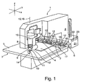
- Fig. 1 shows a machine tool 1 for cutting and / or forming plate-like workpieces in the form of a stamping / forming machine for processing sheets.
- the punching / forming machine 1 has a C-shaped machine frame 2 , in the throat area of which a workpiece support 3 designed as a workpiece support is arranged, which serves for supporting a workpiece to be machined in the form of a sheet 4 .
- the workpiece table 3 forms a horizontal support plane 5 for the sheet 4 to be processed , which is parallel to the x / y plane of the in Fig. 1 shown coordinate system runs.
- the clamping device 7 clamped sheet 4 in the support plane 5 of the workpiece table 3 is displaced.
- a punch-receiving 8 is arranged, in which a punch 9 is mounted. Furthermore, at the front end of the lower leg of the C-shaped machine frame 2, a female receptacle 10 is provided, in which a Punching die 11 is stored. The punch 9 and the punching die 11 form a tool 12 for cutting the sheet 4.
- a drive unit of the punching / forming machine 1 is formed by a punch drive 13 and a die drive 14 in the form of linear drives.
- the punch drive 13 By means of the punch drive 13, the punch receptacle 8 together with the stamped or fixed punch 9 mounted along a lifting axis 15 relative to the workpiece table 3 can be raised and lowered.
- the die holder 10 together with the stamped die 11 mounted or fixed therein can be raised and lowered by means of the die drive 14 along the lifting axis 15 relative to the workpiece table 3.
- the punch holder 8 and the die holder 10 are independently rotatable by means of a rotary drive, not shown in detail, about an identical with the lifting axis 15 tool axis of rotation 16 .
- a linear magazine 17 is provided with further tools 12.
- the tools 12 located in the linear magazine 17 are each held by a tool cassette 18 and can be fixed to the stamp holder 8 or the female holder 10 as required for machining the sheet 4, with tools 12 in particular also being used for forming the workpiece 2 can be kept in the linear magazine 17.
- the numerical control unit 19 comprises storage means 20 for storing tool data, and control means 21 for detecting both the raising, lowering and rotating movements of the punch holder 8 and the lifting, lowering and rotating movements of the die holder 10 based on the Figs stored data on the workpiece 4 and the tool 12 to measure and control.
- Fig. 2a shows a detailed view of the stored in the female receptacle 10 punching die 11 of Fig. 1 , on whose flat bearing surface 23 a deformed workpiece part 22 rests that of the in Fig. 1 shown workpiece 4 by punching processing along a formed in the support surface 23 opening 24 separated has been.
- punching die 11 has the problem that the separated, resting on the support surface 23 workpiece part 22 must be ejected by pushing, which can be done for example by means of a (not shown) scraper (eg in the form of a Eladurfeder) as a guide on the punch 9.
- a scraper eg in the form of a Eladurfeder
- the pushing can be dispensed with if the punching die 11 as in FIGS. 2 B , c shown has a truncated pyramidal geometry, wherein the top surface of the truncated pyramid forms the support surface 23 for the workpiece part 22 and the lateral surface of the truncated pyramid serves as Ausschleusschräge 25 .
- Fig. 2b respectively.
- Fig. 2c is shown, the upwardly or downwardly formed workpiece part 22 after the separating processing only partially on the support surface 23 and can be discharged along the Ausschleusschräge 25, which will be described below with reference to the FIGS. 3a -c is described.
- the diameter of the punching die 11 or the die holder 10 can be in the range of approximately 100 mm, for example.
- Fig. 3a shows the workpiece part 22 in a machining position B, in which this as in Fig. 2c shown rests on the support surface 23 of the punching die 11 and is separated from the remainder of the workpiece 4 by the punch 9 engages in the opening 24.
- Fig. 3a can also be seen, is the workpiece part 22 after the separating machining with its center of gravity S on the Ausschleusschräge 25.
- the cutting of the contour of the workpiece part 22 is planned in the control unit 19 so that the center of gravity S at the final separating cut so far away from the opening 24 that it no longer lies on the support surface 23.
- the free-cut workpiece part 22 tilts under the action of gravity about a tilting edge 26 formed on the edge of the support surface 23 from the processing position B to a discharge position AB, in which the workpiece part 22 rests on the discharge slope 25 of the punching die 11, cf. Fig. 3b ,
- the Ausschleusschräge 25 is inclined relative to the support surface 23 of the punching die 11 and the workpiece plane 5 at a tilt angle a, which is approximately 45 ° in the present case.
- the workpiece part 22 subsequently slides under the action of gravity on the discharge slope 25 of the punching die 11 into a discharge position AS (see FIG. Fig. 3c ), in which the workpiece part 22 rests on a subsequent to the Ausschleusschräge 25 rigid chute 27 on which the workpiece part 22 further slides to be discharged from the machine tool 1.
- the support surface 23 of the punching die 11 is in the workpiece plane 5, to support the workpiece part 22 during the punching process.
- the die holder 10 is positioned by the punching processing below the workpiece plane 5, for which purpose the die holder 10 is typically lowered by approximately 30 mm with respect to the workpiece plane 5.
- punching die 11 is also possible to edit at a correspondingly provided Ausschleusposition AP, for example by roll forming formed workpiece parts 4 above or below the workpiece plane 5.
- a slide movable along the lifting axis 15 can be provided or another transport means, eg a conveyor belt, can be provided for discharging the workpiece part 22 at the discharge position AS.
- the workpiece part 22 can be quickly removed from the workpiece plane 5, wherein, if necessary, a shift of the workpiece 4 along the workpiece plane 5 for subsequent processing can already be done while the workpiece part 22 slides along the discharge slope 25.
- the lateral surface 25 of the punching die 11 also further lateral surfaces can serve as Ausschleusschräge, for example, an opposite lateral surface 25 a , to which a in FIGS. 3a-c dashed lines, another slide 27a can connect.
- the punching die 11 is not mandatory pyramidal and can also be carried out in other ways, for example, truncated cone or asymmetric.
- FIGS. 4a , b show such an asymmetric punching die 11 ', in which both the opening 24 for engagement for the punch 9 and between the edge 26 and the Ausschleusschräge 11' formed in the vertical direction (Z-direction) extending Abstanz materials 28 are arranged eccentrically.
- the likewise asymmetrically formed punch 9 can by a 180 ° rotation about the axis of rotation 16 with a cutting edge 9a either over the opening 24 (see. Fig. 4a ) or on the Abstanzization 28 or at the edge 26 are positioned (see. Fig. 4b ).
- the workpiece 4 is hereby optionally punched processed by the punch 9 and the cutting edge 9a is brought into engagement with the opening 24 or guided along the Abstanz requirements 28 along.
- the opening 24 can also be widened toward the center of the punching die 11 'in order to allow ejection of workpiece parts through the opening 24.
- the punch 9 and the punching die 11 ' may also be formed as a forming tool, by means of which in addition to the punching at the in the in Fig. 4a shown position a deformation can be made on the workpiece.
- the edge 26 for punching the workpiece may alternatively be arranged centrally on the punching die 11 '.
- the central cutting edge 9a of the punch 9 is lowered onto the punching die 11 'in order to punch the workpiece part at the cutting edge 26 or along the cutting surface 28.
- no opening is made in the support surface 23 of the punching die 11 ', since the rotation of the punch 9 or of the punching die 11' in this case does not open any additional processing options on the workpiece.
- Fig. 5b shows a further punching die 11 ", in which the Ausschleusschräge 25 is mounted below the opening 24 in the support surface 23.
- the punch 9 in this case has a cutting edge 9a, which can be brought into engagement with the opening 24 to one above the opening 24th In this case, the separated workpiece part is lowered in a combined linear and rotary movement onto the bearing surface 25. It is understood that in the right subregion of the bearing surface 23 there is an additional opening for the workpiece punching editing a workpiece can be introduced. It is further understood that for discharging large workpiece parts other than in Fig. 5b shown the Ausschleusschräge can extend over almost the entire cross-section of the punching die 11 ", in which case the support surface is formed by a narrow, for example, annular edge.
- the angle ⁇ between the support surface 23 and the Ausschleusschräge 25 can be steeper or shallower than in this case FIGS. 6a-c shown (about 45 °) and is typically between 20 ° and 80 °.
- the discharge is made possible with high process reliability, since the discharge position AS is located below the workpiece support and hooking of the workpiece part can be effectively prevented at the remainder workpiece in the discharge process described above.
Landscapes
- Engineering & Computer Science (AREA)
- Mechanical Engineering (AREA)
- Punching Or Piercing (AREA)
- Perforating, Stamping-Out Or Severing By Means Other Than Cutting (AREA)
- Electrical Discharge Machining, Electrochemical Machining, And Combined Machining (AREA)
- Turning (AREA)
Claims (12)
- Machine-outil (1) dédiée à la découpe et/ou à la mise en forme de pièces à usiner (4) du type plaques, de préférence des tôles, comprenant :une matrice de poinçonnage (11, 11', 11 ") conçue pour séparer une partie (22) de pièce à usiner notamment mise en forme, située dans une zone d'usinage (B), d'une pièce à usiner (4) reposant sur une surface de support (23) de ladite matrice de poinçonnage (11, 11', 11"),ladite matrice de poinçonnage (11', 11") étant munie d'une rampe d'évacuation (25) sur laquelle est formée une zone d'enlèvement (AB) à laquelle ladite partie (22) de pièce à usiner peut être présentée à partir de ladite zone d'usinage (B), de préférence par gravité, en effectuant un mouvement rotatoire, basculant et/ou linéaire, etladite machine-outil (1) comportant une zone d'évacuation (AS) qui est prévue au-dessous d'un plateau (3) repose-pièces, au voisinage de la matrice de poinçonnage (11', 11"), et à laquelle ladite partie (22) de pièce à usiner peut être présentée de préférence par gravité, en effectuant un mouvement de glissement le long de ladite rampe d'évacuation (25),caractérisée par le fait
que la rampe d'évacuation (25) de la matrice de poinçonnage (11 ") est disposée au-dessous d'un orifice (24) pratiqué dans la surface de support (23), pour permettre l'engagement d'un poinçon (9) ; ou
qu'un bord extérieur de la surface de support (23) de la matrice de poinçonnage (11') offre une arête (26) fusionnant dans ladite rampe d'évacuation (25), une surface de découpage (28) étant formée entre ladite arête (26) et ladite rampe d'évacuation (25) de ladite matrice de poinçonnage (11'). - Machine-outil selon la revendication 1, dans laquelle la surface de découpage (28) occupe une position excentrée ; et dans laquelle la surface de support (23) présente un orifice (24) qui occupe une position excentrée, pour permettre l'engagement d'un poinçon (9).
- Machine-outil selon l'une des revendications précédentes, dans laquelle un glissoir (27), situé dans la zone d'évacuation (AS), se trouve dans la continuité directe de la rampe d'évacuation (25) de la matrice de poinçonnage (11).
- Machine-outil selon l'une des revendications précédentes, dans laquelle la rampe d'évacuation est ménagée sur une surface périphérique (25) d'une matrice de poinçonnage (11) revêtant la forme d'une pyramide, ou d'un tronc de cône.
- Machine-outil selon l'une des revendications précédentes, dans laquelle le bord inférieur de la rampe d'évacuation (25) est limitrophe d'un logement (10) dans lequel la matrice de poinçonnage (11) est montée.
- Machine-outil selon l'une des revendications précédentes, dans laquelle la surface de support (23) décrit, avec la rampe d'évacuation (25), un angle (α) compris entre 20° et 80°, de préférence entre 25° et 45°.
- Machine-outil selon l'une des revendications précédentes, comprenant en outre une unité de commande (19) affectée au positionnement de la partie (22) de pièce à usiner, dans la zone d'usinage (B), de façon telle que le centre de gravité (S) de ladite partie (22) de pièce à usiner soit situé au-dessus de la rampe d'évacuation (25).
- Machine-outil selon l'une des revendications précédentes, comprenant en outre
un logement (10), dans lequel la matrice de poinçonnage (11) est montée,
un logement (8), dans lequel un poinçon (9) est monté,
ainsi qu'une unité d'entraînement (13, 14) au moyen de laquelle ledit logement (8) de poinçon et ledit logement (10) de matrice peuvent être mus en direction l'un de l'autre, le long d'un axe de levage (15), pour effectuer une opération de séparation sur la partie (22) de pièce à usiner, dans la zone d'usinage (B). - Procédé d'évacuation, à partir d'une matrice de poinçonnage (11, 11'), d'une partie (22) de pièce à usiner notamment mise en forme sur une machine-outil (1) dédiée à la découpe et/ou à la mise en forme de pièces à usiner (4) du type plaques, de préférence des tôles, consistant à :séparer ladite partie (22) de pièce à usiner, située dans une zone d'usinage (B), de la pièce à usiner (4) reposant sur une surface de support (23) de ladite matrice de poinçonnage (11,11'),ladite partie (22) de pièce à usiner étant présentée à partir de ladite zone d'usinage (B), de préférence par gravité et en effectuant un mouvement rotatoire, basculant et/ou linéaire, à une zone d'enlèvement (AB) située sur une rampe d'évacuation (25) ménagée sur la matrice de poinçonnage (11), et
ladite partie (22) de pièce à usiner étant présentée le long de ladite rampe d'évacuation (25) en effectuant un mouvement de glissement, de préférence par gravité, à une zone d'évacuation (AS) qui est prévue au-dessous du plateau (3) repose-pièces et au voisinage de ladite matrice de poinçonnage (11),
caractérisé par le fait
que l'usinage à effet de séparation est exécuté par pénétration d'un poinçon (9) dans un orifice (24) qui est pratiqué dans la surface de support (23), et au-dessous duquel la rampe d'évacuation (25) de la matrice de poinçonnage (11 ") est disposée ; ou
que ledit usinage à effet de séparation est exécuté par guidage d'un poinçon (9) le long d'une surface de découpage (28), formée entre ladite rampe d'évacuation (25) et une arête (26) située sur un bord extérieur de ladite surface de support (23) de la matrice de poinçonnage (11'). - Procédé selon la revendication 9, dans lequel la matrice de poinçonnage (11) est montée dans un logement (10) auquel un mouvement est imprimé le long d'un axe de levage (15), avant ou après l'usinage à effet de séparation, jusqu'à ce que la rampe d'évacuation (25) de ladite matrice de poinçonnage (11) fusionne directement dans un glissoir (27) de la machine-outil (1), prévu dans la zone d'évacuation (AS).
- Procédé selon la revendication 9 ou 10, dans lequel la partie (22) de pièce à usiner est positionnée, dans la zone d'usinage (B), de façon telle que le centre de gravité (S) de ladite partie (22) de pièce à usiner soit situé au-dessus de la rampe d'évacuation (25).
- Procédé selon l'une des revendications 9 à 11, dans lequel la pièce à usiner (4) est sélectivement usinée, par découpe, au niveau d'un orifice (24) pratiqué dans la surface de support (23) de la matrice de poinçonnage (11'), ou au niveau de la surface de découpage (28).
Priority Applications (5)
| Application Number | Priority Date | Filing Date | Title |
|---|---|---|---|
| EP20080018301 EP2177289B1 (fr) | 2008-10-20 | 2008-10-20 | Machines-outils et procédé destinés à l'évacuation d'une partie d'une pièce à usiner |
| PL08018301T PL2177289T3 (pl) | 2008-10-20 | 2008-10-20 | Obrabiarki i sposób usuwania części detalu |
| AT08018301T ATE515336T1 (de) | 2008-10-20 | 2008-10-20 | Werkzeugmaschinen und verfahren zum ausschleusen eines werkstückteils |
| US12/581,992 US8499668B2 (en) | 2008-10-20 | 2009-10-20 | Discharging workpiece parts |
| JP2009241296A JP5542407B2 (ja) | 2008-10-20 | 2009-10-20 | 工作機械およびワーク部分を取り出すための方法 |
Applications Claiming Priority (1)
| Application Number | Priority Date | Filing Date | Title |
|---|---|---|---|
| EP20080018301 EP2177289B1 (fr) | 2008-10-20 | 2008-10-20 | Machines-outils et procédé destinés à l'évacuation d'une partie d'une pièce à usiner |
Publications (2)
| Publication Number | Publication Date |
|---|---|
| EP2177289A1 EP2177289A1 (fr) | 2010-04-21 |
| EP2177289B1 true EP2177289B1 (fr) | 2011-07-06 |
Family
ID=41213304
Family Applications (1)
| Application Number | Title | Priority Date | Filing Date |
|---|---|---|---|
| EP20080018301 Active EP2177289B1 (fr) | 2008-10-20 | 2008-10-20 | Machines-outils et procédé destinés à l'évacuation d'une partie d'une pièce à usiner |
Country Status (5)
| Country | Link |
|---|---|
| US (1) | US8499668B2 (fr) |
| EP (1) | EP2177289B1 (fr) |
| JP (1) | JP5542407B2 (fr) |
| AT (1) | ATE515336T1 (fr) |
| PL (1) | PL2177289T3 (fr) |
Cited By (4)
| Publication number | Priority date | Publication date | Assignee | Title |
|---|---|---|---|---|
| WO2018055182A1 (fr) | 2016-09-26 | 2018-03-29 | Trumpf Werkzeugmaschinen Gmbh + Co. Kg | Outil et machine-outil, ainsi que procédé de découpe et/ou de formage de pièces en forme de plaque |
| WO2018055184A1 (fr) | 2016-09-26 | 2018-03-29 | Trumpf Werkzeugmaschinen Gmbh + Co. Kg | Outil et machine-outil ainsi que procédé d'usinage de pièces en forme de plaque, en particulier de tôles |
| DE102016119435A1 (de) | 2016-10-12 | 2018-04-12 | Trumpf Werkzeugmaschinen Gmbh + Co. Kg | Werkzeug und Werkzeugmaschine sowie Verfahren zum Bearbeiten von plattenförmigen Werkstücken |
| DE102016119434A1 (de) | 2016-10-12 | 2018-04-12 | Trumpf Werkzeugmaschinen Gmbh + Co. Kg | Werkzeug und Werkzeugmaschine sowie Verfahren zum Schneiden und/oder Umformen von plattenförmigen Werkstücken |
Families Citing this family (15)
| Publication number | Priority date | Publication date | Assignee | Title |
|---|---|---|---|---|
| DE102010061321A1 (de) * | 2010-12-17 | 2012-06-21 | Gustav Klauke Gmbh | Verfahren zum Fräsen einer Ausnehmung in einem Werkstück und Werkstück mit einer Ausnehmung |
| CN102189171A (zh) * | 2011-04-18 | 2011-09-21 | 无锡新大力电机有限公司 | 一种冲片冲槽模具 |
| US9808842B2 (en) | 2011-08-18 | 2017-11-07 | Justrite Manufacturing Company, L.L.C. | Gas evacuation system with counter |
| FR2990886B1 (fr) * | 2012-05-24 | 2014-05-09 | Peugeot Citroen Automobiles Sa | Procede pour la fabrication d'une piece en tole. |
| US20140033886A1 (en) * | 2012-08-01 | 2014-02-06 | Xerox Corporation | Document Production System and Method With Automated Die Exchange |
| US9845232B2 (en) | 2014-02-17 | 2017-12-19 | Justrite Manufacturing Company, Llc | Puncturing device for aerosol containers |
| US9993764B2 (en) | 2014-04-01 | 2018-06-12 | Justrite Manufacturing Company, Llc | Filter for a propellant gas evacuation system |
| JP6356546B2 (ja) * | 2014-09-05 | 2018-07-11 | 日伸工業株式会社 | 異形ブランク打ち抜き装置 |
| KR101787662B1 (ko) * | 2014-10-08 | 2017-10-19 | 한온시스템 주식회사 | 표면조도 개선을 위한 도트 펀칭 가공장치와 이를 이용한 패턴 가공 방법 및 그 패턴이 구비된 압축기용 밸브플레이트 |
| US9827528B2 (en) | 2015-04-01 | 2017-11-28 | Justrite Manufacturing Company, Llc | Filter for a propellant gas evacuation system |
| TWI572422B (zh) * | 2015-06-04 | 2017-03-01 | Silicone sheet continuous die device | |
| PL3106241T3 (pl) | 2015-06-19 | 2018-01-31 | Trumpf Werkzeugmaschinen Gmbh Co Kg | Obrabiarka oraz sposób odprowadzania części przedmiotu obrabianego |
| USD797825S1 (en) * | 2015-10-05 | 2017-09-19 | Wolter Corp. | Metal stamp jig |
| USD798918S1 (en) * | 2015-11-25 | 2017-10-03 | Justrite Manufacturing Company, L.L.C. | Shield for puncturing device |
| DE102017123723B4 (de) * | 2017-10-12 | 2023-03-16 | Tkr Spezialwerkzeuge Gmbh | Hydraulisches Stanzgerät |
Family Cites Families (20)
| Publication number | Priority date | Publication date | Assignee | Title |
|---|---|---|---|---|
| US2146780A (en) * | 1936-03-17 | 1939-02-14 | George F Wales | Apparatus for notching sheet material |
| US2363630A (en) * | 1942-03-04 | 1944-11-28 | George F Wales | Notching apparatus |
| US2744575A (en) * | 1954-01-04 | 1956-05-08 | Toolset Inc | Notching unit |
| CH531377A (de) * | 1968-04-11 | 1972-12-15 | Kondo Kazuyoshi | Schneidverfahren und Schnittwerkzeug zur Durchführung desselben |
| DE1930398C3 (de) | 1969-06-14 | 1974-06-06 | Maschinenfabrik Lorenz Ag, 7505 Ettlingen | Feinschnittpresse |
| US3739669A (en) | 1970-05-29 | 1973-06-19 | Suzuki Motor Co | Shearing press of opposing die type |
| JPS52169893U (fr) * | 1976-06-16 | 1977-12-23 | ||
| JPS55165235A (en) * | 1979-06-12 | 1980-12-23 | Toyota Motor Corp | Press blanking die |
| JPS57194743A (en) | 1981-05-20 | 1982-11-30 | Nippon Suisan Kaisha Ltd | Method for aseptic cooling of hamburger steak, etc. |
| JPS57194743U (fr) * | 1981-06-04 | 1982-12-10 | ||
| NL8902274A (nl) | 1989-09-12 | 1991-04-02 | Brouwer & Co Machine | Ponsmachine. |
| JPH0443416A (ja) | 1990-06-08 | 1992-02-13 | Brother Ind Ltd | 電子機器 |
| JP2527538Y2 (ja) * | 1990-08-10 | 1997-03-05 | 株式会社アマダメトレックス | パンチプレスにおける金型装置 |
| FI106187B (fi) | 1991-12-16 | 2000-12-15 | Amada Co Ltd | Revolverilävistyspuristin |
| FI100648B (fi) | 1995-12-14 | 1998-01-30 | Balaxman Oy | Levytyökeskus |
| JP3974263B2 (ja) * | 1998-04-07 | 2007-09-12 | 力夫 西田 | パンチャーヘッド及びパンチャー |
| US6526800B1 (en) | 1998-04-08 | 2003-03-04 | Lillbacka Jetair Oy | Sheet fabrication center and methods therefor of optimally fabricating worksheets |
| JP3700569B2 (ja) * | 2000-10-04 | 2005-09-28 | 村田機械株式会社 | タレットパンチプレス |
| JP4279532B2 (ja) | 2002-10-01 | 2009-06-17 | 株式会社アマダ | 成形製品の加工方法に使用する金型装置及び下金型 |
| DE102006049044B4 (de) * | 2006-10-18 | 2018-01-11 | Trumpf Werkzeugmaschinen Gmbh + Co. Kg | Werkzeug zum Schneiden von plattenartigen Werkstücken |
-
2008
- 2008-10-20 EP EP20080018301 patent/EP2177289B1/fr active Active
- 2008-10-20 PL PL08018301T patent/PL2177289T3/pl unknown
- 2008-10-20 AT AT08018301T patent/ATE515336T1/de active
-
2009
- 2009-10-20 US US12/581,992 patent/US8499668B2/en active Active
- 2009-10-20 JP JP2009241296A patent/JP5542407B2/ja not_active Expired - Fee Related
Cited By (4)
| Publication number | Priority date | Publication date | Assignee | Title |
|---|---|---|---|---|
| WO2018055182A1 (fr) | 2016-09-26 | 2018-03-29 | Trumpf Werkzeugmaschinen Gmbh + Co. Kg | Outil et machine-outil, ainsi que procédé de découpe et/ou de formage de pièces en forme de plaque |
| WO2018055184A1 (fr) | 2016-09-26 | 2018-03-29 | Trumpf Werkzeugmaschinen Gmbh + Co. Kg | Outil et machine-outil ainsi que procédé d'usinage de pièces en forme de plaque, en particulier de tôles |
| DE102016119435A1 (de) | 2016-10-12 | 2018-04-12 | Trumpf Werkzeugmaschinen Gmbh + Co. Kg | Werkzeug und Werkzeugmaschine sowie Verfahren zum Bearbeiten von plattenförmigen Werkstücken |
| DE102016119434A1 (de) | 2016-10-12 | 2018-04-12 | Trumpf Werkzeugmaschinen Gmbh + Co. Kg | Werkzeug und Werkzeugmaschine sowie Verfahren zum Schneiden und/oder Umformen von plattenförmigen Werkstücken |
Also Published As
| Publication number | Publication date |
|---|---|
| JP5542407B2 (ja) | 2014-07-09 |
| EP2177289A1 (fr) | 2010-04-21 |
| ATE515336T1 (de) | 2011-07-15 |
| US8499668B2 (en) | 2013-08-06 |
| JP2010094739A (ja) | 2010-04-30 |
| US20100095815A1 (en) | 2010-04-22 |
| PL2177289T3 (pl) | 2011-12-30 |
Similar Documents
| Publication | Publication Date | Title |
|---|---|---|
| EP2177289B1 (fr) | Machines-outils et procédé destinés à l'évacuation d'une partie d'une pièce à usiner | |
| EP3463734B1 (fr) | Machine pour séparer par usinage une pièce sous forme de plaque et procédé pour éjecter une partie de pièce dégagée par découpe | |
| EP3106241B1 (fr) | Machine-outil et procédé destinés a l'évacuation de parties d'une pièce à usiner | |
| EP3083127B1 (fr) | Machine pour séparer par usinage des pièces en forme de plaques et son utilisation | |
| EP3083123B1 (fr) | Machine pour diviser des pièces en forme de plaques et son utilisation | |
| EP2656937B1 (fr) | Procédé pour ménager une déformation dans une plaque en tôle | |
| EP2184116B1 (fr) | Procédé destiné à évacuer des éléments en tôle de machines de poinçonnage | |
| EP3515623B1 (fr) | Outil et machine-outil ainsi que procédé d'usinage de pièces en forme de plaque, en particulier de tôles | |
| EP2177291B1 (fr) | Procédé de découpe et/ou formage de pièces | |
| EP2092994B1 (fr) | Machine-outil destinée à la coupe et/ou au formage de pièces à usiner en plaques | |
| EP2335841B1 (fr) | Procédé de fabrication de pièces pliées et outil correspondant | |
| EP3684545B1 (fr) | Procédé destiné à définir des positions de retrait et/ou des positions de retenue, dispositif destiné à retirer une partie de pièce et machine d'usinage | |
| WO2022073748A1 (fr) | Procédé et machine pour couper et retirer des parties de pièces dans un matériau en forme de plaque | |
| EP2260975B1 (fr) | Rectifieuse plane et procédé de traitement de pièce usinée par rectification plane | |
| EP2692455B1 (fr) | Machine-outil pour l'usinage de pièces en forme de plaque, notamment de tôles | |
| EP0074041B1 (fr) | Dispositif de découpe pour des pièces plates | |
| DE2637085C3 (de) | Vorrichtung zum Ausstoßen des Stanzabfalles oder Stanzteils mittels Druckluft | |
| EP3515622B1 (fr) | Outil et machine-outil, ainsi que procédé de découpe et/ou de formage de pièces en forme de plaque | |
| DE202018002305U1 (de) | Vorrichtung zum Heraustrennen eines Werkstücks | |
| DE102018003622A1 (de) | Vorrichtung und Verfahren zum Heraustrennen eines Werkstücks | |
| DE102016120151A1 (de) | Verfahren und Werkzeugmaschine zum Bearbeiten von plattenförmigen Werkstücken, insbesondere von Blechen | |
| EP3288696A1 (fr) | Outil pour poinçonneuse et procédé d'usinage d'une face frontale d'une pièce en forme de plaque | |
| DE102020133084B3 (de) | Formwerkzeug und Verfahren | |
| WO2018055178A1 (fr) | Procédé et machine-outil servant à l'usinage de pièces en forme de plaque, en particulier de tôles | |
| WO2004112982A1 (fr) | Machine et procede d'estampage de pieces |
Legal Events
| Date | Code | Title | Description |
|---|---|---|---|
| PUAI | Public reference made under article 153(3) epc to a published international application that has entered the european phase |
Free format text: ORIGINAL CODE: 0009012 |
|
| AK | Designated contracting states |
Kind code of ref document: A1 Designated state(s): AT BE BG CH CY CZ DE DK EE ES FI FR GB GR HR HU IE IS IT LI LT LU LV MC MT NL NO PL PT RO SE SI SK TR |
|
| AX | Request for extension of the european patent |
Extension state: AL BA MK RS |
|
| 17P | Request for examination filed |
Effective date: 20100707 |
|
| 17Q | First examination report despatched |
Effective date: 20100804 |
|
| AKX | Designation fees paid |
Designated state(s): AT BE BG CH CY CZ DE DK EE ES FI FR GB GR HR HU IE IS IT LI LT LU LV MC MT NL NO PL PT RO SE SI SK TR |
|
| GRAP | Despatch of communication of intention to grant a patent |
Free format text: ORIGINAL CODE: EPIDOSNIGR1 |
|
| GRAS | Grant fee paid |
Free format text: ORIGINAL CODE: EPIDOSNIGR3 |
|
| GRAA | (expected) grant |
Free format text: ORIGINAL CODE: 0009210 |
|
| AK | Designated contracting states |
Kind code of ref document: B1 Designated state(s): AT BE BG CH CY CZ DE DK EE ES FI FR GB GR HR HU IE IS IT LI LT LU LV MC MT NL NO PL PT RO SE SI SK TR |
|
| REG | Reference to a national code |
Ref country code: GB Ref legal event code: FG4D Free format text: NOT ENGLISH |
|
| REG | Reference to a national code |
Ref country code: CH Ref legal event code: EP |
|
| REG | Reference to a national code |
Ref country code: IE Ref legal event code: FG4D Free format text: LANGUAGE OF EP DOCUMENT: GERMAN |
|
| REG | Reference to a national code |
Ref country code: DE Ref legal event code: R096 Ref document number: 502008004092 Country of ref document: DE Effective date: 20110825 |
|
| REG | Reference to a national code |
Ref country code: NL Ref legal event code: VDEP Effective date: 20110706 |
|
| PG25 | Lapsed in a contracting state [announced via postgrant information from national office to epo] |
Ref country code: SI Free format text: LAPSE BECAUSE OF FAILURE TO SUBMIT A TRANSLATION OF THE DESCRIPTION OR TO PAY THE FEE WITHIN THE PRESCRIBED TIME-LIMIT Effective date: 20110706 |
|
| REG | Reference to a national code |
Ref country code: PL Ref legal event code: T3 |
|
| PG25 | Lapsed in a contracting state [announced via postgrant information from national office to epo] |
Ref country code: FI Free format text: LAPSE BECAUSE OF FAILURE TO SUBMIT A TRANSLATION OF THE DESCRIPTION OR TO PAY THE FEE WITHIN THE PRESCRIBED TIME-LIMIT Effective date: 20110706 Ref country code: NO Free format text: LAPSE BECAUSE OF FAILURE TO SUBMIT A TRANSLATION OF THE DESCRIPTION OR TO PAY THE FEE WITHIN THE PRESCRIBED TIME-LIMIT Effective date: 20111006 Ref country code: NL Free format text: LAPSE BECAUSE OF FAILURE TO SUBMIT A TRANSLATION OF THE DESCRIPTION OR TO PAY THE FEE WITHIN THE PRESCRIBED TIME-LIMIT Effective date: 20110706 Ref country code: PT Free format text: LAPSE BECAUSE OF FAILURE TO SUBMIT A TRANSLATION OF THE DESCRIPTION OR TO PAY THE FEE WITHIN THE PRESCRIBED TIME-LIMIT Effective date: 20111107 Ref country code: SE Free format text: LAPSE BECAUSE OF FAILURE TO SUBMIT A TRANSLATION OF THE DESCRIPTION OR TO PAY THE FEE WITHIN THE PRESCRIBED TIME-LIMIT Effective date: 20110706 Ref country code: HR Free format text: LAPSE BECAUSE OF FAILURE TO SUBMIT A TRANSLATION OF THE DESCRIPTION OR TO PAY THE FEE WITHIN THE PRESCRIBED TIME-LIMIT Effective date: 20110706 Ref country code: IS Free format text: LAPSE BECAUSE OF FAILURE TO SUBMIT A TRANSLATION OF THE DESCRIPTION OR TO PAY THE FEE WITHIN THE PRESCRIBED TIME-LIMIT Effective date: 20111106 Ref country code: LT Free format text: LAPSE BECAUSE OF FAILURE TO SUBMIT A TRANSLATION OF THE DESCRIPTION OR TO PAY THE FEE WITHIN THE PRESCRIBED TIME-LIMIT Effective date: 20110706 |
|
| REG | Reference to a national code |
Ref country code: IE Ref legal event code: FD4D |
|
| PG25 | Lapsed in a contracting state [announced via postgrant information from national office to epo] |
Ref country code: LV Free format text: LAPSE BECAUSE OF FAILURE TO SUBMIT A TRANSLATION OF THE DESCRIPTION OR TO PAY THE FEE WITHIN THE PRESCRIBED TIME-LIMIT Effective date: 20110706 Ref country code: CY Free format text: LAPSE BECAUSE OF FAILURE TO SUBMIT A TRANSLATION OF THE DESCRIPTION OR TO PAY THE FEE WITHIN THE PRESCRIBED TIME-LIMIT Effective date: 20110706 Ref country code: GR Free format text: LAPSE BECAUSE OF FAILURE TO SUBMIT A TRANSLATION OF THE DESCRIPTION OR TO PAY THE FEE WITHIN THE PRESCRIBED TIME-LIMIT Effective date: 20111007 |
|
| BERE | Be: lapsed |
Owner name: TRUMPF WERKZEUGMASCHINEN G.M.B.H. + CO. KG Effective date: 20111031 |
|
| PG25 | Lapsed in a contracting state [announced via postgrant information from national office to epo] |
Ref country code: SK Free format text: LAPSE BECAUSE OF FAILURE TO SUBMIT A TRANSLATION OF THE DESCRIPTION OR TO PAY THE FEE WITHIN THE PRESCRIBED TIME-LIMIT Effective date: 20110706 Ref country code: IE Free format text: LAPSE BECAUSE OF FAILURE TO SUBMIT A TRANSLATION OF THE DESCRIPTION OR TO PAY THE FEE WITHIN THE PRESCRIBED TIME-LIMIT Effective date: 20110706 |
|
| PLBE | No opposition filed within time limit |
Free format text: ORIGINAL CODE: 0009261 |
|
| STAA | Information on the status of an ep patent application or granted ep patent |
Free format text: STATUS: NO OPPOSITION FILED WITHIN TIME LIMIT |
|
| PG25 | Lapsed in a contracting state [announced via postgrant information from national office to epo] |
Ref country code: EE Free format text: LAPSE BECAUSE OF FAILURE TO SUBMIT A TRANSLATION OF THE DESCRIPTION OR TO PAY THE FEE WITHIN THE PRESCRIBED TIME-LIMIT Effective date: 20110706 Ref country code: RO Free format text: LAPSE BECAUSE OF FAILURE TO SUBMIT A TRANSLATION OF THE DESCRIPTION OR TO PAY THE FEE WITHIN THE PRESCRIBED TIME-LIMIT Effective date: 20110706 Ref country code: MC Free format text: LAPSE BECAUSE OF NON-PAYMENT OF DUE FEES Effective date: 20111031 |
|
| 26N | No opposition filed |
Effective date: 20120411 |
|
| PG25 | Lapsed in a contracting state [announced via postgrant information from national office to epo] |
Ref country code: DK Free format text: LAPSE BECAUSE OF FAILURE TO SUBMIT A TRANSLATION OF THE DESCRIPTION OR TO PAY THE FEE WITHIN THE PRESCRIBED TIME-LIMIT Effective date: 20110706 |
|
| PG25 | Lapsed in a contracting state [announced via postgrant information from national office to epo] |
Ref country code: BE Free format text: LAPSE BECAUSE OF NON-PAYMENT OF DUE FEES Effective date: 20111031 |
|
| REG | Reference to a national code |
Ref country code: DE Ref legal event code: R097 Ref document number: 502008004092 Country of ref document: DE Effective date: 20120411 |
|
| PG25 | Lapsed in a contracting state [announced via postgrant information from national office to epo] |
Ref country code: MT Free format text: LAPSE BECAUSE OF FAILURE TO SUBMIT A TRANSLATION OF THE DESCRIPTION OR TO PAY THE FEE WITHIN THE PRESCRIBED TIME-LIMIT Effective date: 20110706 |
|
| PG25 | Lapsed in a contracting state [announced via postgrant information from national office to epo] |
Ref country code: ES Free format text: LAPSE BECAUSE OF FAILURE TO SUBMIT A TRANSLATION OF THE DESCRIPTION OR TO PAY THE FEE WITHIN THE PRESCRIBED TIME-LIMIT Effective date: 20111017 |
|
| PG25 | Lapsed in a contracting state [announced via postgrant information from national office to epo] |
Ref country code: LU Free format text: LAPSE BECAUSE OF NON-PAYMENT OF DUE FEES Effective date: 20111020 |
|
| PG25 | Lapsed in a contracting state [announced via postgrant information from national office to epo] |
Ref country code: BG Free format text: LAPSE BECAUSE OF FAILURE TO SUBMIT A TRANSLATION OF THE DESCRIPTION OR TO PAY THE FEE WITHIN THE PRESCRIBED TIME-LIMIT Effective date: 20111006 |
|
| PG25 | Lapsed in a contracting state [announced via postgrant information from national office to epo] |
Ref country code: TR Free format text: LAPSE BECAUSE OF FAILURE TO SUBMIT A TRANSLATION OF THE DESCRIPTION OR TO PAY THE FEE WITHIN THE PRESCRIBED TIME-LIMIT Effective date: 20110706 |
|
| PG25 | Lapsed in a contracting state [announced via postgrant information from national office to epo] |
Ref country code: HU Free format text: LAPSE BECAUSE OF FAILURE TO SUBMIT A TRANSLATION OF THE DESCRIPTION OR TO PAY THE FEE WITHIN THE PRESCRIBED TIME-LIMIT Effective date: 20110706 |
|
| REG | Reference to a national code |
Ref country code: FR Ref legal event code: PLFP Year of fee payment: 8 |
|
| REG | Reference to a national code |
Ref country code: FR Ref legal event code: PLFP Year of fee payment: 9 |
|
| REG | Reference to a national code |
Ref country code: FR Ref legal event code: PLFP Year of fee payment: 10 |
|
| REG | Reference to a national code |
Ref country code: FR Ref legal event code: PLFP Year of fee payment: 11 |
|
| PGFP | Annual fee paid to national office [announced via postgrant information from national office to epo] |
Ref country code: PL Payment date: 20210920 Year of fee payment: 14 |
|
| PGFP | Annual fee paid to national office [announced via postgrant information from national office to epo] |
Ref country code: AT Payment date: 20211021 Year of fee payment: 14 Ref country code: CZ Payment date: 20211020 Year of fee payment: 14 Ref country code: GB Payment date: 20211022 Year of fee payment: 14 |
|
| PGFP | Annual fee paid to national office [announced via postgrant information from national office to epo] |
Ref country code: IT Payment date: 20211028 Year of fee payment: 14 Ref country code: FR Payment date: 20211021 Year of fee payment: 14 Ref country code: CH Payment date: 20211020 Year of fee payment: 14 |
|
| REG | Reference to a national code |
Ref country code: CH Ref legal event code: PL |
|
| REG | Reference to a national code |
Ref country code: AT Ref legal event code: MM01 Ref document number: 515336 Country of ref document: AT Kind code of ref document: T Effective date: 20221020 |
|
| GBPC | Gb: european patent ceased through non-payment of renewal fee |
Effective date: 20221020 |
|
| PG25 | Lapsed in a contracting state [announced via postgrant information from national office to epo] |
Ref country code: LI Free format text: LAPSE BECAUSE OF NON-PAYMENT OF DUE FEES Effective date: 20221031 Ref country code: FR Free format text: LAPSE BECAUSE OF NON-PAYMENT OF DUE FEES Effective date: 20221031 Ref country code: CZ Free format text: LAPSE BECAUSE OF NON-PAYMENT OF DUE FEES Effective date: 20221020 Ref country code: CH Free format text: LAPSE BECAUSE OF NON-PAYMENT OF DUE FEES Effective date: 20221031 Ref country code: AT Free format text: LAPSE BECAUSE OF NON-PAYMENT OF DUE FEES Effective date: 20221020 |
|
| PG25 | Lapsed in a contracting state [announced via postgrant information from national office to epo] |
Ref country code: IT Free format text: LAPSE BECAUSE OF NON-PAYMENT OF DUE FEES Effective date: 20221020 Ref country code: GB Free format text: LAPSE BECAUSE OF NON-PAYMENT OF DUE FEES Effective date: 20221020 |
|
| PGFP | Annual fee paid to national office [announced via postgrant information from national office to epo] |
Ref country code: DE Payment date: 20231020 Year of fee payment: 16 |