EP3515622B1 - Outil et machine-outil, ainsi que procédé de découpe et/ou de formage de pièces en forme de plaque - Google Patents
Outil et machine-outil, ainsi que procédé de découpe et/ou de formage de pièces en forme de plaque Download PDFInfo
- Publication number
- EP3515622B1 EP3515622B1 EP17783413.2A EP17783413A EP3515622B1 EP 3515622 B1 EP3515622 B1 EP 3515622B1 EP 17783413 A EP17783413 A EP 17783413A EP 3515622 B1 EP3515622 B1 EP 3515622B1
- Authority
- EP
- European Patent Office
- Prior art keywords
- tool
- cutting edge
- cutting
- lower tool
- workpiece
- Prior art date
- Legal status (The legal status is an assumption and is not a legal conclusion. Google has not performed a legal analysis and makes no representation as to the accuracy of the status listed.)
- Active
Links
- 238000005520 cutting process Methods 0.000 title claims description 271
- 238000000034 method Methods 0.000 title claims description 16
- 238000003754 machining Methods 0.000 claims description 20
- 239000002184 metal Substances 0.000 claims description 8
- 230000004913 activation Effects 0.000 claims description 7
- 239000002699 waste material Substances 0.000 claims description 7
- 238000000926 separation method Methods 0.000 claims description 2
- 230000000712 assembly Effects 0.000 claims 2
- 238000000429 assembly Methods 0.000 claims 2
- 238000007598 dipping method Methods 0.000 claims 1
- 238000004080 punching Methods 0.000 description 14
- 238000003698 laser cutting Methods 0.000 description 7
- 230000008569 process Effects 0.000 description 7
- 238000010586 diagram Methods 0.000 description 6
- 230000006978 adaptation Effects 0.000 description 4
- 230000001681 protective effect Effects 0.000 description 4
- 238000007599 discharging Methods 0.000 description 3
- 238000007493 shaping process Methods 0.000 description 3
- 238000005452 bending Methods 0.000 description 2
- 230000008901 benefit Effects 0.000 description 2
- 230000000694 effects Effects 0.000 description 2
- 230000008859 change Effects 0.000 description 1
- 230000002950 deficient Effects 0.000 description 1
- 238000011161 development Methods 0.000 description 1
- 230000018109 developmental process Effects 0.000 description 1
- 238000006073 displacement reaction Methods 0.000 description 1
- 238000004519 manufacturing process Methods 0.000 description 1
- 239000000463 material Substances 0.000 description 1
- 239000013307 optical fiber Substances 0.000 description 1
- 230000005855 radiation Effects 0.000 description 1
- 230000009467 reduction Effects 0.000 description 1
- 238000001228 spectrum Methods 0.000 description 1
- 238000003860 storage Methods 0.000 description 1
Images


Classifications
-
- B—PERFORMING OPERATIONS; TRANSPORTING
- B21—MECHANICAL METAL-WORKING WITHOUT ESSENTIALLY REMOVING MATERIAL; PUNCHING METAL
- B21D—WORKING OR PROCESSING OF SHEET METAL OR METAL TUBES, RODS OR PROFILES WITHOUT ESSENTIALLY REMOVING MATERIAL; PUNCHING METAL
- B21D28/00—Shaping by press-cutting; Perforating
- B21D28/02—Punching blanks or articles with or without obtaining scrap; Notching
- B21D28/12—Punching using rotatable carriers
- B21D28/125—Punching using rotatable carriers with multi-tools
-
- B—PERFORMING OPERATIONS; TRANSPORTING
- B21—MECHANICAL METAL-WORKING WITHOUT ESSENTIALLY REMOVING MATERIAL; PUNCHING METAL
- B21D—WORKING OR PROCESSING OF SHEET METAL OR METAL TUBES, RODS OR PROFILES WITHOUT ESSENTIALLY REMOVING MATERIAL; PUNCHING METAL
- B21D28/00—Shaping by press-cutting; Perforating
- B21D28/24—Perforating, i.e. punching holes
- B21D28/26—Perforating, i.e. punching holes in sheets or flat parts
- B21D28/265—Perforating, i.e. punching holes in sheets or flat parts with relative movement of sheet and tools enabling the punching of holes in predetermined locations of the sheet, e.g. holes punching with template
-
- B—PERFORMING OPERATIONS; TRANSPORTING
- B21—MECHANICAL METAL-WORKING WITHOUT ESSENTIALLY REMOVING MATERIAL; PUNCHING METAL
- B21D—WORKING OR PROCESSING OF SHEET METAL OR METAL TUBES, RODS OR PROFILES WITHOUT ESSENTIALLY REMOVING MATERIAL; PUNCHING METAL
- B21D28/00—Shaping by press-cutting; Perforating
- B21D28/02—Punching blanks or articles with or without obtaining scrap; Notching
- B21D28/04—Centering the work; Positioning the tools
-
- B—PERFORMING OPERATIONS; TRANSPORTING
- B21—MECHANICAL METAL-WORKING WITHOUT ESSENTIALLY REMOVING MATERIAL; PUNCHING METAL
- B21D—WORKING OR PROCESSING OF SHEET METAL OR METAL TUBES, RODS OR PROFILES WITHOUT ESSENTIALLY REMOVING MATERIAL; PUNCHING METAL
- B21D28/00—Shaping by press-cutting; Perforating
- B21D28/02—Punching blanks or articles with or without obtaining scrap; Notching
- B21D28/14—Dies
-
- B—PERFORMING OPERATIONS; TRANSPORTING
- B21—MECHANICAL METAL-WORKING WITHOUT ESSENTIALLY REMOVING MATERIAL; PUNCHING METAL
- B21D—WORKING OR PROCESSING OF SHEET METAL OR METAL TUBES, RODS OR PROFILES WITHOUT ESSENTIALLY REMOVING MATERIAL; PUNCHING METAL
- B21D28/00—Shaping by press-cutting; Perforating
- B21D28/24—Perforating, i.e. punching holes
- B21D28/32—Perforating, i.e. punching holes in other articles of special shape
- B21D28/325—Perforating, i.e. punching holes in other articles of special shape using cam or wedge mechanisms, e.g. aerial cams
-
- B—PERFORMING OPERATIONS; TRANSPORTING
- B21—MECHANICAL METAL-WORKING WITHOUT ESSENTIALLY REMOVING MATERIAL; PUNCHING METAL
- B21D—WORKING OR PROCESSING OF SHEET METAL OR METAL TUBES, RODS OR PROFILES WITHOUT ESSENTIALLY REMOVING MATERIAL; PUNCHING METAL
- B21D28/00—Shaping by press-cutting; Perforating
- B21D28/24—Perforating, i.e. punching holes
- B21D28/34—Perforating tools; Die holders
-
- B—PERFORMING OPERATIONS; TRANSPORTING
- B21—MECHANICAL METAL-WORKING WITHOUT ESSENTIALLY REMOVING MATERIAL; PUNCHING METAL
- B21D—WORKING OR PROCESSING OF SHEET METAL OR METAL TUBES, RODS OR PROFILES WITHOUT ESSENTIALLY REMOVING MATERIAL; PUNCHING METAL
- B21D45/00—Ejecting or stripping-off devices arranged in machines or tools dealt with in this subclass
- B21D45/02—Ejecting devices
- B21D45/04—Ejecting devices interrelated with motion of tool
-
- B—PERFORMING OPERATIONS; TRANSPORTING
- B26—HAND CUTTING TOOLS; CUTTING; SEVERING
- B26F—PERFORATING; PUNCHING; CUTTING-OUT; STAMPING-OUT; SEVERING BY MEANS OTHER THAN CUTTING
- B26F1/00—Perforating; Punching; Cutting-out; Stamping-out; Apparatus therefor
- B26F1/38—Cutting-out; Stamping-out
- B26F1/40—Cutting-out; Stamping-out using a press, e.g. of the ram type
-
- B—PERFORMING OPERATIONS; TRANSPORTING
- B26—HAND CUTTING TOOLS; CUTTING; SEVERING
- B26F—PERFORATING; PUNCHING; CUTTING-OUT; STAMPING-OUT; SEVERING BY MEANS OTHER THAN CUTTING
- B26F1/00—Perforating; Punching; Cutting-out; Stamping-out; Apparatus therefor
- B26F1/38—Cutting-out; Stamping-out
- B26F1/44—Cutters therefor; Dies therefor
- B26F2001/4427—Cutters therefor; Dies therefor combining cutting and forming operations
-
- B—PERFORMING OPERATIONS; TRANSPORTING
- B26—HAND CUTTING TOOLS; CUTTING; SEVERING
- B26F—PERFORATING; PUNCHING; CUTTING-OUT; STAMPING-OUT; SEVERING BY MEANS OTHER THAN CUTTING
- B26F1/00—Perforating; Punching; Cutting-out; Stamping-out; Apparatus therefor
- B26F1/38—Cutting-out; Stamping-out
- B26F1/44—Cutters therefor; Dies therefor
- B26F2001/4445—Matrices, female dies, creasing tools
-
- B—PERFORMING OPERATIONS; TRANSPORTING
- B26—HAND CUTTING TOOLS; CUTTING; SEVERING
- B26F—PERFORATING; PUNCHING; CUTTING-OUT; STAMPING-OUT; SEVERING BY MEANS OTHER THAN CUTTING
- B26F1/00—Perforating; Punching; Cutting-out; Stamping-out; Apparatus therefor
- B26F1/38—Cutting-out; Stamping-out
- B26F1/44—Cutters therefor; Dies therefor
- B26F2001/4481—Cutters therefor; Dies therefor having special lateral or edge outlines or special surface shapes, e.g. apertures
Definitions
- the invention relates to a tool and a machine tool and to a method for cutting and / or forming plate-shaped workpieces, preferably sheet metal.
- Such a machine tool is from the EP 2 527 058 B1 known.
- This document discloses a machine tool in the form of a press for machining workpieces, an upper tool being provided on a lifting device which can be moved relative to a workpiece to be machined along a lifting axis in the direction of the workpiece and in the opposite direction.
- a lower tool is provided in the stroke axis and opposite the upper tool, which is positioned on an underside.
- a stroke drive device for a stroke movement of the upper tool is controlled by a wedge gear.
- the lifting drive device with the upper tool arranged thereon can be moved along a positioning axis with a motor drive.
- the lower tool is moved synchronously with a motor drive to the upper tool.
- the DE 10 2006 049 044 A1 is regarded as the closest prior art and forms the preamble of claim 1.
- a tool for processing plate-shaped workpieces which, for example, in a machine tool according to the EP 2 527 058 B1 can be used.
- This tool for cutting and / or forming plate-shaped workpieces comprises an upper tool and a lower tool. To machine a workpiece arranged between the upper tool and the lower tool, they are moved towards one another in one stroke direction.
- a cutting tool with a cutting edge is arranged on the upper tool, and at least two counter-cutting edges are provided on the lower tool.
- the upper tool and the lower tool can be rotated relative to one another about a common positioning axis.
- the counter-cutting edges are aligned with the common positioning axis in such a way that a Rotational movement of the cutting tool of the upper tool, the cutting edge of the cutting tool can be positioned relative to the counter cutting edges.
- the counter cutting edges correspond to the distance from the cutting edge to the common positioning axis at a distance from the positioning axis.
- a tool for cutting and / or forming plate-shaped workpieces is also known.
- This tool comprises an upper tool and a lower tool, which in turn are aligned with one another in a common positioning axis.
- the upper tool is rotatably mounted about this positioning axis, so that at least one cutting edge of a cutting tool on the upper tool of the at least one counter-cutting edge can be aligned on the lower tool.
- the lower tool comprises an opening in a support surface for a workpiece, through which separated workpiece parts can be discharged.
- a further counter cutting edge is provided adjacent to the opening and has the same distance from the positioning axis as the further counter cutting edge in the opening.
- a discharge surface of the sheet is provided on the counter-cutting edge of the lower tool lying outside the opening.
- the distance between the counter-cutting edges and the positioning axis corresponds to the distance between the cutting edge on the cutting tool of the upper tool and the positioning axis.
- a tool for cutting plate-shaped sheets which has an upper tool and a lower tool for machining a workpiece arranged therebetween.
- the upper tool comprises at least one cutting tool with at least one cutting edge.
- the lower tool comprises a base body and a scraper, which together have a bearing surface for the workpiece. Openings are provided in the base body of the lower tool, which are adapted in size and contour to the cutting tools of the upper tool in order to eject a punched-out workpiece part downward through the opening.
- the invention is based on the object of proposing a tool and a machine tool as well as a method for cutting and / or shaping plate-shaped workpieces, by means of which the flexibility in machining workpieces is increased.
- the outer counter-cutting edge is aligned with an outer side of the support surface delimiting the support surface and a distance between the outer counter-cutting edge and the position axis or longitudinal central axis of the base body of the lower tool and a distance between the internal counter-cutting edge and the position axis or longitudinal center axis of the base body Deviate lower tool from each other.
- the upper tool and / or the lower tool can be aligned jointly or independently of one another before a stroke movement in each case in at least one movement axis or positioning axis perpendicular to the vertical axis of rotation or position axis. Furthermore, this tool can also be used in a machine tool in which both a superimposition of a rotary movement about the vertical stroke axis and a traversing movement along the vertical stroke axis, as well as along a traversing axis oriented perpendicular thereto, is made possible for the upper tool and / or the lower tool.
- Such a tool makes simple alignment for introducing a cutting gap or alignment with a cutting gap and / or a residual connection for a subsequent one Machining step made possible by the inner and outer counter cutting edges to the cutting edges of the upper tool. Furthermore, simple alignment with a residual connection to be separated is made possible. In addition, the distance between an upper cutting edge on the upper tool and a counter cutting edge on the lower tool is easily adjustable.
- the size of the opening in the base body of the lower tool is preferably a multiple of an end face of the at least one cutting tool of the upper tool.
- the opening preferably corresponds to at least 1.5 times or at least 2 times the face or face of the at least one cutting tool.
- larger workpiece parts which can be both good and remaining parts, can be discharged downwards through the opening in the lower tool.
- the end face or end face of the cutting tool can be moved flush with the opening plane for a cutting or cutting process or can be immersed in the opening in the base body of the lower tool.
- the inner and the outer counter cutting edge on the base body of the lower tool are preferably designed as an open cutting edge.
- the inner counter cutting edge which is assigned to the opening of the base body, this means that it does not extend completely circumferentially along the opening edge of the opening, but only extends over a partial area along the opening.
- the outer counter cutting edge which extends only over a partial area along an outer side of the contact surface on the base body of the lower tool.
- Such open cutting edges on the lower tool can in particular be used to cut from a first workpiece part to a second workpiece part, which are connected to one another in particular by so-called microjoints.
- the inner and the outer counter-cutting edge of the lower tool are positioned opposite one another to the support surface on the lower tool and are aligned with one another without an angular offset.
- the angular offset refers to the position axis of the lower tool.
- the counter cutting edges are therefore preferably aligned parallel to one another. This enables the cutting edge of the upper tool to be aligned, for example, first with the inner counter-cutting edge of the lower tool and in a subsequent work step with the outer counter-cutting edge through a relatively small movement of the upper tool along only one axis.
- Such a work situation can occur, for example, when a workpiece part is cut free on the inner counter-cutting edge and discharged through the opening of the lower tool and subsequently a further workpiece part is to be removed outside the lower tool through the outer counter-cutting edge.
- This also enables parts to be separated at the same time, for example to separate good and waste parts from one another, or to separate large and small workpiece parts from one another and to feed them to the respective storage container.
- Another alternative embodiment of the lower tool provides that the inner and outer counter-cutting edges are offset at an angle to one another, in particular the inner and outer counter-cutting edges are aligned offset by 180 ° to one another.
- the inner and / or outer counter cutting edge of the lower tool can be detachably arranged on the base body of the lower tool. These are preferably designed as a cutting plate or cutting insert. This makes it easy to replace the counter-cutting edges in the event of wear. Alternatively, geometries of the counter cutting edges adapted to specific applications can also be used. Alternatively, the at least one counter-cutting edge can also be formed directly on the base body.
- the configuration of the inner and outer counter cutting edge on the same cutting insert is advantageous. This can reduce the set-up time.
- a protective strip can be provided on one or both sides. These protective strips can be designed to be resilient and can be accommodated on the base body of the lower tool. As a result, interlocking with a workpiece that can be moved relative to the lower tool, in particular with respect to a workpiece part held on the workpiece by a residual connection, can be reduced.
- a punching surface adjoins the inner and / or outer counter cutting edge, which is oriented opposite to a contact surface on the upper tool.
- the inner counter-cutting edge projects into the opening and projects radially inwards from an opening edge. This enables a safe separation and subsequent discharge of the cut workpiece part through the opening of the lower tool.
- the lower tool can have an inner counter-cutting edge, which forms a boundary to the contact surface of the lower tool. This allows a variety of cutting positions to be taken, which also increases flexibility.
- a further preferred embodiment of the lower tool for the tool provides that one or more secondary cutting edges are provided on the base body of the lower tool directly or releasably fastened thereon, which protrude from the base body as at least one outer counter-cutting edge.
- the one or more secondary cutting edges can be provided on an adapter plate, which is preferably releasably attachable to the base body. This can be done, for example, by a screw connection be releasably attached.
- special profiles of slots and / or cutting gaps and / or workpiece parts can also be reliably separated from the geometry of a cutting edge.
- the lower tool comprises an opening in the base body, which preferably forms an annular base body.
- the wall thickness of the annular body can determine the spacing of the inner and outer counter cutting edges.
- a position axis or a longitudinal center axis of the lower tool preferably lies within the opening in the base body.
- At least one discharge surface is arranged on the base body of the lower tool, which is preferably provided interchangeably, on the inner and / or outer counter-cutting edge or is assigned to it.
- the removal of the cut workpiece part can be facilitated by such a discharge surface.
- targeted discharge into a discharge channel or collecting container can be achieved.
- the exchangeable arrangement enables simple adaptation to different workpiece parts or conditions for discharging workpiece parts. Defective components can easily be exchanged for new components.
- the outer edges delimiting the contact surface of the lower tool are rounded or chamfered. This can reduce the risk of jamming with the workpiece that is guided along it.
- a preferred embodiment of the lower tool provides that a run-up bevel is provided adjacent to the outer counter cutting edge and adjacent to the support surface of the lower tool on the base body, which preferably starts in and against the starting counter cutting edge Extends circumferential direction of the support surface.
- the ramp is semicircular.
- an upper tool in which the cutting tool of the upper tool is positioned centrally and off-center to the axis of rotation of the upper tool .
- a further preferred embodiment of the tool provides that the punch has a plurality of cutting tools and is designed as a multiple tool in which the cutting tools can be activated individually by an activation device for machining the workpiece.
- a multiple tool is also called a multitool.
- the cutting tool is held firmly in an extended position relative to the base body of the punch, whereas the other cutting tools can plunge into the base body when machining a workpiece.
- the activation device can be a so-called indexing wheel, which can be controlled by a rotary movement radially to the position axis via the tool holder of the machine tool. This can make it possible to select the cutting tools for the upcoming workpiece machining.
- a machine tool for cutting and / or forming plate-shaped workpieces preferably of sheet metal, solved.
- This comprises an upper tool, which can be moved along a lifting axis with a lifting drive device in the direction of a workpiece to be machined with the upper tool and in the opposite direction and which can be positioned along an upper positioning axis running perpendicular to the lifting axis and can be moved along the upper positioning axis with a motor drive arrangement .
- This also includes a lower tool, which is aligned with the upper tool and can be moved along a lifting axis with a lower lifting drive device in the direction of the upper tool and in the opposite direction and can be positioned along a lower positioning axis, which is aligned perpendicular to the lifting axis of the upper tool and with a lower motorized one Drive arrangement along the lower positioning axis is movable.
- the movement of the upper tool along the upper positioning axis and the movement of the lower tool along the lower positioning axis are each controlled independently of one another by a control by means of which the motor drive arrangements for moving the upper and lower tools can be controlled.
- a tool according to one of the previously described embodiments is provided for cutting and / or forming workpieces.
- a relative movement or displacement takes place in a variety of ways along an inclined axis.
- a traversing movement can also be superimposed along the lifting axes and along the axis in the workpiece plane, so that a traversing movement directed towards the workpiece or a web-shaped traversing movement can be controlled in order to subsequently remove a part of the workpiece At least cut the workpiece.
- the design of the tool can shorten the assignment of the cutting edge of the cutting tool on the upper tool to an internal or external counter cutting edge in order to reduce the cycle time and increase productivity.
- the possibility of discharging the cut-out tool parts through the openings of the lower tool and outside the lower tool can reduce the removal time. Parts can also be sorted. An enlarged sub-spectrum can be edited.
- the machine tool has a C-shaped or closed machine frame.
- a C-shaped machine frame can be provided.
- This C-shaped machine frame comprises an upper and lower horizontal frame leg and a vertical frame leg arranged between them.
- a closed machine frame can be provided, in which two vertical frame legs are provided at a distance from each other between the two horizontal frame legs.
- the object on which the invention is based is further achieved by a method for cutting and / or shaping plate-shaped workpieces, in particular sheet metal, in which an upper tool, which extends along a lifting axis with a lifting drive device in the direction of a workpiece to be machined with the upper tool, and is movable in the opposite direction and which can be positioned along an upper positioning axis running perpendicular to the stroke axis, is moved along the upper positioning axis with a motor drive arrangement and in which a lower tool which is aligned with the upper tool and can be positioned along a lower positioning axis which is perpendicular to the stroke axis of the Upper tool is aligned with a motor drive arrangement along the lower positioning axis and in which the motor drive arrangements with a control to be driven for moving the upper and lower tools, a tool being used in one of the above-described embodiments for machining the workpieces.
- the movement of the upper tool along the upper positioning axis and the movement of the lower tool along the lower positioning axis are each controlled independently of one another by the control. This allows a movement of the upper tool and / or the lower tool that is specifically adapted to the punching process to be carried out. In particular when cutting workpiece parts out of a workpiece, a reduction in the cycle time can be achieved since the tool can be quickly aligned with the position of the remaining connection between the workpiece and the workpiece part.
- the workpiece can be held in a rest position during the movement of the lower tool and / or the upper tool.
- a movement of the workpiece within the workpiece plane can also be superimposed on the machine tools.
- a movement of the upper tool or the lower tool or both of them relative to one another is preferably controlled in order to determine a distance and / or an orientation of the cutting edge and the counter-cutting edge. This enables adaptation to the width of the cutting gap between the upper tool and the counter-cutting edge and also alignment of the tool for introducing a cutting gap and / or a residual connection to be cut or a microjoint.
- a workpiece part if it is larger in size than the opening of the lower tool, is cut free by the alignment of the cutting edge of the upper tool to the outer counter-cutting edge of the lower tool and that a workpiece part which is smaller in size than that Opening in the lower tool is through the orientation of the cutting edge of the upper tool to the inside is smaller in size than the opening in the lower tool, is cut free by aligning the cutting edge of the upper tool with the inner counter-cutting edge of the lower tool and is discharged through the opening.
- workpiece parts can be separated and / or sorted according to the size of the workpiece parts to be cut.
- sorting by good part and waste part can also be carried out, which is selected with regard to the size relative to the opening of the lower tool or can also be determined by the user.
- the inner and / or outer counter cutting edge of the lower tool is preferably rotated about the longitudinal axis of the lower tool during a movement of the workpiece between the upper tool and the lower tool for positioning the workpiece for a new punching process or for punching or cutting the workpiece part from the workpiece, so that the Counter-cutting edge or counter-cutting edges of the lower tool is or are oriented tangentially to the direction of travel of the workpiece or parallel to the direction of travel of the workpiece.
- This orientation of the lower tool can also be tracked as a function of the movement of the workpiece by adapting a corresponding rotational movement of the lower tool to match the movement of the workpiece. This increases the process reliability, since a lowering of individual workpiece parts below the workpiece level, if applicable compared to the workpiece level, does not lead to hooking or canting with the counter-cutting edge.
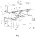
- FIG. 1 A machine tool 1 is shown, which is designed as a punch press.
- This machine tool 1 comprises a support structure with a closed machine frame 2. This comprises two horizontal frame legs 3, 4 and two vertical frame legs 5 and 6.
- the machine frame 2 encloses a frame interior 7 which defines the working area of the machine tool 1 forms with an upper tool 11 and a lower tool 9.
- the machine tool 1 is used to machine plate-shaped workpieces 10 which, for the sake of simplicity, in Figure 1 are not shown and can be arranged in the frame interior 7 for processing purposes.
- a workpiece 10 to be machined is placed on a workpiece support 8 provided in the frame interior 7.
- the lower tool 9 is mounted, for example in the form of a stamping die, on the lower horizontal frame leg 4 of the machine frame 2.
- This punch die can be provided with a die opening.
- the upper tool 11 which is designed as a punch, is immersed in the die opening of the lower tool designed as a punching die.
- the upper tool 11 and lower tool 9 can also be used as a bending punch and a bending die for forming workpieces 10 instead of a punch and a punching die.
- the upper tool 11 is fixed in a tool holder at a lower end of a plunger 12.
- the plunger 12 is part of a lifting drive device 13, by means of which the upper tool 11 can be moved in a lifting direction along a lifting axis 14.
- the stroke axis 14 runs in the direction of the Z axis of the coordinate system in FIG Figure 1 indicated numerical control 15 of the machine tool 1.
- the stroke drive device 13 Perpendicular to the stroke axis 14, the stroke drive device 13 can be moved along a positioning axis 16 in the direction of the double arrow.
- the positioning axis 16 runs in the direction of the Y direction of the coordinate system of the numerical control 15.
- the lifting drive device 13 receiving the upper tool 11 is moved along the positioning axis 16 by means of a motor drive 17.
- the movement of the plunger 12 along the stroke axis 14 and the positioning of the stroke drive device 13 along the positioning axis 16 take place by means of a motor drive 17 in the form of a Drive arrangement 17, in particular spindle drive arrangement, with a drive spindle 18 running in the direction of the positioning axis 16 and firmly connected to the machine frame 2.
- the linear drive device 13 is guided during movements along the positioning axis 16 on three guide rails 19 of the upper frame leg 3, of which in Figure 1 two guide rails 19 can be seen.
- One remaining guide rail 19 runs parallel to the visible guide rail 19 and is spaced from it in the direction of the X axis of the coordinate system of the numerical control 15.
- Guide shoes 20 of the lifting drive device 13 run on the guide rails 19.
- the mutual engagement of the guide rail 19 and the guide shoes 20 is such that this connection between the guide rails 19 and the guide shoes 20 can also absorb a load acting in the vertical direction. Accordingly, the lifting device 13 is suspended on the machine frame 2 via the guide shoes 20 and the guide rails 19. Another component of the lifting drive device 13 is a wedge gear 21, by means of which a position of the upper tool 11 relative to the lower tool 9 can be adjusted.
- the lower tool 9 is movably received along a lower positioning axis 25.
- This lower positioning axis 25 runs in the direction of the Y axis of the coordinate system of the numerical control 15.
- the lower positioning axis 25 is preferably aligned parallel to the upper positioning axis 16.
- the lower tool 9 can be moved directly on the lower positioning axis 16 with a motor drive arrangement 26 along the positioning axis 25.
- the lower tool 9 can also be provided on a lifting drive device 27 which can be moved along the lower positioning axis 25 by means of the motor drive arrangement 26.
- This drive arrangement 26 is preferably designed as a spindle drive arrangement.
- the lower lifting drive device 27 can correspond in structure to the upper lifting drive device 13.
- the motor drive arrangement 26 can also be the motor drive arrangement Drive arrangement 17 correspond.
- the lower lifting drive device 27 is also slidably mounted on a lower horizontal frame leg 4 associated guide rails 19.
- Guide shoes 20 of the lifting drive device 27 run on the guide rails 19, so that the connection between the guide rails 19 and guide shoes 20 on the lower tool 9 can also absorb a load acting in the vertical direction. Accordingly, the lifting drive device 27 is also suspended on the machine frame 2 via the guide shoes 20 and the guide rails 19 and at a distance from the guide rails 19 and guide shoes 20 of the upper lifting drive device 13.
- the lifting drive device 27 can also comprise a wedge gear 21, by means of which the position or height of the lower tool 9 can be adjusted along the Z axis.
- the numerical control 15 enables both the motor drives 17 for a movement of the upper tool 11 along the upper positioning axis 16 and the motor drive or motors 26 for a movement of the lower tool 9 along the lower positioning axis 25 to be controlled independently of one another.
- the upper and lower tools 11, 9 can thus be moved synchronously in the direction of the Y axis of the coordinate system. Likewise, an independent movement of the upper and lower tools 11, 9 can also be controlled in different directions. This independent movement of the upper and lower tool 11, 9 can be controlled at the same time. By decoupling the movement between the upper tool 11 and the lower tool 9, increased flexibility in the machining of workpieces 10 can be achieved.
- the upper and lower tools 11, 9 can also be designed in various ways for machining the workpieces 10.
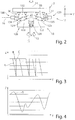
- a component of the lifting drive device 13 is the wedge gear 21, which in Figure 2 is shown.
- the wedge gear 21 comprises two wedge gear elements 122, 123 on the drive side and two wedge gear elements 124, 125 on the output side.
- the latter are structurally one Unit summarized in the form of an output-side double wedge 126.
- the tappet 12 On the output-side double wedge 126, the tappet 12 is rotatably mounted about the lifting axis 14.
- a motor-driven rotary drive device 128 is accommodated in the output-side double wedge 126 and, if necessary, moves the plunger 12 along the stroke axis 14. Both left and right rotation of the plunger 12 according to the double arrow in FIG Figure 2 possible.
- a plunger bearing 129 is shown schematically.
- the tappet bearing 129 allows low-friction rotary movements of the tappet 12 about the lifting axis 14, on the other hand the tappet bearing 129 supports the tappet 12 in the axial direction and accordingly carries loads which act on the tappet 12 in the direction of the lifting axis 14 into the output-side double wedge 126 from.
- the output-side double wedge 126 is delimited by a wedge surface 130 and by a wedge surface 131 of the output-side gear element 125.
- the wedge surfaces 130, 131 of the output-side wedge gear elements 124, 125 lie opposite wedge surfaces 132, 133 of the drive-side wedge gear elements 122, 123.
- Longitudinal guides 134, 135 guide the wedge gear element 122 on the drive side and the wedge gear element 124 on the output side, as well as the wedge gear element 123 on the drive side and the wedge gear element 125 on the output side in the direction of the Y axis, that is to say in the direction of the positioning axis 16 of the linear drive device 13, so as to be movable relative to one another.
- the drive-side wedge gear element 122 has a motor drive unit 138
- the drive-side wedge gear element 123 has a motor drive unit 139. Both drive units 138, 139 together form the spindle drive arrangement 17.
- the motor drive units 138, 139 have in common that in Figure 1 shown drive spindle 18 and the lifting drive device 13, 27 mounted on the machine frame 2 and consequently on the supporting structure side.
- the drive-side wedge gear elements 122, 123 are operated in such a way that these move, for example, towards one another along the positioning axis 16, which results in a relative movement between the drive-side wedge gear elements 122, 123 on the one hand and the output-side wedge gear elements 124, 125 on the other hand.
- the output-side double wedge 126 and the tappet 12 mounted thereon are moved downward along the stroke axis 14.
- the punch installed on the plunger 12 for example as the upper tool 11, performs a working stroke and thereby processes a workpiece 10 supported on the workpiece support 28, 29 or the workpiece support 8.
- the plunger 12 is in turn moved along the side by an opposite movement of the drive wedge elements 122, 123 Lift axis 14 raised or moved up.
- the above-described linear drive device 13 according to Figure 2 is preferably constructed identically as a lower lifting drive device 27 and receives the lower tool 9.
- FIG 3 a schematic diagram of a possible stroke movement of the plunger 12 is shown.
- the diagram shows a stroke along the Y-axis and the Z-axis.
- a superimposed actuation of a movement of the plunger 12 along the lifting axis 14 and along the positioning axis 16 can, for example, control an obliquely running lifting movement of the lifting plunger 12 downward towards the workpiece 10, as is represented by the first straight line A.
- the plunger 12 can, for example, be lifted vertically, as is represented by the straight line B.
- This is followed, for example, by an exclusive movement along the Y axis along the straight line C in order to position the ram 12 for a new working position relative to the workpiece 10.
- the work sequence described above can then be repeated, for example. If the workpiece 10 is moved on the workpiece support surface 28, 29 for a subsequent machining step, a movement along the straight line C can also be omitted.
- the in the diagram in Figure 3 possible stroke movement of the Ram 12 on the upper tool 11 is preferably combined with a stationary lower tool 9.
- the lower tool 9 is positioned within the machine frame 2 such that the upper and lower tools 11, 9 assume a defined position at the end of a working stroke of the upper tool 11.
- This exemplary superimposed stroke profile can be controlled both for the upper tool 11 and the lower tool 9.
- a superimposed lifting movement of the upper tool and / or lower tool 11, 9 can be controlled.
- Figure 4 a schematic diagram is shown, which represents a lifting movement of the plunger 12 according to the line D shown as an example along a Y-axis and a Z-axis.
- a stroke movement of the tappet 12 can run through a curve or an arc, in that an overlay of the movement movements in the Y direction and Z direction is controlled accordingly by the controller 15.
- Such flexible superimposition of the traversing movements in the X and Z directions enables specific machining tasks to be solved.
- the control of such a curve course can be provided for the upper tool 11 and / or lower tool 9.
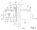
- FIG. 5 10 is a schematic view of the machine tool 1 according to FIG Figure 1 shown.
- a workpiece support 28, 29 extends laterally on the machine frame 2 of the machine tool 1.
- the workpiece support 28 can be assigned, for example, to a loading station (not shown in more detail) through which unworked workpieces 10 are placed on the workpiece support surface 28.
- Adjacent to the workpiece support surface 28, 29 is a feed device 22 which comprises a plurality of grippers 23 in order to grip the workpiece 10 placed on the workpiece support 28.
- the workpiece 10 is guided through the machine frame 2 in the X direction by means of the feed device 22.
- the Feed device 22 can also be driven in the Y direction. A free movement of the workpiece 10 in the XY plane can thereby be provided.
- the workpiece 10 can be movable both in the X direction and counter to the X direction by the feed device 22. This movement of the workpiece 10 can be adapted to a movement of the upper tool 11 and lower tool 9 in and against the Y direction for the respective machining task.
- the further workpiece support 29 is provided on the machine frame 2 opposite the workpiece support 28. This can be assigned to an unloading station, for example. Alternatively, the loading and unloading of the unmachined workpiece 10 and machined workpiece 10 with workpieces 81 can also be assigned to the same workpiece support 28, 29.
- the machine tool 1 can furthermore have a laser processing device 201, in particular a laser cutting machine, which is only schematically shown in a top view in FIG Figure 5 is shown.
- This laser processing device 201 can be designed, for example, as a CO 2 laser cutting machine.
- the laser processing device 201 comprises a laser source 202, which generates a laser beam 203, which is guided and focused in a laser processing head, in particular laser cutting head 206, by means of a schematically illustrated beam guide 204. Thereafter, the laser beam 204 is aligned perpendicular to the surface of the workpiece 10 by a cutting nozzle in order to machine the workpiece 10.
- the laser beam 203 acts on the workpiece 10 at the machining location, in particular the cutting location, preferably together with a process gas jet. The cutting point at which the laser beam 203 strikes the workpiece 10 is adjacent to the processing point of the upper tool 11 and lower tool 9.
- the laser cutting head 206 can be moved by a linear drive 207 with a linear axis system at least in the Y direction, preferably in the Y and Z direction.
- This linear axis system which the Receiving laser cutting head 206 can be assigned to the machine frame 2, attached to it or integrated therein.
- a beam passage opening can be provided in the workpiece support 28 below a working space of the laser cutting head 206.
- a beam collecting device for the laser beam 21 can preferably be provided below the beam passage opening.
- the beam passage opening and optionally the beam collecting device can also be designed as a structural unit.
- the laser processing device 201 can also have a solid-state laser as the laser source 202, the radiation of which is guided to the laser cutting head 206 with the aid of an optical fiber cable.
- the workpiece support 28, 29 can extend directly to the workpiece support 8, which at least partially surrounds the lower tool 9.
- the lower tool 9 can be moved along the lower positioning axis 25 in and against the Y direction within a free space that results therebetween.
- a machined workpiece 10 rests on the workpiece support 28, in which a workpiece part 81 is cut free from a cutting gap 83, for example by punching or by laser beam machining, except for a residual connection 82.
- the workpiece 81 is held in the workpiece 10 or the remaining residual grid by this residual connection.
- the workpiece 10 is positioned by means of the feed device 22 to the upper and lower tools 11, 9 for a punching and discharging step.
- the remaining connection 82 is separated by a punch stroke of the upper tool 11 to the lower tool 9.
- the workpiece part 81 can be removed, for example, by partially lowering the workpiece support 8 downwards.
- the cut-away workpiece part 81 can be transferred back to the workpiece support 28 or to the workpiece support 29 in order to unload the workpiece part 81 and the scrap skeleton.
- Small workpiece parts 81 can also be opened through an opening in the Lower tool 9 are removed.
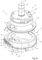
- the Figure 6 shows a perspective view of the tool 31 consisting of an upper tool 11, which is designed, for example, as a punch and from a lower tool 9, which is designed, for example, as a punching die.
- the upper tool 11 comprises a base body 33 with a clamping shaft 34 and an adjusting or indexing element or adjusting or indexing wedge 36.
- the clamping shaft 34 serves to hold the upper tool 11 in the upper tool holder on the machine side.
- the orientation of the upper tool 11 or the rotational position of the upper tool 11 is determined by the indexing wedge 36.
- the lower tool 9 likewise comprises a base body 41, which is suitable for being fixed in the lower tool holder on the machine side with a defined rotational position, for example by at least one adjusting element 42.
- the cutting tool 37 is provided on an underside of the base body 33 of the upper tool 11. This is, for example, round in cross section and thus has a circular cutting edge 38. Alternatively, it can be provided that the geometry of the cutting edge 38 is rectangular or square, or has a corresponding contour course.
- the cutting edge 38 can also be formed on an inclined cutting tool 37.
- the cutting tool 37 can also comprise a cutting edge 38 with a hollow grinding.
- the cutting tool 37 can have an end face 40. In the case of an inclined cutting tool 37, the end face 40 can also be inclined. In the case of a cutting tool 37 with a hollow grinding, the end face 40 is formed by the circumferential cutting edge 38. This faces the lower tool 9 and is preferably delimited by the cutting edge 38.
- the wiper 32 which has an opening, is assigned to the upper tool 11 39, which can correspond in geometry to the cutting edge 38.
- This stripper 32 is received in the upper machine-side tool holder by guides, such as pins 44, so that it can also be moved along the stroke axis 14 relative to the lower tool 9. In this way, for example, a workpiece 10 can be held down to the lower tool 9 as soon as the upper tool 11 is removed upward along the stroke axis 14.
- the stripper 32 can be moved simultaneously with the upper tool 11 along the stroke axis 14 and, after lifting off the lower tool 9, can perform a stripping movement.
- the lower tool 9 has an opening 46 in the base body 41, which opening is delimited by a circumferential contact surface 47.
- the support surface 47 can also extend only in sections or be formed by a plurality of elements.
- the opening 46 has a circular contour. This can also be designed differently from this.
- a cutting plate 49 is provided on the base body 41 of the lower tool 9. This cutting plate 49 is preferably designed to be detachable as a cutting insert. According to the first embodiment, this cutting plate 49 has an internal counter cutting edge 51 which is aligned and arranged towards the opening 46. Furthermore, the cutting plate 49 has an external counter cutting edge 52. The outer counter cutting edge 52 can be aligned with an outer side delimiting the bearing surface 47 or can be provided on this outer side.
- the inner counter-cutting edge and the outer counter-cutting edge 51, 52 are each formed on a separate cutting plate 49.
- the contact surface 47 can merge flush into the counter-cutting edge 51, 52.
- the counter cutting edge 51, 52 is preferably lower than the contact surface 47 in order to avoid damage, such as scratches, on the underside of the sheet metal.
- the counter cutting edge 51, 52 can also form an end face or a flat 57 or a protective strip 59 be aligned or protrude slightly.
- the contact surface 47 can be formed in an area adjacent to the cutting plate 49 such that the contact surface 47 corresponds at least to the length of the cutting plate 49 in the annular width.
- the inner counter cutting edge 51 is arranged on a protrusion 53 protruding in the direction of the opening 46.
- a discharge surface 55 is provided, which is assigned to the outer counter cutting edge 52.
- This discharge surface 55 is preferably inclined to the outside in a sloping manner with respect to the support surface 47.
- workpiece parts 81 which have been cut free can be discharged to the outside via the discharge surface 55 via the outside counter-cutting edge 52, for example in order to feed them to a collecting container or waste container.
- the discharge surface 55 is preferably exchangeably fastened to the base body 41 of the lower tool 9.
- the discharge surface 55 has a web section, not shown, which extends below the cutting plate 49, so that the discharge surface 55 is held in the base body 41 by clamping after the cutting plate 49 has been fastened.
- the discharge surface 55 is arranged recessed relative to the outer cutting edge 52 by a punching surface 56.
- the base body 41 of the lower tool 9 is flush with the punching surface 56 of the cutting plate 49 and has flats 57 that adjoin it laterally.
- the flats 59 are aligned tangentially to the opening 46.
- a run-up slope 58 is provided on the base body 41 of the lower tool 9. This run-up slope 58 flows smoothly into the bearing surface 47. This run-up slope 58 is limited by the flat 57.
- In a side view of the cutting surface 56 and outside Counter cutting edge 52 has a roof-shaped course. A radially outer edge of the ramp slope 58 is recessed with respect to the bearing surface 47.
- the run-up slope 58 extends from the outer counter-cutting edge 52 at least in an angular range of at least 30 ° with respect to the position axis 48.
- the run-up slope 58 preferably extends from the outer counter-cutting edge 52 by up to 90 °.
- Such a run-up bevel 58 makes it possible when moving the machined workpiece 10 with workpiece parts 81 held by residual connections 82 that they slide on the run-up bevel 58 onto the contact surface 47 of the lower tool 9 and thus prevent jamming with the counter-cutting edges 51, 52.
- the run-up slopes 58 can also be provided interchangeably on the base body 41.
- FIG 7 A first working position of the tool 31 is shown, in which the upper tool 11 with the cutting tool 37 is assigned to an outer counter cutting edge 52 of the lower tool 9.
- Figure 8 A perspective side view of a further working position of the tool 31 is shown, in which the cutting tool 37 of the upper tool 11 is aligned with the inner counter cutting edge 51 of the lower tool 9.
- FIG. 9 is a perspective view of an alternative Embodiment of the tool 31 for Figure 6 shown.
- an upper tool 11 is provided, which has a cutting tool 37 with a rectangular cutting edge 38.
- Such an upper tool 11 can also be used with a lower tool 9 according to FIG Figure 4 be used.
- the lower tool 9 in Figure 9 deviates from the lower tool 9 according to Figure 4 that the inner and outer counter cutting edges 51, 52 are formed separately from one another and that they are also offset in the angular position to the opening 46 on the base body 41.
- the inner counter-cutting edge 51 and the outer counter-cutting edge 52 are preferably arranged on the base body 41 offset by 180 ° to one another.
- the inner and outer counter cutting edges 51, 52 can also be aligned in other angular positions.
- a plurality of internal and / or external counter-cutting edges 51, 52 can also be provided on the lower tool 9.
- the number of inner and outer counter cutting edges 51, 52 can also differ from one another.
- Each of these cutting edges 38 and counter-cutting edges 51, 52 can have a different distance from the position axis 35, 48 of the respective upper tool 11 and lower tool 9.
- the inner and / or outer cutting edges 38 and counter-cutting edges 51, 52 can also have a closed contour.
- the inner counter cutting edge 51 is formed directly on the base body 41.
- the outer counter cutting edge 52 is releasably attached to the base body 41.
- the inside counter cutting edge 51 is assigned a run-up slope 58, for example. Alternatively or additionally, this run-up slope 58 can also be assigned to the outer counter cutting edge 52.
- FIG 10 is a perspective view of an alternative Embodiment of the lower tool 9 for a tool 31 according to Figure 6 shown.
- the inner counter-cutting edge 51 and the outer counter-cutting edge 52 are each designed as a releasable cutting plate 49. These are preferably also arranged separately from one another on the base body 41 or aligned with the support surface 47.
- the bevel 58 is attached to the base body 41 as a detachable attachment and the inner and outer counter-cutting edges 51, 52 are enclosed in the bevel 58.
- a protective strip 59 can be assigned to the outer cutting edge 52 on one or both sides, which is preferably held in a resilient manner.
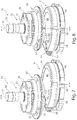
- FIGs 11 a and 11b is another alternative embodiment of the tool 31 to Figure 6 shown, the Figure 11 a a first working position and the Figure 11 b shows a second working position of the tool 31.
- the upper tool 11 is provided, that of the embodiment in FIG Figure 6 corresponds.
- the lower tool 9 deviates from the embodiment in FIG Figure 4 that the opening 46 is semicircular or arc segment-shaped.
- An outer counter cutting edge 52 can thereby be formed, which extends along the remaining diameter.
- the discharge surface 55 can be formed adjacent to the outer counter cutting edge 52.
- This embodiment has the advantage that a very long outer counter cutting edge 52 can be formed.
- a limitation of the opening 46 can be formed as an internal counter cutting edge 51.
- the upper tool 11 can be aligned with the lower tool 9 by a relative movement in the direction of travel along a workpiece plane of the upper tool 11 and / or the lower tool 9. Alternatively and / or additionally, a rotary movement of the upper tool 11 and / or the lower tool 9 can be superimposed.
- FIG 12 is another alternative embodiment of the Lower tool 9 for a tool 31 for Figure 6 shown.
- an internal counter cutting edge 51 is provided on the base body 41.
- This can also be designed as an insertable insert 49.
- an exchangeable adapter plate 61 with at least one outer counter cutting edge 52 is provided.
- the outer counter cutting edge 52 consists, for example, of three individual secondary cutting edges.
- the secondary cutting edges can be trapezoidal or otherwise aligned with one another.
- Such a lower tool 9 enables an increase in the flexibility with regard to the working position of the upper tool 11 to the outer counter cutting edge 52.
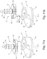
- FIGs 13 a to 13 d are different working positions in the plan view of the lower tool 9 according to Figure 12 shown with an example hexagonal cutting tool 37 of the upper tool 11.
- the Figure 13 a shows a working position in which a cutting edge 38 of the cutting tool 37 is assigned to the inner counter cutting edge 51.
- the Figure 13 b differs from Figure 13 a in that, for example, the lower tool 9 is rotated about its position axis 48 without the lower tool 9 having been moved in at least one direction of travel.
- the upper tool 11 can be aligned with the inner counter cutting edge 51 by a rotational movement about its position axis 35 and a possibly necessary movement along a positioning axis 16.
- the Figure 13 c shows a positioning of the cutting tool 37 of the upper tool 11 with respect to the outer counter cutting edge 52 of the lower tool 9, in particular in alignment with a secondary cutting edge. In this way, for example, a certain angular position for cutting the workpiece part 81 out of the workpiece 10 can be assumed.
- Figure 13 d is another alternative working position of the Cutting tool 37 of the upper tool 11 to the lower tool 9 shown. This is compared to Figure 13 c it can be seen that the cutting position can be changed in a simple manner by a corresponding alignment or rotation of the lower tool 9 about the position axis 48 and an assignment of the upper tool 11.
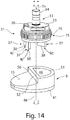
- Figure 14 12 is a perspective view of an alternative embodiment of tool 31 Figure 11 a and 11 b are shown.
- the lower tool 9 in this embodiment corresponds to that Figures 11 a and 11 b. In this respect, reference is made in full to this description of the figures.
- a punch which is designed as a multiple tool.
- Such a multiple tool comprises a plurality of cutting tools 37. These cutting tools 37 each have a cutting edge 38, these differing in shape and geometry from one another. These cutting tools 37 are received as stamp inserts in the base body 33.
- An activation device 75 is assigned to the base body 33 and has an external toothing 76, for example.
- a machine-side rotary drive which is preferably provided on the tool holder, activates a rotary movement of the activation device 75 about the position axis 35.
- This rotary movement has the effect that an internal pressure surface (not shown) assigned to the base body 33 of the activation device 75 is optional can be positioned to one of the cutting tools 37.
- an internal pressure surface (not shown) assigned to the base body 33 of the activation device 75 is optional can be positioned to one of the cutting tools 37.
- the one cutting tool 37 is positioned in a fixed manner relative to the base body 33, whereas the other cutting tools 37 can plunge into the base body 33 with a lifting movement along the lifting axis 14 and sitting on the workpiece 10 with increasing lifting movement.
- open contours can be cut in the workpiece 10.
- Such open contours can be, for example, a residual connection 82, such as a micro joint.
- individual workpiece parts 81 can be cut free from the workpiece 10 by one or more working strokes.
- such open contours can be formed by introducing a cutting gap 83, wherein several working strokes can be provided in order to form the cutting gap 83 or to punch out a waste part or good part as the workpiece part 81. Due to the independent movement of the upper tool 11 to the lower tool 9, with the same cutting tool 37 and the at least one counter cutting edge 51, 52, a simple adaptation to the thickness of the workpiece 10 to be machined can be provided.
Landscapes
- Engineering & Computer Science (AREA)
- Mechanical Engineering (AREA)
- Life Sciences & Earth Sciences (AREA)
- Forests & Forestry (AREA)
- Punching Or Piercing (AREA)
- Milling Processes (AREA)
Claims (24)
- Outil destiné à découper et/ou à former des pièces (10) en forme de plaque, en particulier des tôles,- pourvu d'un outil supérieur (11) et d'un outil inférieur (9) qui peuvent se déplacer l'un vers l'autre en vue d'usiner une pièce (10) disposée entre eux,- l'outil supérieur (11) comprenant au moins un outil de découpe (37) pourvu d'au moins une arête de découpe (38) et une tige de serrage (34), et ledit outil supérieur (11) présentant un axe de position (35),- l'outil inférieur (9) comprenant un corps de base (41) qui présente une surface d'appui (47) destinée à recevoir la pièce à usiner (10) et pourvue d'une ouverture (46) à laquelle est affectée une arête de contre-découpe intérieure (51) afin d'éjecter vers le bas, à travers l'ouverture (46), une partie de pièce (81) formée après l'opération de séparation, et ledit outil inférieur présentant un axe de position (48),- pourvu d'au moins une arête de contre-découpe extérieure (52) prévue à l'extérieur de l'ouverture (46) et affectée à la surface d'appui (47),
caractérisé en ce que- l'arête de contre-découpe extérieure (52) est orientée par rapport à une face extérieure de la surface d'appui (47) délimitant ladite surface d'appui (47),- un espacement de l'arête de contre-découpe extérieure (52) par rapport à l'axe de position (48) du corps de base (41) de l'outil inférieur (9) et un espacement de l'arête de contre-découpe intérieure (51) par rapport à l'axe de position (48) du corps de base (41) de l'outil inférieur (9) sont différents l'un de l'autre. - Outil selon la revendication 1, caractérisé en ce que la dimension de l'ouverture (46) ménagée dans le corps de base (41) de l'outil inférieur (9) est nettement plus grande, en particulier au moins 1,5 fois ou au moins deux fois plus grande, qu'une face frontale (40) dudit au moins un outil de découpe (37) de l'outil supérieur (11), en particulier qu'une face frontale de l'outil de découpe (37) de l'outil supérieur (11) qui plonge dans ladite ouverture (46).
- Outil selon l'une quelconque des revendications précédentes, caractérisé en ce que les arêtes de contre-découpe intérieure et extérieure (51, 52) sont réalisées respectivement en tant qu'arête de découpe ouverte.
- Outil selon la revendication 1, caractérisé en ce que les arêtes de contre-découpe intérieure et extérieure (51, 52) de l'outil inférieur (9) sont positionnées à l'opposé l'une de l'autre par rapport à la surface d'appui (47) et sont orientées l'une par rapport à l'autre sans décalage angulaire.
- Outil selon la revendication 1, caractérisé en ce que les arêtes de contre-découpe intérieure et extérieure (51, 52) de l'outil inférieur (9) sont orientées par rapport à la surface d'appui (47) de l'outil inférieur (9) de manière à être décalées l'une par rapport à l'autre selon un angle donné, en particulier décalées selon un angle de 180°.
- Outil selon l'une quelconque des revendications précédentes, caractérisé en ce que les arêtes de contre-découpe (51, 52) de l'outil inférieur (9) sont formées en tant qu'au moins une plaque de découpe (49) disposée de manière amovible sur le corps de base (41) de l'outil inférieur (9), ou en ce que les arêtes de contre-découpe (51, 52) sont réalisées sur le corps de base (41) lui-même.
- Outil selon l'une quelconque des revendications précédentes, caractérisé en ce que les arêtes de contre-découpe intérieure et extérieure (51, 52) sont prévues sur la même plaque de découpe (49).
- Outil selon l'une quelconque des revendications précédentes, caractérisé en ce qu'une surface de découpe (56) prolonge l'arête de contre-découpe intérieure et/ou extérieure (51, 52) à l'opposé de la surface d'appui (47) de l'outil inférieur (9) et de manière à être dirigée vers le bas.
- Outil selon l'une quelconque des revendications précédentes, caractérisé en ce qu'au moins une baguette de protection (59) est prévue de manière contiguë à ladite au moins une arête de contre-découpe (51, 52), et ce d'un seul côté ou des deux côtés.
- Outil selon l'une quelconque des revendications précédentes, caractérisé en ce que l'arête de contre-découpe intérieure (51) est formée de manière à pénétrer dans l'ouverture (46) et à faire saillie radialement vers l'intérieur par rapport à un bord de ladite ouverture.
- Outil selon l'une quelconque des revendications précédentes, caractérisé en ce qu'une arête délimitant l'ouverture (46) par rapport à la surface d'appui (47) de l'outil inférieur (9) est réalisée en tant qu'arête de contre-découpe intérieure (51).
- Outil selon l'une quelconque des revendications précédentes, caractérisé en ce que sur le corps de base (41) de l'outil inférieur (9) peuvent être fixées de manière amovible, en tant qu'au moins une arête de contre-découpe extérieure (52), une ou plusieurs arêtes de découpe auxiliaires qui sont orientées de manière à faire saillie par rapport au corps de base (41) et qui sont prévues de préférence sur une plaque d'adaptation (61) qui peut être fixée de manière amovible au corps de base (41).
- Outil selon l'une quelconque des revendications précédentes, caractérisé en ce que l'axe de position (48) de l'outil inférieur (9) se situe à l'intérieur de l'ouverture (46) ménagée dans le corps de base (41).
- Outil selon l'une quelconque des revendications précédentes, caractérisé en ce qu'à une arête de contre-découpe intérieure et/ou extérieure (51, 52) de l'outil inférieur (9) est affectée une surface d'éjection (55) qui, de préférence, est fixée de manière amovible au corps de base (41) de l'outil inférieur (9).
- Outil selon l'une quelconque des revendications précédentes, caractérisé en ce que les arêtes extérieures délimitant la surface d'appui (47) de l'outil inférieur (9) sont arrondies ou chanfreinées et/ou en ce que la surface d'appui (47) présente un plan de réception incliné (58) qui s'étend jusqu'à l'arête de contre-découpe extérieure (52).
- Outil selon l'une quelconque des revendications précédentes, caractérisé en ce que l'outil de découpe (37) de l'outil supérieur (11) est positionné de manière centrée ou de manière excentrée par rapport à l'axe de position (35).
- Outil selon l'une quelconque des revendications précédentes, caractérisé en ce que l'outil supérieur (11) présente plusieurs outils de découpe (37) et est réalisé en tant qu'outil multiple dans lequel les outils de découpe (37) peuvent être activés de manière individuelle par un dispositif d'activation (75) en vue de l'usinage de pièces.
- Machine-outil destinée à découper et/ou à former des pièces (10) en forme de plaque, de préférence des tôles,- pourvue d'un outil supérieur (11) qui peut être déplacé le long d'un axe de levage (14) grâce à un dispositif d'entraînement de levage (13) en direction d'une pièce (10) qui doit être usinée avec l'outil supérieur (11), voire en direction opposée, et qui peut être positionné le long d'un axe de position supérieur (16) s'étendant perpendiculairement à l'axe de levage (14) et qui peut être déplacé le long dudit axe de position supérieur (16) grâce à un mécanisme d'entraînement à moteur (17),- pourvue d'un outil inférieur (9) qui est orienté par rapport à l'outil supérieur (11) et qui peut être déplacé le long d'un axe de levage inférieur (30) grâce à un dispositif d'entraînement de levage (27) en direction de l'outil supérieur (11), voire en direction opposée, et qui peut être positionné le long d'un axe de position inférieur (25) qui est orienté perpendiculairement à l'axe de levage (14) de l'outil supérieur (11) et qui peut être déplacé le long de l'axe de position inférieur (25) grâce à un mécanisme de levage à moteur (26),- pourvue d'une commande (15) grâce à laquelle les mécanismes d'entraînement à moteur (17, 26) destinés à déplacer les outils supérieur et inférieur (11, 9) peuvent être activés, caractérisée en ce que- le mouvement de déplacement de l'outil supérieur (11) le long de l'axe de position supérieur (16) et le mouvement de déplacement de l'outil inférieur (9) le long de l'axe de position inférieur (25) peuvent être respectivement activés indépendamment l'un de l'autre, et- un outil (31) selon l'une quelconque des revendications 1 à 17 est prévu en vue de découper et/ou de former des pièces (10).
- Machine-outil selon la revendication 18, caractérisée en ce que la machine-outil (1) comprend un bâti de machine (2) en forme de C ou de forme fermée, l'outil supérieur (11) et l'outil inférieur (9) pouvant être déplacés dans l'espace intérieur dudit bâti de machine (2).
- Procédé destiné à découper et/ou à former des pièces (10) en forme de plaque, de préférence des tôles,- lors duquel un outil supérieur (11) qui peut être déplacé le long d'un axe de levage (14) grâce à un dispositif d'entraînement de levage (13) en direction d'une pièce (10) qui doit être usinée avec l'outil supérieur (11), voire dans la direction opposée, et qui peut être positionné le long d'un axe de position supérieur (16) s'étendant perpendiculairement à l'axe de levage (14) est déplacé le long dudit axe de position supérieur (16) grâce à un mécanisme d'entraînement à moteur (17),- lors duquel un outil inférieur (9) qui est orienté par rapport à l'outil supérieur (11) et qui peut être positionné le long d'un axe de levage inférieur (25) qui est orienté perpendiculairement à l'axe de levage (14) de l'outil supérieur (11) est déplacé le long dudit axe de position inférieur (25) grâce à un mécanisme de levage à moteur (26),- lors duquel les mécanismes d'entraînement à moteur (17, 26) destinés à déplacer les outils supérieur et inférieur (11, 9) sont activés par une commande (15),
caractérisé en ce que- un outil (31) selon l'une quelconque des revendications 1 à 17 est utilisé en vue d'usiner les pièces (10),- le mouvement de déplacement de l'outil supérieur (11) le long de l'axe de position supérieur (16) et le mouvement de déplacement de l'outil inférieur (9) le long de l'axe de position inférieur (25) sont respectivement activés indépendamment l'un de l'autre par la commande (15) . - Procédé selon la revendication 20, caractérisé en ce que pour orienter une fente de découpe dans la pièce (10) et/ou pour régler la largeur d'une fente de découpe entre l'arête de découpe (38) de l'outil supérieur (11) et l'arête de contre-découpe intérieure ou extérieure (51, 52) de l'outil inférieur (9),- l'outil supérieur (11) et/ou l'outil inférieur (9) sont réglés et sont orientés l'un par rapport à l'autre par un mouvement de rotation autour de leur axe de position respectif (35, 48), ou- l'outil supérieur (11) et/ou l'outil inférieur (9) sont déplacés le long de leur axe de position respectif (16, 25), ou- l'outil supérieur (11) et/ou l'outil inférieur (9) sont activés par combinaison du mouvement de rotation autour de leur axe de position respectif (35, 48) et du mouvement de déplacement le long des axes de position (16, 25).
- Procédé selon la revendication 20 ou 21, caractérisé en ce que l'outil supérieur (11) et l'outil inférieur (9) sont déplacés par un mouvement relatif de l'un par rapport à l'autre en vue de régler une largeur de fente de découpe ou d'obtenir une orientation par rapport au tracé d'une fente de découpe ou d'un lien résiduel.
- Procédé selon l'une quelconque des revendications 20 à 22, caractérisé en ce qu'une partie de pièce (81) est découpée en tant que partie utile ou en tant que partie résiduelle du fait de l'orientation de l'arête de découpe (38) de l'outil supérieur (11) par rapport à l'arête de contre-découpe extérieure (52) de l'outil inférieur (9) lorsque la dimension de ladite partie utile ou de ladite partie résiduelle est supérieure à l'ouverture (46) ménagée dans l'outil inférieur (9), et en ce que la partie utile ou la partie résiduelle dont la taille est inférieure à l'ouverture (46) ménagée dans l'outil inférieur (9) est découpée et est éjectée par l'ouverture (46) du fait de l'orientation de l'arête de découpe (38) de l'outil supérieur (11) par rapport à une arête de contre-découpe intérieure (51) de l'outil inférieur (9).
- Procédé selon l'une quelconque des revendications 20 à 23, caractérisé en ce que, lorsque la pièce (10) effectue un mouvement de déplacement entre l'outil supérieur (11) et l'outil inférieur (9), l'arête de contre-découpe extérieure et/ou intérieure (51, 52) de l'outil inférieur (9) tourne autour de l'axe de position (48) de l'outil inférieur (9) et est orientée de telle sorte que l'arête de contre-découpe (51, 52) de l'outil inférieur (9) se trouve orientée parallèlement au sens de déplacement de la pièce (10).
Priority Applications (1)
| Application Number | Priority Date | Filing Date | Title |
|---|---|---|---|
| PL17783413T PL3515622T3 (pl) | 2016-09-26 | 2017-09-26 | Narzędzie oraz obrabiarka, jak również sposób cięcia i/lub odkształcania przedmiotów obrabianych mających postać płyt |
Applications Claiming Priority (3)
| Application Number | Priority Date | Filing Date | Title |
|---|---|---|---|
| DE102016118175.7A DE102016118175B4 (de) | 2016-09-26 | 2016-09-26 | Werkzeugmaschine und Verfahren zum Bearbeiten von plattenförmigen Werkstücken |
| DE102016119434.4A DE102016119434A1 (de) | 2016-10-12 | 2016-10-12 | Werkzeug und Werkzeugmaschine sowie Verfahren zum Schneiden und/oder Umformen von plattenförmigen Werkstücken |
| PCT/EP2017/074296 WO2018055182A1 (fr) | 2016-09-26 | 2017-09-26 | Outil et machine-outil, ainsi que procédé de découpe et/ou de formage de pièces en forme de plaque |
Publications (2)
| Publication Number | Publication Date |
|---|---|
| EP3515622A1 EP3515622A1 (fr) | 2019-07-31 |
| EP3515622B1 true EP3515622B1 (fr) | 2020-07-15 |
Family
ID=60080759
Family Applications (1)
| Application Number | Title | Priority Date | Filing Date |
|---|---|---|---|
| EP17783413.2A Active EP3515622B1 (fr) | 2016-09-26 | 2017-09-26 | Outil et machine-outil, ainsi que procédé de découpe et/ou de formage de pièces en forme de plaque |
Country Status (6)
| Country | Link |
|---|---|
| US (1) | US11241727B2 (fr) |
| EP (1) | EP3515622B1 (fr) |
| JP (1) | JP7051825B2 (fr) |
| CN (1) | CN109789471B (fr) |
| PL (1) | PL3515622T3 (fr) |
| WO (1) | WO2018055182A1 (fr) |
Families Citing this family (3)
| Publication number | Priority date | Publication date | Assignee | Title |
|---|---|---|---|---|
| DE102019119848A1 (de) | 2019-07-23 | 2021-01-28 | Trumpf Werkzeugmaschinen Gmbh + Co. Kg | Werkzeug und Verfahren zum Bearbeiten von plattenförmigen Werkstücken, insbesondere Blechen |
| DE102019119849A1 (de) | 2019-07-23 | 2021-01-28 | Trumpf Werkzeugmaschinen Gmbh + Co. Kg | Werkzeug und Verfahren zum Bearbeiten von plattenförmigen Werkstücken |
| DE102019129787A1 (de) * | 2019-11-05 | 2021-05-06 | Trumpf Werkzeugmaschinen Gmbh + Co. Kg | Werkzeug und Verfahren zum Bearbeiten von plattenförmigen Werkstücken, insbesondere von Blechen |
Family Cites Families (41)
| Publication number | Priority date | Publication date | Assignee | Title |
|---|---|---|---|---|
| US522953A (en) * | 1894-07-10 | Die and process of making dies | ||
| US2035448A (en) * | 1932-08-05 | 1936-03-31 | Andersson Nils Fredrik Filemon | Apparatus for cutting sheet metal or the like |
| US2684717A (en) * | 1952-03-10 | 1954-07-27 | Tucker Smith G | Card perforating device |
| US3269240A (en) * | 1965-03-29 | 1966-08-30 | John S Killaly | Quadrant punch for turret punch presses and the like |
| US3370492A (en) * | 1965-04-02 | 1968-02-27 | Smithe Machine Co Inc F L | Die cutting presses |
| US3613491A (en) * | 1969-09-15 | 1971-10-19 | Manfred Kahmann | Punching machine |
| US3785236A (en) * | 1972-05-30 | 1974-01-15 | Hager & Sons Hinge Mfg | Impact die and carbide insert therefor |
| PL122194B1 (en) * | 1979-04-13 | 1982-06-30 | Politechnika Lodzka | Blanking die |
| US4343210A (en) * | 1979-05-31 | 1982-08-10 | Anritsu Electric Co Ltd | Punch press |
| DE3410913A1 (de) * | 1984-03-24 | 1985-10-03 | Trumpf GmbH & Co, 7257 Ditzingen | Werkzeugmaschine zur mechanischen und laserstrahl-bearbeitung eines werkstuecks |
| US4738173A (en) * | 1986-11-03 | 1988-04-19 | U.S. Amada Limited | Shearing in punch press and die therefor |
| US4929276A (en) * | 1989-05-22 | 1990-05-29 | Murata Wiedemann, Inc. | Multitool punch holder |
| JPH07108420B2 (ja) * | 1990-09-14 | 1995-11-22 | 株式会社小松製作所 | タレットパンチプレスの追切り加工方法 |
| US5195413A (en) * | 1991-08-16 | 1993-03-23 | Mate Punch & Die Co. | Shearing tool for punch presses |
| DE4235972A1 (de) | 1992-10-26 | 1994-04-28 | Pass Anlagenbau Gmbh | Schneid-Werkzeug, insbesondere für Stanz- und Nibbelautomaten |
| JP2597055Y2 (ja) * | 1993-07-19 | 1999-06-28 | 株式会社アマダ | パンチプレス |
| JP2611128B2 (ja) * | 1993-08-17 | 1997-05-21 | 株式会社アマダメトレックス | 追切り用切断金型 |
| US5392629A (en) * | 1993-10-26 | 1995-02-28 | Canoga Industries Inc. | Method and apparatus for forming multi-level features in an object |
| US6189361B1 (en) * | 1997-09-04 | 2001-02-20 | Amada Metrecs Company Limited | Tool for forming protrusions in material by cutting and deforming |
| JP2001524403A (ja) * | 1997-12-03 | 2001-12-04 | ピアレス マシーン アンド トゥール コーポレイション | 加圧紙カットインプレス・ダイ |
| US6125520A (en) * | 1999-04-19 | 2000-10-03 | Thyssen Elevator Holding Corporation | Shake and break process for sheet metal |
| JP2000343144A (ja) * | 1999-06-04 | 2000-12-12 | Denso Corp | プレス成形品の製造方法 |
| DE19954441A1 (de) * | 1999-08-13 | 2001-02-15 | Thyssenkrupp Ind Ag | Vorrichtung zur Betätigung eines Stößels in einer Hub- oder Spannvorrichtung, insbesondere zum Falzen von Blechen im Automobilbau |
| JP2001252726A (ja) | 2000-03-10 | 2001-09-18 | Murata Mach Ltd | 長尺材加工機 |
| GB2360727B (en) * | 2000-03-30 | 2004-02-04 | Tradewise Engineering Ltd | Modular unit for converting punching machines from single-punch to multiple-punch |
| JP2001321851A (ja) * | 2000-05-19 | 2001-11-20 | Amada Co Ltd | ダイ装置 |
| DE20020499U1 (de) * | 2000-12-02 | 2001-03-15 | Trumpf GmbH + Co., 71254 Ditzingen | Werkzeug zum Schlitzen von plattenartigen Werkstücken |
| JP4279532B2 (ja) * | 2002-10-01 | 2009-06-17 | 株式会社アマダ | 成形製品の加工方法に使用する金型装置及び下金型 |
| DE102006049046A1 (de) * | 2006-10-18 | 2008-04-24 | Trumpf Werkzeugmaschinen Gmbh + Co. Kg | Werkzeug und Werkzeugmaschine zum Bearbeiten von plattenartigen Werkstücken, insbesondere von Blechen |
| DE102006049044B4 (de) * | 2006-10-18 | 2018-01-11 | Trumpf Werkzeugmaschinen Gmbh + Co. Kg | Werkzeug zum Schneiden von plattenartigen Werkstücken |
| DE202008003915U1 (de) * | 2008-03-19 | 2008-05-29 | Trumpf Werkzeugmaschinen Gmbh + Co. Kg | Ausstoßwerkzeug zum Bearbeiten von Werkstücken |
| ATE515336T1 (de) * | 2008-10-20 | 2011-07-15 | Trumpf Werkzeugmaschinen Gmbh | Werkzeugmaschinen und verfahren zum ausschleusen eines werkstückteils |
| EP2196270B1 (fr) * | 2008-12-10 | 2014-05-07 | TRUMPF Werkzeugmaschinen GmbH + Co. KG | Système d'outillage avec inserts d'outils interchangeables pour machines de découpage / poinçonnage |
| DE202009004014U1 (de) | 2009-03-25 | 2009-06-04 | Trumpf Werkzeugmaschinen Gmbh + Co. Kg | Stanzwerkzeug und Werkzeugmaschine damit |
| ES2517390T3 (es) | 2011-05-26 | 2014-11-03 | Werkzeugmaschinen Gmbh + Co. Kg | Máquina herramienta en forma de prensa para el tratamiento de piezas de trabajo, especialmente de hojas de metal |
| JP6019821B2 (ja) * | 2012-07-02 | 2016-11-02 | 村田機械株式会社 | 追い抜き加工用金型 |
| JP2014018801A (ja) * | 2012-07-12 | 2014-02-03 | Honda Motor Co Ltd | 孔開け加工方法、孔を備えた構造体の製造方法および孔を備えた構造体 |
| DE102014205249B4 (de) * | 2014-03-20 | 2017-11-16 | Trumpf Werkzeugmaschinen Gmbh + Co. Kg | Werkzeug für eine Universalstanzmaschine, Universalstanzmaschine mit einem solchen Werkzeug sowie Verfahren zum Betreiben einer Universalstanzmaschine mit einem solchen Werkzeug |
| CN104259293B (zh) * | 2014-08-15 | 2016-05-04 | 宁波宏协承汽车部件有限公司 | 一种汽车门框中柱外板的冲压切割装置 |
| EP3269468A1 (fr) | 2015-06-19 | 2018-01-17 | TRUMPF Werkzeugmaschinen GmbH + Co. KG | Machine-outil de décharge des pièces d'ouvrage |
| WO2018055183A1 (fr) * | 2016-09-26 | 2018-03-29 | Trumpf Werkzeugmaschinen Gmbh + Co. Kg | Outil et machine-outil et procédé de traitement de pièces en forme de plaques |
-
2017
- 2017-09-26 CN CN201780059078.2A patent/CN109789471B/zh active Active
- 2017-09-26 JP JP2019515820A patent/JP7051825B2/ja active Active
- 2017-09-26 EP EP17783413.2A patent/EP3515622B1/fr active Active
- 2017-09-26 PL PL17783413T patent/PL3515622T3/pl unknown
- 2017-09-26 WO PCT/EP2017/074296 patent/WO2018055182A1/fr active Application Filing
-
2019
- 2019-03-25 US US16/363,167 patent/US11241727B2/en active Active
Non-Patent Citations (1)
| Title |
|---|
| None * |
Also Published As
| Publication number | Publication date |
|---|---|
| PL3515622T3 (pl) | 2021-01-11 |
| CN109789471A (zh) | 2019-05-21 |
| US11241727B2 (en) | 2022-02-08 |
| WO2018055182A1 (fr) | 2018-03-29 |
| US20190299272A1 (en) | 2019-10-03 |
| JP2019529123A (ja) | 2019-10-17 |
| JP7051825B2 (ja) | 2022-04-11 |
| EP3515622A1 (fr) | 2019-07-31 |
| CN109789471B (zh) | 2022-02-11 |
Similar Documents
| Publication | Publication Date | Title |
|---|---|---|
| EP1740327B1 (fr) | Procede pour ebavurer des bords de coupe sur des pieces | |
| WO2017202767A1 (fr) | Machine pour séparer par usinage une pièce sous forme de plaque et procédé pour éjecter une partie de pièce dégagée par découpe | |
| EP3515623B1 (fr) | Outil et machine-outil ainsi que procédé d'usinage de pièces en forme de plaque, en particulier de tôles | |
| WO2018055190A1 (fr) | Procédé, machine-outil et outil de découpage pour le découpage continu à course multiple de pièces en forme de plaque | |
| EP3515626B1 (fr) | Machine-outil et procédé d'usinage de pièces en forme de plaque | |
| EP3515622B1 (fr) | Outil et machine-outil, ainsi que procédé de découpe et/ou de formage de pièces en forme de plaque | |
| WO2018055183A1 (fr) | Outil et machine-outil et procédé de traitement de pièces en forme de plaques | |
| WO2018055184A1 (fr) | Outil et machine-outil ainsi que procédé d'usinage de pièces en forme de plaque, en particulier de tôles | |
| EP3515618B1 (fr) | Outil et machine-outil ainsi que procédé pour usiner des pièces en forme de panneaux | |
| EP3515617B1 (fr) | Outil et machine-outil ainsi que procédé d'usinage de pièces en forme de plaque | |
| DE102016120139B4 (de) | Verfahren, Werkzeugmaschine und Schlitzwerkzeug zum mehrhubig fortschreitenden Schlitzen von plattenförmigen Werkstücken | |
| DE102016119464B4 (de) | Werkzeug und Werkzeugmaschine sowie Verfahren zur Bearbeitung von plattenförmigen Werkstücken | |
| DE102016119435A1 (de) | Werkzeug und Werkzeugmaschine sowie Verfahren zum Bearbeiten von plattenförmigen Werkstücken | |
| DE102016120151A1 (de) | Verfahren und Werkzeugmaschine zum Bearbeiten von plattenförmigen Werkstücken, insbesondere von Blechen | |
| DE102006051245A1 (de) | Fertigungseinrichtung | |
| DE102016120141B3 (de) | Werkzeug und Werkzeugmaschine sowie Verfahren zum Bearbeiten von plattenförmigen Werkstücken | |
| DE102016119457A1 (de) | Werkzeug und Werkzeugmaschine sowie Verfahren zur Bearbeitung von plattenförmigen Werkstücken | |
| WO2021013810A1 (fr) | Outil et procédé pour l'usinage de pièces en forme de plaques, en particulier de tôles | |
| WO2018055178A1 (fr) | Procédé et machine-outil servant à l'usinage de pièces en forme de plaque, en particulier de tôles | |
| DE102016119434A1 (de) | Werkzeug und Werkzeugmaschine sowie Verfahren zum Schneiden und/oder Umformen von plattenförmigen Werkstücken | |
| WO2018055185A1 (fr) | Machine-outil et procédé d'usinage de pièces en forme de plaque | |
| DE102016120035B3 (de) | Werkzeug und Werkzeugmaschine sowie Verfahren zum Bearbeiten von plattenförmigen Werkstücken | |
| WO2021013806A1 (fr) | Outil et procédé pour l'usinage de pièces sous forme de plaques | |
| EP1459815B1 (fr) | Dispositif de pliage, en particulier pour des materiaux de profile en tôle |
Legal Events
| Date | Code | Title | Description |
|---|---|---|---|
| STAA | Information on the status of an ep patent application or granted ep patent |
Free format text: STATUS: UNKNOWN |
|
| STAA | Information on the status of an ep patent application or granted ep patent |
Free format text: STATUS: THE INTERNATIONAL PUBLICATION HAS BEEN MADE |
|
| PUAI | Public reference made under article 153(3) epc to a published international application that has entered the european phase |
Free format text: ORIGINAL CODE: 0009012 |
|
| STAA | Information on the status of an ep patent application or granted ep patent |
Free format text: STATUS: REQUEST FOR EXAMINATION WAS MADE |
|
| 17P | Request for examination filed |
Effective date: 20190426 |
|
| AK | Designated contracting states |
Kind code of ref document: A1 Designated state(s): AL AT BE BG CH CY CZ DE DK EE ES FI FR GB GR HR HU IE IS IT LI LT LU LV MC MK MT NL NO PL PT RO RS SE SI SK SM TR |
|
| AX | Request for extension of the european patent |
Extension state: BA ME |
|
| RIN1 | Information on inventor provided before grant (corrected) |
Inventor name: MAATZ, MARKUS Inventor name: KLINKHAMMER, MARC Inventor name: KAPPES, JENS Inventor name: HANK, RAINER Inventor name: NEUPERT, JOERG Inventor name: TRAENKLEIN, DENNIS Inventor name: JAKISCH, CHRISTIAN Inventor name: SCHINDEWOLF, LEONARD Inventor name: OCKENFUSS, SIMON Inventor name: WILHELM, MARKUS Inventor name: TATARCZYK, ALEXANDER Inventor name: BITTO, DOMINIK |
|
| DAV | Request for validation of the european patent (deleted) | ||
| DAX | Request for extension of the european patent (deleted) | ||
| GRAP | Despatch of communication of intention to grant a patent |
Free format text: ORIGINAL CODE: EPIDOSNIGR1 |
|
| STAA | Information on the status of an ep patent application or granted ep patent |
Free format text: STATUS: GRANT OF PATENT IS INTENDED |
|
| INTG | Intention to grant announced |
Effective date: 20200318 |
|
| GRAS | Grant fee paid |
Free format text: ORIGINAL CODE: EPIDOSNIGR3 |
|
| GRAA | (expected) grant |
Free format text: ORIGINAL CODE: 0009210 |
|
| STAA | Information on the status of an ep patent application or granted ep patent |
Free format text: STATUS: THE PATENT HAS BEEN GRANTED |
|
| AK | Designated contracting states |
Kind code of ref document: B1 Designated state(s): AL AT BE BG CH CY CZ DE DK EE ES FI FR GB GR HR HU IE IS IT LI LT LU LV MC MK MT NL NO PL PT RO RS SE SI SK SM TR |
|
| REG | Reference to a national code |
Ref country code: CH Ref legal event code: EP Ref country code: GB Ref legal event code: FG4D Free format text: NOT ENGLISH |
|
| REG | Reference to a national code |
Ref country code: IE Ref legal event code: FG4D Free format text: LANGUAGE OF EP DOCUMENT: GERMAN |
|
| REG | Reference to a national code |
Ref country code: DE Ref legal event code: R096 Ref document number: 502017006264 Country of ref document: DE |
|
| REG | Reference to a national code |
Ref country code: AT Ref legal event code: REF Ref document number: 1290420 Country of ref document: AT Kind code of ref document: T Effective date: 20200815 |
|
| REG | Reference to a national code |
Ref country code: LT Ref legal event code: MG4D |
|
| REG | Reference to a national code |
Ref country code: NL Ref legal event code: MP Effective date: 20200715 |
|
| PG25 | Lapsed in a contracting state [announced via postgrant information from national office to epo] |
Ref country code: FI Free format text: LAPSE BECAUSE OF FAILURE TO SUBMIT A TRANSLATION OF THE DESCRIPTION OR TO PAY THE FEE WITHIN THE PRESCRIBED TIME-LIMIT Effective date: 20200715 Ref country code: PT Free format text: LAPSE BECAUSE OF FAILURE TO SUBMIT A TRANSLATION OF THE DESCRIPTION OR TO PAY THE FEE WITHIN THE PRESCRIBED TIME-LIMIT Effective date: 20201116 Ref country code: LT Free format text: LAPSE BECAUSE OF FAILURE TO SUBMIT A TRANSLATION OF THE DESCRIPTION OR TO PAY THE FEE WITHIN THE PRESCRIBED TIME-LIMIT Effective date: 20200715 Ref country code: BG Free format text: LAPSE BECAUSE OF FAILURE TO SUBMIT A TRANSLATION OF THE DESCRIPTION OR TO PAY THE FEE WITHIN THE PRESCRIBED TIME-LIMIT Effective date: 20201015 Ref country code: ES Free format text: LAPSE BECAUSE OF FAILURE TO SUBMIT A TRANSLATION OF THE DESCRIPTION OR TO PAY THE FEE WITHIN THE PRESCRIBED TIME-LIMIT Effective date: 20200715 Ref country code: GR Free format text: LAPSE BECAUSE OF FAILURE TO SUBMIT A TRANSLATION OF THE DESCRIPTION OR TO PAY THE FEE WITHIN THE PRESCRIBED TIME-LIMIT Effective date: 20201016 Ref country code: NO Free format text: LAPSE BECAUSE OF FAILURE TO SUBMIT A TRANSLATION OF THE DESCRIPTION OR TO PAY THE FEE WITHIN THE PRESCRIBED TIME-LIMIT Effective date: 20201015 Ref country code: HR Free format text: LAPSE BECAUSE OF FAILURE TO SUBMIT A TRANSLATION OF THE DESCRIPTION OR TO PAY THE FEE WITHIN THE PRESCRIBED TIME-LIMIT Effective date: 20200715 Ref country code: SE Free format text: LAPSE BECAUSE OF FAILURE TO SUBMIT A TRANSLATION OF THE DESCRIPTION OR TO PAY THE FEE WITHIN THE PRESCRIBED TIME-LIMIT Effective date: 20200715 |
|
| PG25 | Lapsed in a contracting state [announced via postgrant information from national office to epo] |
Ref country code: LV Free format text: LAPSE BECAUSE OF FAILURE TO SUBMIT A TRANSLATION OF THE DESCRIPTION OR TO PAY THE FEE WITHIN THE PRESCRIBED TIME-LIMIT Effective date: 20200715 Ref country code: RS Free format text: LAPSE BECAUSE OF FAILURE TO SUBMIT A TRANSLATION OF THE DESCRIPTION OR TO PAY THE FEE WITHIN THE PRESCRIBED TIME-LIMIT Effective date: 20200715 Ref country code: IS Free format text: LAPSE BECAUSE OF FAILURE TO SUBMIT A TRANSLATION OF THE DESCRIPTION OR TO PAY THE FEE WITHIN THE PRESCRIBED TIME-LIMIT Effective date: 20201115 |
|
| PG25 | Lapsed in a contracting state [announced via postgrant information from national office to epo] |
Ref country code: NL Free format text: LAPSE BECAUSE OF FAILURE TO SUBMIT A TRANSLATION OF THE DESCRIPTION OR TO PAY THE FEE WITHIN THE PRESCRIBED TIME-LIMIT Effective date: 20200715 |
|
| REG | Reference to a national code |
Ref country code: DE Ref legal event code: R097 Ref document number: 502017006264 Country of ref document: DE |
|
| PG25 | Lapsed in a contracting state [announced via postgrant information from national office to epo] |
Ref country code: SM Free format text: LAPSE BECAUSE OF FAILURE TO SUBMIT A TRANSLATION OF THE DESCRIPTION OR TO PAY THE FEE WITHIN THE PRESCRIBED TIME-LIMIT Effective date: 20200715 Ref country code: EE Free format text: LAPSE BECAUSE OF FAILURE TO SUBMIT A TRANSLATION OF THE DESCRIPTION OR TO PAY THE FEE WITHIN THE PRESCRIBED TIME-LIMIT Effective date: 20200715 Ref country code: RO Free format text: LAPSE BECAUSE OF FAILURE TO SUBMIT A TRANSLATION OF THE DESCRIPTION OR TO PAY THE FEE WITHIN THE PRESCRIBED TIME-LIMIT Effective date: 20200715 Ref country code: DK Free format text: LAPSE BECAUSE OF FAILURE TO SUBMIT A TRANSLATION OF THE DESCRIPTION OR TO PAY THE FEE WITHIN THE PRESCRIBED TIME-LIMIT Effective date: 20200715 Ref country code: CZ Free format text: LAPSE BECAUSE OF FAILURE TO SUBMIT A TRANSLATION OF THE DESCRIPTION OR TO PAY THE FEE WITHIN THE PRESCRIBED TIME-LIMIT Effective date: 20200715 |
|
| REG | Reference to a national code |
Ref country code: CH Ref legal event code: PL |
|
| PLBE | No opposition filed within time limit |
Free format text: ORIGINAL CODE: 0009261 |
|
| STAA | Information on the status of an ep patent application or granted ep patent |
Free format text: STATUS: NO OPPOSITION FILED WITHIN TIME LIMIT |
|
| PG25 | Lapsed in a contracting state [announced via postgrant information from national office to epo] |
Ref country code: AL Free format text: LAPSE BECAUSE OF FAILURE TO SUBMIT A TRANSLATION OF THE DESCRIPTION OR TO PAY THE FEE WITHIN THE PRESCRIBED TIME-LIMIT Effective date: 20200715 |
|
| REG | Reference to a national code |
Ref country code: BE Ref legal event code: MM Effective date: 20200930 |
|
| 26N | No opposition filed |
Effective date: 20210416 |
|
| PG25 | Lapsed in a contracting state [announced via postgrant information from national office to epo] |
Ref country code: LU Free format text: LAPSE BECAUSE OF NON-PAYMENT OF DUE FEES Effective date: 20200926 Ref country code: SK Free format text: LAPSE BECAUSE OF FAILURE TO SUBMIT A TRANSLATION OF THE DESCRIPTION OR TO PAY THE FEE WITHIN THE PRESCRIBED TIME-LIMIT Effective date: 20200715 |
|
| PG25 | Lapsed in a contracting state [announced via postgrant information from national office to epo] |
Ref country code: SI Free format text: LAPSE BECAUSE OF FAILURE TO SUBMIT A TRANSLATION OF THE DESCRIPTION OR TO PAY THE FEE WITHIN THE PRESCRIBED TIME-LIMIT Effective date: 20200715 Ref country code: LI Free format text: LAPSE BECAUSE OF NON-PAYMENT OF DUE FEES Effective date: 20200930 Ref country code: IE Free format text: LAPSE BECAUSE OF NON-PAYMENT OF DUE FEES Effective date: 20200926 Ref country code: CH Free format text: LAPSE BECAUSE OF NON-PAYMENT OF DUE FEES Effective date: 20200930 Ref country code: BE Free format text: LAPSE BECAUSE OF NON-PAYMENT OF DUE FEES Effective date: 20200930 |
|
| PGFP | Annual fee paid to national office [announced via postgrant information from national office to epo] |
Ref country code: FR Payment date: 20210922 Year of fee payment: 5 |
|
| PGFP | Annual fee paid to national office [announced via postgrant information from national office to epo] |
Ref country code: PL Payment date: 20210819 Year of fee payment: 5 |
|
| PG25 | Lapsed in a contracting state [announced via postgrant information from national office to epo] |
Ref country code: TR Free format text: LAPSE BECAUSE OF FAILURE TO SUBMIT A TRANSLATION OF THE DESCRIPTION OR TO PAY THE FEE WITHIN THE PRESCRIBED TIME-LIMIT Effective date: 20200715 Ref country code: MT Free format text: LAPSE BECAUSE OF FAILURE TO SUBMIT A TRANSLATION OF THE DESCRIPTION OR TO PAY THE FEE WITHIN THE PRESCRIBED TIME-LIMIT Effective date: 20200715 Ref country code: CY Free format text: LAPSE BECAUSE OF FAILURE TO SUBMIT A TRANSLATION OF THE DESCRIPTION OR TO PAY THE FEE WITHIN THE PRESCRIBED TIME-LIMIT Effective date: 20200715 |
|
| PG25 | Lapsed in a contracting state [announced via postgrant information from national office to epo] |
Ref country code: MK Free format text: LAPSE BECAUSE OF FAILURE TO SUBMIT A TRANSLATION OF THE DESCRIPTION OR TO PAY THE FEE WITHIN THE PRESCRIBED TIME-LIMIT Effective date: 20200715 Ref country code: MC Free format text: LAPSE BECAUSE OF FAILURE TO SUBMIT A TRANSLATION OF THE DESCRIPTION OR TO PAY THE FEE WITHIN THE PRESCRIBED TIME-LIMIT Effective date: 20200715 |
|
| PG25 | Lapsed in a contracting state [announced via postgrant information from national office to epo] |
Ref country code: FR Free format text: LAPSE BECAUSE OF NON-PAYMENT OF DUE FEES Effective date: 20220930 |
|
| PGFP | Annual fee paid to national office [announced via postgrant information from national office to epo] |
Ref country code: GB Payment date: 20230920 Year of fee payment: 7 |
|
| REG | Reference to a national code |
Ref country code: AT Ref legal event code: MM01 Ref document number: 1290420 Country of ref document: AT Kind code of ref document: T Effective date: 20220926 |
|
| PGFP | Annual fee paid to national office [announced via postgrant information from national office to epo] |
Ref country code: DE Payment date: 20230920 Year of fee payment: 7 |
|
| PG25 | Lapsed in a contracting state [announced via postgrant information from national office to epo] |
Ref country code: AT Free format text: LAPSE BECAUSE OF NON-PAYMENT OF DUE FEES Effective date: 20220926 |
|
| PGFP | Annual fee paid to national office [announced via postgrant information from national office to epo] |
Ref country code: IT Payment date: 20230927 Year of fee payment: 7 |
|
| PG25 | Lapsed in a contracting state [announced via postgrant information from national office to epo] |
Ref country code: PL Free format text: LAPSE BECAUSE OF NON-PAYMENT OF DUE FEES Effective date: 20220926 |