EP2176552B1 - Exzenterschneckenpumpe mit geteiltem stator - Google Patents
Exzenterschneckenpumpe mit geteiltem stator Download PDFInfo
- Publication number
- EP2176552B1 EP2176552B1 EP08785517A EP08785517A EP2176552B1 EP 2176552 B1 EP2176552 B1 EP 2176552B1 EP 08785517 A EP08785517 A EP 08785517A EP 08785517 A EP08785517 A EP 08785517A EP 2176552 B1 EP2176552 B1 EP 2176552B1
- Authority
- EP
- European Patent Office
- Prior art keywords
- stator
- progressive cavity
- cavity pump
- pump according
- jacket
- Prior art date
- Legal status (The legal status is an assumption and is not a legal conclusion. Google has not performed a legal analysis and makes no representation as to the accuracy of the status listed.)
- Active
Links
Images


Classifications
-
- F—MECHANICAL ENGINEERING; LIGHTING; HEATING; WEAPONS; BLASTING
- F04—POSITIVE - DISPLACEMENT MACHINES FOR LIQUIDS; PUMPS FOR LIQUIDS OR ELASTIC FLUIDS
- F04C—ROTARY-PISTON, OR OSCILLATING-PISTON, POSITIVE-DISPLACEMENT MACHINES FOR LIQUIDS; ROTARY-PISTON, OR OSCILLATING-PISTON, POSITIVE-DISPLACEMENT PUMPS
- F04C2/00—Rotary-piston machines or pumps
- F04C2/08—Rotary-piston machines or pumps of intermeshing-engagement type, i.e. with engagement of co-operating members similar to that of toothed gearing
- F04C2/10—Rotary-piston machines or pumps of intermeshing-engagement type, i.e. with engagement of co-operating members similar to that of toothed gearing of internal-axis type with the outer member having more teeth or tooth-equivalents, e.g. rollers, than the inner member
- F04C2/107—Rotary-piston machines or pumps of intermeshing-engagement type, i.e. with engagement of co-operating members similar to that of toothed gearing of internal-axis type with the outer member having more teeth or tooth-equivalents, e.g. rollers, than the inner member with helical teeth
- F04C2/1071—Rotary-piston machines or pumps of intermeshing-engagement type, i.e. with engagement of co-operating members similar to that of toothed gearing of internal-axis type with the outer member having more teeth or tooth-equivalents, e.g. rollers, than the inner member with helical teeth the inner and outer member having a different number of threads and one of the two being made of elastic materials, e.g. Moineau type
- F04C2/1073—Rotary-piston machines or pumps of intermeshing-engagement type, i.e. with engagement of co-operating members similar to that of toothed gearing of internal-axis type with the outer member having more teeth or tooth-equivalents, e.g. rollers, than the inner member with helical teeth the inner and outer member having a different number of threads and one of the two being made of elastic materials, e.g. Moineau type where one member is stationary while the other member rotates and orbits
- F04C2/1075—Construction of the stationary member
Definitions
- the invention relates to an eccentric screw pump with at least one stator made of an elastic material and a rotor mounted in the stator, wherein the stator is at least partially surrounded by a stator casing or stator housing.
- the rotor is regularly connected to the drive or the drive shaft via at least one coupling rod, which is also referred to as a cardan shaft.
- the pump has a suction housing and a connection piece, wherein the stator is connected at one end to a connection flange of the suction housing and the other end to a connection flange of the connection piece.
- Elastic material in the context of the invention means in particular an elastomer, e.g. a (synthetic) rubber or a rubber mixture.
- composites of an elastomer or other material, e.g. Metal includes.
- the elastic stator is formed into a stator jacket of e.g. Metal is vulcanised.
- the elastomeric stators are subject to wear during operation, so that at regular intervals maintenance or a stator replacement is required.
- the stators are often replaced with their molded stator covers.
- stator For cost reasons and also for reasons of environmental protection, it has therefore been proposed in practice to manufacture the elastomeric stator on the one hand and the stator jacket or stator housing made of metal on the other as separate components.
- the stator can then be inserted in the course of assembly in the cylindrical stator shell made of metal, so that after appropriate wear only the stator replaced and used the stator case again can be.
- stators are also referred to as a push-in.
- the assembly of such a slide-in stator is often expensive in practice and associated with extensive disassembly of the eccentric screw pump.
- the invention has for its object to provide an eccentric screw pump of the type described above, which allows replacement of the elastic stator in a cost effective and simple assembly technique.
- the stator consists of a longitudinally divided stator of at least two stator sub-shells. It is preferably two stator shells, which are thus designed as half shells and each cover an angle of 180 °.
- the invention also includes split stators with three, four or more sub-shells, which then each cover an angle of 120 ° or 90 ° or less.
- the invention is initially based on the recognition that it is expedient to produce the elastomeric stator as a separate component from the stator shell or stator housing to ensure replacement of only the elastomeric component and a reusability of the stator shell.
- the exchange can be done without a costly disassembly of the pump is necessary.
- the pump can remain mounted in its basic structure on eg a base plate or mounting plate.
- the suction housing on the one hand and the connection piece on the other as well as the rotor can remain mounted.
- the two half shells or the plurality of partial shells can then be mounted as it were around the rotor.
- the stator is connected with its ends, on the one hand, to a connection flange of the suction housing and, on the other hand, to a connecting flange of the connecting piece, wherein the separate partial shells - as explained - can be mounted individually, without disassembly of the pump being required.
- the partial shells are elastically deformable and therefore are kinkable or bendable for insertion. It may be expedient not to mount the stator or the stator shells directly to the connection flanges, but to provide adapter pieces which are connected to the one or more connection flanges.
- annular adapter pieces are adapted to the geometry of the stator or the stator partial shells, so that with the help of the adapter pieces in principle also has the possibility of using the longitudinally divided stator according to the invention in connection with conventional pump housings or suction housings and connecting pieces.
- the adapters can also be referred to as centering rings.
- stator or the stator partial shells with end sealing surfaces can each be plugged into a stator receptacle of the corresponding connection flange or of the corresponding adapter piece or can be plugged onto such.
- the stator at the end has conical, preferably outer-conical or inner-conical sealing surfaces, while the described stator receptacles of the connecting flanges or adapter pieces have conical, preferably inner-conical or outer-conical sealing counter surfaces.
- the end-side sealing surfaces of the stator are formed externally conical and they then abut against the inner-conical sealing mating surfaces of the stator.
- the stator has end-to-end conical sealing surfaces, and the stator receptacles on the connection flange or on the adapter piece have outer-conical sealing opposing surfaces.
- stator receptacle protrudes, as it were, in the axial or axially parallel direction from the connection flange or the adapter piece, so that the stator receptacle engages in the stator end or the stator is plugged onto the stator receptacle.
- the cone angle of the sealing surfaces or the sealing counter surfaces may be 10 ° to 50 °, preferably 20 ° to 30 °.
- stator casing is designed as a longitudinally divided casing and has for this purpose at least two, preferably at least four casing segments.
- This also contributes to the fact that the wearing part forming elastomeric stator can be replaced without major disassembly, because even the multi-part stator jacket can now be dismantled without the suction housing, discharge nozzle and / or rotor must be removed from its installed position.
- a longitudinally divided stator jacket with its several shell segments at the same time forms a stator-clamping device or stator adjustment device with which the stator can be tensioned against the rotor, in particular in the radial direction.
- the invention is based on the recognition that the elastomeric stator is usually mounted with respect to the rotatably driven rotor with a bias, wherein the function of the eccentric screw pump depends substantially on this bias.
- the simple structure and in particular the simple replacement of the stator can now be the desired Vorspannure set excellent and in particular set up a post-tension with appropriate wear.
- the tightness of the longitudinally divided stator is ensured by the multi-part clamping device.
- the stator clamping device ensures not only a sufficient tightness or connection of the two stator sub-shells to each other, but also a tight connection or a tight engagement of the stator ends in the corresponding stator receptacles of the connecting flanges or adapters.
- the invention proposes that the outer side abutting against the stator shroud segments have, for example, end mounting flanges for attachment to the flange or adapter piece. These mounting flanges can be connected to the connection flange or the adapter piece with clamping devices for the purpose of clamping the stator.
- the clamping means can be designed as screw devices, so that can be adjusted in a simple manner, the desired bias or adjusted.
- the shroud segments are adapted with their mounting flanges to the geometry of the stator and the connecting flanges or adapter pieces, that the fastening of the mounting flanges on the connecting flanges or adapter pieces to form an adjustable annular gap.
- This can be a gap width of up to 10 mm, preferably up to 5 mm. It may therefore be expedient to mount the mounting flanges first with a gap width of, for example, 5 mm, so that then a residual tension of a total of 5 mm clamping path can take place when wear occurs.
- the mounting flanges can overlap or engage in the connection flange or the adapter piece.
- stator subshells each have at least one antirotation protruding on the outside.
- an anti-rotation can be connected as a longitudinal ridge on the outside of the stator subshells, for example.
- the geometry of the stator shells with their longitudinal webs is preferably adapted to the geometry of the plurality of shroud segments, so that engage in the invention, the longitudinal webs forming the rotation in corresponding spaces between two adjacent shroud segments.
- these webs may also have end stops, which serve as axial securing and abut against the adapter pieces or connecting flanges.
- stator according to the invention can be easily mounted and replaced, without, e.g. Pressure nozzle or pressure lines must be solved.
- the required rotor-stator clamp can be easily adjusted.
- the stator can be easily manufactured in relation to the dimensions of the stator geometry, since exact dimensional accuracy is no longer required.
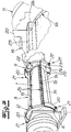
- an eccentric screw pump which in its basic structure has a stator 1 made of an elastic material and a rotor 2 mounted in the stator 1, wherein the stator 1 is surrounded at least in regions by a stator shell 3. Furthermore, the pump has a suction housing 4 and a connection piece 5, which is also referred to as a discharge nozzle. Not shown is also provided drive, wherein the drive operates on the rotor 2 via a merely indicated coupling rod 6. The coupling rod is connected via coupling joints on the one hand to the rotor 2 and on the other hand to the drive shaft, not shown, wherein of the coupling joints only the rotor-side hinge 7 is shown.
- the pump is usually mounted on a merely indicated base plate 8, which may be a base plate supplied with the pump or a base plate provided by the user.
- the stator 1 is connected in a conventional manner with its one end to a connecting flange 9 of the suction housing 4 and with its other end to a connecting flange 10 of the connecting piece 5.
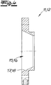
- the connection in the illustrated embodiment is not directly to these connection flanges 9, 10, but with the interposition of an adapter piece 11, 12, whose structure will be explained in more detail below.
- These adapters are also referred to as centering rings.
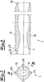
- stator 1 is now formed as a longitudinally divided stator and consists of two stator-part shells 1 a, 1 b, which form half-shells in the embodiment, each covering an angle of 180 °.
- Longitudinal means means along the stator longitudinal axis L or parallel to this. The separating cut between the partial shells consequently runs along or parallel to the longitudinal axis L.
- This longitudinally divided configuration of the elastomeric stator makes it possible to disassemble and mount the stator 1 with the suction housing 4, discharge nozzle 5 and rotor 2 mounted, since the stator 1 does not, as in the prior art, e.g. must be pushed from one side onto the rotor 2 after removing the pressure port 5.
- stator 1 and its stator shells 1 a, 1 b end sealing surfaces 13, 14 (or 13 ', 14') on.
- the stator partial shells 1a, 1b are then (successively) with their end-side sealing surfaces 13, 14 in Statorfactn 15, 16 inserted or with sealing surfaces 13 ', 14' on such Statorabilityn 15 ', 16' attachable, said Statorfactn in the here illustrated embodiment with adapter pieces on these adapter pieces 11, 12 are provided.
- the adapter pieces 11, 12 themselves can be used in known receptacles on the one hand suction housing 4 and the other pressure port 5, so that suction housing 4 on the one hand and pressure port 5 on the other hand can be formed in a conventional construction and consequently can be used with conventional one-piece stators.
- the end-side sealing surfaces 13, 14 (or 13 ', 14') of the stator 1 are conical or designed as a conical surface, in the embodiment according to Fig. 1 to 7 "Outside-conical".
- the Statorchantn 15, 16 (or 15 ', 16') also have corresponding conical sealing mating surfaces 17, 18 (17 ', 18') according to Fig. 1 to 7 can be formed internally-conical.
- stator jacket 3 is provided.
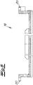
- This is inventively designed as a longitudinally divided shell and has several, in the exemplary embodiment four, shell segments 19. Consequently, this stator jacket 3 forms, with its jacket segments 19, a stator clamping device or stator adjusting device with which the longitudinally divided stator 1 can be fixed and sealed on the one hand and a desired voltage or bias voltage can be introduced into the stator 1 on the other hand.
- This succeeds within the scope of the invention in a particularly uniform manner, since four or more shell segments 19 are used. In Fig. 1 only one of these shell segments is shown.
- the outer side of the stator 1 adjacent jacket segments 19 have end mounting flanges 20 for attaching the shell segments 19 to the adapter pieces 11, 12. These mounting flanges 20 engage over the adapter piece 11, 12.
- the mounting flanges 20 are connected to the shell segment 19 by means of welded joints.
- the shroud segments 20 can also be made in one piece, including mounting flange.
- a plurality of stud bolts are connected as screw bolts 22 to the connecting flanges 9, 10 or in the exemplary embodiment adapter pieces 11, 12.
- the desired voltages can be adjusted via suitable nuts 23.
- the end attachment flanges thus have openings for the studs 22 or suitable screws on.
- the figures show that the attachment takes place with an adjustable annular gap R between the mounting flanges of the shell segments 19 and the adapter pieces. By adjusting this annular gap R, the desired preload can then be adjusted or re-tensioned.
- the shell segments 19 can then be fixed by means of screw 24 in the longitudinal direction of the adapter pieces or flanges.
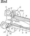
- stator partial shells 1 a, 1 b each have at least one torsion protection 25 projecting on the outside, which in the exemplary embodiment are designed as longitudinal webs 25 extending over almost the entire stator length, which are integrally formed on the outside of the stator, for example vulcanized.
- Fig. 6 shows that these longitudinal webs 25 engage in the course of assembly in intermediate spaces between the individual maneseat segments 19, so that the longitudinal webs are as it were clamped between two adjacent shell segments 19 and thus form an anti-rotation.
- the longitudinal webs 25 but also the axial securing, because they are placed in their length to the distance between the adapter pieces, so that stops 26 are provided, which rest against the adapter pieces 11, 12.
- the longitudinally divided stator 1 according to the invention is preferably first manufactured as a one-piece stator 1 and then separated, for example in the way of water jet cutting. This allows a simple and cost-effective production.
- Fig. 1 to 7 show a possible embodiment in which stator 1 is inserted into corresponding receptacles 15, 16. This ensures a good seal in the course of clamping.
- Fig. 8 to 10 show embodiments, in which the stator 1 with its partial shells 1 a, 1 b on suitable "projecting" receptacles 15 ', 16' can be plugged.
- Fig. 8 shows a preferred embodiment of the invention, which in its basic structure of the embodiment according to Fig. 1 to 7 equivalent. It differs from this embodiment essentially in that the stator 1 is not inserted with its ends in a receptacle, but on recordings 15 ', 16' is attached.
- the stator 1 therefore has end-side sealing surfaces 13 ', 14', which are formed inside-conical.
- the Statorfactn 15 ', 16' have accordingly outer-conical sealing mating surfaces 17 ', 18'.
- the Statorfactn 15 ', 16' are therefore each formed by a projecting axially outwardly sealing collar, which is formed in the embodiment of the adapter piece.
- stator receivers 15 ', 16' engage, as it were, in the interior of the stator end of the stator 1.
- Fig. 8 Strictly shows only the one end of the arrangement with the reference numerals 13 ', 15' and 17 '.
- the reference numerals 14 ', 16' and 18 ', which refer to the opposite, not shown end, are therefore provided in parentheses for the sake of completeness.
- the stator 1 is also formed in several parts in this embodiment. In detail, the structure - apart from the configuration of the stator receptacles and the sealing surfaces - the structure according to Fig. 1 to 7 ,
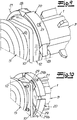
- Fig. 8 recognizable that means for receiving Kipp beyond or radial forces can be provided on the connecting flanges and / or adapter pieces.
- Fig. 8 Radially projecting from the adapter pieces threaded pins 27 can be seen, which engage in corresponding recesses on the stator casing or on the mounting flanges 20.
- These setscrews 27 are thus provided in addition to the clamping means 21 provided anyway. While on the clamping means 21, the adjustment the segments can take place, the set screws 27 serve to receive the tilting forces or radial forces.
- Fig. 9 shows an example of an alternative way to accommodate the tilting forces or radial forces.
- the in Fig. 8 Grub screws 27 omitted.
- spacers are used between the individual shell segments or their mounting flanges, which are wedge-shaped in the embodiment as guide wedges 28.
- FIG. 10 Another way to absorb tilting forces or radial forces.
- a quasi-positive connection between the connecting flanges or adapter pieces on the one hand and the shell segments or their mounting flanges on the other hand is provided.
- claw-like projections 29 are provided, which engage in corresponding receptacles or recesses 29b on the respective shell segment or its mounting flange.
- axial and radial securing via these form-locking elements, eg, claws, on the centering ring on the one hand and the stator adjustment segment on the other hand are possible.
Landscapes
- Engineering & Computer Science (AREA)
- Mechanical Engineering (AREA)
- General Engineering & Computer Science (AREA)
- Rotary Pumps (AREA)
- Details And Applications Of Rotary Liquid Pumps (AREA)
Abstract
Description
- Die Erfindung betrifft eine Exzenterschneckenpumpe mit zumindest einem Stator aus einem elastischen Material und einem in dem Stator gelagerten Rotor, wobei der Stator zumindest bereichsweise von einem Statormantel bzw. Statorgehäuse umgeben ist. - Bei einer solchen Exzenterschneckenpumpe ist der Rotor regelmäßig über zumindest eine Kupplungsstange, welche auch als Gelenkwelle bezeichnet wird, mit dem Antrieb bzw. der Antriebswelle verbunden. Die Pumpe weist ein Sauggehäuse sowie einen Anschlussstutzen auf, wobei der Stator mit seinem einen Ende an einen Anschlussflansch des Sauggehäuses und seinem anderen Ende an einen Anschlussflansch des Anschlussstutzens angeschlossen ist. Elastisches Material meint im Rahmen der Erfindung insbesondere einen Elastomer, z.B. einen (Synthese-)Kautschuk oder eine Kautschukmischung. Es werden im Übrigen auch Verbundwerkstoffe aus einem Elastomer oder einem anderen Material, z.B. Metall, umfasst.
- Aus der Praxis sind Exzenterschneckenpumpen bekannt, bei welchen der elastische Stator in einen Statormantel aus z.B. Metall einvulkanisiert ist. Die elastomeren Statoren unterliegen während des Betriebes einem Verschleiß, so dass in regelmäßigen Abständen Wartungsarbeiten bzw. ein Stator-Austausch erforderlich ist. In der Praxis werden dazu häufig die Statoren mit ihren angeformten Statormänteln ausgetauscht.
- Aus Kostengründen und auch aus Gründen des Umweltschutzes wurde daher in der Praxis vorgeschlagen, den elastomeren Stator einerseits und den Statormantel bzw. Statorgehäuse aus Metall andererseits als separate Bauteile zu fertigen. Der Stator kann dann im Zuge der Montage in den zylindrischen Statormantel aus Metall eingeschoben werden, so dass nach entsprechendem Verschleiß lediglich der Stator ausgetauscht und der Statormantel wieder verwendet werden kann. Derartige Statoren werden auch als Einschubstator bezeichnet. Die Montage eines derartigen Einschubstators ist jedoch in der Praxis häufig aufwendig und mit einer umfangreichen Zerlegung der Exzenterschneckenpumpe verbunden.
- Außerdem kennt man aus der
DE 28 17 280 , welche als nächtstliegendes Stand der Technik zu betrachten ist, eine Exzenterschneckenpumpe mit einem Stator aus einem elastischen Material und einem in dem Stator gelagerten Rotor, wobei der Stator zumindest bereichsweise von einem Statormantel umgeben ist. Um die Betriebskosten durch Verschleiß des Stators bzw. Statorfutters möglichst gering zu halten, wird dort vorgeschlagen, das Futter bzw. den Stator als auswechselbares, selbstständiges Bauteil auszubilden, so dass nach entsprechendem Verschleiß lediglich der elastomere Stator und nicht der ganze Stator mit Statormantel auszuwechseln sind. Der elastomere Stator ist einstückig ausgebildet. - Aus der
DE 19 95 352 ist eine Exzenterschneckenpumpe mit einer Zweiteilung von Stator und Statormantel in Längsrichtung bekannt. Durch eine solche wird eine vereinfachte Montage bzw. Demontage und Reparatur erreicht. - Der Erfindung liegt die Aufgabe zugrunde, eine Exzenterschneckenpumpe der eingangs beschriebenen Art zu schaffen, welche einen Austausch des elastischen Stators auf kostengünstige und montagetechnisch einfache Weise ermöglicht.
- Zur Lösung dieser Aufgabe lehrt die Erfindung eine Exzenterschneckenpumpe mit den Merkmalen des Anspruchs 1. Der Stator besteht als längsgeteilter Stator aus zumindest zwei Stator-Teilschalen. Es handelt sich vorzugsweise um zwei Stator-Teilschalen, die folglich als Halbschalen ausgeführt sind und jeweils einen Winkel von 180° überdecken. Die Erfindung umfasst jedoch auch geteilte Statoren mit drei, vier oder auch mehr Teilschalen, die dann jeweils einen Winkel von 120° bzw. 90° oder auch weniger überdecken.
- Dabei geht die Erfindung zunächst einmal von der Erkenntnis aus, dass es zweckmäßig ist, den elastomeren Stator als von dem Statormantel bzw. Statorgehäuse separat austauschbares Bauteil herzustellen, um einen Austausch lediglich des elastomeren Bauteils und eine Wiederverwertbarkeit des Statormantels zu gewährleisten. Im Rahmen der Erfindung wird darüber hinaus jedoch eine besonders einfache Montage erreicht, denn durch die längsgeteilte Bauweise des elastomeren Stators kann der Austausch erfolgen, ohne dass eine aufwendige Zerlegung der Pumpe notwendig ist. Die Pumpe kann in ihrem grundsätzlichen Aufbau auf z.B. einer Grundplatte bzw. Montageplatte montiert bleiben. Sauggehäuse einerseits und Anschlussstutzen andererseits sowie der Rotor können montiert bleiben. Die beiden Halbschalen bzw. die mehreren Teilschalen können dann gleichsam um den Rotor herum montiert werden. Dazu wird der Stator mit seinen Enden einerseits an einen Anschlussflansch des Sauggehäuses und andererseits an einen Anschlussflansch des Anschlussstutzens angeschlossen, wobei die separaten Teilschalen - wie erläutert - einzeln montiert werden können, ohne dass eine Demontage der Pumpe erforderlich ist. Dieses gelingt auch deshalb, weil die Teilschalen elastisch verformbar sind und daher zum Einsetzen knickbar bzw. biegbar sind. Es kann zweckmäßig sein, den Stator bzw. die Stator-Teilschalen nicht unmittelbar an den Anschlussflanschen zu montieren, sondern Adapterstücke vorzusehen, welche an den oder die Anschlussflansche angeschlossen sind. Diese z.B. ringförmigen Adapterstücke sind an die Geometrie des Stators bzw. die Stator-Teilschalen angepasst, so dass mit Hilfe der Adapterstücke grundsätzlich auch die Möglichkeit besteht, den erfindungsgemäßen längsgeteilten Stator im Zusammenhang mit herkömmlichen Pumpengehäusen bzw. Sauggehäusen und Anschlussstutzen zu verwenden. Die Adapterstücke können auch als Zentrierringe bezeichnet werden.
- Die Erfindung sieht vor, dass der Stator bzw. die Stator-Teilschalen mit endseitigen Dichtungsflächen jeweils in eine Statoraufnahme des entsprechenden Anschlussflansches bzw. des entsprechenden Adapterstückes einsteckbar oder auf eine solche aufsteckbar sind. Durch dieses Einstecken der Statorenden in geeignete Statoraufnahmen oder ein Aufstecken auf geeignete vorkragende Statoraufnahmen wird insbesondere im Zuge des Montierens des Statorgehäuses eine einwandfreie Dichtigkeit gewährleistet, da im Zuge der Montage des Statorgehäuses bzw. Statormantels die endseitigen Dichtungsflächen in die Dichtungsaufnahmen eingreifen oder (umgekehrt) die vorkragenden Statoraufnahmen in die Dichtflächen des Stators eingreifen.
- Dabei weist der Stator endseitig konische, vorzugsweise außen-konische oder innen-konische Dichtungsflächen auf, während die beschriebenen Statoraufnahmen der Anschlussflansche bzw. Adapterstücke konische, vorzugsweise innen-konische bzw. außen-konische Dichtungsgegenflächen aufweisen. In einer ersten Ausführungsform sind die endseitigen Dichtungs-flächen des Stators auβen konisch ausgebildet und diese liegen dann gegen die innen-konischen Dichtungsgegenflächen der Statoraufnahme an. In einer abgewandelten, bevorzugten Ausführungsform weist der Stator endseitig innen-konische Dichtungsflächen auf und die Statoraufnahmen am Anschlussflansch oder am Adapterstück weisen außen-konische Dichtungsgegenflächen auf. Bei dieser Ausführungsform kragt die Statoraufnahme gleichsam in axialer bzw. achsparalleler Richtung aus dem Anschlussflansch bzw. dem Adapterstück vor, so dass die Statoraufnahme in das Statorende eingreift bzw. der Stator auf die Statoraufnahme aufgesteckt wird. Auf diese Weise lässt sich eine besonders gute Dichtigkeit erzeugen. Insgesamt wird durch die Konizität bzw. kegelförmige Ausgestaltung eine hervorragende Dichtigkeit gewährleistet. Der Konuswinkel der Dichtungsflächen bzw. der Dichtungsgegenflächen kann 10° bis 50°, vorzugsweise 20° bis 30° betragen.
- Erfindungsgemäß ist nicht nur der Stator selbst als längsgeteilter Stator ausgebildet, sondern auch der Statormantel ist als längsgeteilter Mantel ausgebildet und weist dazu zumindest zwei, vorzugsweise zumindest vier Mantelsegmente auf. Auch dieses trägt dazu bei, dass der ein Verschleißteil bildende elastomere Stator ohne größere Demontage ausgetauscht werden kann, denn auch der mehrteilige Statormantel lässt sich nun demontieren, ohne dass Sauggehäuse, Druckstutzen und/oder Rotor aus ihrer Einbauposition entfernt werden müssen. Darüber hinaus bildet ein solcher längsgeteilter Statormantel mit seinen mehreren Mantelsegmenten zugleich eine Stator-Spannvorrichtung bzw. Stator-Einstellvorrichtung, mit welcher der Stator insbesondere in radialer Richtung gegen den Rotor spannbar ist. Dabei geht die Erfindung von der Erkenntnis aus, dass der elastomere Stator gegenüber dem drehbar angetriebenen Rotor üblicherweise mit einer Vorspannung montiert wird, wobei die Funktion der Exzenterschneckenpumpe wesentlich von dieser Vorspannung abhängt. Trotz des einfachen Aufbaus und insbesondere des einfachen Austausches des Stators lässt sich nun das gewünschte Vorspannmaß hervorragend einstellen und insbesondere auch eine Nachspannung bei entsprechendem Verschleiß einrichten. Zugleich wird über die mehrteilige Spannvorrichtung die Dichtheit des längsgeteilten Stators gewährleistet. Dabei gewährleistet die Stator-Spannvorrichtung nicht nur eine ausreichende Dichtheit bzw. Verbindung der beiden Stator-Teilschalen zueinander, sondern auch eine dichte Verbindung bzw. ein dichtes Eingreifen der Statorenden in die entsprechenden Stator-Aufnahmen der Anschlussflansche bzw. Adapterstücke.
- In diesem Zusammenhang schlägt die Erfindung vor, dass die außenseitig gegen den Stator anliegenden Mantelsegmente z.B. endseitig Befestigungsflansche für die Befestigung an dem Anschlussflansch oder Adapterstück aufweisen. Diese Befestigungsflansche können zum Zwecke des Spannens des Stators mit Spannmitteln an den Anschlussflansch bzw. das Adapterstück angeschlossen werden. Die Spannmittel können dabei als Schraubvorrichtungen ausgebildet sein, so dass auf einfache Weise die gewünschte Vorspannung eingestellt oder auch nachgestellt werden kann. Die Mantelsegmente sind mit ihren Befestigungsflanschen so an die Geometrie des Stators und der Anschlussflansche bzw. Adapterstücke angepasst, dass die Befestigung der Befestigungsflansche an den Anschlussflanschen bzw. Adapterstücken unter Bildung eines einstellbaren Ringspaltes erfolgt. Dieser kann eine Spaltweite von bis zu 10 mm, vorzugsweise bis zu 5 mm betragen. Es kann folglich zweckmäßig sein, die Befestigungsflansche zunächst mit einer Spaltweite von z.B. 5 mm zu montieren, so dass dann bei auftretendem Verschleiß eine Nachspannung von insgesamt 5 mm Spannweg erfolgen kann.
- Dabei können die Befestigungsflansche in den Anschlussflansch oder das Adapterstück übergreifen bzw. umgreifen. Dazu wird auf die Figuren und die Figurenbeschreibung verwiesen.
- Ferner schlägt die Erfindung in einer Weiterentwicklung vor, dass eine oder mehrere, vorzugsweise alle, Stator-Teilschalen jeweils zumindest eine außenseitig vorkragende Verdrehsicherung aufweisen. Eine solche Verdrehsicherung kann z.B. als Längssteg außenseitig an die Stator-Teilschalen angeschlossen sein. Die Geometrie der Stator-Teilschalen mit ihren Längsstegen ist dabei vorzugsweise an die Geometrie der mehreren Mantelsegmente angepasst, so dass im Rahmen der Erfindung die Längsstege unter Bildung der Verdrehsicherung in entsprechende Zwischenräume zwischen zwei benachbarten Mantelsegmenten eingreifen. Darüber hinaus können diese Stege auch endseitige Anschläge aufweisen, welche als Axialsicherung dienen und dazu gegen die Adapterstücke bzw. Anschlussflansche anliegen.
- Insgesamt lässt sich der erfindungsgemäße Stator einfach montieren und austauschen, ohne dass z.B. Druckstutzen oder Druckleitungen gelöst werden müssen. Die erforderliche Rotor-Stator-Klemmung lässt sich gut einstellen. Der Stator lässt sich bezogen auf die Statorgeometriemaße einfach herstellen, da keine exakte Maßgenauigkeit mehr erforderlich ist.
- Im Folgenden wird die Erfindung anhand einer lediglich ein Ausführungsbeispiel darstellenden Zeichnung näher erläutert. Es zeigen
- Fig. 1
- eine vereinfachten Längsschnitt durch eine erfindungsgemäße Exzenterschneckenpumpe,
- Fig. 2
- einen erfindungsgemäßen längsgeteilten Stator in einer Stirnansicht,
- Fig. 3
- einen Schnitt A-B durch den Gegenstand nach
Fig. 2 , - Fig. 4
- ein erfindungsgemäßes Adapterstück für den Gegenstand nach
Fig. 1 , - Fig. 5
- ein erfindungsgemäßes Mantelsegment für den Gegenstand nach
Fig. 1 in einem Längsschnitt, - Fig. 6
- einen Ausschnitt aus dem Gegenstand nach
Fig. 1 in perspektivischer Ansicht, - Fig. 7
- den Gegenstand nach
Fig. 6 in einer anderen Ansicht in teilweise demontiertem Zustand, - Fig. 8
- eine weitere Ausführungsform der Erfindung,
- Fig. 9
- eine abgewandelte Ausführungsform der Erfindung und
- Fig. 10
- eine andere Ausführungsform der Erfindung.
- In den Figuren ist eine Exzenterschneckenpumpe dargestellt, welche in ihrem grundsätzlichen Aufbau einen Stator 1 aus einem elastischen Material und einen in dem Stator 1 gelagerten Rotor 2 aufweist, wobei der Stator 1 zumindest bereichsweise von einem Statormantel 3 umgeben ist. Ferner weist die Pumpe ein Sauggehäuse 4 sowie einen Anschlussstutzen 5 auf, welcher auch als Druckstutzen bezeichnet wird. Nicht dargestellt ist ein ebenfalls vorgesehener Antrieb, wobei der Antrieb über eine lediglich angedeutete Kupplungsstange 6 auf den Rotor 2 arbeitet. Die Kupplungsstange ist über Kupplungsgelenke einerseits an den Rotor 2 und andererseits an die nicht dargestellte Antriebeswelle angeschlossen, wobei von den Kupplungsgelenken lediglich das rotorseitige Gelenk 7 dargestellt ist. Die Pumpe ist üblicherweise auf einer lediglich angedeuteten Grundplatte 8 montiert, wobei es sich insoweit um eine mit der Pumpe ausgelieferte Grundplatte oder auch eine anwenderseitig vorhandene Grundplatte handeln kann. Der Stator 1 ist in an sich bekannter Weise mit seinem einen Ende an einem Anschlussflansch 9 des Sauggehäuses 4 und mit seinem anderen Ende an einen Anschlussflansch 10 des Anschlussstutzens 5 angeschlossen. Dabei erfolgt der Anschluss bei dem dargestellten Ausführungsbeispiel nicht unmittelbar an diese Anschlussflansche 9, 10, sondern unter Zwischenschaltung jeweils eines Adapterstückes 11, 12, dessen Aufbau im Folgenden noch näher erläutert wird. Diese Adapterstücke werden auch als Zentrierringe bezeichnet.
- Erfindungsgemäß ist der Stator 1 nun als längsgeteilter Stator ausgebildet und besteht dazu aus zwei Stator-Teilschalen 1 a, 1 b, welche im Ausführungsbeispiel Halbschalen bilden, die jeweils einen Winkel von 180° überdecken. Längsgeteilt meint, entlang der Statorlängsachse L bzw. parallel zu dieser. Der Trennschnitt zwischen den Teilschalen verläuft folglich entlang bzw. parallel zu der Längsachse L.
- Diese längsgeteilte Ausgestaltung des elastomeren Stators ermöglicht es, den Stator 1 bei montiertem Sauggehäuse 4, Druckstutzen 5 und Rotor 2 zu demontieren und zu montieren, da der Stator 1 nicht - wie beim Stand der Technik - z.B. nach Entfernen des Druckstutzens 5 von einer Seite auf den Rotor 2 aufgeschoben werden muss.
- Um trotz dieser geteilten Bauweise eine ausreichende Dichtigkeit des Stators zu gewährleisten, weist der Stator 1 bzw. dessen Stator-Teilschalen 1 a, 1 b endseitig Dichtungsflächen 13, 14 (bzw. 13', 14') auf. Die Stator-Teilschalen 1a, 1 b sind dann (nacheinander) mit ihren endseitigen Dichtungsflächen 13, 14 in Statoraufnahmen 15, 16 einsteckbar oder mit Dichtungsflächen 13', 14' auf solche Statoraufnahmen 15', 16' aufsteckbar, wobei diese Statoraufnahmen bei dem hier dargestellten Ausführungsbeispiel mit Adapterstücken an diesen Adapterstücken 11, 12 vorgesehen sind. Die Adapterstücke 11, 12 selbst sind in an sich bekannte Aufnahmen von einerseits Sauggehäuse 4 und andererseits Druckstutzen 5 einsetzbar, so dass Sauggehäuse 4 einerseits und Druckstutzen 5 andererseits in herkömmlicher Bauweise ausgebildet sein können und folglich auch mit herkömmlichen einteiligen Statoren verwendet werden können. Die endseitigen Dichtungsflächen 13, 14 (bzw. 13', 14') des Stators 1 sind konisch bzw. als Kegelmantelflächen ausgebildet, und zwar bei der Ausführungsform nach
Fig. 1 bis 7 "außen-konisch". Die Statoraufnahmen 15, 16 (bzw. 15', 16') weisen ebenfalls korrespondierende konische Dichtungsgegenflächen 17, 18 (17', 18') auf, die gemäßFig. 1 bis 7 innen-konisch ausgebildet sein können. Der inFig. 1 dargestellte Konuswinkel α relativ zur Längsachse L beträgt dabei im Ausführungsbeispiel etwa 25°. Die Abdichtung erfolgt durch Gummiquetschung. Um die Stator-Teilschalen 1 a, 1 b zu fixieren und abzudichten, ist der Statormantel 3 vorgesehen. Dieser ist erfindungsgemäß als längsgeteilter Mantel ausgebildet und weist dazu mehrere, im Ausführungsbeispiel vier, Mantelsegmente 19 auf. Dieser Statormantel 3 bildet mit seinen Mantelsegmenten 19 folglich eine Statorspannvorrichtung bzw. Statoreinstellvorrichtung, mit welcher sich einerseits der längsgeteilte Stator 1 fixieren und abdichten lässt und andererseits eine gewünschte Spannung bzw. Vorspannung in den Stator 1 einbringen lässt. Dieses gelingt im Rahmen der Erfindung in besonders gleichmäßiger Weise, da mit vier oder auch mehr Mantelsegmenten 19 gearbeitet wird. InFig. 1 ist lediglich eines dieser Mantelsegmente dargestellt. - Die außenseitig an den Stator 1 anliegende Mantelsegmente 19 weisen endseitig Befestigungsflansche 20 für die Befestigung der Mantelsegmente 19 an den Adapterstücken 11, 12 auf. Diese Befestigungsflansche 20 übergreifen das Adapterstück 11, 12. In
Fig. 5 ist erkennbar, dass die Befestigungsflansche 20 mittels Schweißverbindungen an das Mantelsegment 19 angeschlossen sind. Die Mantelsegmente 20 können jedoch auch jeweils einstückig, einschließlich Befestigungsflansch, gefertigt sein. Zum Zwecke des Spannens des Stators 1 weisen die Befestigungsflansche 20 Spannmittel 21 auf, welche im Ausführungsbeispiel als Schraubverbindungen 22, 23 ausgebildet sind. Dazu ist in den Figuren erkennbar, dass an die Anschlussflansche 9, 10 oder im Ausführungsbeispiel Adapterstücke 11, 12 mehrere Stehbolzen als Schraubenbolzen 22 angeschlossen sind. Nach Aufsetzen der Mantelsegmente 19 mit ihren Befestigungsflanschen 20 können dann über geeignete Muttern 23 die gewünschten Spannungen eingestellt werden. Die endseitigen Befestigungsflansche weisen folglich Durchbrechungen für die Stehbolzen 22 oder geeignete Schrauben auf. Dabei zeigen die Figuren, dass die Befestigung mit einem einstellbaren Ringspalt R zwischen den Befestigungsflanschen der Mantelsegmente 19 und den Adapterstücken erfolgt. Durch Einstellen dieses Ringspaltes R kann dann die gewünschte Vorspannung eingestellt werden bzw. nachgespannt werden. Im Übrigen lassen sich die Mantelsegmente 19 dann mittels Schraubverbindungen 24 in Längsrichtung an den Adapterstücken oder Flanschen fixieren. - Ferner weisen die Stator-Teilschalen 1a, 1 b jeweils zumindest eine außenseitig vorkragende Verdrehsicherung 25 auf, welche im Ausführungsbeispiel als sich über nahezu die gesamte Statorlänge erstreckende Längs-Stege 25 ausgebildet sind, welche außenseitig an den Stator angeformt, z.B. anvulkanisiert sind. Insbesondere
Fig. 6 zeigt, dass diese Längs-Stege 25 im Zuge der Montage in Zwischenräume zwischen den einzelnen Mantensegmenten 19 eingreifen, so dass die Längsstege gleichsam zwischen zwei benachbarten Mantelsegmenten 19 festgeklemmt werden und insoweit eine Verdrehsicherung bilden. Darüber hinaus dienen die Längs-Stege 25 aber auch der Axialsicherung, denn sie sind in ihrer Länge auf den Abstand zwischen den Adapterstücken abgestellt, so dass Anschläge 26 vorgesehen sind, welche gegen die Adapterstücke 11, 12 anliegen. - Im Zuge der Fertigung wird der erfindungsgemäße längsgeteilte Stator 1 vorzugsweise zunächst als einteiliger Stator 1 gefertigt und anschließend aufgetrennt, z.B. im Wege des Wasserstrahlschneidens. Dieses ermöglicht eine einfache und kostengünstige Fertigung.
- Die
Fig. 1 bis 7 zeigen eine mögliche Ausführungsform, bei welcher Stator 1 in entsprechende Aufnahmen 15, 16 eingesteckt wird. Dieses gewährleistet eine gute Abdichtung im Zuge des Spannens.Fig. 8 bis 10 zeigen Ausführungsformen, bei denen der Stator 1 mit seinen Teilschalen 1 a, 1 b auf geeignete "vorkragende" Aufnahmen 15', 16' aufsteckbar ist. -
Fig. 8 zeigt eine bevorzugte Ausführungsform der Erfindung, welche in ihrem grundsätzlichen Aufbau der Ausführungsform nachFig. 1 bis 7 entspricht. Sie unterscheidet sich von dieser Ausführungsform im Wesentlichen dadurch, dass der Stator 1 mit seinen Enden nicht in eine Aufnahme eingesteckt, sondern auf Aufnahmen 15', 16' aufgesteckt wird. Der Stator 1 weist folglich endseitige Dichtungsflächen 13', 14' auf, welche innen-konisch ausgebildet sind. Die Statoraufnahmen 15', 16' weisen dementsprechend außen-konische Dichtungsgegenflächen 17', 18' auf. Die Statoraufnahmen 15', 16' werden folglich jeweils von einem in axialer Richtung nach außen vorkragenden Dichtungsbund gebildet, welcher im Ausführungsbeispiel an das Adapterstück angeformt ist. Insofern greifen diese Statoraufnahmen 15', 16' gleichsam in das Innere des Statorendes des Stators 1 ein.Fig. 8 zeigt in Strenge lediglich das eine Ende der Anordnung mit den Bezugsziffern 13', 15' und 17'. Die Bezugsziffern 14', 16' und 18', welche sich auf das gegenüberliegende, nicht dargestellte Ende beziehen, sind daher der Vollständigkeit halber in Klammern vorgesehen. Der Stator 1 ist im Übrigen auch bei dieser Ausführungsform mehrteilig ausgebildet. Im Einzelnen entspricht der Aufbau - abgesehen von der Ausgestaltung der Stator-aufnahmen und der Dichtungsflächen - dem Aufbau gemäßFig. 1 bis 7 . - Ergänzend ist in
Fig. 8 erkennbar, dass an den Anschlussflanschen und/oder Adapterstücken Mittel zur Aufnahme von Kippkräften bzw. Radialkräften vorgesehen sein können. Dazu sind inFig. 8 radial aus den Adapterstücken vorkragende Gewindestifte 27 erkennbar, welche in korrespondierende Ausnehmungen am Statormantel bzw. an dessen Befestigungsflanschen 20 eingreifen. Diese Gewindestifte 27 sind folglich ergänzend zu den ohnehin vorgesehenen Spannmitteln 21 vorgesehen. Während über die Spannmittel 21 die Nachstellung der Segmente erfolgen kann, dienen die Gewindestifte 27 der Aufnahme der Kippkräfte bzw. Radialkräfte. -
Fig. 9 zeigt beispielhaft eine alternative Möglichkeit zur Aufnahme der Kippkräfte bzw. Radialkräfte. Bei dieser Ausführungsform wird auf die inFig. 8 dargestellten Gewindestifte 27 verzichtet. Stattdessen sind zwischen den einzelnen Mantelsegmenten bzw. deren Befestigungsflanschen Distanzelemente eingesetzt, die im Ausführungsbeispiel keilförmig als Führungskeile 28 ausgebildet sind. - Schließlich zeigt
Fig. 10 eine weitere Möglichkeit, Kippkräfte bzw. Radialkräfte aufzunehmen. Dazu ist eine gleichsam formschlüssige Verbindung zwischen den Anschlussflanschen oder Adapterstücken einerseits und den Mantelsegmenten bzw. deren Befestigungsflanschen andererseits vorgesehen. In dem Ausführungsbeispiel nachFig. 10 sind klauenartige Vorsprünge 29 vorgesehen, welche in korrespondierende Aufnahmen bzw. Ausnehmungen 29b an dem jeweiligen Mantelsegment bzw. dessen Befestigungsflansch eingreifen. Auf diese Weise gelingt eine axiale und radiale Sicherung über diese Formschlusselemente, z.B. Klauen, an dem Zentrierring einerseits und dem Stator-Einstellsegment andererseits.
Claims (11)
- Exzenterschneckenpumpe mit zumindest einem Stator (1) aus einem elastischen Material und einem in dem Stator (1) gelagerten Rotor (2),
mit einem Sauggehäuse (4) und einem Anschlussstutzen (5), wobei der Stator mit seinem einen Ende an einen Anschlussflansch (9) des Sauggehäuses (4) und mit seinem anderen Ende an einen Anschlussflansch (10) des Anschlussstutzens angeschlossen ist,
wobei der Stator (1) zumindest bereichsweise von einem Statormantel (3) umgeben ist,
wobei der Stator (1) als längsgeteilter Stator aus zumindest zwei Stator-Teilschalen (1, 1 b) besteht,
wobei der Stator (1) bzw. die Stator-Teilschalen (1a, 1b) mit endseitigen Dichtungsflächen (13, 14, 13', 14') in jeweils eine Statoraufnahme (15, 16, 15', 16') des Anschlussflansches (9, 10) oder eines Adapterstückes (11, 12) einsteckbar oder auf eine solche aufsteckbar ist,
wobei der Stator (1) endseitig konische, z.B. außen-konische oder innen-konische Dichtungsflächen (13, 14, 13', 14') aufweist,
wobei die Statoraufnahmen (15, 16, 15', 16') der Anschlussflansche oder Adapterstücke konische, z.B. innen-konische oder außen-konische Dichtungsgegenflächen (17, 18, 17', 18') aufweisen,
wobei der Statormantel (3) als längsgeteilter Mantel ausgebildet ist und zumindest zwei, vorzugsweise vier Mantelsegmente (19) aufweist, und
wobei der Statormantel (3) mit seinen Mantelsegmenten (19) eine Stator-Spannvorrichtung bildet, mit welcher der Stator (1) in radialer Richtung gegen den Rotor (2) spannbar ist. - Exzenterschneckenpumpe nach Anspruch 1, dadurch gekennzeichnet, dass der Stator (1) bzw. die Teilschalen (1 a, 1 b) unter Zwischenschaltung eines oder mehrerer Adapterstücke (11, 12) an den oder die Anschlussflansche (9, 10) angeschlossen ist.
- Exzenterschneckenpumpe nach Anspruch 1 oder 2, dadurch gekennzeichnet, dass der Konuswinkel (α) der Dichtungsflächen (13, 14) und/oder der Dichtungsgegenflächen (17, 18, 17', 18') etwa 10° bis 50°, vorzugsweise 20° bis 30° beträgt.
- Exzenterschneckenpumpe nach einem der Ansprüche 1 bis 3, dadurch gekennzeichnet, dass die außenseitig gegen den Stator (1) anliegenden Mantelsegmente (19) z.B. endseitig Befestigungsflansche (20) für die Befestigung an dem Anschlussflansch (9, 10) bzw. dem Adapterstück (11, 12) aufweisen.
- Exzenterschneckenpumpe nach Anspruch 4, dadurch gekennzeichnet, dass die Befestigungsflansche (20) zum Zwecke des Spannens des Stators mit Spannmitteln (21) an den Anschlussflansch (9, 10) oder das Adapterstück (11, 12) angeschlossen sind.
- Exzenterschneckenpumpe nach Anspruch 5, dadurch gekennzeichnet, dass die Spannmittel (21) als Spannschraubvorrichtungen (22, 23) ausgebildet sind.
- Exzenterschneckenpumpe nach einem der Anspruch 4 bis 6, dadurch gekennzeichnet, dass die Befestigungsflansche mit einstellbarem Ringspalt (R) an den Anschlussflansch (9, 10) oder das Adapterstück (11, 12) angeschlossen sind.
- Exzenterschneckenpumpe nach einem der Ansprüche 4 bis 7, dadurch gekennzeichnet, dass die Befestigungsflansche (20) den Anschlussflansch (9, 10) oder das Adapterstück (11, 12) übergreifen oder umgreifen.
- Exzenterschneckenpumpe nach einem der Ansprüche 1 bis 8, dadurch gekennzeichnet, dass eine oder mehrere, vorzugsweise alle, Stator-Teilschalen (1 a, 1 b) jeweils zumindest eine außenseitig vorkragende Verdrehsicherung (25) aufweisen.
- Exzenterschneckenpumpe nach Anspruch 9, dadurch gekennzeichnet, dass die Verdrehsicherung (25) als außenseitig an die Stator-Teilschale angeschlossener, z.B. angeformter, Längs-Steg (25) ausgebildet ist.
- Exzenterschneckenpumpe nach Anspruch 10, dadurch gekennzeichnet, dass der Längs-Steg (25) endseitige Anschläge (26) als Axialsicherung aufweist.
Priority Applications (1)
| Application Number | Priority Date | Filing Date | Title |
|---|---|---|---|
| PL08785517T PL2176552T3 (pl) | 2007-08-17 | 2008-08-13 | Mimośrodowa pompa śrubowa z dzielonym statorem |
Applications Claiming Priority (4)
| Application Number | Priority Date | Filing Date | Title |
|---|---|---|---|
| DE102007039062 | 2007-08-17 | ||
| DE102008011690 | 2008-02-28 | ||
| DE102008021920A DE102008021920A1 (de) | 2007-08-17 | 2008-05-02 | Exzenterschneckenpumpe |
| PCT/EP2008/006641 WO2009024279A1 (de) | 2007-08-17 | 2008-08-13 | Exzenterschneckenpumpe mit geteiltem stator |
Publications (2)
| Publication Number | Publication Date |
|---|---|
| EP2176552A1 EP2176552A1 (de) | 2010-04-21 |
| EP2176552B1 true EP2176552B1 (de) | 2012-05-16 |
Family
ID=39942685
Family Applications (1)
| Application Number | Title | Priority Date | Filing Date |
|---|---|---|---|
| EP08785517A Active EP2176552B1 (de) | 2007-08-17 | 2008-08-13 | Exzenterschneckenpumpe mit geteiltem stator |
Country Status (8)
| Country | Link |
|---|---|
| US (1) | US8439659B2 (de) |
| EP (1) | EP2176552B1 (de) |
| JP (1) | JP2010537095A (de) |
| CN (1) | CN101796301B (de) |
| BR (1) | BRPI0815403A2 (de) |
| ES (1) | ES2387834T3 (de) |
| PL (1) | PL2176552T3 (de) |
| WO (1) | WO2009024279A1 (de) |
Cited By (1)
| Publication number | Priority date | Publication date | Assignee | Title |
|---|---|---|---|---|
| US12152588B1 (en) | 2023-05-26 | 2024-11-26 | Grant Prideco, Inc. | Free-mold stator for a progressing cavity pump |
Families Citing this family (37)
| Publication number | Priority date | Publication date | Assignee | Title |
|---|---|---|---|---|
| US8182252B2 (en) | 2007-10-30 | 2012-05-22 | Moyno, Inc. | Progressing cavity pump with split stator |
| US8215014B2 (en) | 2007-10-31 | 2012-07-10 | Moyno, Inc. | Method for making a stator |
| FR2948424B1 (fr) * | 2009-07-23 | 2017-07-21 | Pcm | Pompe a cavites progressives et dispositif de pompage associe |
| CN101892982B (zh) * | 2010-06-28 | 2012-06-20 | 中国石油大学(北京) | 单螺杆金属螺杆泵定子及其内螺旋面加工方法 |
| CN102725530B (zh) * | 2010-08-25 | 2015-08-19 | 古河产机系统株式会社 | 单轴偏心螺杆泵中的定子密封结构 |
| DE102010037440B4 (de) * | 2010-09-09 | 2014-11-27 | Seepex Gmbh | Exzenterschneckenpumpe |
| CN102062089A (zh) * | 2010-12-24 | 2011-05-18 | 新疆华易石油工程技术有限公司 | 一种全金属螺杆泵定子的加工方法 |
| DE102012112044B4 (de) * | 2012-05-04 | 2015-10-08 | Netzsch Pumpen & Systeme Gmbh | Selbstfixierendes Statorgehäuse |
| US8967985B2 (en) | 2012-11-13 | 2015-03-03 | Roper Pump Company | Metal disk stacked stator with circular rigid support rings |
| JP6318454B2 (ja) * | 2013-10-29 | 2018-05-09 | 兵神装備株式会社 | 一軸偏心ネジポンプ |
| JP6349566B2 (ja) * | 2014-01-28 | 2018-07-04 | 兵神装備株式会社 | 一軸偏心ネジポンプ |
| JP6349565B2 (ja) * | 2014-01-28 | 2018-07-04 | 兵神装備株式会社 | 一軸偏心ネジポンプ |
| DE102014112552B4 (de) | 2014-09-01 | 2016-06-30 | Seepex Gmbh | Exzenterschneckenpumpe |
| DE102014112550B4 (de) * | 2014-09-01 | 2016-06-16 | Seepex Gmbh | Exzenterschneckenpumpe |
| DE102015112248A1 (de) * | 2015-01-29 | 2016-08-04 | Netzsch Pumpen & Systeme Gmbh | Exzenterschneckenpumpe und Verfahren zum Anpassen des Betriebszustands einer Exzenterschneckenpumpe |
| CN105351184A (zh) * | 2015-11-23 | 2016-02-24 | 重庆高研泵业有限公司 | 安全螺杆泵 |
| CZ306826B6 (cs) * | 2016-04-01 | 2017-07-26 | Petr Havránek | Zařízení pro čerpání kapalin a výměnný dílec pro něj |
| DE102017100540B4 (de) | 2017-01-12 | 2018-09-06 | Seepex Gmbh | Exzenterschneckenpumpe |
| EP3382203B1 (de) * | 2017-03-30 | 2024-05-15 | Roper Pump Company LLC | Exzenterschneckenpumpe mit integriertem heizmantel |
| PL3473856T3 (pl) * | 2017-10-20 | 2021-07-26 | Circor Pumps North America, Llc. | Urządzenia do demontażu dla śrubowych pomp wyporowych |
| DE102018102640A1 (de) | 2018-02-06 | 2019-08-08 | Seepex Gmbh | Exzenterschneckenpumpe |
| DE202018101651U1 (de) * | 2018-03-16 | 2018-04-09 | Seepex Gmbh | Anlage zur Förderung von pastösem Material |
| DE102018113347A1 (de) | 2018-06-05 | 2019-12-05 | Seepex Gmbh | Verfahren zur Bestimmung oder Überwachung des Zustandes einer Exzenterschneckenpumpe |
| CN110410316B (zh) * | 2019-09-05 | 2024-06-11 | 无锡恒信北石科技有限公司 | 高稳定的全金属锥形螺杆泵的新型驱动提升装置 |
| JP6824537B1 (ja) * | 2019-09-24 | 2021-02-03 | 兵神装備株式会社 | 一軸偏心ねじポンプ |
| DE102019130981A1 (de) | 2019-11-15 | 2021-05-20 | Seepex Gmbh | Exzenterschneckenpumpe |
| EP3825552B1 (de) * | 2019-11-22 | 2025-03-12 | Grundfos Holding A/S | Exzenterschneckenpumpe |
| DE102021112422A1 (de) | 2021-05-12 | 2022-11-17 | Seepex Gmbh | Pumpe zum Fördern eines Mediums und Verfahren zur Überwachung |
| DE102021112419A1 (de) | 2021-05-12 | 2022-11-17 | Ruhr-Universität Bochum, Körperschaft des öffentlichen Rechts | Pumpe zum Fördern eines Mediums und Verfahren zur Überwachung |
| DE102021132561A1 (de) | 2021-12-09 | 2023-06-15 | Seepex Gmbh | Gelenkverbindung, rotierende Einheit und Exzenterschneckenpumpe |
| DE102021132549A1 (de) | 2021-12-09 | 2023-06-15 | Seepex Gmbh | Gelenkverbindung, rotierende Einheit und Exzenterschneckenpumpe |
| DE102022118485B3 (de) * | 2022-07-25 | 2023-12-21 | Netzsch Pumpen & Systeme Gmbh | System zum Verspannen eines Tauchrohrs einer Tankpumpe in einem Endstutzen |
| DE102022119147A1 (de) | 2022-07-29 | 2024-02-01 | Ruhr-Universität Bochum, Körperschaft des öffentlichen Rechts | Verfahren zur Bestimmung oder Überwachung des Förderstroms einer Exzenterschneckenpumpe |
| DE102022134734A1 (de) | 2022-12-23 | 2024-07-04 | Ruhr-Universität Bochum, Körperschaft des öffentlichen Rechts | Verfahren zur Steuerung einer Exzenterschneckenpumpe |
| WO2024249197A1 (en) * | 2023-05-26 | 2024-12-05 | Grant Prideco, Inc. | Progressive cavity pump |
| FR3153383A1 (fr) * | 2023-09-22 | 2025-03-28 | Pcm Technologies | Dispositif de pompage |
| FR3164507A1 (fr) | 2024-07-09 | 2026-01-16 | Pcm Technologies | Chemisage de stator, stator, et procédé de fabrication d’un chemisage de stator |
Citations (3)
| Publication number | Priority date | Publication date | Assignee | Title |
|---|---|---|---|---|
| DE1995352U (de) * | 1965-04-09 | 1968-10-24 | Oskar Seidl | Gehaeuse fuer exzenter-schraubspindelpumpen. |
| DE2754913A1 (de) * | 1977-12-09 | 1979-06-13 | Streicher Foerdertech | Exzenterscheibenpumpe |
| DE2817280A1 (de) * | 1978-04-20 | 1979-10-25 | Streicher Foerdertech | Stator fuer exzenterschneckenpumpen |
Family Cites Families (29)
| Publication number | Priority date | Publication date | Assignee | Title |
|---|---|---|---|---|
| FR1488652A (de) | 1967-10-25 | |||
| US2527670A (en) * | 1946-04-04 | 1950-10-31 | Robbins & Myers | Helical pump |
| US3354537A (en) * | 1965-12-01 | 1967-11-28 | Walter J O'connor | Renewable moineau-type pumping mechanism |
| US3512904A (en) * | 1968-05-24 | 1970-05-19 | Clifford H Allen | Progressing cavity helical pump |
| US3603407A (en) * | 1969-12-29 | 1971-09-07 | Wallace Clark | Well drilling apparatus |
| US3643877A (en) * | 1970-01-28 | 1972-02-22 | Robbins & Myers | Pump with macerator |
| DE2313261C3 (de) | 1973-03-16 | 1980-08-14 | Sumitomo Heavy Industries, Ltd., Tokio | Exzenterschneckenpumpe |
| SU1012647A1 (ru) * | 1980-09-12 | 1984-02-23 | Пермский Филиал Всесоюзного Ордена Трудового Красного Знамени Научно-Исследовательского Института Буровой Техники | Шарнирна муфта (ее варианты) |
| US4499561A (en) * | 1982-12-06 | 1985-02-12 | Hoge, Warren, Zimmerman Company | Apparatus for continuously producing a dry material and liquid slurry |
| US5615801A (en) * | 1990-06-06 | 1997-04-01 | The Coca-Cola Company | Juice concentrate package for postmix dispenser |
| FR2683001B1 (fr) * | 1991-10-23 | 1994-02-04 | Andre Leroy | Machine volumetrique axiale. |
| GB9303507D0 (en) * | 1993-02-22 | 1993-04-07 | Mono Pumps Ltd | Progressive cavity pump or motors |
| JPH0777172A (ja) | 1993-09-03 | 1995-03-20 | Heishin Sobi Kk | 一軸偏心ねじポンプ |
| DE4413818A1 (de) | 1994-04-20 | 1995-10-26 | Artemis Kautschuk Kunststoff | Exzenterschneckenpumpe |
| US5769618A (en) * | 1995-09-25 | 1998-06-23 | Heishin Sobi Kabushiki Kaisha | Uniaxial eccentric screw pump having a flexible plastic shaft |
| US5688114A (en) * | 1996-03-20 | 1997-11-18 | Robbins & Myers, Inc. | Progressing cavity pumps with split extension tubes |
| DE19804259A1 (de) * | 1998-02-04 | 1999-08-12 | Artemis Kautschuk Kunststoff | Elastomerstator für Exzenterschneckenpumpen |
| DE19811889A1 (de) | 1998-03-18 | 1999-09-30 | Usd Formteiltechnik Gmbh | Spannschelle |
| DE19847406C2 (de) | 1998-10-14 | 2001-02-08 | Usd Formteiltechnik Gmbh | Stator für Exzenterschneckenpumpen |
| JP2001034054A (ja) * | 1999-07-23 | 2001-02-09 | Ricoh Co Ltd | 粉体移送ポンプ及びそれからなるトナー供給装置、再使用トナー分級装置及び画像形成装置 |
| DE10207483C1 (de) * | 2002-02-22 | 2003-06-18 | Netzsch Mohnopumpen Gmbh | Exzenterschneckenpumpe |
| DE10241753C1 (de) | 2002-09-10 | 2003-11-13 | Netzsch Mohnopumpen Gmbh | Stator für Exzenterschneckenpumpe |
| US7192260B2 (en) * | 2003-10-09 | 2007-03-20 | Lehr Precision, Inc. | Progressive cavity pump/motor stator, and apparatus and method to manufacture same by electrochemical machining |
| DE102004038477B3 (de) * | 2004-08-07 | 2005-10-06 | Netzsch-Mohnopumpen Gmbh | Exzenterschneckenpumpe |
| FR2876755B1 (fr) * | 2004-10-20 | 2007-01-26 | Pcm Pompes Sa | Dispositif de pompage a pompe a cavites progressives |
| DE102004060222A1 (de) * | 2004-12-15 | 2006-06-29 | Netzsch-Mohnopumpen Gmbh | Exzenterschneckenpumpe in Kompaktbauweise |
| US7396220B2 (en) * | 2005-02-11 | 2008-07-08 | Dyna-Drill Technologies, Inc. | Progressing cavity stator including at least one cast longitudinal section |
| DE102005013466B3 (de) * | 2005-03-21 | 2006-10-05 | Netzsch-Mohnopumpen Gmbh | Spannvorrichtung |
| US7553139B2 (en) * | 2006-10-06 | 2009-06-30 | Moyno, Inc. | Progressing cavity pump with wobble stator and magnetic drive |
-
2008
- 2008-08-13 CN CN2008801030280A patent/CN101796301B/zh active Active
- 2008-08-13 US US12/671,508 patent/US8439659B2/en active Active
- 2008-08-13 EP EP08785517A patent/EP2176552B1/de active Active
- 2008-08-13 ES ES08785517T patent/ES2387834T3/es active Active
- 2008-08-13 PL PL08785517T patent/PL2176552T3/pl unknown
- 2008-08-13 WO PCT/EP2008/006641 patent/WO2009024279A1/de not_active Ceased
- 2008-08-13 BR BRPI0815403-1A2A patent/BRPI0815403A2/pt not_active IP Right Cessation
- 2008-08-13 JP JP2010520483A patent/JP2010537095A/ja not_active Withdrawn
Patent Citations (3)
| Publication number | Priority date | Publication date | Assignee | Title |
|---|---|---|---|---|
| DE1995352U (de) * | 1965-04-09 | 1968-10-24 | Oskar Seidl | Gehaeuse fuer exzenter-schraubspindelpumpen. |
| DE2754913A1 (de) * | 1977-12-09 | 1979-06-13 | Streicher Foerdertech | Exzenterscheibenpumpe |
| DE2817280A1 (de) * | 1978-04-20 | 1979-10-25 | Streicher Foerdertech | Stator fuer exzenterschneckenpumpen |
Cited By (1)
| Publication number | Priority date | Publication date | Assignee | Title |
|---|---|---|---|---|
| US12152588B1 (en) | 2023-05-26 | 2024-11-26 | Grant Prideco, Inc. | Free-mold stator for a progressing cavity pump |
Also Published As
| Publication number | Publication date |
|---|---|
| US20100196182A1 (en) | 2010-08-05 |
| JP2010537095A (ja) | 2010-12-02 |
| US8439659B2 (en) | 2013-05-14 |
| CN101796301B (zh) | 2013-05-15 |
| HK1144457A1 (en) | 2011-02-18 |
| WO2009024279A1 (de) | 2009-02-26 |
| CN101796301A (zh) | 2010-08-04 |
| PL2176552T3 (pl) | 2012-10-31 |
| EP2176552A1 (de) | 2010-04-21 |
| ES2387834T3 (es) | 2012-10-02 |
| BRPI0815403A2 (pt) | 2015-02-03 |
Similar Documents
| Publication | Publication Date | Title |
|---|---|---|
| EP2176552B1 (de) | Exzenterschneckenpumpe mit geteiltem stator | |
| DE102008021920A1 (de) | Exzenterschneckenpumpe | |
| EP2428680B1 (de) | Exzenterschneckenpumpe | |
| EP3538766B1 (de) | Exzenterschneckenpumpe | |
| DE102014112550B4 (de) | Exzenterschneckenpumpe | |
| EP3749861B2 (de) | Exzenterschneckenpumpe | |
| DE102008021919A1 (de) | Exzenterschneckenpumpe | |
| EP1233215B1 (de) | Einbaufertige Gleitringdichtung für die Welle einer Pumpe | |
| EP3096014B1 (de) | Exzenterschneckenpumpe | |
| DE102012008761A1 (de) | Geteilter Statormantel | |
| WO2000068588A1 (de) | Aufnahmeeinrichtung für wenigstens eine in einem gehäuse dichtend gelagerte welle | |
| DE102012112044B4 (de) | Selbstfixierendes Statorgehäuse | |
| EP3266343B1 (de) | Bürsteneinheit für eine bürstenwalze für eine schleuderstrahlanlage | |
| DE102004012396A1 (de) | Elastische Wellenkupplung | |
| DE102017100540B4 (de) | Exzenterschneckenpumpe | |
| DE202010012138U1 (de) | Zellenradschleuse | |
| DE102010053535A1 (de) | Verbindung zweier Flansche | |
| DE968718C (de) | Schwingsieb | |
| DE102004040720A1 (de) | Exzenterschneckenpumpe | |
| DE202023100839U1 (de) | Schmierring, Abdichteinrichtung und Extrusionsvorrichtung | |
| EP2535591B1 (de) | Kreiselpumpe | |
| DE9101893U1 (de) | Geteilter Deckel | |
| DE202009017002U1 (de) | Muffenverbindung sowie Klemmring zur Verwendung bei einer Muffenverbindung | |
| DD291939A5 (de) | Anordnung zur verbindung und abdichtung der zwischen rohrleitungs- und gehaeuseteilen vorgesehenen trennfuge | |
| DE20205206U1 (de) | Anordnung einer Filterpatrone |
Legal Events
| Date | Code | Title | Description |
|---|---|---|---|
| PUAI | Public reference made under article 153(3) epc to a published international application that has entered the european phase |
Free format text: ORIGINAL CODE: 0009012 |
|
| 17P | Request for examination filed |
Effective date: 20091028 |
|
| AK | Designated contracting states |
Kind code of ref document: A1 Designated state(s): AT BE BG CH CY CZ DE DK EE ES FI FR GB GR HR HU IE IS IT LI LT LU LV MC MT NL NO PL PT RO SE SI SK TR |
|
| AX | Request for extension of the european patent |
Extension state: AL BA MK RS |
|
| DAX | Request for extension of the european patent (deleted) | ||
| 17Q | First examination report despatched |
Effective date: 20101108 |
|
| GRAP | Despatch of communication of intention to grant a patent |
Free format text: ORIGINAL CODE: EPIDOSNIGR1 |
|
| GRAS | Grant fee paid |
Free format text: ORIGINAL CODE: EPIDOSNIGR3 |
|
| GRAA | (expected) grant |
Free format text: ORIGINAL CODE: 0009210 |
|
| AK | Designated contracting states |
Kind code of ref document: B1 Designated state(s): AT BE BG CH CY CZ DE DK EE ES FI FR GB GR HR HU IE IS IT LI LT LU LV MC MT NL NO PL PT RO SE SI SK TR |
|
| REG | Reference to a national code |
Ref country code: GB Ref legal event code: FG4D Free format text: NOT ENGLISH |
|
| REG | Reference to a national code |
Ref country code: CH Ref legal event code: EP |
|
| REG | Reference to a national code |
Ref country code: AT Ref legal event code: REF Ref document number: 558236 Country of ref document: AT Kind code of ref document: T Effective date: 20120615 |
|
| REG | Reference to a national code |
Ref country code: IE Ref legal event code: FG4D Free format text: LANGUAGE OF EP DOCUMENT: GERMAN |
|
| REG | Reference to a national code |
Ref country code: DE Ref legal event code: R096 Ref document number: 502008007227 Country of ref document: DE Effective date: 20120719 |
|
| REG | Reference to a national code |
Ref country code: NL Ref legal event code: T3 |
|
| REG | Reference to a national code |
Ref country code: ES Ref legal event code: FG2A Ref document number: 2387834 Country of ref document: ES Kind code of ref document: T3 Effective date: 20121002 |
|
| REG | Reference to a national code |
Ref country code: LT Ref legal event code: MG4D Effective date: 20120516 |
|
| PG25 | Lapsed in a contracting state [announced via postgrant information from national office to epo] |
Ref country code: IS Free format text: LAPSE BECAUSE OF FAILURE TO SUBMIT A TRANSLATION OF THE DESCRIPTION OR TO PAY THE FEE WITHIN THE PRESCRIBED TIME-LIMIT Effective date: 20120916 Ref country code: FI Free format text: LAPSE BECAUSE OF FAILURE TO SUBMIT A TRANSLATION OF THE DESCRIPTION OR TO PAY THE FEE WITHIN THE PRESCRIBED TIME-LIMIT Effective date: 20120516 Ref country code: NO Free format text: LAPSE BECAUSE OF FAILURE TO SUBMIT A TRANSLATION OF THE DESCRIPTION OR TO PAY THE FEE WITHIN THE PRESCRIBED TIME-LIMIT Effective date: 20120816 Ref country code: LT Free format text: LAPSE BECAUSE OF FAILURE TO SUBMIT A TRANSLATION OF THE DESCRIPTION OR TO PAY THE FEE WITHIN THE PRESCRIBED TIME-LIMIT Effective date: 20120516 Ref country code: SE Free format text: LAPSE BECAUSE OF FAILURE TO SUBMIT A TRANSLATION OF THE DESCRIPTION OR TO PAY THE FEE WITHIN THE PRESCRIBED TIME-LIMIT Effective date: 20120516 Ref country code: CY Free format text: LAPSE BECAUSE OF FAILURE TO SUBMIT A TRANSLATION OF THE DESCRIPTION OR TO PAY THE FEE WITHIN THE PRESCRIBED TIME-LIMIT Effective date: 20120516 |
|
| REG | Reference to a national code |
Ref country code: PL Ref legal event code: T3 |
|
| PG25 | Lapsed in a contracting state [announced via postgrant information from national office to epo] |
Ref country code: HR Free format text: LAPSE BECAUSE OF FAILURE TO SUBMIT A TRANSLATION OF THE DESCRIPTION OR TO PAY THE FEE WITHIN THE PRESCRIBED TIME-LIMIT Effective date: 20120516 Ref country code: GR Free format text: LAPSE BECAUSE OF FAILURE TO SUBMIT A TRANSLATION OF THE DESCRIPTION OR TO PAY THE FEE WITHIN THE PRESCRIBED TIME-LIMIT Effective date: 20120817 Ref country code: LV Free format text: LAPSE BECAUSE OF FAILURE TO SUBMIT A TRANSLATION OF THE DESCRIPTION OR TO PAY THE FEE WITHIN THE PRESCRIBED TIME-LIMIT Effective date: 20120516 Ref country code: PT Free format text: LAPSE BECAUSE OF FAILURE TO SUBMIT A TRANSLATION OF THE DESCRIPTION OR TO PAY THE FEE WITHIN THE PRESCRIBED TIME-LIMIT Effective date: 20120917 Ref country code: SI Free format text: LAPSE BECAUSE OF FAILURE TO SUBMIT A TRANSLATION OF THE DESCRIPTION OR TO PAY THE FEE WITHIN THE PRESCRIBED TIME-LIMIT Effective date: 20120516 |
|
| PG25 | Lapsed in a contracting state [announced via postgrant information from national office to epo] |
Ref country code: DK Free format text: LAPSE BECAUSE OF FAILURE TO SUBMIT A TRANSLATION OF THE DESCRIPTION OR TO PAY THE FEE WITHIN THE PRESCRIBED TIME-LIMIT Effective date: 20120516 Ref country code: EE Free format text: LAPSE BECAUSE OF FAILURE TO SUBMIT A TRANSLATION OF THE DESCRIPTION OR TO PAY THE FEE WITHIN THE PRESCRIBED TIME-LIMIT Effective date: 20120516 Ref country code: RO Free format text: LAPSE BECAUSE OF FAILURE TO SUBMIT A TRANSLATION OF THE DESCRIPTION OR TO PAY THE FEE WITHIN THE PRESCRIBED TIME-LIMIT Effective date: 20120516 Ref country code: SK Free format text: LAPSE BECAUSE OF FAILURE TO SUBMIT A TRANSLATION OF THE DESCRIPTION OR TO PAY THE FEE WITHIN THE PRESCRIBED TIME-LIMIT Effective date: 20120516 Ref country code: CZ Free format text: LAPSE BECAUSE OF FAILURE TO SUBMIT A TRANSLATION OF THE DESCRIPTION OR TO PAY THE FEE WITHIN THE PRESCRIBED TIME-LIMIT Effective date: 20120516 |
|
| PLBE | No opposition filed within time limit |
Free format text: ORIGINAL CODE: 0009261 |
|
| STAA | Information on the status of an ep patent application or granted ep patent |
Free format text: STATUS: NO OPPOSITION FILED WITHIN TIME LIMIT |
|
| REG | Reference to a national code |
Ref country code: CH Ref legal event code: PL |
|
| PG25 | Lapsed in a contracting state [announced via postgrant information from national office to epo] |
Ref country code: MC Free format text: LAPSE BECAUSE OF NON-PAYMENT OF DUE FEES Effective date: 20120831 |
|
| 26N | No opposition filed |
Effective date: 20130219 |
|
| PG25 | Lapsed in a contracting state [announced via postgrant information from national office to epo] |
Ref country code: LI Free format text: LAPSE BECAUSE OF NON-PAYMENT OF DUE FEES Effective date: 20120831 Ref country code: CH Free format text: LAPSE BECAUSE OF NON-PAYMENT OF DUE FEES Effective date: 20120831 |
|
| REG | Reference to a national code |
Ref country code: IE Ref legal event code: MM4A |
|
| REG | Reference to a national code |
Ref country code: DE Ref legal event code: R097 Ref document number: 502008007227 Country of ref document: DE Effective date: 20130219 |
|
| PG25 | Lapsed in a contracting state [announced via postgrant information from national office to epo] |
Ref country code: BG Free format text: LAPSE BECAUSE OF FAILURE TO SUBMIT A TRANSLATION OF THE DESCRIPTION OR TO PAY THE FEE WITHIN THE PRESCRIBED TIME-LIMIT Effective date: 20120816 Ref country code: IE Free format text: LAPSE BECAUSE OF NON-PAYMENT OF DUE FEES Effective date: 20120813 |
|
| PG25 | Lapsed in a contracting state [announced via postgrant information from national office to epo] |
Ref country code: MT Free format text: LAPSE BECAUSE OF FAILURE TO SUBMIT A TRANSLATION OF THE DESCRIPTION OR TO PAY THE FEE WITHIN THE PRESCRIBED TIME-LIMIT Effective date: 20120516 |
|
| PG25 | Lapsed in a contracting state [announced via postgrant information from national office to epo] |
Ref country code: LU Free format text: LAPSE BECAUSE OF NON-PAYMENT OF DUE FEES Effective date: 20120813 |
|
| PG25 | Lapsed in a contracting state [announced via postgrant information from national office to epo] |
Ref country code: HU Free format text: LAPSE BECAUSE OF FAILURE TO SUBMIT A TRANSLATION OF THE DESCRIPTION OR TO PAY THE FEE WITHIN THE PRESCRIBED TIME-LIMIT Effective date: 20080813 |
|
| REG | Reference to a national code |
Ref country code: AT Ref legal event code: MM01 Ref document number: 558236 Country of ref document: AT Kind code of ref document: T Effective date: 20130813 |
|
| PG25 | Lapsed in a contracting state [announced via postgrant information from national office to epo] |
Ref country code: AT Free format text: LAPSE BECAUSE OF NON-PAYMENT OF DUE FEES Effective date: 20130813 |
|
| REG | Reference to a national code |
Ref country code: FR Ref legal event code: PLFP Year of fee payment: 9 |
|
| REG | Reference to a national code |
Ref country code: FR Ref legal event code: PLFP Year of fee payment: 10 |
|
| REG | Reference to a national code |
Ref country code: FR Ref legal event code: PLFP Year of fee payment: 11 |
|
| PGFP | Annual fee paid to national office [announced via postgrant information from national office to epo] |
Ref country code: NL Payment date: 20210819 Year of fee payment: 14 |
|
| REG | Reference to a national code |
Ref country code: NL Ref legal event code: MM Effective date: 20220901 |
|
| P01 | Opt-out of the competence of the unified patent court (upc) registered |
Effective date: 20230524 |
|
| PG25 | Lapsed in a contracting state [announced via postgrant information from national office to epo] |
Ref country code: NL Free format text: LAPSE BECAUSE OF NON-PAYMENT OF DUE FEES Effective date: 20220901 |
|
| REG | Reference to a national code |
Ref country code: DE Ref legal event code: R082 Ref document number: 502008007227 Country of ref document: DE Representative=s name: MURGITROYD GERMANY PATENTANWALTSGESELLSCHAFT M, DE |
|
| PGFP | Annual fee paid to national office [announced via postgrant information from national office to epo] |
Ref country code: ES Payment date: 20250902 Year of fee payment: 18 |
|
| PGFP | Annual fee paid to national office [announced via postgrant information from national office to epo] |
Ref country code: DE Payment date: 20250828 Year of fee payment: 18 |
|
| PGFP | Annual fee paid to national office [announced via postgrant information from national office to epo] |
Ref country code: PL Payment date: 20250729 Year of fee payment: 18 Ref country code: TR Payment date: 20250811 Year of fee payment: 18 Ref country code: IT Payment date: 20250826 Year of fee payment: 18 |
|
| PGFP | Annual fee paid to national office [announced via postgrant information from national office to epo] |
Ref country code: GB Payment date: 20250829 Year of fee payment: 18 Ref country code: BE Payment date: 20250825 Year of fee payment: 18 |
|
| PGFP | Annual fee paid to national office [announced via postgrant information from national office to epo] |
Ref country code: FR Payment date: 20250828 Year of fee payment: 18 |