EP2176525B1 - Betätigungsvorrichtung - Google Patents
Betätigungsvorrichtung Download PDFInfo
- Publication number
- EP2176525B1 EP2176525B1 EP08784975A EP08784975A EP2176525B1 EP 2176525 B1 EP2176525 B1 EP 2176525B1 EP 08784975 A EP08784975 A EP 08784975A EP 08784975 A EP08784975 A EP 08784975A EP 2176525 B1 EP2176525 B1 EP 2176525B1
- Authority
- EP
- European Patent Office
- Prior art keywords
- actuating
- unit
- elements
- coil
- combustion engine
- Prior art date
- Legal status (The legal status is an assumption and is not a legal conclusion. Google has not performed a legal analysis and makes no representation as to the accuracy of the status listed.)
- Active
Links
Images


Classifications
-
- F—MECHANICAL ENGINEERING; LIGHTING; HEATING; WEAPONS; BLASTING
- F01—MACHINES OR ENGINES IN GENERAL; ENGINE PLANTS IN GENERAL; STEAM ENGINES
- F01L—CYCLICALLY OPERATING VALVES FOR MACHINES OR ENGINES
- F01L13/00—Modifications of valve-gear to facilitate reversing, braking, starting, changing compression ratio, or other specific operations
- F01L13/06—Modifications of valve-gear to facilitate reversing, braking, starting, changing compression ratio, or other specific operations for braking
-
- F—MECHANICAL ENGINEERING; LIGHTING; HEATING; WEAPONS; BLASTING
- F01—MACHINES OR ENGINES IN GENERAL; ENGINE PLANTS IN GENERAL; STEAM ENGINES
- F01L—CYCLICALLY OPERATING VALVES FOR MACHINES OR ENGINES
- F01L13/00—Modifications of valve-gear to facilitate reversing, braking, starting, changing compression ratio, or other specific operations
- F01L13/0015—Modifications of valve-gear to facilitate reversing, braking, starting, changing compression ratio, or other specific operations for optimising engine performances by modifying valve lift according to various working parameters, e.g. rotational speed, load, torque
- F01L13/0036—Modifications of valve-gear to facilitate reversing, braking, starting, changing compression ratio, or other specific operations for optimising engine performances by modifying valve lift according to various working parameters, e.g. rotational speed, load, torque the valves being driven by two or more cams with different shape, size or timing or a single cam profiled in axial and radial direction
- F01L2013/0052—Modifications of valve-gear to facilitate reversing, braking, starting, changing compression ratio, or other specific operations for optimising engine performances by modifying valve lift according to various working parameters, e.g. rotational speed, load, torque the valves being driven by two or more cams with different shape, size or timing or a single cam profiled in axial and radial direction with cams provided on an axially slidable sleeve
-
- H—ELECTRICITY
- H01—ELECTRIC ELEMENTS
- H01H—ELECTRIC SWITCHES; RELAYS; SELECTORS; EMERGENCY PROTECTIVE DEVICES
- H01H50/00—Details of electromagnetic relays
- H01H50/16—Magnetic circuit arrangements
Definitions
- the invention relates to an actuating device according to the preamble of claim 1.
- An actuating device in which an actuation process of an actuating element is performed on the basis of energizing a coil.
- the invention has for its object to perform with the help of an operating unit with the saving of space, components and costs in a reliable operation operations of multiple actuators.
- the object is achieved in each case by the features of the independent claims, wherein further embodiments of the invention can be taken from the subclaims.
- the invention is based on an actuating device with at least one electric and / or electromagnetic actuating unit.
- At least two actuation processes carried out by different actuation elements of the actuation unit are assigned to at least two different electrical and / or electromagnetic states of the actuation unit.
- Electrical and / or electromagnetic actuator unit should be understood in particular a unit which performs at least one actuation operation due to at least one electrical and / or electromagnetic process.
- An "actuating process” is to be understood as meaning in particular a process in which a unit and / or an element is moved relative to a further unit and / or a further element.
- An “actuating element” is to be understood in particular as an element which is involved in an actuating process.
- An electrical and / or electromagnetic "state” is understood in particular to mean values of a current density vector component and / or an electromagnetic field strength sensor and / or a charge density within the actuating device and in particular at the remaining spatial points in conjunction with the spatial coordinates associated with the values.
- “Different” electrical and / or electromagnetic states should be understood to mean, in particular, states which differ in that at least one component of the current density vector and / or the electromagnetic field strength sensor and / or the charge density have different signs at a spatial point.
- the actuating unit can be made compact.
- the actuation processes are associated with different current flow directions that represent different electrical states in the above-mentioned sense.
- a "current flow direction” is to be understood as meaning in particular a direction of a current flow. This can be an electrical and / or electromagnetic device, which may be in particular a coil and / or a coil unit can be saved.
- the actuating unit has at least one coil unit which is provided for energizing with different current flow directions.
- "Provided” is to be understood in particular to be specially equipped and / or designed. With a corresponding embodiment of the invention, a simple construction of the actuating unit can be achieved.
- the actuating unit has at least one acceleration unit, which is provided to accelerate at least one of the actuating elements.
- An "acceleration of an actuating element” should in particular be understood to mean an acceleration of the actuating element relative to at least one part of the acceleration unit and / or relative to at least one part of the actuating unit, which may in particular be a coil. With an embodiment according to the invention, an actuating operation can be carried out quickly.
- the acceleration unit is at least partially identical to a coil unit of the actuating unit.
- a simple sequence of an actuating operation can be achieved.
- At least one of the actuating elements has an active magnetic element.
- An "active magnetic element” is to be understood in particular as meaning both an electromagnetic element and a permanent magnet.
- actuation processes are assigned identical actuation directions, wherein the actuation processes associated with identical actuation directions are assigned to two different actuation elements.
- An "actuating direction" is to be understood in particular a direction in which an actuating element is moved in an actuating operation relative to parts of the actuating unit and / or the coil unit and is particularly advantageous moved by the coil unit.
- actuation processes can be carried out in spaced-apart spatial regions.
- the actuating unit comprises at least one magnetic, electrical and / or electromagnetic stabilizing element, which is intended to effect a retention of at least one of the actuating elements in at least one stable position.
- an actuating operation can be extended in time.
- the actuating unit has an active magnetic element which is at least partially identical to the stabilizing element.
- an active magnetic element which is at least partially identical to the stabilizing element.
- the actuating unit has a securing unit which is provided to allow one of the actuating operations at an operating time exclusively one of the actuating elements. This can be prevented in particular a possible simultaneous operation operations destroying at least one actuating element and / or actuated by an actuator component.
- the actuating unit has at least one coil unit and at least one active magnetic element, which together at least partially form the securing unit. This can be achieved with a guarantee of safe operation, a simple construction.
- the actuating unit has at least one mechanical, pneumatic and / or hydraulic energy storage element which is provided to accelerate at least one actuating element during an actuating operation.
- the actuating unit has at least one mechanical, pneumatic and / or hydraulic energy storage element which is provided to accelerate at least one actuating element during an actuating operation.
- the actuating device according to the invention is suitable for various fields of application which appear meaningful to a person skilled in the art; however, the actuating device particularly advantageously forms an internal combustion engine actuating device, in particular for a valve train switching unit.
- FIG. 1 shows a section through an actuator with an electric and electromagnetic actuator unit 10.
- the actuator unit 10 has two actuators 12, 14.
- the actuating elements 12, 14 each have a main extension direction, wherein the two main directions of extension are identical to one another.
- the actuating elements 12, 14 each have at one end an active magnetic element 20, 21, which is designed as a permanent magnet.
- the two ends of the active elements 20, 21 face each other.
- An extension of a south pole 36 to a north pole 38 of the active element 20 points in the same direction as an extension of a north pole 42 to a south pole 40 of the active element 21, for which reason the two active elements 20, 21 are oppositely poled.
- the active elements 20, 21 each have the shape of a straight hollow cylinder.
- Base and top surfaces of the hollow cylinder are perpendicular to the main directions of extension.
- the bases of the hollow elements designed as active elements 20, 21 are located in a common plane. This plane intersects a coil unit 16, which has a coil 17 (FIG. FIG. 3 ) having.
- the coil unit 16 is further cut from a mid-perpendicular to two centers of mass of the active elements 20, 21, which is parallel to the bases.
- the coil unit 16 is arranged next to the active elements 20, 21 such that by means of a through the coil 17th generated magnetic field forces on the active elements 20, 21 are exercisable.
- the actuating elements 12, 14 have identical actuating directions 22, 24, which extend parallel to their main extension direction and from the active elements 20, 21 in each case to an opposite end of the active elements 20, 21.
- the actuating unit 10 thus comprises an acceleration unit 18, which is partially identical to the coil unit 16.
- Movement of one of the actuators 12, 14 relative to the coil unit 16 in the actuation directions 22, 24 is an actuation associated with the moving actuator 12, 14. Since the actuators 12, 14 are accelerated by means of different current flow directions, the actuation processes are associated with different current flow directions.
- a current flow direction represents an electric and electromagnetic state of the operating unit 10. Accordingly, two operating operations performed by the different operating elements 12, 14 of the operating unit 10 are associated with at least two of the different electrical and electromagnetic states of the operating unit 10.
- One of the actuating operations carried out by one of the actuators 12, 14 is associated with this actuator 12, 14.
- the two Actuators 12, 14 carry out their associated actuation operations in the same direction of actuation 22, 24. Accordingly, at least two of the actuation operations are associated with the identical actuation directions 22, 24, wherein the identical actuation directions 22, 24 associated with actuation operations two different of the actuators 12, 14 are assigned.
- the actuating unit 10 comprises two magnetic, electrical and electromagnetic stabilizing elements 26, 27.
- the stabilizing elements 26 and 27 are intended to effect the retention of the actuating elements 12 and 14 in at least one stable position 28 and 29, respectively.
- the stabilizing elements 26 and 27 are identical to the active elements 20, 21.
- a movement of the actuating elements 12, 14 relative to the coil unit 16 is limited in the operating direction 22 by surfaces of a wrapping unit 46.
- the wrapping unit 46 encloses the actuators 12, 14. Since the surfaces are at least partially formed of a material that can exert a force on a permanent magnet, the active elements 20, 21 are attracted to the surfaces and an underlying material and so in one stable position 34 ( FIG. 4 ) held.
- a movement of one of the actuating elements 12, 14 in the opposite direction of the actuating direction 22 is limited by a holding unit 44, which is connected to the coil unit 16. Since the holding unit 44 is at least partially formed of a material which can exert a force on a permanent magnet, the stabilizing element 26, 27 causes by means of a force exerted on it by the holding unit 44 a retention of the actuating element 12, 14 in the maximum in the Counter direction of the actuating direction 22 deflected stable position 28, 29th
- the relevant actuating element 12, 14 is moved back into the stable position 28 or 29 again. After that, there is an energization of the coil ( FIG. 3 ) with a current flow direction opposite to the current flow direction used to accelerate the actuator 12, 14.
- the actuating unit 10 therefore has a securing unit 30 in the form of the coil 17 (FIG. FIG. 3 ) and the active elements 20, 21, which is intended to permit one of the actuation operations at a time of operation of only one of the actuators 12, 14.
- the actuating unit 10 has two mechanical energy storage elements 32, 33 designed as helical springs, which are provided to accelerate the actuating elements 12, 14 relative to the coil unit during the actuation processes.
- the coil springs are disposed between the actuators 12, 14 and the support unit 44 and, when the actuators 12, 14 are in the stable positions 28, 29, are in a compressed state.
- one of the energy storage elements 32, 33 decompresses and accelerates one of the actuation elements 12, 14.
- FIG. 2 shows a top view of an actuator in the operating direction 22.
- the holding unit 44 partially covers the coil unit 16, the wrapping unit 46 and the actuators 12, 14.
- Two completed half-planes 48, 50 are in the figure projected.
- the half-planes 48, 50 intersect in a straight line bounding the two half-planes 48, 50 in planes in which the half-planes 48, 50 extend.
- the straight line cuts the coil unit in the middle.
- the half-plane 48 intersects the actuating element 14 in the center, the other half-plane 50 intersects the actuating element 12 in the center.
- FIG. 3 shows the actuating device in a section along the half-planes 48, 50 (FIG. FIG. 2 ), so that the coil unit 16 and the actuators 12, 14 are visible.
- the coil unit 16 has the coil 17.
- the actuators 12, 14 are in the stable positions 28, 29.
- the coil 17 may be at a position in a direction orthogonal to the actuation direction 22 (FIG. FIG. 1 ) Power and thus trigger an actuation operation of the actuating elements 12, 14.
- the coil 17 may also conduct in the opposite direction to the orthogonal direction current, thereby triggering an actuation operation of the other actuator 12, 14.
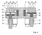
- FIG. 4 shows the actuator in a as in FIG. 3 executed cut.
- the actuating element 12 is completely deflected in the actuating direction 22. It is therefore arranged in the stable position 34.
Landscapes
- Engineering & Computer Science (AREA)
- Mechanical Engineering (AREA)
- General Engineering & Computer Science (AREA)
- Reciprocating, Oscillating Or Vibrating Motors (AREA)
- Electromagnets (AREA)
- Control Of Throttle Valves Provided In The Intake System Or In The Exhaust System (AREA)
- Valve Device For Special Equipments (AREA)
Description
- Die Erfindung betrifft eine Betätigungsvorrichtung nach dem Oberbegriff des Anspruchs 1.
- Aus der
DE 102 11 395 A1 ist eine Betätigungsvorrichtung bekannt, bei welcher aufgrund eines Bestromens einer Spule ein Betätigungsvorgang eines Betätigungselements ausgeführt wird. - Der Erfindung liegt die Aufgabe zugrunde, mit Hilfe einer Betätigungseinheit unter Einsparung von Bauraum, Bauelementen und Kosten bei einer zuverlässigen Funktionsweise Betätigungsvorgänge mehrerer Betätigungselemente auszuführen. Die Aufgabe wird jeweils gelöst durch die Merkmale der unabhängigen Patentansprüche, wobei weitere Ausgestaltungen der Erfindung den Unteransprüchen entnommen werden können.
- Die Erfindung geht aus von einer Betätigungsvorrichtung mit wenigstens einer elektrischen und/oder elektromagnetischen Betätigungseinheit.
- Es wird vorgeschlagen, dass wenigstens zwei von unterschiedlichen Betätigungselementen der Betätigungseinheit ausgeführte Betätigungsvorgänge zumindest zwei unterschiedlichen elektrischen und/oder elektromagnetischen Zuständen der Betätigungseinheit zugeordnet sind. Unter einer "elektrischen und/oder elektromagnetischen Betätigungseinheit" soll insbesondere eine Einheit verstanden werden, welche aufgrund wenigstens eines elektrischen und/oder elektromagnetischen Vorgangs zumindest einen Betätigungsvorgang ausführt. Unter einem "Betätigungsvorgang" soll im Besonderen ein Vorgang verstanden werden, bei welchem eine Einheit und/oder ein Element relativ zu einer weiteren Einheit und/oder einem weiteren Element bewegt wird. Unter einem "Betätigungselement" soll im Besonderen ein Element verstanden werden, welches bei einem Betätigungsvorgang beteiligt ist. Unter einem elektrischen und/oder elektromagnetischen "Zustand" sollen insbesondere Werte einer Stromdichtevektorkomponente und/oder eines elektromagnetischen Feldstärketensors und/oder einer Ladungsdichte innerhalb der Betätigungsvorrichtung und insbesondere an den restlichen Raumpunkten in Verbindung mit den zu den Werten gehörenden Raumkoordinaten verstanden werden. Darunter, dass ein Betätigungsvorgang einem Betätigungselement "zugeordnet" ist, soll insbesondere verstanden werden, dass das Betätigungselement an dem Betätigungsvorgang beteiligt ist. Darunter, dass "zwei Betätigungsvorgänge zwei Betätigungselementen zugeordnet" sind, soll insbesondere verstanden werden, dass jeweils ein Betätigungsvorgang jeweils einem Betätigungselement zugeordnet ist. Unter "unterschiedlichen" elektrischen und/oder elektromagnetischen Zuständen sollen insbesondere Zustände verstanden werden, welche darin verschieden sind, dass wenigstens eine Komponente des Stromdichtevektors und/oder des elektromagnetischen Feldstärketensors und/oder der Ladungsdichte an einem Raumpunkt unterschiedliche Vorzeichen aufweisen. Mit einer erfindungsgemäßen Ausgestaltung kann die Betätigungseinheit kompakt ausgebildet werden.
- In einer bevorzugten Ausführungsform der Erfindung sind die Betätigungsvorgänge unterschiedlichen Stromflussrichtungen zugeordnet, die unterschiedliche elektrische Zustände im oben genannten Sinne darstellen. Unter einer "Stromflussrichtung" soll insbesondere eine Richtung eines Stromflusses verstanden werden. Hiermit kann ein elektrisches und/oder elektromagnetisches Bauelement, welches insbesondere eine Spule und/oder eine Spuleneinheit sein kann, eingespart werden.
- Ferner wird vorgeschlagen, dass die Betätigungseinheit wenigstens eine Spuleneinheit aufweist, die zur Bestromung mit unterschiedlichen Stromflussrichtungen vorgesehen ist. Unter "vorgesehen" soll insbesondere speziell ausgestattet und/oder ausgelegt verstanden werden. Mit einer entsprechenden erfindungsgemäßen Ausgestaltung kann eine einfache Konstruktion der Betätigungseinheit erreicht werden.
- Mit Vorteil weist die Betätigungseinheit wenigstens eine Beschleunigungseinheit auf, welche dazu vorgesehen ist, wenigstens eines der Betätigungselemente zu beschleunigen. Unter einer "Beschleunigung eines Betätigungselements" soll insbesondere eine Beschleunigung des Betätigungselements relativ zu wenigstens einem Teil der Beschleunigungseinheit und/oder relativ zu wenigstens einem Teil der Betätigungseinheit, welche insbesondere eine Spule sein kann, verstanden werden. Mit einer erfindungsgemäßen Ausgestaltung kann ein Betätigungsvorgang schnell ausgeführt werden.
- Außerdem wird vorgeschlagen, dass die Beschleunigungseinheit mit einer Spuleneinheit der Betätigungseinheit zumindest teilweise identisch ist. Hiermit kann ein einfacher Ablauf eines Betätigungsvorgangs erreicht werden.
- In einer bevorzugten Ausgestaltung der Erfindung weist wenigstens eines der Betätigungselemente ein aktives magnetisches Element auf. Unter einem "aktiven magnetischen Element" soll insbesondere sowohl ein elektromagnetisches Element als auch ein Permanentmagnet verstanden werden. Damit können Betätigungsvorgänge unterschiedlicher Betätigungselemente auf einfache Weise in Gang gesetzt werden.
- Vorzugsweise sind wenigstens zwei der Betätigungsvorgänge identischen Betätigungsrichtungen zugeordnet, wobei die identischen Betätigungsrichtungen zugeordneten Betätigungsvorgänge zwei unterschiedlichen der Betätigungselemente zugeordnet sind. Unter einer "Betätigungsrichtung" soll insbesondere eine Richtung verstanden werden, in welche ein Betätigungselement bei einem Betätigungsvorgang relativ zu Teilen der Betätigungseinheit und/oder der Spuleneinheit bewegt wird und besonders vorteilhaft von der Spuleneinheit bewegt wird. Mit einer erfindungsgemäßen Ausgestaltung können Betätigungsvorgänge in voneinander beabstandeten Raumbereichen ausgeführt werden.
- In einer bevorzugten Ausgestaltung der Erfindung umfasst die Betätigungseinheit zumindest ein magnetisches, elektrisches und/oder elektromagnetisches Stabilisierungselement, welches dazu vorgesehen ist, ein Verbleiben wenigstens eines der Betätigungselemente in zumindest einer stabilen Position zu bewirken. Hiermit kann insbesondere ein Betätigungsvorgang zeitlich ausgedehnt werden.
- Ferner wird vorgeschlagen, dass die Betätigungseinheit ein aktives magnetisches Element aufweist, welches wenigstens teilweise mit dem Stabilisierungselement identisch ist. Damit kann eine besonders einfache Konstruktion eines Betätigungselements erreicht werden.
- In einer bevorzugten Ausgestaltung der Erfindung weist die Betätigungseinheit eine Sicherungseinheit auf, welche dazu vorgesehen ist, zu einem Betriebszeitpunkt ausschließlich einem der Betätigungselemente einen der Betätigungsvorgänge zu erlauben. Damit kann insbesondere ein bei simultanen Betätigungsvorgängen mögliches Zerstören wenigstens eines Betätigungselements und/oder eines durch ein Betätigungselement betätigten Bauelements verhindert werden.
- Ferner wird vorgeschlagen, dass die Betätigungseinheit wenigstens eine Spuleneinheit und wenigstens ein aktives magnetisches Element aufweist, welche zusammen wenigstens teilweise die Sicherungseinheit bilden. Hiermit kann bei einer Gewährleistung einer sicheren Betriebsweise eine einfache Konstruktion erreicht werden.
- In einer vorteilhaften Ausgestaltung der Erfindung weist die Betätigungseinheit wenigstens ein mechanisches, pneumatisches und/oder hydraulisches Energiespeicherelement auf, welches dazu vorgesehen ist, bei einem Betätigungsvorgang wenigstens ein Betätigungselement zu beschleunigen. Mit einer erfindungsgemäßen Ausgestaltung kann eine effiziente Verwendung frei werdender Energie erreicht werden.
- Die erfindungsgemäße Betätigungsvorrichtung eignet sich für verschiedene, dem Fachmann als sinnvoll erscheinende Einsatzgebiete, besonders vorteilhaft bildet die Betätigungsvorrichtung jedoch eine Brennkraftmaschinenbetätigungsvorrichtung, und zwar insbesondere für eine Ventiltriebumschalteinheit.
- Dabei zeigen:
- Fig. 1
- einen Schnitt durch eine Betätigungsvorrichtung,
- Fig. 2
- eine Draufsicht auf die Betätigungsvorrichtung,
- Fig. 3
- einen Schnitt durch die Betätigungsvorrichtung und
- Fig. 4
- einen Schnitt durch die Betätigungsvorrichtung.
-
Figur 1 zeigt einen Schnitt durch eine Betätigungsvorrichtung mit einer elektrischen und elektromagnetischen Betätigungseinheit 10. Die Betätigungseinheit 10 weist zwei Betätigungselemente 12, 14 auf. Die Betätigungselemente 12, 14 weisen jeweils eine Haupterstreckungsrichtung auf, wobei die beiden Haupterstreckungsrichtungen miteinander identisch sind. Die Betätigungselemente 12, 14 weisen an jeweils einem Ende ein aktives magnetisches Element 20, 21 auf, welches als Permanentmagnet ausgebildet ist. Die beiden Enden der aktiven Elemente 20, 21 sind einander zugewandt. Eine Verlängerung eines Südpols 36 zu einem Nordpol 38 des aktiven Elements 20 weist in dieselbe Richtung wie eine Verlängerung eines Nordpols 42 zu einem Südpol 40 des aktiven Elements 21, weshalb die beiden aktiven Elemente 20, 21 entgegengesetzt gepolt sind. Die aktiven Elemente 20, 21 besitzen jeweils die Form eines geraden Hohlzylinders. Grund- und Deckflächen der Hohlzylinder sind senkrecht zu den Haupterstreckungsrichtungen. Die Grundflächen der als Hohlzylinder ausgebildeten aktiven Elemente 20, 21 befinden sich in einer gemeinsamen Ebene. Diese Ebene schneidet eine Spuleneinheit 16, welche eine Spule 17 (Figur 3 ) aufweist. Die Spuleneinheit 16 wird ferner von einer Mittelsenkrechten zu zwei Massenmittelpunkten der aktiven Elemente 20, 21, welche parallel zu den Grundflächen ist, geschnitten. Die Spuleneinheit 16 ist neben den aktiven Elementen 20, 21 derart angeordnet, dass mittels eines durch die Spule 17 erzeugten Magnetfelds Kräfte auf die aktiven Elemente 20, 21 ausübbar sind. - Die Betätigungselemente 12, 14 besitzen identische Betätigungsrichtungen 22, 24, welche parallel zu ihrer Haupterstreckungsrichtung und von den aktiven Elementen 20, 21 jeweils zu einem gegenüberliegenden Ende der aktiven Elemente 20, 21 verlaufen. Bei einer Bestromung der Spule 17 (
Figur 3 ) in einer Stromflussrichtung wird eines der Betätigungselemente 12, 14 relativ zu der Spuleneinheit 16 beschleunigt. Die Betätigungseinheit 10 umfasst somit eine Beschleunigungseinheit 18, welche teilweise mit der Spuleneinheit 16 identisch ist. Wird die Spule 17 (Figur 3 ) in einer der Stromflussrichtung entgegengesetzten Stromflussrichtung bestromt, so wird aufgrund der entgegengesetzten Polung der aktiven Elemente 20, 21 das andere Betätigungselemente 12, 14 relativ zu der Spuleneinheit 16 beschleunigt. Eine Bewegung eines der Betätigungselemente 12, 14 relativ zu der Spuleneinheit 16 in die Betätigungsrichtungen 22, 24 ist ein Betätigungsvorgang, welcher dem sich bewegenden Betätigungselement 12, 14 zugeordnet ist. Da die Betätigungselemente 12, 14 mittels unterschiedlicher Stromflussrichtungen beschleunigt werden, sind die Betätigungsvorgänge unterschiedlichen Stromflussrichtungen zugeordnet. Eine Stromflussrichtung stellt einen elektrischen und elektromagnetischen Zustand der Betätigungseinheit 10 dar. Demzufolge sind zwei von den unterschiedlichen Betätigungselementen 12, 14 der Betätigungseinheit 10 ausgeführte Betätigungsvorgänge zumindest zwei der unterschiedlichen elektrischen und elektromagnetischen Zustände der Betätigungseinheit 10 zugeordnet. Einer der Betätigungsvorgänge, welcher von einem der Betätigungselemente 12, 14 ausgeführt wird, ist diesem Betätigungselement 12, 14 zugeordnet. Die beiden Betätigungselemente 12, 14 führen die ihnen zugeordneten Betätigungsvorgänge in dieselbe Betätigungsrichtung 22, 24 aus. Demzufolge sind wenigstens zwei der Betätigungsvorgänge den identischen Betätigungsrichtungen 22, 24 zugeordnet, wobei die identischen Betätigungsrichtungen 22, 24 zugeordneten Betätigungsvorgänge zwei unterschiedlichen der Betätigungselemente 12, 14 zugeordnet sind. - Ferner umfasst die Betätigungseinheit 10 zwei magnetische, elektrische und elektromagnetische Stabilisierungselemente 26, 27. Die Stabilisierungselemente 26 bzw. 27 sind dazu vorgesehen, ein Verbleiben der Betätigungselemente 12 bzw. 14 in zumindest einer stabilen Position 28 bzw. 29 zu bewirken. Die Stabilisierungselemente 26 bzw. 27 sind mit den aktiven Elementen 20, 21 identisch. Eine Bewegung der Betätigungselemente 12, 14 relativ zu der Spuleneinheit 16 ist in die Betätigungsrichtung 22 durch Oberflächen einer Umhüllungseinheit 46 begrenzt. Die Umhüllungseinheit 46 umhüllt die Betätigungselemente 12, 14. Da die Oberflächen zumindest teilweise aus einem Material gebildet sind, welches eine Kraft auf einen Permanentmagneten ausüben kann, werden die aktiven Elemente 20, 21 von den Oberflächen und einem darunter liegenden Material angezogen und so in einer stabilen Position 34 (
Figur 4 ) gehalten. Ferner wird eine Bewegung einer der Betätigungselemente 12, 14 in die Gegenrichtung der Betätigungsrichtung 22 durch eine Halteeinheit 44 begrenzt, welche mit der Spuleneinheit 16 verbunden ist. Da die Halteeinheit 44 zumindest teilweise aus einem Material gebildet ist, welches eine Kraft auf einen Permanentmagneten ausüben kann, bewirkt das Stabilisierungselement 26, 27 mittels einer auf dieses von der Halteeinheit 44 ausgeübten Kraft ein Verbleiben des Betätigungselements 12, 14 in der maximal in die Gegenrichtung der Betätigungsrichtung 22 ausgelenkten stabilen Position 28, 29. - Nach einem Betätigungsvorgang eines der Betätigungselemente 12, 14 wird das betreffende Betätigungselement 12, 14 wieder in die stabile Position 28 bzw. 29 zurückbewegt. Danach findet eine Bestromung der Spule (
Figur 3 ) mit einer Stromdurchflussrichtung statt, welche der Stromdurchflussrichtung entgegengesetzt ist, welche zu einem Beschleunigen des Betätigungselements 12, 14 verwendet wurde. Die Betätigungseinheit 10 weist daher eine Sicherungseinheit 30 in Form der Spule 17 (Figur 3 ) und der aktiven Elemente 20, 21 auf, welche dazu vorgesehen ist, zu einem Betriebszeitpunkt ausschließlich einem der Betätigungselemente 12, 14 einen der Betätigungsvorgänge zu erlauben. - Außerdem weist die Betätigungseinheit 10 zwei als Schraubenfedern ausgebildete mechanische Energiespeicherelemente 32, 33 auf, welche dazu vorgesehen sind, bei den Betätigungsvorgängen die Betätigungselemente 12, 14 relativ zu der Spuleneinheit zu beschleunigen. Die Schraubenfedern sind zwischen den Betätigungselementen 12, 14 und der Halteeinheit 44 angeordnet und befinden sich, wenn sich die Betätigungselemente 12, 14 in den stabilen Positionen 28, 29 befinden, in komprimiertem Zustand. Bei einem Betätigungsvorgang dekomprimiert eines der Energiespeicherelemente 32, 33 und beschleunigt eines der Betätigungselemente 12, 14.
-
Figur 2 zeigt eine Draufsicht von oben auf eine Betätigungsvorrichtung in die Betätigungsrichtung 22. Die Halteeinheit 44 verdeckt teilweise die Spuleneinheit 16, die Umhüllungseinheit 46 und die Betätigungselemente 12, 14. Zwei abgeschlossene Halbebenen 48, 50 sind in der Figur projizierend dargestellt. Die Halbebenen 48, 50 schneiden sich in einer Gerade, welche die beide Halbebenen 48, 50 in Ebenen, in welchen sich die Halbebenen 48, 50 erstrecken, begrenzen. Die Gerade schneidet die Spuleneinheit mittig. Die Halbebene 48 schneidet das Betätigungselement 14 mittig, die andere Halbebene 50 schneidet das Betätigungselement 12 mittig. -
Figur 3 zeigt die Betätigungsvorrichtung in einem Schnitt entlang der Halbebenen 48, 50 (Figur 2 ), so dass die Spuleneinheit 16 und die Betätigungselemente 12, 14 sichtbar sind. Die Spuleneinheit 16 weist die Spule 17 auf. Die Betätigungselemente 12, 14 befinden sich in den stabilen Positionen 28, 29. Die Spule 17 kann an einer Stelle in einer Richtung orthogonal zu der Betätigungsrichtung 22 (Figur 1 ) Strom führen und damit einen Betätigungsvorgang eines der Betätigungselemente 12, 14 auslösen. Die Spule 17 kann ebenfalls in der zu der orthogonalen Richtung entgegengesetzten Richtung Strom führen und damit einen Betätigungsvorgang des anderen Betätigungselements 12, 14 auslösen. -
Figur 4 zeigt die Betätigungsvorrichtung in einem wie inFigur 3 ausgeführten Schnitt. Das Betätigungselement 12 ist vollständig in die Betätigungsrichtung 22 ausgelenkt. Es ist daher in der stabilen Position 34 angeordnet.
Claims (11)
- Betätigungsvorrichtung für eine Ventiltriebumschalteinheit einer Brennkraftmaschine, mit wenigstens einer elektrischen und/oder elektromagnetischen Betätigungseinheit (10), die wenigstens zwei bewegliche Betätigungselemente (12, 14) aufweist, die an jeweils einem Ende ein als Permanentmagnet ausgebildetes aktives magnetisches Element (20, 21) aufweisen, welche entgegengesetzt gepolt sind, wobei Betätigungsvorgänge der unterschiedlichen Betätigungselemente (12, 14) zumindest zwei unterschiedlichen elektrischen und/oder elektromagnetischen Zuständen der Betätigungseinheit (10) zugeordnet sind, wobei die Betätigungseinheit (10) wenigstens eine Spuleneinheit (16) aufweist, die zur Bestromung mit unterschiedlichen Stromflussrichtungen vorgesehen ist, die die unterschiedlichen elektrischen und/oder elektromagnetischen Zustände der Betätigungseinheit (10) darstellen,
dadurch gekennzeichnet, dass
die Spuleneinheit (16) neben den aktiven Elementen (20, 21) derart angeordnet ist, dass mittels eines durch eine Spule (17) der Spuleneinheit (16) erzeugten Magnetfelds Kräfte auf die aktiven Elemente (20, 21) ausübbar sind, wobei bei einer Bestromung der Spule (17) in einer Stromflussrichtung eines der Betätigungselemente (12, 14) relativ zu der Spuleneinheit (16) beschleunigt wird und bei einer Bestromung in einer entgegengesetzten Stromflussrichtung aufgrund der entgegengesetzten Polung der aktiven Elemente (20, 21) das andere Betätigungselement (12, 14) beschleunigt wird. - Brennkraftmaschinenbetätigungsvorrichtung nach Anspruch 1,
dadurch gekennzeichnet, dass
die Betätigungsvorgänge unterschiedlichen Stromflussrichtungen zugeordnet sind. - Brennkraftmaschinenbetätigungsvorrichtung nach einem der vorhergehenden Ansprüche,
dadurch gekennzeichnet, dass
die Betätigungseinheit wenigstens eine Beschleunigungseinheit (18) aufweist, welche dazu vorgesehen ist, wenigstens eines der Betätigungselemente (12, 14) zu beschleunigen. - Brennkraftmaschinenbetätigungsvorrichtung nach Anspruch 3,
dadurch gekennzeichnet, dass
die Beschleunigungseinheit (18) mit einer Spuleneinheit (16) der Betätigungseinheit (10) zumindest teilweise identisch ist. - Brennkraftmaschinenbetätigungsvorrichtung nach einem der vorherigen Ansprüche,
dadurch gekennzeichnet, dass
wenigstens zwei der Betätigungsvorgänge identischen Betätigungsrichtungen (22, 24) zugeordnet sind, wobei die identischen Betätigungsrichtungen (22, 24) zugeordneten Betätigungsvorgänge zwei unterschiedlichen der Betätigungselemente (12, 14) zugeordnet sind. - Brennkraftmaschinenbetätigungsvorrichtung nach einem der vorherigen Ansprüche,
dadurch gekennzeichnet, dass
die Betätigungseinheit (10) zumindest ein magnetisches, elektrisches und/oder elektromagnetisches Stabilisierungselement (26, 27) umfasst, welches dazu vorgesehen ist, ein Verbleiben wenigstens eines der Betätigungselemente (12, 14) in zumindest einer stabilen Position (28, 29, 34) zu bewirken. - Brennkraftmaschinenbetätigungsvorrichtung nach Anspruch 6,
dadurch gekennzeichnet, dass
die Betätigungseinheit ein aktives magnetisches Element (20, 21) aufweist, welches wenigstens teilweise mit dem Stabilisierungselement (26, 27) identisch ist. - Brennkraftmaschinenbetätigungsvorrichtung nach einem der vorherigen Ansprüche,
dadurch gekennzeichnet, dass
die Betätigungseinheit (10) eine Sicherungseinheit (30) aufweist, welche dazu vorgesehen ist, zu einem Betriebszeitpunkt ausschließlich einem der Betätigungselemente (12, 14) einen der Betätigungsvorgänge zu erlauben. - Brennkraftmaschinenbetätigungsvorrichtung nach Anspruch 8,
dadurch gekennzeichnet, dass
die Betätigungseinheit wenigstens eine Spuleneinheit (16) und wenigstens ein aktives magnetisches Element (20, 21) aufweist, welche zusammen wenigstens teilweise die Sicherungseinheit (30) bilden. - Brennkraftmaschinenbetätigungsvorrichtung nach einem der vorherigen Ansprüche,
dadurch gekennzeichnet, dass
die Betätigungseinheit (10) wenigstens ein mechanisches, pneumatisches und/oder hydraulisches Energiespeicherelement (32) aufweist, welches dazu vorgesehen ist, bei einem Betätigungsvorgang wenigstens eines der Betätigungselemente (12, 14) zu beschleunigen. - Betätigungsverfahren für eine Ventiltriebumschalteinheit einer Brennkraftmaschine, mit wenigstens einer elektrischen und/oder elektromagnetischen Betätigungseinheit (10), die wenigstens zwei bewegliche Betätigungselemente (12, 14) aufweist, die an jeweils einem Ende ein als Permanentmagnet ausgebildetes aktives magnetisches Element (20, 21) aufweisen, welche entgegengesetzt gepolt sind, wobei wenigstens zwei von unterschiedlichen Betätigungselementen (12, 14) der Betätigungseinheit (10) ausgeführte Betätigungsvorgänge ausgeführt werden, die zumindest zwei unterschiedlichen elektrischen und/oder elektromagnetischen Zuständen zugeordnet sind,
dadurch gekennzeichnet, dass
mittels eines durch eine Spule (17) einer Spuleneinheit (16) erzeugten Magnetfelds Kräfte auf die aktiven Elemente (20, 21) ausgeübt werden, wobei bei einer Bestromung der Spule (17) in einer Stromflussrichtung eines der Betätigungselemente (12, 14) relativ zu der Spuleneinheit (16) beschleunigt wird und bei einer Bestromung in einer entgegengesetzten Stromflussrichtung aufgrund der entgegengesetzten Polung der aktiven Elemente (20, 21) das andere Betätigungselement (12, 14) beschleunigt wird.
Applications Claiming Priority (2)
| Application Number | Priority Date | Filing Date | Title |
|---|---|---|---|
| DE102007037333A DE102007037333A1 (de) | 2007-08-08 | 2007-08-08 | Betätigungsvorrichtung |
| PCT/EP2008/006016 WO2009018919A1 (de) | 2007-08-08 | 2008-07-23 | Betätigungsvorrichtung |
Publications (2)
| Publication Number | Publication Date |
|---|---|
| EP2176525A1 EP2176525A1 (de) | 2010-04-21 |
| EP2176525B1 true EP2176525B1 (de) | 2012-09-12 |
Family
ID=39968015
Family Applications (1)
| Application Number | Title | Priority Date | Filing Date |
|---|---|---|---|
| EP08784975A Active EP2176525B1 (de) | 2007-08-08 | 2008-07-23 | Betätigungsvorrichtung |
Country Status (6)
| Country | Link |
|---|---|
| US (1) | US8235011B2 (de) |
| EP (1) | EP2176525B1 (de) |
| JP (1) | JP5216089B2 (de) |
| CN (1) | CN101772624B (de) |
| DE (1) | DE102007037333A1 (de) |
| WO (1) | WO2009018919A1 (de) |
Families Citing this family (14)
| Publication number | Priority date | Publication date | Assignee | Title |
|---|---|---|---|---|
| DE202008015980U1 (de) * | 2008-12-03 | 2010-06-02 | Eto Magnetic Gmbh | Elektromagnetische Aktuatorvorrichtung |
| DE202009015466U1 (de) * | 2009-02-27 | 2010-03-18 | Schaeffler Kg | Elektromagnetische Stellvorrichtung |
| DE102009056609A1 (de) | 2009-12-02 | 2011-06-09 | Schaeffler Technologies Gmbh & Co. Kg | Elektromagnetische Stellvorrichtung |
| JP5852918B2 (ja) * | 2012-02-09 | 2016-02-03 | 株式会社日本自動車部品総合研究所 | ソレノイド装置及び電磁継電器 |
| DE102013206311A1 (de) * | 2012-05-14 | 2013-11-14 | Denso Corporation | Elektromagnetischer Aktor |
| JP6035965B2 (ja) * | 2012-08-02 | 2016-11-30 | 株式会社デンソー | 電磁アクチュエータ |
| DE102013102241A1 (de) * | 2013-03-06 | 2014-09-11 | Kendrion (Villingen) Gmbh | Elektromagnetische Stellvorrichtung, insbesondere zur Nockenwellenverstellung einer Brennkraftmaschine |
| US9574677B2 (en) | 2013-05-31 | 2017-02-21 | Dayco Ip Holdings, Llc | Solenoid-powered gate valve |
| EP3922888B1 (de) | 2013-05-31 | 2024-11-06 | Dayco IP Holdings, LLC | Durch einen aktuator bewegbare, gefederte schieberventile |
| WO2015031770A1 (en) | 2013-08-30 | 2015-03-05 | Dayco Ip Holdings, Llc | Sprung gate valves movable by a solenoid actuator |
| US10221867B2 (en) | 2013-12-10 | 2019-03-05 | Dayco Ip Holdings, Llc | Flow control for aspirators producing vacuum using the venturi effect |
| CN104903635B (zh) * | 2013-12-11 | 2017-03-15 | 戴科知识产权控股有限责任公司 | 磁致动的截止阀 |
| EP3016117B1 (de) * | 2014-10-31 | 2017-12-06 | Husco Automotive Holdings LLC | Druckstiftaktuatorvorrichtung |
| US9599246B2 (en) | 2015-08-05 | 2017-03-21 | Dayco Ip Holdings, Llc | Magnetically actuated shut-off valve |
Family Cites Families (28)
| Publication number | Priority date | Publication date | Assignee | Title |
|---|---|---|---|---|
| GB573405A (en) * | 1942-09-14 | 1945-11-20 | Standard Telephones Cables Ltd | Electrical control system |
| GB612608A (en) * | 1944-02-14 | 1948-11-16 | Sperry Gyroscope Co Inc | Improvements relating to the precession of gyroscopes and to precession control systems and gyroscopes so controlled |
| GB616494A (en) * | 1945-01-23 | 1949-01-21 | British Thomson Houston Co Ltd | Improvements in and relating to electric motor control systems |
| GB637785A (en) * | 1945-04-04 | 1950-05-24 | British Thomson Houston Co Ltd | Improvements in and relating to screwdown control systems for rolling mills |
| GB692659A (en) * | 1951-03-14 | 1953-06-10 | Electrical & Auto Products 193 | Improvements relating to electrical testing apparatus |
| GB726878A (en) * | 1953-07-21 | 1955-03-23 | Communications Patents Ltd | Improvements in or relating to flight and navigational training apparatus |
| US2980090A (en) * | 1956-02-24 | 1961-04-18 | Bendix Corp | Fuel injection system |
| GB913536A (en) * | 1960-05-31 | 1962-12-19 | Lucas Industries Ltd | Control means for electromagnetically actuated twin horns on road vehicles |
| DE3826978A1 (de) * | 1988-08-09 | 1990-02-15 | Meyer Hans Wilhelm | Elektromagnetisch betaetigbare stellvorrichtung |
| US5070489A (en) * | 1989-08-01 | 1991-12-03 | Eastman Kodak Company | Driving circuit for double solenoid focus actuator |
| JPH0466747U (de) * | 1990-10-23 | 1992-06-12 | ||
| JP2569948B2 (ja) * | 1990-11-08 | 1997-01-08 | 富士通株式会社 | 双子型電磁継電器 |
| US5109812A (en) * | 1991-04-04 | 1992-05-05 | North American Philips Corporation | Pneumatic preloaded actuator |
| US5404908A (en) * | 1994-02-14 | 1995-04-11 | Marotta Scientific Controls, Inc. | Magnetically linked multi-valve system |
| JP2716007B2 (ja) * | 1995-07-14 | 1998-02-18 | 日本電気株式会社 | 双子型有極電磁リレー |
| US6158404A (en) * | 1997-02-26 | 2000-12-12 | Aft Atlas Fahrzeugtechnik Gmbh | Apparatus for regulating the operation of an adjusting device |
| US6176208B1 (en) * | 1997-07-03 | 2001-01-23 | Nippon Soken, Inc. | Electromagnetic valve driving apparatus |
| DE19816878C2 (de) * | 1998-04-17 | 2003-11-13 | Hengstler Gmbh | Zwillingsrelais |
| JP4073584B2 (ja) * | 1998-11-04 | 2008-04-09 | 株式会社ミクニ | 弁駆動装置 |
| DE19851507A1 (de) * | 1998-11-09 | 2000-05-11 | Hengstler Gmbh | Relais mit Koppelelement |
| ATE296944T1 (de) | 1999-03-31 | 2005-06-15 | Fev Motorentech Gmbh | Gaswechselventilanordnung mit elektromagnetischem aktuator |
| JP2000315448A (ja) * | 1999-05-06 | 2000-11-14 | Omron Corp | 電磁リレー |
| JP3994586B2 (ja) * | 1999-07-12 | 2007-10-24 | トヨタ自動車株式会社 | 内燃機関の弁駆動装置 |
| FR2808375B1 (fr) | 2000-04-27 | 2002-09-06 | Sagem | Actionneur electromagnetique de soupape, de type monobobine |
| DE10211395A1 (de) | 2002-03-15 | 2003-10-09 | Ina Schaeffler Kg | Betätigungsmittel für einen schaltbaren Ventiltrieb einer Brennkraftmaschine |
| DE202004002268U1 (de) | 2004-02-13 | 2005-06-23 | Hawe Hydraulik Gmbh & Co. Kg | Mehrwege-Doppelsitzventil mit Magnetbetätigung |
| DE202004002432U1 (de) | 2004-02-17 | 2005-07-07 | Hawe Hydraulik Gmbh & Co. Kg | Magnetdoppelventil |
| JP2007046498A (ja) * | 2005-08-08 | 2007-02-22 | Toyota Motor Corp | 電磁駆動弁 |
-
2007
- 2007-08-08 DE DE102007037333A patent/DE102007037333A1/de not_active Withdrawn
-
2008
- 2008-07-23 WO PCT/EP2008/006016 patent/WO2009018919A1/de not_active Ceased
- 2008-07-23 CN CN2008801019756A patent/CN101772624B/zh not_active Expired - Fee Related
- 2008-07-23 EP EP08784975A patent/EP2176525B1/de active Active
- 2008-07-23 JP JP2010519355A patent/JP5216089B2/ja not_active Expired - Fee Related
-
2010
- 2010-02-05 US US12/658,586 patent/US8235011B2/en not_active Expired - Fee Related
Also Published As
| Publication number | Publication date |
|---|---|
| JP2010535962A (ja) | 2010-11-25 |
| CN101772624B (zh) | 2012-07-11 |
| CN101772624A (zh) | 2010-07-07 |
| US20100180850A1 (en) | 2010-07-22 |
| DE102007037333A1 (de) | 2009-02-26 |
| US8235011B2 (en) | 2012-08-07 |
| JP5216089B2 (ja) | 2013-06-19 |
| WO2009018919A1 (de) | 2009-02-12 |
| EP2176525A1 (de) | 2010-04-21 |
Similar Documents
| Publication | Publication Date | Title |
|---|---|---|
| EP2176525A1 (de) | Betätigungsvorrichtung | |
| EP1430490B1 (de) | Elektromagnetischer aktuator | |
| EP3191695B1 (de) | Elektromagnetische stellvorrichtung | |
| EP0686989B1 (de) | Bistabile Schaltvorrichtung | |
| DE102011014192B4 (de) | Elektromagnetische Aktuatorvorrichtung | |
| DE102013215201A1 (de) | Blinkerschalter sowie Verfahren zur Rückstellung eines Blinkerschalters | |
| DE102015221800A1 (de) | Greifeinrichtung | |
| EP1859462A1 (de) | Magnetische betätigungsvorrichtung | |
| EP0796503B1 (de) | Polarisiertes relais | |
| DE102004059342B4 (de) | Greif- oder Spannvorrichtung | |
| DE3539976A1 (de) | Abschaltvorrichtung mit fernsteuerung der oeffnung und schliessung ihrer kreise | |
| DE102008024940B3 (de) | Relais | |
| DE102013215202B4 (de) | Blinkerschalter sowie Verfahren zur Rückstellung eines Blinkerschalters | |
| DE102007058110B4 (de) | Schalter | |
| EP0008660B1 (de) | Anordnung in Form eines symmetrischen Magnethaltesystems für Auslösevorrichtungen mit einem Bewegungselement, z.B. einem Druckhammer | |
| DE2165538C3 (de) | Steuervorrichtung für eine Flachstrickmaschine | |
| DE102011081893B3 (de) | Magnetischer Aktor und Verfahren zu dessen Betrieb | |
| EP1897108B1 (de) | Elektrische schaltvorrichtung mit magnetischen verstellelementen für ein schaltelement | |
| DE102019119125A1 (de) | Greifvorrichtung | |
| DE3004769A1 (de) | Haarschneideeinrichtung | |
| DE102020122839A1 (de) | Schaltbare Magnetvorrichtung | |
| DE102008063689B4 (de) | Elektromagnet mit Permanentmagnet | |
| DE102016109547A1 (de) | Abtastschablone | |
| DE267556C (de) | ||
| DE2120357C3 (de) | Vorrichtung zur schrittweisen Fortschaltung eines Schaltrades zum Antrieb von Zeitmeß gerätea |
Legal Events
| Date | Code | Title | Description |
|---|---|---|---|
| PUAI | Public reference made under article 153(3) epc to a published international application that has entered the european phase |
Free format text: ORIGINAL CODE: 0009012 |
|
| 17P | Request for examination filed |
Effective date: 20100126 |
|
| AK | Designated contracting states |
Kind code of ref document: A1 Designated state(s): AT BE BG CH CY CZ DE DK EE ES FI FR GB GR HR HU IE IS IT LI LT LU LV MC MT NL NO PL PT RO SE SI SK TR |
|
| AX | Request for extension of the european patent |
Extension state: AL BA MK RS |
|
| DAX | Request for extension of the european patent (deleted) | ||
| 17Q | First examination report despatched |
Effective date: 20110214 |
|
| REG | Reference to a national code |
Ref country code: DE Ref legal event code: R079 Ref document number: 502008008183 Country of ref document: DE Free format text: PREVIOUS MAIN CLASS: F01L0013060000 Ipc: F02D0041040000 |
|
| GRAP | Despatch of communication of intention to grant a patent |
Free format text: ORIGINAL CODE: EPIDOSNIGR1 |
|
| RIC1 | Information provided on ipc code assigned before grant |
Ipc: F02D 41/04 20060101AFI20120227BHEP Ipc: F16K 11/14 20060101ALI20120227BHEP Ipc: F01L 13/06 20060101ALI20120227BHEP |
|
| GRAS | Grant fee paid |
Free format text: ORIGINAL CODE: EPIDOSNIGR3 |
|
| GRAA | (expected) grant |
Free format text: ORIGINAL CODE: 0009210 |
|
| AK | Designated contracting states |
Kind code of ref document: B1 Designated state(s): AT BE BG CH CY CZ DE DK EE ES FI FR GB GR HR HU IE IS IT LI LT LU LV MC MT NL NO PL PT RO SE SI SK TR |
|
| REG | Reference to a national code |
Ref country code: GB Ref legal event code: FG4D Free format text: NOT ENGLISH |
|
| REG | Reference to a national code |
Ref country code: CH Ref legal event code: EP |
|
| REG | Reference to a national code |
Ref country code: AT Ref legal event code: REF Ref document number: 575210 Country of ref document: AT Kind code of ref document: T Effective date: 20120915 |
|
| REG | Reference to a national code |
Ref country code: IE Ref legal event code: FG4D Free format text: LANGUAGE OF EP DOCUMENT: GERMAN |
|
| REG | Reference to a national code |
Ref country code: DE Ref legal event code: R096 Ref document number: 502008008183 Country of ref document: DE Effective date: 20121108 |
|
| PG25 | Lapsed in a contracting state [announced via postgrant information from national office to epo] |
Ref country code: FI Free format text: LAPSE BECAUSE OF FAILURE TO SUBMIT A TRANSLATION OF THE DESCRIPTION OR TO PAY THE FEE WITHIN THE PRESCRIBED TIME-LIMIT Effective date: 20120912 Ref country code: CY Free format text: LAPSE BECAUSE OF FAILURE TO SUBMIT A TRANSLATION OF THE DESCRIPTION OR TO PAY THE FEE WITHIN THE PRESCRIBED TIME-LIMIT Effective date: 20120912 Ref country code: HR Free format text: LAPSE BECAUSE OF FAILURE TO SUBMIT A TRANSLATION OF THE DESCRIPTION OR TO PAY THE FEE WITHIN THE PRESCRIBED TIME-LIMIT Effective date: 20120912 Ref country code: NO Free format text: LAPSE BECAUSE OF FAILURE TO SUBMIT A TRANSLATION OF THE DESCRIPTION OR TO PAY THE FEE WITHIN THE PRESCRIBED TIME-LIMIT Effective date: 20121212 Ref country code: LT Free format text: LAPSE BECAUSE OF FAILURE TO SUBMIT A TRANSLATION OF THE DESCRIPTION OR TO PAY THE FEE WITHIN THE PRESCRIBED TIME-LIMIT Effective date: 20120912 |
|
| REG | Reference to a national code |
Ref country code: NL Ref legal event code: VDEP Effective date: 20120912 |
|
| REG | Reference to a national code |
Ref country code: LT Ref legal event code: MG4D Effective date: 20120912 |
|
| PG25 | Lapsed in a contracting state [announced via postgrant information from national office to epo] |
Ref country code: LV Free format text: LAPSE BECAUSE OF FAILURE TO SUBMIT A TRANSLATION OF THE DESCRIPTION OR TO PAY THE FEE WITHIN THE PRESCRIBED TIME-LIMIT Effective date: 20120912 Ref country code: SE Free format text: LAPSE BECAUSE OF FAILURE TO SUBMIT A TRANSLATION OF THE DESCRIPTION OR TO PAY THE FEE WITHIN THE PRESCRIBED TIME-LIMIT Effective date: 20120912 Ref country code: GR Free format text: LAPSE BECAUSE OF FAILURE TO SUBMIT A TRANSLATION OF THE DESCRIPTION OR TO PAY THE FEE WITHIN THE PRESCRIBED TIME-LIMIT Effective date: 20121213 Ref country code: SI Free format text: LAPSE BECAUSE OF FAILURE TO SUBMIT A TRANSLATION OF THE DESCRIPTION OR TO PAY THE FEE WITHIN THE PRESCRIBED TIME-LIMIT Effective date: 20120912 |
|
| PG25 | Lapsed in a contracting state [announced via postgrant information from national office to epo] |
Ref country code: RO Free format text: LAPSE BECAUSE OF FAILURE TO SUBMIT A TRANSLATION OF THE DESCRIPTION OR TO PAY THE FEE WITHIN THE PRESCRIBED TIME-LIMIT Effective date: 20120912 Ref country code: NL Free format text: LAPSE BECAUSE OF FAILURE TO SUBMIT A TRANSLATION OF THE DESCRIPTION OR TO PAY THE FEE WITHIN THE PRESCRIBED TIME-LIMIT Effective date: 20120912 Ref country code: CZ Free format text: LAPSE BECAUSE OF FAILURE TO SUBMIT A TRANSLATION OF THE DESCRIPTION OR TO PAY THE FEE WITHIN THE PRESCRIBED TIME-LIMIT Effective date: 20120912 Ref country code: IS Free format text: LAPSE BECAUSE OF FAILURE TO SUBMIT A TRANSLATION OF THE DESCRIPTION OR TO PAY THE FEE WITHIN THE PRESCRIBED TIME-LIMIT Effective date: 20130112 Ref country code: EE Free format text: LAPSE BECAUSE OF FAILURE TO SUBMIT A TRANSLATION OF THE DESCRIPTION OR TO PAY THE FEE WITHIN THE PRESCRIBED TIME-LIMIT Effective date: 20120912 Ref country code: ES Free format text: LAPSE BECAUSE OF FAILURE TO SUBMIT A TRANSLATION OF THE DESCRIPTION OR TO PAY THE FEE WITHIN THE PRESCRIBED TIME-LIMIT Effective date: 20121223 |
|
| PG25 | Lapsed in a contracting state [announced via postgrant information from national office to epo] |
Ref country code: SK Free format text: LAPSE BECAUSE OF FAILURE TO SUBMIT A TRANSLATION OF THE DESCRIPTION OR TO PAY THE FEE WITHIN THE PRESCRIBED TIME-LIMIT Effective date: 20120912 Ref country code: PL Free format text: LAPSE BECAUSE OF FAILURE TO SUBMIT A TRANSLATION OF THE DESCRIPTION OR TO PAY THE FEE WITHIN THE PRESCRIBED TIME-LIMIT Effective date: 20120912 Ref country code: PT Free format text: LAPSE BECAUSE OF FAILURE TO SUBMIT A TRANSLATION OF THE DESCRIPTION OR TO PAY THE FEE WITHIN THE PRESCRIBED TIME-LIMIT Effective date: 20130114 |
|
| PLBE | No opposition filed within time limit |
Free format text: ORIGINAL CODE: 0009261 |
|
| STAA | Information on the status of an ep patent application or granted ep patent |
Free format text: STATUS: NO OPPOSITION FILED WITHIN TIME LIMIT |
|
| PG25 | Lapsed in a contracting state [announced via postgrant information from national office to epo] |
Ref country code: DK Free format text: LAPSE BECAUSE OF FAILURE TO SUBMIT A TRANSLATION OF THE DESCRIPTION OR TO PAY THE FEE WITHIN THE PRESCRIBED TIME-LIMIT Effective date: 20120912 Ref country code: BG Free format text: LAPSE BECAUSE OF FAILURE TO SUBMIT A TRANSLATION OF THE DESCRIPTION OR TO PAY THE FEE WITHIN THE PRESCRIBED TIME-LIMIT Effective date: 20121212 |
|
| 26N | No opposition filed |
Effective date: 20130613 |
|
| PG25 | Lapsed in a contracting state [announced via postgrant information from national office to epo] |
Ref country code: IT Free format text: LAPSE BECAUSE OF FAILURE TO SUBMIT A TRANSLATION OF THE DESCRIPTION OR TO PAY THE FEE WITHIN THE PRESCRIBED TIME-LIMIT Effective date: 20120912 |
|
| REG | Reference to a national code |
Ref country code: DE Ref legal event code: R097 Ref document number: 502008008183 Country of ref document: DE Effective date: 20130613 |
|
| PGFP | Annual fee paid to national office [announced via postgrant information from national office to epo] |
Ref country code: GB Payment date: 20130731 Year of fee payment: 6 Ref country code: FR Payment date: 20130730 Year of fee payment: 6 |
|
| BERE | Be: lapsed |
Owner name: DAIMLER A.G. Effective date: 20130731 |
|
| PG25 | Lapsed in a contracting state [announced via postgrant information from national office to epo] |
Ref country code: MC Free format text: LAPSE BECAUSE OF FAILURE TO SUBMIT A TRANSLATION OF THE DESCRIPTION OR TO PAY THE FEE WITHIN THE PRESCRIBED TIME-LIMIT Effective date: 20120912 |
|
| REG | Reference to a national code |
Ref country code: CH Ref legal event code: PL |
|
| REG | Reference to a national code |
Ref country code: IE Ref legal event code: MM4A |
|
| PG25 | Lapsed in a contracting state [announced via postgrant information from national office to epo] |
Ref country code: CH Free format text: LAPSE BECAUSE OF NON-PAYMENT OF DUE FEES Effective date: 20130731 Ref country code: LI Free format text: LAPSE BECAUSE OF NON-PAYMENT OF DUE FEES Effective date: 20130731 Ref country code: BE Free format text: LAPSE BECAUSE OF NON-PAYMENT OF DUE FEES Effective date: 20130731 |
|
| PG25 | Lapsed in a contracting state [announced via postgrant information from national office to epo] |
Ref country code: IE Free format text: LAPSE BECAUSE OF NON-PAYMENT OF DUE FEES Effective date: 20130723 |
|
| REG | Reference to a national code |
Ref country code: AT Ref legal event code: MM01 Ref document number: 575210 Country of ref document: AT Kind code of ref document: T Effective date: 20130723 |
|
| PG25 | Lapsed in a contracting state [announced via postgrant information from national office to epo] |
Ref country code: AT Free format text: LAPSE BECAUSE OF NON-PAYMENT OF DUE FEES Effective date: 20130723 |
|
| GBPC | Gb: european patent ceased through non-payment of renewal fee |
Effective date: 20140723 |
|
| REG | Reference to a national code |
Ref country code: FR Ref legal event code: ST Effective date: 20150331 |
|
| PG25 | Lapsed in a contracting state [announced via postgrant information from national office to epo] |
Ref country code: FR Free format text: LAPSE BECAUSE OF NON-PAYMENT OF DUE FEES Effective date: 20140731 Ref country code: GB Free format text: LAPSE BECAUSE OF NON-PAYMENT OF DUE FEES Effective date: 20140723 |
|
| PG25 | Lapsed in a contracting state [announced via postgrant information from national office to epo] |
Ref country code: MT Free format text: LAPSE BECAUSE OF FAILURE TO SUBMIT A TRANSLATION OF THE DESCRIPTION OR TO PAY THE FEE WITHIN THE PRESCRIBED TIME-LIMIT Effective date: 20120912 Ref country code: TR Free format text: LAPSE BECAUSE OF FAILURE TO SUBMIT A TRANSLATION OF THE DESCRIPTION OR TO PAY THE FEE WITHIN THE PRESCRIBED TIME-LIMIT Effective date: 20120912 |
|
| PG25 | Lapsed in a contracting state [announced via postgrant information from national office to epo] |
Ref country code: LU Free format text: LAPSE BECAUSE OF NON-PAYMENT OF DUE FEES Effective date: 20130723 Ref country code: HU Free format text: LAPSE BECAUSE OF FAILURE TO SUBMIT A TRANSLATION OF THE DESCRIPTION OR TO PAY THE FEE WITHIN THE PRESCRIBED TIME-LIMIT; INVALID AB INITIO Effective date: 20080723 |
|
| REG | Reference to a national code |
Ref country code: DE Ref legal event code: R081 Ref document number: 502008008183 Country of ref document: DE Owner name: MERCEDES-BENZ GROUP AG, DE Free format text: FORMER OWNER: DAIMLER AG, 70327 STUTTGART, DE Ref country code: DE Ref legal event code: R082 Ref document number: 502008008183 Country of ref document: DE Representative=s name: JENSEN & SON, GB Ref country code: DE Ref legal event code: R081 Ref document number: 502008008183 Country of ref document: DE Owner name: DAIMLER AG, DE Free format text: FORMER OWNER: DAIMLER AG, 70327 STUTTGART, DE Ref country code: DE Ref legal event code: R082 Ref document number: 502008008183 Country of ref document: DE Representative=s name: JENSENS IP LIMITED, IE |
|
| REG | Reference to a national code |
Ref country code: DE Ref legal event code: R082 Ref document number: 502008008183 Country of ref document: DE Representative=s name: JENSENS IP LIMITED, IE Ref country code: DE Ref legal event code: R082 Ref document number: 502008008183 Country of ref document: DE |
|
| REG | Reference to a national code |
Ref country code: DE Ref legal event code: R081 Ref document number: 502008008183 Country of ref document: DE Owner name: MERCEDES-BENZ GROUP AG, DE Free format text: FORMER OWNER: DAIMLER AG, STUTTGART, DE Ref country code: DE Ref legal event code: R082 Ref document number: 502008008183 Country of ref document: DE |
|
| PGFP | Annual fee paid to national office [announced via postgrant information from national office to epo] |
Ref country code: DE Payment date: 20250728 Year of fee payment: 18 |