EP2174902A1 - Führung für Aufzugsschienen - Google Patents
Führung für Aufzugsschienen Download PDFInfo
- Publication number
- EP2174902A1 EP2174902A1 EP09382196A EP09382196A EP2174902A1 EP 2174902 A1 EP2174902 A1 EP 2174902A1 EP 09382196 A EP09382196 A EP 09382196A EP 09382196 A EP09382196 A EP 09382196A EP 2174902 A1 EP2174902 A1 EP 2174902A1
- Authority
- EP
- European Patent Office
- Prior art keywords
- guides
- elevator apparatus
- guide
- course
- elevator
- Prior art date
- Legal status (The legal status is an assumption and is not a legal conclusion. Google has not performed a legal analysis and makes no representation as to the accuracy of the status listed.)
- Granted
Links
- 238000000034 method Methods 0.000 claims abstract description 12
- 229910000831 Steel Inorganic materials 0.000 claims description 4
- 239000010959 steel Substances 0.000 claims description 4
- 230000033228 biological regulation Effects 0.000 description 2
- 230000000694 effects Effects 0.000 description 2
- 238000009434 installation Methods 0.000 description 2
- 241001425761 Parthenos sylvia Species 0.000 description 1
- 230000009471 action Effects 0.000 description 1
- 230000006978 adaptation Effects 0.000 description 1
- 238000004873 anchoring Methods 0.000 description 1
- 230000005540 biological transmission Effects 0.000 description 1
- 230000000295 complement effect Effects 0.000 description 1
- 230000008878 coupling Effects 0.000 description 1
- 238000010168 coupling process Methods 0.000 description 1
- 238000005859 coupling reaction Methods 0.000 description 1
- 230000007423 decrease Effects 0.000 description 1
- 230000005489 elastic deformation Effects 0.000 description 1
- -1 i.e. Substances 0.000 description 1
- 238000004519 manufacturing process Methods 0.000 description 1
- 239000000463 material Substances 0.000 description 1
- 239000002184 metal Substances 0.000 description 1
- 230000008569 process Effects 0.000 description 1
- 230000009467 reduction Effects 0.000 description 1
- 238000000926 separation method Methods 0.000 description 1
- 238000003860 storage Methods 0.000 description 1
- 238000003466 welding Methods 0.000 description 1
Images


Classifications
-
- B—PERFORMING OPERATIONS; TRANSPORTING
- B66—HOISTING; LIFTING; HAULING
- B66B—ELEVATORS; ESCALATORS OR MOVING WALKWAYS
- B66B7/00—Other common features of elevators
- B66B7/02—Guideways; Guides
- B66B7/023—Mounting means therefor
- B66B7/024—Lateral supports
Definitions
- the present invention has an application in the field of elevator apparatuses, and more specifically in the guiding system for an elevator apparatus, which allows guiding a car and/or a counterweight of the elevator apparatus during its movement.
- Elevator apparatuses usually comprise a guiding system which is configured to guide the movement of the car and the counterweight, according to the case.
- the guiding system is made up of, among other elements, guides which are arranged along an elevator shaft, usually in pairs and in a parallel arrangement, allowing both the car and the counterweight to move through said shaft along said guides.
- said guides are fixed or fastened to the walls of the elevator shaft at certain points which are separated a certain distance, the convergence of the slabs of the structure of the building itself usually being used for the purpose of achieving a sufficiently resistant connection.
- connection between the guides and the elevator apparatus shaft is carried out by means of parts securing the guides with a sliding character, i.e., allowing their movement in the course of the guide, in those cases in which it is required, and preventing it in any plane perpendicular to said own course of the guide, for the purpose of absorbing the stresses generated during the movement of the elevator.
- Said parts currently consists of elastic clips or brackets connecting the guides to a guide support, the latter being the one which is fastened or fixed to the walls of the elevator shaft.
- the brackets firmly secure the guide, preventing its movement in the horizontal plane, i.e., in a plane perpendicular to the guides, while at the same time they can allow a vertical movement of the guide without buckling effects occurring, for the purpose of absorbing expansion effects of the guides or of settlements of the building.
- brackets The purpose of the action with a sliding character of the brackets is to prevent a transmission of vertical loads between the structure of the building and the actual guides.
- a large variety of brackets are currently known, each of which has a particular configuration which is determined according to its application.
- the guide supports are elements anchoring or connecting the guides with the walls or structure of the elevator shaft, allowing a regulation of the position of the guides in the horizontal plane to achieve a correct alignment.
- the distance between guide supports must be maximized to reduce expenses of materials and assembly, whereas on the other hand, it must be considered that the reduction of said distance between supports improves the quality and rigidity of the guiding, which in turn allows using guide sections with lower resistance.
- a first aspect of the present invention relates to a device for connecting elevator apparatus guides, which allows carrying out a quick assembly, reducing the costs thereof, which can be used in a versatile manner with different guide sizes, reducing the number of parts, which decreases the manufacturing cost and the storage costs of the device, while at the same time it allows carrying out and confirming a correct positioning between the guides in the shaft.
- the device of the invention can be used in any type of elevator, with a machine room or MRL, Machine Room-Less, electric or hydraulic, even on both sides of the counterweight and/or the space between guide rails of the car, which allows significantly reducing the number of parts to be used, reducing the cost thereof and improving the assembly processes associated with the guiding system, which at the same time the time required by said assembly is reduced.
- the device of the invention allows connecting elevator apparatus guides comprising at least two guides extending in substantially parallel courses.
- the device comprises a first part which is configured to prevent a movement of each of said two guides in a first direction according to a first course perpendicular to each guide and contained in the plane of its respective base.
- the device comprises a second part which is configured to prevent a movement of at least one guide in a second direction, opposite to the first direction, according to the first course.
- connection means configured to fix the relative position between said first part and said second part, such that said connection means act to lock the relative position of the first and the second part when said position is already defined by its contact with the guides.
- the object of the invention thus acts as a guide support, furthermore having the function of the brackets of the state of the art, and additionally a function of positioning the guides in the assembly thereof.
- the device of the invention allows reducing the space occupied by the guiding system, specifically by the fixing of the guides, in the assembly of an elevator apparatus, likewise allowing reducing the assembly time of the systems for fixing the guides to the wall of the elevator shaft.
- the guides are currently fixed to the wall in an individual manner by each guide by means of wall supports, guide support and brackets.
- the device of the invention allow connecting two guides simultaneously, whereby the number of elements necessary for connecting guides, as well as the assembly time of said elements and the total cost of the guiding system and therefore of the elevator apparatus, are significantly reduced.
- the guides acts as a positioning element for the guides, i.e., as a tool during the assembly, since the distance between guides is defined by the device itself, the possibility of error by the installing technician is significantly reduced, thus being an assurance in the quality of the assembly.
- first part and the second part are integral with a support element which is fixed to an elevator shaft, preventing a movement of at least two guides according to any course contained in a plane perpendicular to the course of said guides, a horizontal locking of the guides which have been connected with the device of the invention thus being achieved.
- connection means comprise a threaded element and a tightening element.
- first part and the second part comprise at least one flange or clip per part, in which said flanges are configured to secure the bases of at least two guides by their flanks.
- the second part comprises at least one flange integrated in said second part, the device comprising at least one bracket configured to be oriented according to the course of said flange.
- a second aspect of the invention relates to an elevator apparatus comprising at least one device for connecting guides such as the one described previously.
- a third aspect of the invention relates to a method for assembling guides in an elevator apparatus, comprising using at least one device for connecting guides such as the one described previously, in which said method comprises the following steps:
- the advantages of the method of the invention are that the assembly time is reduced and positioning in the shaft is facilitated because instead of having to individually position each guide according to its theoretical plane position with respect to the corresponding reference, with the method of the invention the assembly is positioned according to a single reference. Furthermore, with the method of the invention the relative position of one guide with respect to the other is determined simply and unequivocally.
- the method additionally comprises fastening or fixing said assembly to the elevator shaft through at least one support element, in which said fixing can be carried out to the wall as well as to the shaft or to the roof of the elevator shaft.
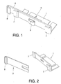
- the device for connecting elevator apparatus guides proposed by the invention, in which said elevator apparatus comprises two guides (3) extending in substantially parallel courses, the bases (4) thereof having a substantially coplanar arrangement, comprises a first part (1) configured to prevent a movement of said two guides (3) in a first direction according to a first course perpendicular to the guides (3) and contained in the plane of the bases (4) thereof, allowing a movement of the guides (3) according to the longitudinal directions thereof.
- the device comprises a second part (2) configured to prevent a movement of at least one guide (3) in a second direction, opposite to the first direction, according to the first course, likewise allowing its movement according to its longitudinal course.
- connection means (5) configured to fix the relative position between said first part (1) and said second part (2), for which said connection means (5) comprise a threaded element (5') and a tightening element (5").
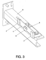
- the first part (1) and the second part (2) are integral with a support element (6) which is fixed to an elevator shaft, preventing a movement of the guides (3) according to any course contained in a plane perpendicular to the course of said guides (3).
- the invention allows a saving in time for positioning the guides (3), since they are quickly positioned by taking each guide (3) against the corresponding surface in the parts (1, 2).
- the first part (1) and the second part (2) comprise flanges (7, 8) which are configured to secure the bases (4) of at least two guides (3) by their flanks (4').
- the flanges (7, 8) in which the guides (3) are inserted undergo an elastic deformation generating pressure in the guide (3) to be able to secure it, although the invention contemplates any other equivalent securing means.
- the steel of these parts will preferably be sheets with a thickness comprised between 1 and 10 mm of UHSS steel, i.e., steel with a high elastic limit, suitably folded, which allows generating a higher pressure in the guide (3).
- the second part (2) comprises a flange (8) integrated in said second part (2), the device comprising a bracket (9) which is integral with the connection means (5) and is configured to be oriented according to the course of said flange (8).
- the first part (1) comprises two flanges (7) which are oriented in the same course and integrated in said first part (1).
- the flanges (7) of the first part (1) are oriented according to the first direction of the course perpendicular to each guide (3) and contained in the plane of the respective bases (4) thereof, and the flange (8) of the second part (2) and the bracket (9) are oriented according to the second direction of said courses.
- a second aspect of the invention relates to an elevator apparatus comprising at least one device for connecting guides (3) such as the one described previously, comprising at least one traction unit which is located inside an elevator shaft, said traction unit being at least partially supported by at least one guide (3).
- the elevator apparatus of the invention comprises at least one car configured to move in an elevator shaft, said car being guided by a first pair of guides, and at least one counterweight guided by a second pair of guides, such that the device for connecting guides is configured to brace least one guide of the first pair of guides with at least one guide of the second pair of guides.
- a third aspect of the invention relates to a method for assembling guides in an elevator apparatus, comprising using at least one device for connecting guides such as the one described previously, in which said method comprises the following steps:
Landscapes
- Cage And Drive Apparatuses For Elevators (AREA)
- Lift-Guide Devices, And Elevator Ropes And Cables (AREA)
Applications Claiming Priority (1)
| Application Number | Priority Date | Filing Date | Title |
|---|---|---|---|
| ES200802867A ES2341071B1 (es) | 2008-10-09 | 2008-10-09 | Dispositivo para unir guias de aparatos elevadores, aparato elevador que comprende dicho dispositivo y metodo para montar guias de aparatoselevadores. |
Publications (2)
| Publication Number | Publication Date |
|---|---|
| EP2174902A1 true EP2174902A1 (de) | 2010-04-14 |
| EP2174902B1 EP2174902B1 (de) | 2016-06-01 |
Family
ID=41467901
Family Applications (1)
| Application Number | Title | Priority Date | Filing Date |
|---|---|---|---|
| EP09382196.5A Not-in-force EP2174902B1 (de) | 2008-10-09 | 2009-10-05 | Führung für Aufzugsschienen |
Country Status (2)
| Country | Link |
|---|---|
| EP (1) | EP2174902B1 (de) |
| ES (2) | ES2341071B1 (de) |
Cited By (3)
| Publication number | Priority date | Publication date | Assignee | Title |
|---|---|---|---|---|
| FR2996216A1 (fr) * | 2012-10-03 | 2014-04-04 | Sodimas | Fixation d'un guide d'ascenseur a une paroi |
| WO2017103017A1 (de) * | 2015-12-17 | 2017-06-22 | Inventio Ag | Befestigungsmodul zum befestigen von aufzugsschienen |
| DE102021109086A1 (de) | 2021-04-12 | 2022-10-13 | Fritz Kübler GmbH | Befestigungsbausatz für ein Aufzugspositionsinformationssystem |
Families Citing this family (1)
| Publication number | Priority date | Publication date | Assignee | Title |
|---|---|---|---|---|
| ES2446841B1 (es) * | 2012-09-07 | 2015-03-31 | S.A. De Vera (Savera) | Sistema de brida integrada para fijación de guías de ascensor a una estructura fija |
Citations (5)
| Publication number | Priority date | Publication date | Assignee | Title |
|---|---|---|---|---|
| DE553322C (de) * | 1929-07-30 | 1932-06-24 | Otis Aufzugswerke G M B H | Fuehrung fuer senkrecht bewegliche Aufzugfahrkoerbe |
| JPH01271385A (ja) * | 1988-04-21 | 1989-10-30 | Toshiba Corp | ガイドレール固定装置 |
| EP0643007A2 (de) * | 1993-09-10 | 1995-03-15 | Kone Oy | Verfahren zum Befestigen von Leitschienen |
| US20030168291A1 (en) * | 2002-03-06 | 2003-09-11 | Sneed Terryle L. | Connector brackets |
| JP2005272077A (ja) * | 2004-03-24 | 2005-10-06 | Mitsubishi Electric Corp | 免震建物用エレベーター装置 |
Family Cites Families (3)
| Publication number | Priority date | Publication date | Assignee | Title |
|---|---|---|---|---|
| US7234566B2 (en) * | 2003-09-15 | 2007-06-26 | The Vertical Solutions Company, Inc. | Elevator insert |
| KR100960439B1 (ko) * | 2006-03-22 | 2010-05-28 | 미쓰비시덴키 가부시키가이샤 | 엘리베이터용 가이드 레일의 지지장치 |
| DE102008016140A1 (de) * | 2008-03-28 | 2009-11-05 | Riedl Aufzugbau Gmbh & Co. Kg | Schienenabstandhalter und Schienenhaltebügel zum Halten von Führungsschienen und Gegengewichten eines Aufzugs |
-
2008
- 2008-10-09 ES ES200802867A patent/ES2341071B1/es not_active Expired - Fee Related
-
2009
- 2009-10-05 EP EP09382196.5A patent/EP2174902B1/de not_active Not-in-force
- 2009-10-05 ES ES09382196.5T patent/ES2587746T3/es active Active
Patent Citations (5)
| Publication number | Priority date | Publication date | Assignee | Title |
|---|---|---|---|---|
| DE553322C (de) * | 1929-07-30 | 1932-06-24 | Otis Aufzugswerke G M B H | Fuehrung fuer senkrecht bewegliche Aufzugfahrkoerbe |
| JPH01271385A (ja) * | 1988-04-21 | 1989-10-30 | Toshiba Corp | ガイドレール固定装置 |
| EP0643007A2 (de) * | 1993-09-10 | 1995-03-15 | Kone Oy | Verfahren zum Befestigen von Leitschienen |
| US20030168291A1 (en) * | 2002-03-06 | 2003-09-11 | Sneed Terryle L. | Connector brackets |
| JP2005272077A (ja) * | 2004-03-24 | 2005-10-06 | Mitsubishi Electric Corp | 免震建物用エレベーター装置 |
Cited By (7)
| Publication number | Priority date | Publication date | Assignee | Title |
|---|---|---|---|---|
| FR2996216A1 (fr) * | 2012-10-03 | 2014-04-04 | Sodimas | Fixation d'un guide d'ascenseur a une paroi |
| WO2017103017A1 (de) * | 2015-12-17 | 2017-06-22 | Inventio Ag | Befestigungsmodul zum befestigen von aufzugsschienen |
| CN108698794A (zh) * | 2015-12-17 | 2018-10-23 | 因温特奥股份公司 | 用于固定电梯轨的固定模块 |
| AU2016372444B2 (en) * | 2015-12-17 | 2019-09-19 | Inventio Ag | Fastening module for fastening elevator rails |
| CN108698794B (zh) * | 2015-12-17 | 2020-02-21 | 因温特奥股份公司 | 用于固定电梯轨的固定模块 |
| US11180345B2 (en) | 2015-12-17 | 2021-11-23 | Inventio Ag | Fastening module for fastening elevator rails |
| DE102021109086A1 (de) | 2021-04-12 | 2022-10-13 | Fritz Kübler GmbH | Befestigungsbausatz für ein Aufzugspositionsinformationssystem |
Also Published As
| Publication number | Publication date |
|---|---|
| EP2174902B1 (de) | 2016-06-01 |
| ES2341071B1 (es) | 2011-06-06 |
| ES2587746T3 (es) | 2016-10-26 |
| ES2341071A1 (es) | 2010-06-14 |
Similar Documents
| Publication | Publication Date | Title |
|---|---|---|
| EP2595909B1 (de) | Montagebauteile in einem aufzug | |
| JP5289664B2 (ja) | エレベータガイドレール取付アセンブリ | |
| CN101146732B (zh) | 电梯用导轨的支承装置 | |
| JP2004277175A (ja) | エレベータカウンターウエイト | |
| US10519006B2 (en) | Elevator guide rail bracket and method for securing a guide rail | |
| EP2174902A1 (de) | Führung für Aufzugsschienen | |
| US8302740B2 (en) | Integrated support for elevator machine, sheaves and terminations | |
| CN112408150B (zh) | 导轨支架组件 | |
| US6672013B1 (en) | Method of installing elevator rails | |
| JP2007523022A (ja) | エレベータレール支持ブラケット | |
| JP2023519577A (ja) | エレベータシステムのレールビークル用のユニバーサルコンソールおよびピットアセンブリ、レールシステム、ならびにレールシステムを位置合わせするための方法 | |
| JPWO2009050807A1 (ja) | エレベータかご及びその据付方法 | |
| US5119908A (en) | Procedure for mounting the guide rails for an elevator car or counterweight, and a mounting system implementing the procedure | |
| ES2526680T3 (es) | Interfaz de medios de suspensión y de tracción para ascensores | |
| US5131505A (en) | Guide rail system for elevators | |
| US20040096266A1 (en) | Connecting element for an assembly system | |
| US6595331B2 (en) | Bracket for securing elevator components | |
| JP4541732B2 (ja) | カウンタウエイト枠広がり防止装置 | |
| JP7530270B2 (ja) | タワークレーンの設置構造 | |
| JP7593767B2 (ja) | エレベーター用巻上機およびエレベーター用巻上機の設置方法 | |
| JP2012136306A (ja) | エレベータのかご上手摺装置 | |
| EP4349759A1 (de) | Aufzugsanordnung mit führungsschienenbefestigungshalterungseinheiten sowie befestigungshalterungseinheit dafür | |
| JP2006036450A (ja) | エレベータ装置 | |
| JP2009275418A (ja) | 縦壁パネルの取付け構造およびベース金具 | |
| JP2007062949A (ja) | ガイドレール支持構造およびガイドレール支持方法 |
Legal Events
| Date | Code | Title | Description |
|---|---|---|---|
| PUAI | Public reference made under article 153(3) epc to a published international application that has entered the european phase |
Free format text: ORIGINAL CODE: 0009012 |
|
| AK | Designated contracting states |
Kind code of ref document: A1 Designated state(s): AT BE BG CH CY CZ DE DK EE ES FI FR GB GR HR HU IE IS IT LI LT LU LV MC MK MT NL NO PL PT RO SE SI SK SM TR |
|
| 17P | Request for examination filed |
Effective date: 20101014 |
|
| GRAP | Despatch of communication of intention to grant a patent |
Free format text: ORIGINAL CODE: EPIDOSNIGR1 |
|
| INTG | Intention to grant announced |
Effective date: 20151223 |
|
| RIN1 | Information on inventor provided before grant (corrected) |
Inventor name: SANTIAGO, ESTEBAN Inventor name: ELIZEGI XABIER Inventor name: LAPLACE, IBON Inventor name: ZUGAZAGA, DANIEL |
|
| GRAS | Grant fee paid |
Free format text: ORIGINAL CODE: EPIDOSNIGR3 |
|
| GRAA | (expected) grant |
Free format text: ORIGINAL CODE: 0009210 |
|
| AK | Designated contracting states |
Kind code of ref document: B1 Designated state(s): AT BE BG CH CY CZ DE DK EE ES FI FR GB GR HR HU IE IS IT LI LT LU LV MC MK MT NL NO PL PT RO SE SI SK SM TR |
|
| REG | Reference to a national code |
Ref country code: GB Ref legal event code: FG4D |
|
| REG | Reference to a national code |
Ref country code: CH Ref legal event code: EP Ref country code: AT Ref legal event code: REF Ref document number: 803762 Country of ref document: AT Kind code of ref document: T Effective date: 20160615 |
|
| REG | Reference to a national code |
Ref country code: IE Ref legal event code: FG4D |
|
| REG | Reference to a national code |
Ref country code: DE Ref legal event code: R096 Ref document number: 602009038995 Country of ref document: DE |
|
| REG | Reference to a national code |
Ref country code: LT Ref legal event code: MG4D |
|
| REG | Reference to a national code |
Ref country code: NL Ref legal event code: MP Effective date: 20160601 |
|
| REG | Reference to a national code |
Ref country code: FR Ref legal event code: PLFP Year of fee payment: 8 |
|
| REG | Reference to a national code |
Ref country code: ES Ref legal event code: FG2A Ref document number: 2587746 Country of ref document: ES Kind code of ref document: T3 Effective date: 20161026 |
|
| PG25 | Lapsed in a contracting state [announced via postgrant information from national office to epo] |
Ref country code: LT Free format text: LAPSE BECAUSE OF FAILURE TO SUBMIT A TRANSLATION OF THE DESCRIPTION OR TO PAY THE FEE WITHIN THE PRESCRIBED TIME-LIMIT Effective date: 20160601 Ref country code: FI Free format text: LAPSE BECAUSE OF FAILURE TO SUBMIT A TRANSLATION OF THE DESCRIPTION OR TO PAY THE FEE WITHIN THE PRESCRIBED TIME-LIMIT Effective date: 20160601 Ref country code: NO Free format text: LAPSE BECAUSE OF FAILURE TO SUBMIT A TRANSLATION OF THE DESCRIPTION OR TO PAY THE FEE WITHIN THE PRESCRIBED TIME-LIMIT Effective date: 20160901 |
|
| REG | Reference to a national code |
Ref country code: AT Ref legal event code: MK05 Ref document number: 803762 Country of ref document: AT Kind code of ref document: T Effective date: 20160601 |
|
| PG25 | Lapsed in a contracting state [announced via postgrant information from national office to epo] |
Ref country code: SE Free format text: LAPSE BECAUSE OF FAILURE TO SUBMIT A TRANSLATION OF THE DESCRIPTION OR TO PAY THE FEE WITHIN THE PRESCRIBED TIME-LIMIT Effective date: 20160601 Ref country code: GR Free format text: LAPSE BECAUSE OF FAILURE TO SUBMIT A TRANSLATION OF THE DESCRIPTION OR TO PAY THE FEE WITHIN THE PRESCRIBED TIME-LIMIT Effective date: 20160902 Ref country code: LV Free format text: LAPSE BECAUSE OF FAILURE TO SUBMIT A TRANSLATION OF THE DESCRIPTION OR TO PAY THE FEE WITHIN THE PRESCRIBED TIME-LIMIT Effective date: 20160601 Ref country code: NL Free format text: LAPSE BECAUSE OF FAILURE TO SUBMIT A TRANSLATION OF THE DESCRIPTION OR TO PAY THE FEE WITHIN THE PRESCRIBED TIME-LIMIT Effective date: 20160601 Ref country code: HR Free format text: LAPSE BECAUSE OF FAILURE TO SUBMIT A TRANSLATION OF THE DESCRIPTION OR TO PAY THE FEE WITHIN THE PRESCRIBED TIME-LIMIT Effective date: 20160601 |
|
| PG25 | Lapsed in a contracting state [announced via postgrant information from national office to epo] |
Ref country code: RO Free format text: LAPSE BECAUSE OF FAILURE TO SUBMIT A TRANSLATION OF THE DESCRIPTION OR TO PAY THE FEE WITHIN THE PRESCRIBED TIME-LIMIT Effective date: 20160601 Ref country code: CZ Free format text: LAPSE BECAUSE OF FAILURE TO SUBMIT A TRANSLATION OF THE DESCRIPTION OR TO PAY THE FEE WITHIN THE PRESCRIBED TIME-LIMIT Effective date: 20160601 Ref country code: EE Free format text: LAPSE BECAUSE OF FAILURE TO SUBMIT A TRANSLATION OF THE DESCRIPTION OR TO PAY THE FEE WITHIN THE PRESCRIBED TIME-LIMIT Effective date: 20160601 Ref country code: SK Free format text: LAPSE BECAUSE OF FAILURE TO SUBMIT A TRANSLATION OF THE DESCRIPTION OR TO PAY THE FEE WITHIN THE PRESCRIBED TIME-LIMIT Effective date: 20160601 Ref country code: IS Free format text: LAPSE BECAUSE OF FAILURE TO SUBMIT A TRANSLATION OF THE DESCRIPTION OR TO PAY THE FEE WITHIN THE PRESCRIBED TIME-LIMIT Effective date: 20161001 |
|
| PG25 | Lapsed in a contracting state [announced via postgrant information from national office to epo] |
Ref country code: SM Free format text: LAPSE BECAUSE OF FAILURE TO SUBMIT A TRANSLATION OF THE DESCRIPTION OR TO PAY THE FEE WITHIN THE PRESCRIBED TIME-LIMIT Effective date: 20160601 Ref country code: PT Free format text: LAPSE BECAUSE OF FAILURE TO SUBMIT A TRANSLATION OF THE DESCRIPTION OR TO PAY THE FEE WITHIN THE PRESCRIBED TIME-LIMIT Effective date: 20161003 Ref country code: AT Free format text: LAPSE BECAUSE OF FAILURE TO SUBMIT A TRANSLATION OF THE DESCRIPTION OR TO PAY THE FEE WITHIN THE PRESCRIBED TIME-LIMIT Effective date: 20160601 Ref country code: BE Free format text: LAPSE BECAUSE OF NON-PAYMENT OF DUE FEES Effective date: 20160601 Ref country code: PL Free format text: LAPSE BECAUSE OF FAILURE TO SUBMIT A TRANSLATION OF THE DESCRIPTION OR TO PAY THE FEE WITHIN THE PRESCRIBED TIME-LIMIT Effective date: 20160601 |
|
| REG | Reference to a national code |
Ref country code: DE Ref legal event code: R097 Ref document number: 602009038995 Country of ref document: DE |
|
| PLBE | No opposition filed within time limit |
Free format text: ORIGINAL CODE: 0009261 |
|
| STAA | Information on the status of an ep patent application or granted ep patent |
Free format text: STATUS: NO OPPOSITION FILED WITHIN TIME LIMIT |
|
| 26N | No opposition filed |
Effective date: 20170302 |
|
| PG25 | Lapsed in a contracting state [announced via postgrant information from national office to epo] |
Ref country code: DK Free format text: LAPSE BECAUSE OF FAILURE TO SUBMIT A TRANSLATION OF THE DESCRIPTION OR TO PAY THE FEE WITHIN THE PRESCRIBED TIME-LIMIT Effective date: 20160601 Ref country code: SI Free format text: LAPSE BECAUSE OF FAILURE TO SUBMIT A TRANSLATION OF THE DESCRIPTION OR TO PAY THE FEE WITHIN THE PRESCRIBED TIME-LIMIT Effective date: 20160601 |
|
| REG | Reference to a national code |
Ref country code: CH Ref legal event code: PL |
|
| REG | Reference to a national code |
Ref country code: IE Ref legal event code: MM4A |
|
| PG25 | Lapsed in a contracting state [announced via postgrant information from national office to epo] |
Ref country code: CH Free format text: LAPSE BECAUSE OF NON-PAYMENT OF DUE FEES Effective date: 20161031 Ref country code: LI Free format text: LAPSE BECAUSE OF NON-PAYMENT OF DUE FEES Effective date: 20161031 |
|
| PG25 | Lapsed in a contracting state [announced via postgrant information from national office to epo] |
Ref country code: LU Free format text: LAPSE BECAUSE OF NON-PAYMENT OF DUE FEES Effective date: 20161005 |
|
| REG | Reference to a national code |
Ref country code: FR Ref legal event code: PLFP Year of fee payment: 9 |
|
| PG25 | Lapsed in a contracting state [announced via postgrant information from national office to epo] |
Ref country code: IE Free format text: LAPSE BECAUSE OF NON-PAYMENT OF DUE FEES Effective date: 20161005 |
|
| PG25 | Lapsed in a contracting state [announced via postgrant information from national office to epo] |
Ref country code: HU Free format text: LAPSE BECAUSE OF FAILURE TO SUBMIT A TRANSLATION OF THE DESCRIPTION OR TO PAY THE FEE WITHIN THE PRESCRIBED TIME-LIMIT; INVALID AB INITIO Effective date: 20091005 Ref country code: CY Free format text: LAPSE BECAUSE OF FAILURE TO SUBMIT A TRANSLATION OF THE DESCRIPTION OR TO PAY THE FEE WITHIN THE PRESCRIBED TIME-LIMIT Effective date: 20160601 |
|
| PG25 | Lapsed in a contracting state [announced via postgrant information from national office to epo] |
Ref country code: MK Free format text: LAPSE BECAUSE OF FAILURE TO SUBMIT A TRANSLATION OF THE DESCRIPTION OR TO PAY THE FEE WITHIN THE PRESCRIBED TIME-LIMIT Effective date: 20160601 Ref country code: MT Free format text: LAPSE BECAUSE OF NON-PAYMENT OF DUE FEES Effective date: 20161031 Ref country code: MC Free format text: LAPSE BECAUSE OF FAILURE TO SUBMIT A TRANSLATION OF THE DESCRIPTION OR TO PAY THE FEE WITHIN THE PRESCRIBED TIME-LIMIT Effective date: 20160601 |
|
| PG25 | Lapsed in a contracting state [announced via postgrant information from national office to epo] |
Ref country code: BG Free format text: LAPSE BECAUSE OF FAILURE TO SUBMIT A TRANSLATION OF THE DESCRIPTION OR TO PAY THE FEE WITHIN THE PRESCRIBED TIME-LIMIT Effective date: 20160601 |
|
| REG | Reference to a national code |
Ref country code: FR Ref legal event code: PLFP Year of fee payment: 10 |
|
| PGFP | Annual fee paid to national office [announced via postgrant information from national office to epo] |
Ref country code: TR Payment date: 20201008 Year of fee payment: 12 |
|
| PGFP | Annual fee paid to national office [announced via postgrant information from national office to epo] |
Ref country code: FR Payment date: 20220922 Year of fee payment: 14 |
|
| PGFP | Annual fee paid to national office [announced via postgrant information from national office to epo] |
Ref country code: IT Payment date: 20221026 Year of fee payment: 14 Ref country code: GB Payment date: 20221020 Year of fee payment: 14 Ref country code: ES Payment date: 20221107 Year of fee payment: 14 Ref country code: DE Payment date: 20221019 Year of fee payment: 14 |
|
| P01 | Opt-out of the competence of the unified patent court (upc) registered |
Effective date: 20230604 |
|
| REG | Reference to a national code |
Ref country code: DE Ref legal event code: R119 Ref document number: 602009038995 Country of ref document: DE |
|
| GBPC | Gb: european patent ceased through non-payment of renewal fee |
Effective date: 20231005 |
|
| PG25 | Lapsed in a contracting state [announced via postgrant information from national office to epo] |
Ref country code: GB Free format text: LAPSE BECAUSE OF NON-PAYMENT OF DUE FEES Effective date: 20231005 |
|
| PG25 | Lapsed in a contracting state [announced via postgrant information from national office to epo] |
Ref country code: GB Free format text: LAPSE BECAUSE OF NON-PAYMENT OF DUE FEES Effective date: 20231005 Ref country code: FR Free format text: LAPSE BECAUSE OF NON-PAYMENT OF DUE FEES Effective date: 20231031 Ref country code: DE Free format text: LAPSE BECAUSE OF NON-PAYMENT OF DUE FEES Effective date: 20240501 |
|
| PG25 | Lapsed in a contracting state [announced via postgrant information from national office to epo] |
Ref country code: TR Free format text: LAPSE BECAUSE OF NON-PAYMENT OF DUE FEES Effective date: 20211005 |
|
| REG | Reference to a national code |
Ref country code: ES Ref legal event code: FD2A Effective date: 20241126 |
|
| PG25 | Lapsed in a contracting state [announced via postgrant information from national office to epo] |
Ref country code: IT Free format text: LAPSE BECAUSE OF NON-PAYMENT OF DUE FEES Effective date: 20231005 |
|
| PG25 | Lapsed in a contracting state [announced via postgrant information from national office to epo] |
Ref country code: IT Free format text: LAPSE BECAUSE OF NON-PAYMENT OF DUE FEES Effective date: 20231005 |
|
| PG25 | Lapsed in a contracting state [announced via postgrant information from national office to epo] |
Ref country code: ES Free format text: LAPSE BECAUSE OF NON-PAYMENT OF DUE FEES Effective date: 20231006 |
|
| PG25 | Lapsed in a contracting state [announced via postgrant information from national office to epo] |
Ref country code: ES Free format text: LAPSE BECAUSE OF NON-PAYMENT OF DUE FEES Effective date: 20231006 |