EP2174001B1 - Machine hydraulique comprenant des moyens d'injection d'un écoulement prélevé d'un écoulement principal - Google Patents
Machine hydraulique comprenant des moyens d'injection d'un écoulement prélevé d'un écoulement principal Download PDFInfo
- Publication number
- EP2174001B1 EP2174001B1 EP08826872.7A EP08826872A EP2174001B1 EP 2174001 B1 EP2174001 B1 EP 2174001B1 EP 08826872 A EP08826872 A EP 08826872A EP 2174001 B1 EP2174001 B1 EP 2174001B1
- Authority
- EP
- European Patent Office
- Prior art keywords
- flow
- blades
- vicinity
- hydraulic machine
- ceiling
- Prior art date
- Legal status (The legal status is an assumption and is not a legal conclusion. Google has not performed a legal analysis and makes no representation as to the accuracy of the status listed.)
- Not-in-force
Links
- 238000011144 upstream manufacturing Methods 0.000 claims description 18
- XLYOFNOQVPJJNP-UHFFFAOYSA-N water Substances O XLYOFNOQVPJJNP-UHFFFAOYSA-N 0.000 claims description 5
- 238000002347 injection Methods 0.000 description 10
- 239000007924 injection Substances 0.000 description 10
- 230000015572 biosynthetic process Effects 0.000 description 9
- 241000287107 Passer Species 0.000 description 1
- 230000000694 effects Effects 0.000 description 1
- 235000021183 entrée Nutrition 0.000 description 1
- 239000000203 mixture Substances 0.000 description 1
- 230000004048 modification Effects 0.000 description 1
- 238000012986 modification Methods 0.000 description 1
Images
Classifications
-
- F—MECHANICAL ENGINEERING; LIGHTING; HEATING; WEAPONS; BLASTING
- F03—MACHINES OR ENGINES FOR LIQUIDS; WIND, SPRING, OR WEIGHT MOTORS; PRODUCING MECHANICAL POWER OR A REACTIVE PROPULSIVE THRUST, NOT OTHERWISE PROVIDED FOR
- F03B—MACHINES OR ENGINES FOR LIQUIDS
- F03B11/00—Parts or details not provided for in, or of interest apart from, the preceding groups, e.g. wear-protection couplings, between turbine and generator
- F03B11/04—Parts or details not provided for in, or of interest apart from, the preceding groups, e.g. wear-protection couplings, between turbine and generator for diminishing cavitation or vibration, e.g. balancing
-
- F—MECHANICAL ENGINEERING; LIGHTING; HEATING; WEAPONS; BLASTING
- F03—MACHINES OR ENGINES FOR LIQUIDS; WIND, SPRING, OR WEIGHT MOTORS; PRODUCING MECHANICAL POWER OR A REACTIVE PROPULSIVE THRUST, NOT OTHERWISE PROVIDED FOR
- F03B—MACHINES OR ENGINES FOR LIQUIDS
- F03B1/00—Engines of impulse type, i.e. turbines with jets of high-velocity liquid impinging on blades or like rotors, e.g. Pelton wheels; Parts or details peculiar thereto
- F03B1/04—Nozzles; Nozzle-carrying members
-
- F—MECHANICAL ENGINEERING; LIGHTING; HEATING; WEAPONS; BLASTING
- F03—MACHINES OR ENGINES FOR LIQUIDS; WIND, SPRING, OR WEIGHT MOTORS; PRODUCING MECHANICAL POWER OR A REACTIVE PROPULSIVE THRUST, NOT OTHERWISE PROVIDED FOR
- F03B—MACHINES OR ENGINES FOR LIQUIDS
- F03B11/00—Parts or details not provided for in, or of interest apart from, the preceding groups, e.g. wear-protection couplings, between turbine and generator
- F03B11/002—Injecting air or other fluid
-
- F—MECHANICAL ENGINEERING; LIGHTING; HEATING; WEAPONS; BLASTING
- F03—MACHINES OR ENGINES FOR LIQUIDS; WIND, SPRING, OR WEIGHT MOTORS; PRODUCING MECHANICAL POWER OR A REACTIVE PROPULSIVE THRUST, NOT OTHERWISE PROVIDED FOR
- F03B—MACHINES OR ENGINES FOR LIQUIDS
- F03B3/00—Machines or engines of reaction type; Parts or details peculiar thereto
- F03B3/12—Blades; Blade-carrying rotors
- F03B3/125—Rotors for radial flow at high-pressure side and axial flow at low-pressure side, e.g. for Francis-type turbines
-
- Y—GENERAL TAGGING OF NEW TECHNOLOGICAL DEVELOPMENTS; GENERAL TAGGING OF CROSS-SECTIONAL TECHNOLOGIES SPANNING OVER SEVERAL SECTIONS OF THE IPC; TECHNICAL SUBJECTS COVERED BY FORMER USPC CROSS-REFERENCE ART COLLECTIONS [XRACs] AND DIGESTS
- Y02—TECHNOLOGIES OR APPLICATIONS FOR MITIGATION OR ADAPTATION AGAINST CLIMATE CHANGE
- Y02E—REDUCTION OF GREENHOUSE GAS [GHG] EMISSIONS, RELATED TO ENERGY GENERATION, TRANSMISSION OR DISTRIBUTION
- Y02E10/00—Energy generation through renewable energy sources
- Y02E10/20—Hydro energy
Definitions
- the present invention relates to a Francis hydraulic machine of the type traversed by a main flow of water, comprising a wheel of a turbine, in the vicinity of which is formed at least one vortex zone or a reduced pressure zone or a cavitation zone , the wheel being comprising blades arranged between a ceiling and a belt, the machine comprising means for injecting a flow taken from said main flow, unmodified with respect to the main flow, into said vortex or reduced pressure zone or cavitation so as to locally modify the main flow or increase the pressure in this zone.
- Such a machine is used, for example in a hydroelectric power plant.
- the machine is installed on the water or is supplied with water from a tank into which flows one or more streams.
- the document US-1 942 995 describes a hydraulic machine of the aforementioned type, for injecting a flow taken from the main flow in the cavitation zone formed along the vanes of the impeller wheel.
- One of the aims of the invention is to overcome these disadvantages by proposing a hydraulic machine to remove, in a simple way, both vortex zones, reduced pressure and cavitation.
- the invention relates to a hydraulic machine of the aforementioned type, wherein said means injecting the flow taken from the ceiling or from the belt by means of openings in said ceiling or said belt.
- the invention described below applies to hydraulic machines of the Francis turbine type. As this machine is known, it is not described in detail in the present description. The invention is also applicable to other types of hydraulic machines in which problems of formation of vortex zones, reduced pressure or cavitation arise.
- upstream and downstream are defined with respect to the direction of flow of the main flow E through the hydraulic machine.
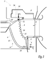
- a Francis 2 turbine comprising a wheel 4 comprising vanes 6 arranged between a ceiling 28 and a belt 30.
- dawn 6, represented on the Fig. 1 comprises ducts (not shown) extending inside the blade between an inlet opening 22 and an outlet opening 24, 26.
- the inlet openings 22 of the ducts are disposed in the vicinity of the duct. upstream end 8 of the blade 6 so as to take a flow of the main flow E upstream of the blade.
- the outlet openings 24, 26 of the pipes are arranged to inject the flow taken from the side walls of the vanes 6 in the vicinity of the upstream end 8 and / or the downstream end 10 of the vane 6.
- the flow taken and injected has the effect of locally modifying the main flow E and thus avoid the formation of cavitation phenomena on the blades profile.
- Some pipes thus comprise an outlet opening 24 opening into a side wall of the blade 6 in the vicinity of the upstream end 8 in order to avoid cavitation formation phenomena on the blades in the vicinity of the upstream end 8.
- Other pipes comprise an outlet opening 26 opening into a side wall of the blade 6 in the vicinity of the downstream end 10 so as to avoid the phenomena of cavitation formation on the blades in the vicinity of the upstream end 10.
- the inlet and outlet openings may be arranged in series along the upstream end 8 and the downstream end 10 of the blade 6 in a direction that may be perpendicular to the direction of the main flow E, as represented by the outlet openings 24 of the Fig. 1 .
- outlet openings are arranged so as to open into the downstream end 10 of the blade 6 in the direction of the main flow E.
- the injection of the flow taken from the downstream end allows to remove the swirling zone which is formed in the wake of the blades 6.
- the flow taken is for example injected into the base of the downstream end 10 of the blade 6.
- the blades 6 of the wheel 4 are arranged between a ceiling 28 and a belt 30.
- These openings 31 communicate with the outlet openings 24 and 26 and with the outlet openings opening into the downstream end 10 by means of pipes not shown.
- the flow E 2 is taken from the main flow E supplying the turbine Francis 2 upstream of the vanes 6.
- the drawn flow E 2 passing between the fixed part and the blades of the turbine 2 and then passing into a space ring 34 located above the ceiling 28, may for example be brought by means of pipes not shown. This flow E 2 passes through the openings 31 and is guided towards the outlet openings 24, 26.
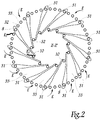
- the flow E 2 taken from the annular space 34 passes through the openings 32 and supplies the spaces 33 between the vanes 6, as shown in FIGS. Fig. 1 and 2 .
- the openings 32 are distributed in the ceiling 28 facing the spaces 33 separating the blades 6.
- the flow taken E 2 is injected between the blades 6 and modifies the properties of the flow E to avoid formation phenomena vortex between the blades 6.
- the withdrawn flow E 2 can pass through the belt 30 by means of openings (not shown) formed therein.
- the openings 31, 32 formed in the ceiling 28 and / or the belt 30 thus make it possible to overcome in a simple manner both the problems of formation of cavitation zones on the blades, vortex-forming zones between the blades and vortices. downstream of the blades.
- the injection means comprise a valve 72 disposed in the path of the withdrawn flow, as shown in FIG. Fig 1 .
- the valve 72 is movable between an open position in which it passes the withdrawn flow and a closed position in which it prevents the flow of the withdrawn flow.
- the valve 72 is for example disposed in the vicinity of each inlet opening of the injection means and allows to control manually or automatically injection of the withdrawn flow. In the case of the Francis turbine, the valve 72 is provided in the vicinity of each opening 32 formed in the ceiling 28.
- valve 72 The movement of the valve 72 is controlled by control means (not shown), mechanical or electrical in a manner known per se.
- control means not shown
- an operator or operator of the machine puts the valve or valves in the open position which allows to inject the flow taken from said zones and to prevent the formation of these zones, as described above.
Landscapes
- Engineering & Computer Science (AREA)
- Chemical & Material Sciences (AREA)
- Combustion & Propulsion (AREA)
- Mechanical Engineering (AREA)
- General Engineering & Computer Science (AREA)
- Hydraulic Turbines (AREA)
- Structures Of Non-Positive Displacement Pumps (AREA)
- Control Of Water Turbines (AREA)
- Details Of Valves (AREA)
Applications Claiming Priority (2)
| Application Number | Priority Date | Filing Date | Title |
|---|---|---|---|
| FR0705332A FR2919353B1 (fr) | 2007-07-23 | 2007-07-23 | Machine hydraulique comprenant des moyens d'injection d'un ecoulement preleve d'un ecoulement principal |
| PCT/FR2008/051384 WO2009016314A2 (fr) | 2007-07-23 | 2008-07-23 | Machine hydraulique comprenant des moyens d'injection d'un écoulement prélevé d'un écoulement principal |
Publications (2)
| Publication Number | Publication Date |
|---|---|
| EP2174001A2 EP2174001A2 (fr) | 2010-04-14 |
| EP2174001B1 true EP2174001B1 (fr) | 2016-12-14 |
Family
ID=39310993
Family Applications (3)
| Application Number | Title | Priority Date | Filing Date |
|---|---|---|---|
| EP08826872.7A Not-in-force EP2174001B1 (fr) | 2007-07-23 | 2008-07-23 | Machine hydraulique comprenant des moyens d'injection d'un écoulement prélevé d'un écoulement principal |
| EP08826706.7A Not-in-force EP2174000B1 (fr) | 2007-07-23 | 2008-07-23 | Machine hydraulique de type pelton comprenant des moyens d'injection d'un écoulement prélevé d'un écoulement principal |
| EP08826846A Not-in-force EP2171261B1 (fr) | 2007-07-23 | 2008-07-23 | Machine hydraulique comprenant des moyens d'injection d'un écoulement prélevé d'un écoulement principal |
Family Applications After (2)
| Application Number | Title | Priority Date | Filing Date |
|---|---|---|---|
| EP08826706.7A Not-in-force EP2174000B1 (fr) | 2007-07-23 | 2008-07-23 | Machine hydraulique de type pelton comprenant des moyens d'injection d'un écoulement prélevé d'un écoulement principal |
| EP08826846A Not-in-force EP2171261B1 (fr) | 2007-07-23 | 2008-07-23 | Machine hydraulique comprenant des moyens d'injection d'un écoulement prélevé d'un écoulement principal |
Country Status (16)
| Country | Link |
|---|---|
| US (3) | US8491269B2 (OSRAM) |
| EP (3) | EP2174001B1 (OSRAM) |
| JP (3) | JP5460591B2 (OSRAM) |
| KR (3) | KR101456430B1 (OSRAM) |
| CN (3) | CN101755121B (OSRAM) |
| AU (3) | AU2008281600B2 (OSRAM) |
| BR (3) | BRPI0814565B1 (OSRAM) |
| CA (3) | CA2694073C (OSRAM) |
| EC (3) | ECSP109892A (OSRAM) |
| ES (1) | ES2399773T3 (OSRAM) |
| FR (1) | FR2919353B1 (OSRAM) |
| MX (3) | MX2010000911A (OSRAM) |
| MY (3) | MY151301A (OSRAM) |
| PT (1) | PT2171261E (OSRAM) |
| SI (1) | SI2171261T1 (OSRAM) |
| WO (3) | WO2009016316A2 (OSRAM) |
Families Citing this family (15)
| Publication number | Priority date | Publication date | Assignee | Title |
|---|---|---|---|---|
| FR2919353B1 (fr) * | 2007-07-23 | 2014-02-14 | Alstom Power Hydraulique | Machine hydraulique comprenant des moyens d'injection d'un ecoulement preleve d'un ecoulement principal |
| FR2953565B1 (fr) * | 2009-12-08 | 2012-04-20 | Alstom Hydro France | Ensemble de distribution pour roue de turbine pelton et turbine pelton comportant un tel ensemble de distribution |
| FR2963065B1 (fr) * | 2010-07-21 | 2014-02-28 | Alstom Hydro France | Roue de turbine francis et installation de conversion d'energie comprenant une telle roue |
| FR2970529B1 (fr) * | 2011-01-18 | 2013-02-22 | Alstom Hydro France | Conduit courbe appartenant a une machine hydraulique, ensemble de distribution pour roue de turbine pelton et machine hydraulique |
| DE102012023617A1 (de) * | 2012-12-04 | 2014-06-05 | Voith Patent Gmbh | Schaufelblatt für eine Wasserturbine |
| CN103244337A (zh) * | 2013-04-27 | 2013-08-14 | 陈银轩 | 一种用于高压冲击发电装置的冲击源 |
| US9505453B2 (en) | 2013-08-29 | 2016-11-29 | Caterpillar Inc. | Track joint assemblies |
| JP2017075572A (ja) * | 2015-10-15 | 2017-04-20 | 株式会社東芝 | フランシス形ランナ及びそれを備える水力機械 |
| CN108368820B (zh) * | 2015-12-23 | 2020-08-28 | 福伊特专利有限公司 | 用于水力涡轮或泵的转轮以及操作这种转轮的方法 |
| CN106050730B (zh) * | 2016-07-14 | 2019-03-12 | 西华大学 | 一种叶片泵及用于叶片泵的叶轮叶片 |
| CN110199112B (zh) * | 2017-01-24 | 2020-10-23 | 福伊特专利有限公司 | 用于水力机械的径向流转轮 |
| JP6983530B2 (ja) * | 2017-04-20 | 2021-12-17 | 株式会社東芝 | 水車のガイドベーン装置及びそのガイドベーン装置を備えた水車 |
| CN109386421B (zh) * | 2018-10-17 | 2020-03-27 | 江西省莲花水轮机厂有限公司 | 一种泄水锥 |
| KR102182725B1 (ko) | 2020-04-17 | 2020-11-25 | 주식회사 미성 | 롱홀을 갖는 차단기 또는 물체의 고정위치 표시기구 |
| CN114526185B (zh) * | 2021-12-20 | 2025-01-07 | 杭州力源发电设备有限公司 | 一种自适应调控防空化水泵水轮机 |
Family Cites Families (39)
| Publication number | Priority date | Publication date | Assignee | Title |
|---|---|---|---|---|
| US1961114A (en) * | 1932-02-08 | 1934-05-29 | Tully Edward Ernest | Ship's propeller |
| US1942995A (en) * | 1932-06-21 | 1934-01-09 | James Leffel & Company | Hydraulic turbine |
| US1950777A (en) * | 1932-12-15 | 1934-03-13 | James Leffel & Company | Hydraulic turbine |
| US2079258A (en) * | 1933-08-15 | 1937-05-04 | Baldwin Southwark Corp | Cavitation control of hydraulic machines |
| DE920234C (de) * | 1952-11-06 | 1954-11-15 | Kuehnle Ag | Verfahren und Vorrichtung zum Schutz der stroemungsfuehrenden Wandungen rotierender Teile gegen Verschleiss durch feste Teile |
| DE1187559B (de) * | 1961-11-23 | 1965-02-18 | Escher Wyss Gmbh | Laufrad einer Propellerturbine mit einer den zwischen den Schaufeln gelegenen Stroemungsraum umgehenden hydraulischen Verbindung zwischen Druckseite und Saugseite der Schaufelung |
| GB1006365A (en) * | 1962-10-15 | 1965-09-29 | English Electric Co Ltd | Improvements in or relating to hydraulic pumps and reversible pump turbines |
| US3238543A (en) * | 1963-05-24 | 1966-03-08 | Hopp | Method of forming a sharp-edged lockwasher |
| JPS5254809A (en) * | 1975-10-31 | 1977-05-04 | Hitachi Ltd | Axial-flow fluid machine construction |
| US4355949A (en) * | 1980-02-04 | 1982-10-26 | Caterpillar Tractor Co. | Control system and nozzle for impulse turbines |
| US4372113A (en) * | 1981-01-15 | 1983-02-08 | Ramer James L | Pipeline energy recapture device |
| JPS5965983A (ja) | 1982-10-07 | 1984-04-14 | Toshiba Corp | テ−プ走行経過時間表示装置 |
| JPS5965983U (ja) * | 1982-10-26 | 1984-05-02 | 三菱重工業株式会社 | 水車ランナ |
| JPS62195467A (ja) * | 1986-02-21 | 1987-08-28 | Mitsubishi Heavy Ind Ltd | フランシス水車またはフランシス形ポンプ水車 |
| JPS63105300A (ja) * | 1986-10-22 | 1988-05-10 | Hitachi Ltd | 軸流圧縮機の環状デイフユ−ザ |
| JPS63314372A (ja) * | 1987-06-15 | 1988-12-22 | Hitachi Ltd | 水車の水潤滑軸受装置 |
| JPH01163404A (ja) * | 1987-12-17 | 1989-06-27 | Toshiba Corp | 軸流タービンノズル |
| SK232890A3 (en) | 1989-05-17 | 1998-11-04 | Pfizer | 2-piperidino and 2-pyrrolidino-1-alkanols derivatives and preparation method thereof |
| JPH086678B2 (ja) * | 1989-09-12 | 1996-01-29 | 富士電機株式会社 | 水車の起動方法 |
| JPH03206362A (ja) * | 1990-01-08 | 1991-09-09 | Hitachi Ltd | フランシス形水車ランナ |
| JPH0599115A (ja) * | 1991-05-14 | 1993-04-20 | Toshiba Corp | フランシス水車のランナ |
| JPH055478A (ja) * | 1991-06-28 | 1993-01-14 | Fuji Electric Co Ltd | ペルトン水車の分岐管 |
| CN2174574Y (zh) * | 1993-04-14 | 1994-08-17 | 贾福裕 | 冲击和斜击式水轮机带有辅助喷嘴装置 |
| JPH0874726A (ja) * | 1994-09-07 | 1996-03-19 | Toshiba Eng Co Ltd | フランシス水車 |
| JPH08326645A (ja) * | 1995-05-31 | 1996-12-10 | Toshiba Eng Co Ltd | 水車の摩耗監視方法 |
| US6524063B1 (en) * | 1996-10-17 | 2003-02-25 | Voith Siemens Hydro Power Generartion, Inc. | Hydraulic turbine for enhancing the level of dissolved gas in water |
| US5924842A (en) * | 1996-10-17 | 1999-07-20 | Voith Hydro, Inc. | Hydraulic turbine for enhancing the level of dissolved gas in water |
| US5823740A (en) * | 1997-02-25 | 1998-10-20 | Voith Hydro, Inc. | Dissolved gas augmentation with mixing chambers |
| US6155783A (en) * | 1998-05-20 | 2000-12-05 | Voith Siemens Hydro Power Generation, Inc. | Hollow blade for hydraulic turbine or pump |
| US6368059B1 (en) * | 2000-07-28 | 2002-04-09 | Lockheed Martin Corporation | Controlled passive porosity systems to mitigate cavitation |
| JP2002235652A (ja) * | 2001-02-09 | 2002-08-23 | Mitsubishi Heavy Ind Ltd | フランシス水車 |
| CN2534383Y (zh) * | 2002-03-06 | 2003-02-05 | 任泽华 | 节能式水力发电装置 |
| JP4345466B2 (ja) | 2003-12-10 | 2009-10-14 | 株式会社日立製作所 | フランシス型水車ランナ |
| US7927064B2 (en) * | 2004-03-31 | 2011-04-19 | General Electric Company | Pelton turbine system and method |
| JP2007023844A (ja) * | 2005-07-14 | 2007-02-01 | Mitsubishi Heavy Ind Ltd | 水力機械 |
| US7549282B2 (en) * | 2005-10-25 | 2009-06-23 | General Electric Company | Multi-slot inter-turbine duct assembly for use in a turbine engine |
| CN100427753C (zh) * | 2005-11-18 | 2008-10-22 | 清华大学 | 一种h型流道转轮的混流式水轮机 |
| FR2914028B1 (fr) * | 2007-03-20 | 2012-09-21 | Alstom Power Hydraulique | Machine hydraulique et procede de prevention de l'usure d'une telle machine |
| FR2919353B1 (fr) * | 2007-07-23 | 2014-02-14 | Alstom Power Hydraulique | Machine hydraulique comprenant des moyens d'injection d'un ecoulement preleve d'un ecoulement principal |
-
2007
- 2007-07-23 FR FR0705332A patent/FR2919353B1/fr not_active Expired - Fee Related
-
2008
- 2008-07-23 SI SI200830887T patent/SI2171261T1/sl unknown
- 2008-07-23 WO PCT/FR2008/051386 patent/WO2009016316A2/fr not_active Ceased
- 2008-07-23 WO PCT/FR2008/051385 patent/WO2009016315A2/fr not_active Ceased
- 2008-07-23 MX MX2010000911A patent/MX2010000911A/es active IP Right Grant
- 2008-07-23 MX MX2010000914A patent/MX2010000914A/es active IP Right Grant
- 2008-07-23 MY MYPI20100321 patent/MY151301A/en unknown
- 2008-07-23 MY MYPI20100322 patent/MY152627A/en unknown
- 2008-07-23 CN CN200880100085.3A patent/CN101755121B/zh not_active Expired - Fee Related
- 2008-07-23 EP EP08826872.7A patent/EP2174001B1/fr not_active Not-in-force
- 2008-07-23 CA CA2694073A patent/CA2694073C/fr not_active Expired - Fee Related
- 2008-07-23 US US12/452,822 patent/US8491269B2/en not_active Expired - Fee Related
- 2008-07-23 MX MX2010000912A patent/MX2010000912A/es active IP Right Grant
- 2008-07-23 BR BRPI0814565A patent/BRPI0814565B1/pt not_active IP Right Cessation
- 2008-07-23 US US12/452,817 patent/US8591175B2/en not_active Expired - Fee Related
- 2008-07-23 US US12/452,821 patent/US8491255B2/en not_active Expired - Fee Related
- 2008-07-23 PT PT88268461T patent/PT2171261E/pt unknown
- 2008-07-23 JP JP2010517462A patent/JP5460591B2/ja not_active Expired - Fee Related
- 2008-07-23 CA CA2694097A patent/CA2694097C/fr not_active Expired - Fee Related
- 2008-07-23 CN CN200880100082.XA patent/CN102132031B/zh not_active Expired - Fee Related
- 2008-07-23 JP JP2010517461A patent/JP5314685B2/ja not_active Expired - Fee Related
- 2008-07-23 EP EP08826706.7A patent/EP2174000B1/fr not_active Not-in-force
- 2008-07-23 MY MYPI20100324 patent/MY151302A/en unknown
- 2008-07-23 BR BRPI0814564-4A2A patent/BRPI0814564A2/pt not_active Application Discontinuation
- 2008-07-23 ES ES08826846T patent/ES2399773T3/es active Active
- 2008-07-23 AU AU2008281600A patent/AU2008281600B2/en not_active Ceased
- 2008-07-23 CA CA2694071A patent/CA2694071C/en not_active Expired - Fee Related
- 2008-07-23 CN CN2008801000849A patent/CN101755120B/zh not_active Expired - Fee Related
- 2008-07-23 JP JP2010517463A patent/JP5144757B2/ja not_active Expired - Fee Related
- 2008-07-23 KR KR1020107002840A patent/KR101456430B1/ko not_active Expired - Fee Related
- 2008-07-23 EP EP08826846A patent/EP2171261B1/fr not_active Not-in-force
- 2008-07-23 AU AU2008281690A patent/AU2008281690B2/en not_active Ceased
- 2008-07-23 WO PCT/FR2008/051384 patent/WO2009016314A2/fr not_active Ceased
- 2008-07-23 AU AU2008281601A patent/AU2008281601B2/en not_active Ceased
- 2008-07-23 BR BRPI0814584A patent/BRPI0814584A8/pt not_active IP Right Cessation
- 2008-07-23 KR KR1020107003065A patent/KR101456433B1/ko not_active Expired - Fee Related
- 2008-07-23 KR KR1020107002841A patent/KR101456431B1/ko not_active Expired - Fee Related
-
2010
- 2010-01-22 EC EC2010009892A patent/ECSP109892A/es unknown
- 2010-01-22 EC EC2010009893A patent/ECSP109893A/es unknown
- 2010-01-22 EC EC2010009891A patent/ECSP109891A/es unknown
Non-Patent Citations (1)
| Title |
|---|
| None * |
Also Published As
Similar Documents
| Publication | Publication Date | Title |
|---|---|---|
| EP2174001B1 (fr) | Machine hydraulique comprenant des moyens d'injection d'un écoulement prélevé d'un écoulement principal | |
| EP2288813B1 (fr) | Injection d'air dans la veine d'un compresseur de turbomachine | |
| FR2977276A1 (fr) | Agencement pour le raccordement d'un conduit a un boitier de distribution d'air | |
| FR3006717A1 (fr) | Procede de rehabilitation d'une installation de conversion d'energie et installation de conversion d'energie rehabilitee | |
| EP0394140A1 (fr) | Appareil de circulation et de distribution de fluide | |
| EP1500824A1 (fr) | Compresseur haute pression à cycle hybride et turbomachine comprenant un tel compresseur | |
| WO2011070289A1 (fr) | Ensemble de distribution pour roue de turbine pelton et turbine pelton comportant un tel ensemble de distribution | |
| FR2919354A1 (fr) | Machine hydraulique comprenant des moyens d'injection d'un ecoulement preleve d'un ecoulement principal | |
| FR2919355A1 (fr) | Machine hydraulique comprenant des moyens d'injection d'un ecoulement preleve d'un ecoulement principal | |
| FR2889243A1 (fr) | Aube de turbomachine | |
| FR2978201A1 (fr) | Dispositif d'echappement de turbine | |
| EP3164585B1 (fr) | Dispositif de guidage d'air pour turbomachine | |
| FR2999243A1 (fr) | Turbine-pompe de type francis et installation de conversion d'energie comprenant une telle turbine-pompe | |
| FR2459679A1 (fr) | Melangeur pour l'introduction d'un produit liquide en proportion determinee dans une canalisation de liquide sous pression | |
| WO2017207951A1 (fr) | Pompe de circulation trois voies a obstruction commandee | |
| FR2981399A1 (fr) | Plaque papillon asymetrique pour capot d'echappement de turbine a vapeur | |
| FR2895453A1 (fr) | Dispositif de repartition et d'admission d'un moteur a combustion interne, permettant de faire varier l'aerodynamique | |
| JP2008248762A (ja) | 水力発電用水車および水力発電用水車の性能調整方法 | |
| FR2871196A1 (fr) | Culasse de moteur a combustion interne | |
| JP2015017593A (ja) | 軸流水車ランナ羽根、軸流水車ランナおよび軸流水車 | |
| EP2808532A1 (fr) | Injecteur de carburant | |
| JP2013194638A (ja) | 可動羽根水車のランナベーン、可動羽根水車 | |
| FR2986833A1 (fr) | Procede pour definir des chevrons dans un capot d'une tuyere de turbomachine et capot pour une tuyere de turbomachine correspondant |
Legal Events
| Date | Code | Title | Description |
|---|---|---|---|
| PUAI | Public reference made under article 153(3) epc to a published international application that has entered the european phase |
Free format text: ORIGINAL CODE: 0009012 |
|
| 17P | Request for examination filed |
Effective date: 20100120 |
|
| AK | Designated contracting states |
Kind code of ref document: A2 Designated state(s): AT BE BG CH CY CZ DE DK EE ES FI FR GB GR HR HU IE IS IT LI LT LU LV MC MT NL NO PL PT RO SE SI SK TR |
|
| AX | Request for extension of the european patent |
Extension state: AL BA MK RS |
|
| RIN1 | Information on inventor provided before grant (corrected) |
Inventor name: TRAVERSAZ, MONIQUE Inventor name: MAZZOUJI, FARID |
|
| DAX | Request for extension of the european patent (deleted) | ||
| RAP1 | Party data changed (applicant data changed or rights of an application transferred) |
Owner name: ALSTOM RENEWABLE TECHNOLOGIES |
|
| 17Q | First examination report despatched |
Effective date: 20160217 |
|
| GRAP | Despatch of communication of intention to grant a patent |
Free format text: ORIGINAL CODE: EPIDOSNIGR1 |
|
| INTG | Intention to grant announced |
Effective date: 20160912 |
|
| RIN1 | Information on inventor provided before grant (corrected) |
Inventor name: MAZZOUJI, FARID Inventor name: TRAVERSAZ, MONIQUE |
|
| STAA | Information on the status of an ep patent application or granted ep patent |
Free format text: STATUS: GRANT OF PATENT IS INTENDED |
|
| GRAS | Grant fee paid |
Free format text: ORIGINAL CODE: EPIDOSNIGR3 |
|
| GRAA | (expected) grant |
Free format text: ORIGINAL CODE: 0009210 |
|
| STAA | Information on the status of an ep patent application or granted ep patent |
Free format text: STATUS: THE PATENT HAS BEEN GRANTED |
|
| AK | Designated contracting states |
Kind code of ref document: B1 Designated state(s): AT BE BG CH CY CZ DE DK EE ES FI FR GB GR HR HU IE IS IT LI LT LU LV MC MT NL NO PL PT RO SE SI SK TR |
|
| REG | Reference to a national code |
Ref country code: GB Ref legal event code: FG4D Free format text: NOT ENGLISH |
|
| REG | Reference to a national code |
Ref country code: CH Ref legal event code: EP |
|
| REG | Reference to a national code |
Ref country code: IE Ref legal event code: FG4D Free format text: LANGUAGE OF EP DOCUMENT: FRENCH |
|
| REG | Reference to a national code |
Ref country code: AT Ref legal event code: REF Ref document number: 853831 Country of ref document: AT Kind code of ref document: T Effective date: 20170115 |
|
| REG | Reference to a national code |
Ref country code: DE Ref legal event code: R096 Ref document number: 602008047904 Country of ref document: DE |
|
| PG25 | Lapsed in a contracting state [announced via postgrant information from national office to epo] |
Ref country code: LV Free format text: LAPSE BECAUSE OF FAILURE TO SUBMIT A TRANSLATION OF THE DESCRIPTION OR TO PAY THE FEE WITHIN THE PRESCRIBED TIME-LIMIT Effective date: 20161214 |
|
| REG | Reference to a national code |
Ref country code: LT Ref legal event code: MG4D |
|
| REG | Reference to a national code |
Ref country code: NL Ref legal event code: MP Effective date: 20161214 |
|
| PG25 | Lapsed in a contracting state [announced via postgrant information from national office to epo] |
Ref country code: SE Free format text: LAPSE BECAUSE OF FAILURE TO SUBMIT A TRANSLATION OF THE DESCRIPTION OR TO PAY THE FEE WITHIN THE PRESCRIBED TIME-LIMIT Effective date: 20161214 Ref country code: GR Free format text: LAPSE BECAUSE OF FAILURE TO SUBMIT A TRANSLATION OF THE DESCRIPTION OR TO PAY THE FEE WITHIN THE PRESCRIBED TIME-LIMIT Effective date: 20170315 Ref country code: NO Free format text: LAPSE BECAUSE OF FAILURE TO SUBMIT A TRANSLATION OF THE DESCRIPTION OR TO PAY THE FEE WITHIN THE PRESCRIBED TIME-LIMIT Effective date: 20170314 Ref country code: LT Free format text: LAPSE BECAUSE OF FAILURE TO SUBMIT A TRANSLATION OF THE DESCRIPTION OR TO PAY THE FEE WITHIN THE PRESCRIBED TIME-LIMIT Effective date: 20161214 |
|
| PG25 | Lapsed in a contracting state [announced via postgrant information from national office to epo] |
Ref country code: HR Free format text: LAPSE BECAUSE OF FAILURE TO SUBMIT A TRANSLATION OF THE DESCRIPTION OR TO PAY THE FEE WITHIN THE PRESCRIBED TIME-LIMIT Effective date: 20161214 Ref country code: FI Free format text: LAPSE BECAUSE OF FAILURE TO SUBMIT A TRANSLATION OF THE DESCRIPTION OR TO PAY THE FEE WITHIN THE PRESCRIBED TIME-LIMIT Effective date: 20161214 |
|
| RAP2 | Party data changed (patent owner data changed or rights of a patent transferred) |
Owner name: GE RENEWABLE TECHNOLOGIES |
|
| PG25 | Lapsed in a contracting state [announced via postgrant information from national office to epo] |
Ref country code: NL Free format text: LAPSE BECAUSE OF FAILURE TO SUBMIT A TRANSLATION OF THE DESCRIPTION OR TO PAY THE FEE WITHIN THE PRESCRIBED TIME-LIMIT Effective date: 20161214 |
|
| PG25 | Lapsed in a contracting state [announced via postgrant information from national office to epo] |
Ref country code: CZ Free format text: LAPSE BECAUSE OF FAILURE TO SUBMIT A TRANSLATION OF THE DESCRIPTION OR TO PAY THE FEE WITHIN THE PRESCRIBED TIME-LIMIT Effective date: 20161214 Ref country code: EE Free format text: LAPSE BECAUSE OF FAILURE TO SUBMIT A TRANSLATION OF THE DESCRIPTION OR TO PAY THE FEE WITHIN THE PRESCRIBED TIME-LIMIT Effective date: 20161214 Ref country code: IS Free format text: LAPSE BECAUSE OF FAILURE TO SUBMIT A TRANSLATION OF THE DESCRIPTION OR TO PAY THE FEE WITHIN THE PRESCRIBED TIME-LIMIT Effective date: 20170414 Ref country code: SK Free format text: LAPSE BECAUSE OF FAILURE TO SUBMIT A TRANSLATION OF THE DESCRIPTION OR TO PAY THE FEE WITHIN THE PRESCRIBED TIME-LIMIT Effective date: 20161214 Ref country code: RO Free format text: LAPSE BECAUSE OF FAILURE TO SUBMIT A TRANSLATION OF THE DESCRIPTION OR TO PAY THE FEE WITHIN THE PRESCRIBED TIME-LIMIT Effective date: 20161214 |
|
| REG | Reference to a national code |
Ref country code: AT Ref legal event code: HC Ref document number: 853831 Country of ref document: AT Kind code of ref document: T Owner name: GE RENEWABLE TECHNOLOGIES, FR Effective date: 20170630 |
|
| PG25 | Lapsed in a contracting state [announced via postgrant information from national office to epo] |
Ref country code: BG Free format text: LAPSE BECAUSE OF FAILURE TO SUBMIT A TRANSLATION OF THE DESCRIPTION OR TO PAY THE FEE WITHIN THE PRESCRIBED TIME-LIMIT Effective date: 20170314 Ref country code: PT Free format text: LAPSE BECAUSE OF FAILURE TO SUBMIT A TRANSLATION OF THE DESCRIPTION OR TO PAY THE FEE WITHIN THE PRESCRIBED TIME-LIMIT Effective date: 20170414 Ref country code: IT Free format text: LAPSE BECAUSE OF FAILURE TO SUBMIT A TRANSLATION OF THE DESCRIPTION OR TO PAY THE FEE WITHIN THE PRESCRIBED TIME-LIMIT Effective date: 20161214 Ref country code: PL Free format text: LAPSE BECAUSE OF FAILURE TO SUBMIT A TRANSLATION OF THE DESCRIPTION OR TO PAY THE FEE WITHIN THE PRESCRIBED TIME-LIMIT Effective date: 20161214 Ref country code: ES Free format text: LAPSE BECAUSE OF FAILURE TO SUBMIT A TRANSLATION OF THE DESCRIPTION OR TO PAY THE FEE WITHIN THE PRESCRIBED TIME-LIMIT Effective date: 20161214 |
|
| REG | Reference to a national code |
Ref country code: DE Ref legal event code: R097 Ref document number: 602008047904 Country of ref document: DE |
|
| PLBE | No opposition filed within time limit |
Free format text: ORIGINAL CODE: 0009261 |
|
| STAA | Information on the status of an ep patent application or granted ep patent |
Free format text: STATUS: NO OPPOSITION FILED WITHIN TIME LIMIT |
|
| 26N | No opposition filed |
Effective date: 20170915 |
|
| PG25 | Lapsed in a contracting state [announced via postgrant information from national office to epo] |
Ref country code: DK Free format text: LAPSE BECAUSE OF FAILURE TO SUBMIT A TRANSLATION OF THE DESCRIPTION OR TO PAY THE FEE WITHIN THE PRESCRIBED TIME-LIMIT Effective date: 20161214 |
|
| REG | Reference to a national code |
Ref country code: DE Ref legal event code: R119 Ref document number: 602008047904 Country of ref document: DE |
|
| PG25 | Lapsed in a contracting state [announced via postgrant information from national office to epo] |
Ref country code: SI Free format text: LAPSE BECAUSE OF FAILURE TO SUBMIT A TRANSLATION OF THE DESCRIPTION OR TO PAY THE FEE WITHIN THE PRESCRIBED TIME-LIMIT Effective date: 20161214 |
|
| REG | Reference to a national code |
Ref country code: CH Ref legal event code: PL |
|
| GBPC | Gb: european patent ceased through non-payment of renewal fee |
Effective date: 20170723 |
|
| REG | Reference to a national code |
Ref country code: IE Ref legal event code: MM4A |
|
| REG | Reference to a national code |
Ref country code: FR Ref legal event code: ST Effective date: 20180330 |
|
| PG25 | Lapsed in a contracting state [announced via postgrant information from national office to epo] |
Ref country code: DE Free format text: LAPSE BECAUSE OF NON-PAYMENT OF DUE FEES Effective date: 20180201 Ref country code: LI Free format text: LAPSE BECAUSE OF NON-PAYMENT OF DUE FEES Effective date: 20170731 Ref country code: GB Free format text: LAPSE BECAUSE OF NON-PAYMENT OF DUE FEES Effective date: 20170723 Ref country code: IE Free format text: LAPSE BECAUSE OF NON-PAYMENT OF DUE FEES Effective date: 20170723 Ref country code: CH Free format text: LAPSE BECAUSE OF NON-PAYMENT OF DUE FEES Effective date: 20170731 |
|
| PG25 | Lapsed in a contracting state [announced via postgrant information from national office to epo] |
Ref country code: FR Free format text: LAPSE BECAUSE OF NON-PAYMENT OF DUE FEES Effective date: 20170731 |
|
| REG | Reference to a national code |
Ref country code: BE Ref legal event code: MM Effective date: 20170731 |
|
| PG25 | Lapsed in a contracting state [announced via postgrant information from national office to epo] |
Ref country code: LU Free format text: LAPSE BECAUSE OF NON-PAYMENT OF DUE FEES Effective date: 20170723 |
|
| PG25 | Lapsed in a contracting state [announced via postgrant information from national office to epo] |
Ref country code: BE Free format text: LAPSE BECAUSE OF NON-PAYMENT OF DUE FEES Effective date: 20170731 |
|
| PG25 | Lapsed in a contracting state [announced via postgrant information from national office to epo] |
Ref country code: MT Free format text: LAPSE BECAUSE OF FAILURE TO SUBMIT A TRANSLATION OF THE DESCRIPTION OR TO PAY THE FEE WITHIN THE PRESCRIBED TIME-LIMIT Effective date: 20161214 |
|
| REG | Reference to a national code |
Ref country code: AT Ref legal event code: UEP Ref document number: 853831 Country of ref document: AT Kind code of ref document: T Effective date: 20161214 |
|
| PG25 | Lapsed in a contracting state [announced via postgrant information from national office to epo] |
Ref country code: MC Free format text: LAPSE BECAUSE OF FAILURE TO SUBMIT A TRANSLATION OF THE DESCRIPTION OR TO PAY THE FEE WITHIN THE PRESCRIBED TIME-LIMIT Effective date: 20161214 Ref country code: HU Free format text: LAPSE BECAUSE OF FAILURE TO SUBMIT A TRANSLATION OF THE DESCRIPTION OR TO PAY THE FEE WITHIN THE PRESCRIBED TIME-LIMIT; INVALID AB INITIO Effective date: 20080723 |
|
| PG25 | Lapsed in a contracting state [announced via postgrant information from national office to epo] |
Ref country code: CY Free format text: LAPSE BECAUSE OF NON-PAYMENT OF DUE FEES Effective date: 20161214 |
|
| PGFP | Annual fee paid to national office [announced via postgrant information from national office to epo] |
Ref country code: AT Payment date: 20190621 Year of fee payment: 12 |
|
| PG25 | Lapsed in a contracting state [announced via postgrant information from national office to epo] |
Ref country code: TR Free format text: LAPSE BECAUSE OF FAILURE TO SUBMIT A TRANSLATION OF THE DESCRIPTION OR TO PAY THE FEE WITHIN THE PRESCRIBED TIME-LIMIT Effective date: 20161214 |
|
| REG | Reference to a national code |
Ref country code: AT Ref legal event code: MM01 Ref document number: 853831 Country of ref document: AT Kind code of ref document: T Effective date: 20200723 |
|
| PG25 | Lapsed in a contracting state [announced via postgrant information from national office to epo] |
Ref country code: AT Free format text: LAPSE BECAUSE OF NON-PAYMENT OF DUE FEES Effective date: 20200723 |