EP2173087B1 - Verbessertes einstellen von bilderfassungsbedingungen für die detektion von defekten - Google Patents
Verbessertes einstellen von bilderfassungsbedingungen für die detektion von defekten Download PDFInfo
- Publication number
- EP2173087B1 EP2173087B1 EP08764857.2A EP08764857A EP2173087B1 EP 2173087 B1 EP2173087 B1 EP 2173087B1 EP 08764857 A EP08764857 A EP 08764857A EP 2173087 B1 EP2173087 B1 EP 2173087B1
- Authority
- EP
- European Patent Office
- Prior art keywords
- image sensing
- image
- defective portion
- condition
- evaluation value
- Prior art date
- Legal status (The legal status is an assumption and is not a legal conclusion. Google has not performed a legal analysis and makes no representation as to the accuracy of the status listed.)
- Active
Links
Images


Classifications
-
- G—PHYSICS
- G06—COMPUTING OR CALCULATING; COUNTING
- G06T—IMAGE DATA PROCESSING OR GENERATION, IN GENERAL
- G06T7/00—Image analysis
- G06T7/0002—Inspection of images, e.g. flaw detection
-
- G—PHYSICS
- G01—MEASURING; TESTING
- G01N—INVESTIGATING OR ANALYSING MATERIALS BY DETERMINING THEIR CHEMICAL OR PHYSICAL PROPERTIES
- G01N21/00—Investigating or analysing materials by the use of optical means, i.e. using sub-millimetre waves, infrared, visible or ultraviolet light
- G01N21/84—Systems specially adapted for particular applications
- G01N21/88—Investigating the presence of flaws or contamination
- G01N21/8851—Scan or image signal processing specially adapted therefor, e.g. for scan signal adjustment, for detecting different kinds of defects, for compensating for structures, markings, edges
-
- G—PHYSICS
- G06—COMPUTING OR CALCULATING; COUNTING
- G06T—IMAGE DATA PROCESSING OR GENERATION, IN GENERAL
- G06T5/00—Image enhancement or restoration
- G06T5/77—Retouching; Inpainting; Scratch removal
-
- H—ELECTRICITY
- H04—ELECTRIC COMMUNICATION TECHNIQUE
- H04N—PICTORIAL COMMUNICATION, e.g. TELEVISION
- H04N1/00—Scanning, transmission or reproduction of documents or the like, e.g. facsimile transmission; Details thereof
- H04N1/0035—User-machine interface; Control console
- H04N1/00405—Output means
- H04N1/00408—Display of information to the user, e.g. menus
- H04N1/00411—Display of information to the user, e.g. menus the display also being used for user input, e.g. touch screen
-
- H—ELECTRICITY
- H04—ELECTRIC COMMUNICATION TECHNIQUE
- H04N—PICTORIAL COMMUNICATION, e.g. TELEVISION
- H04N1/00—Scanning, transmission or reproduction of documents or the like, e.g. facsimile transmission; Details thereof
- H04N1/00795—Reading arrangements
- H04N1/00798—Circuits or arrangements for the control thereof, e.g. using a programmed control device or according to a measured quantity
- H04N1/00816—Determining the reading area, e.g. eliminating reading of margins
-
- G—PHYSICS
- G06—COMPUTING OR CALCULATING; COUNTING
- G06T—IMAGE DATA PROCESSING OR GENERATION, IN GENERAL
- G06T2207/00—Indexing scheme for image analysis or image enhancement
- G06T2207/30—Subject of image; Context of image processing
- G06T2207/30168—Image quality inspection
-
- H—ELECTRICITY
- H04—ELECTRIC COMMUNICATION TECHNIQUE
- H04N—PICTORIAL COMMUNICATION, e.g. TELEVISION
- H04N1/00—Scanning, transmission or reproduction of documents or the like, e.g. facsimile transmission; Details thereof
- H04N1/00795—Reading arrangements
- H04N1/00798—Circuits or arrangements for the control thereof, e.g. using a programmed control device or according to a measured quantity
- H04N1/00824—Circuits or arrangements for the control thereof, e.g. using a programmed control device or according to a measured quantity for displaying or indicating, e.g. a condition or state
-
- H—ELECTRICITY
- H04—ELECTRIC COMMUNICATION TECHNIQUE
- H04N—PICTORIAL COMMUNICATION, e.g. TELEVISION
- H04N1/00—Scanning, transmission or reproduction of documents or the like, e.g. facsimile transmission; Details thereof
- H04N1/00795—Reading arrangements
- H04N1/00827—Arrangements for reading an image from an unusual original, e.g. 3-dimensional objects
Definitions
- the present invention relates to an image sensing apparatus and method for setting image sensing conditions when sensing an image.
- the manufacture of defectives is prevented by inspecting whether a target component is non-defective.
- the inspection of a target component is executed not only in the final manufacturing process of a product but also during the manufacture.
- Some inspection processes require high inspection accuracies, but some do not. Inspections vary from one using an inspection apparatus to one based on human subjective evaluation. Compared to a mechanical inspection, an inspection based on human subjective evaluation readily generates an individual difference in inspection.
- a typical subjective evaluation is a visual inspection by human visual observation. In visual inspection of industrial products, various kinds of features are detected, including the shape and density of a defect. For example, the shapes and sizes of defects such as color inconsistency, stain, and scratch generally handled in visual inspection are not defined, and it is hard to detect such defects. To efficiently perform a visual inspection, demand has arisen for a visual inspection automated by a visual inspection apparatus.
- Patent reference 1 discloses a technique of rotating an object to be sensed, changing illumination conditions, and sensing many images. However, it is difficult to detect conditions suitable for a visual inspection from various image sensing conditions. This requests a complicated operation of a user.
- Patent Reference 1 Japanese Patent Registration No. 03601031 Further background art can be found in the following documents: US-A-2006/171669 ; US-A-2006/262297 ; US-A-2006/244953 ; JP-A-2003/270163 ; US-A-2003/083850 ; JP-A-2005/003476 ; US-A-2005/007593 ; US-A-2006/067571 ; US-A-2006/018533 ; and EP-A-0 475 454 .
- an image sensing apparatus as defined in claim 1.
- an image sensing apparatus as defined in claim 4.
- the present invention can easily set the image sensing conditions of an image sensing apparatus. Also, the present invention can increase the setting accuracy of the image sensing conditions of an image sensing apparatus. These effects are realised through the use of an evaluation value which is a ratio of i) a product of a contrast value and an area of a defective portion region and ii) a product of a contrast value and an area of a region other than the defective region portion.
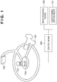
- Fig. 1 is a view showing the arrangement of a visual inspection apparatus according to the embodiment.
- the visual inspection apparatus is an inspection apparatus which senses an object to be inspected that is irradiated with illumination light, and inspects it from the sensed image.
- the visual inspection apparatus generally includes an image sensing means.
- a search range acquisition means 101 includes an input device such as a keyboard or mouse, and a display device such as a monitor.
- the search range acquisition means 101 acquires data within the search range of an object to be inspected.
- the user observes the object displayed on the display device, and inputs a search range with the input device.
- the search range is a region to be inspected when performing a visual inspection.
- An illumination means 102 includes a luminaire using a fluorescent light, halogen lamp, slit-shaped light, area light, LED, prism, or the like.
- the illumination means 102 emits illumination light to enhance the contrast of an object to be inspected.
- An image sensing means 103 senses an object to be inspected that is irradiated with illumination light emitted by the illumination means 102, acquiring the image of the object.
- the image sensing means 103 includes an optical means such as a video camera or infrared sensor.
- a driving means 104 includes a motor and driving gear.
- the motor operates to transfer the driving force to the illumination means 102 and image sensing means 103 via the driving gear, changing the positions of the illumination means 102 and image sensing means 103.
- a control means 105 includes a CPU and RAM.
- the RAM stores a control program for controlling the visual inspection apparatus.
- the CPU reads the control program from the RAM and executes processing based on the control program to control each building component of the visual inspection apparatus.
- the control program includes a driving program for driving the driving means 104, illumination means 102, and image sensing means 103, and an information processing program for processing data in the search range that is transmitted from the search range acquisition means 101.
- An image recoding means 106 includes a recording means such as a hard disk, and records an image acquired by the image sensing means 103.
- the image acquired by the image sensing means 103 is transmitted to the image recoding means 106 via the control means 105.
- An image sensing target 107 undergoes a visual inspection, and includes some assemblies or the like.
- the image sensing target 107 in the embodiment has a defective portion region.
- the defective portion is a scratch, dirt, or the like on the image sensing target 107 and is to be detected in visual inspection.
- the image sensing target 107 is irradiated with illumination light emitted by the illumination means 102 and sensed by the image sensing means 103.
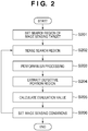
- Fig. 2 shows the sequence of visual inspection processing in the embodiment using the visual inspection apparatus in Fig. 1 .
- processing to detect a defective portion of the image sensing target 107 is performed as an example of visual inspection.
- an image sensing means 201 senses the image sensing target 107 to set the search region of the image sensing target.
- the search region is a region to be inspected when performing a visual inspection.
- the image sensing means 103 senses the image sensing target 107 from a plurality of image sensing directions, acquiring a plurality of images of the image sensing target 107.
- the display device such as a monitor displays the acquired images, and the search region is set based on a user instruction.
- Fig. 3 is a view showing a UI (User Interface) for setting a search region.
- a target image shown in Fig. 3 is an image sensed by the image sensing means 201.
- a UI 301 is used to set a search region by a user who executes a visual inspection.
- the image sensing target 107 undergoes a visual inspection.
- a pointer 302 is used to set the search region of the image sensing target 107 based on a user instruction.
- a search region 303 is the search region of the image sensing target 107 designated with the pointer 302.
- the user operates the pointer 302 on the UI 301 to designate the search region 303 of the image sensing target 107.
- the search range acquisition means 101 acquires data in the designated search region 303.
- the search region 303 designated by the user may be reconfigured to set a new search region 303.
- the reconfiguration method for example, a change of the luminance value or color information (e.g., R, G, and B values) is used. According to this method, a point which forms the boundary of the designated search region 303 is extracted. A change of the luminance value or color information in a region near the extracted point is calculated.
- the point exhibiting the larger change amount is set as a point which forms the boundary of the search region 303. This processing is executed for each point which forms the boundary of the search region 303, thereby reconfiguring the boundary of the search region 303.
- the relative positions of the image sensing means 103 and image sensing target 107 sometimes change.
- the changed relative positions change the search region 303 on the image of the image sensing target 107. Even if the search region 303 changes, an appropriate search region 303 can be set using the method of reconfiguring the search region 303.
- 3D information of the periphery of the image sensing target 107 may be acquired.
- the relative positions of the image sensing target 107 and image sensing means 103 are calculated from the 3D information and used to reconfigure the search region 303.
- the control means 105 functions as an image sensing condition change means. While the control means 105 changes image sensing conditions, the image sensing means 103 senses the search region 303 of the image sensing target 107.
- the image sensing conditions are the positions and orientations of the image sensing means 103 and illumination means 102, the illumination intensity of the illumination means 102, and the like.
- the driving means 104 receives a control instruction from the control means 105 and changes the positions and orientations of the image sensing means 103 and illumination means 102. In accordance with a control instruction from the control means 105, the illumination means 102 changes the illumination intensity.
- the image sensing means 103 senses the image sensing target 107 at every preset timing.
- the number of images to be sensed may be set in advance based on a user instruction.
- the timing at which the set number of images can be sensed is calculated from the driving speeds of the image sensing means 103 and illumination means 102. By this processing, a plurality of images can be acquired under various image sensing conditions.
- the control means 105 functions as an enhancement processing means for enhancing a defective portion region on the sensed image, and executes blur processing for the image acquired in step 202.
- the blur processing is to remove a texture pattern appearing on the surface of an image sensing target and enhance a defective portion region on the sensed image.
- the blur processing means image frequency reduction processing such as averaging processing or filter processing.
- the texture pattern arises from a surface structure such as the material or surface shape of an image sensing target, and appears almost regularly on the surface of the image sensing target. When a defective portion such as a scratch is extracted in visual inspection, the texture pattern is sometimes erroneously detected as a defective portion. To prevent this, the texture pattern is removed from the image of the image sensing target 107 by blur processing to enhance a defective portion region on the sensed image and improve the detection accuracy of the defective portion.
- Fig. 4 is a view exemplifying a texture pattern generated by granular projections appearing on the surface of the image sensing target 107.
- Fig. 4 shows the surface of the image sensing target 107 when the image sensing target 107 is coated with a synthetic resin. As shown in Fig. 4 , small mottles appear. The mottle represents a projection. In Fig. 4 , lines 401 and 402 are set, and luminance values on the respective lines are extracted, obtaining luminance distributions 403 and 404.
- Fig. 5 is a graph showing the enlarged luminance distribution 403 or 404. As is apparent from Fig. 5 , the luminance distribution has a plurality of portions where the luminance change is large. The portions having large luminance changes indicate granular projections.
- the sizes of the projections are almost equal, so luminance widths corresponding to the projections are almost equal.
- the texture pattern is extracted by the following method. First, the luminance widths 501 (distances) on the lines 401 and 402 are collected.
- the average value of all the pixels of an image is calculated, and regions where the luminance value is greatly different from the average value are extracted. Then, the average value of the luminance widths 501 of the extracted regions is calculated. Since the sizes of all projections are almost equal, the average value of the luminance widths 501 becomes almost equal to all the luminance widths corresponding to the texture pattern. Hence, the luminance width 501 almost equal to the average value of the extracted luminance widths 501 can be regarded as the luminance width 501 arising from the texture pattern.
- the extracted region having the luminance width 501 almost equal to the average value is set to the same value as a neighboring luminance value. As a result, the region having the luminance width 501 is deleted, and the image of the surface of the image sensing target 107 from which the texture pattern is deleted can be obtained.
- the image of the surface of the image sensing target 107 can be blurred.
- a variety of blur methods have been proposed.
- the average value of pixels is calculated. According to this method, the average value of pixel values in a region near each pixel of the image of the surface of the image sensing target 107 is calculated first. Then, the target pixel value is replaced with the calculated average value. This processing is executed for all pixels to replace each pixel value with the average value of pixels, obtaining a blurred image.
- a concrete example of blur processing using the average value will be described below.
- Fig. 6 exemplifies another texture pattern appearing on the surface of the image sensing target 107.
- the texture pattern appearing on the surface of the image sensing target 107 shown in Fig. 6 arises from a tile-like rough surface covering the surface of the image sensing target 107.
- a region corresponding to the tile size is set. By calculating the average pixel value of each region, proper blur processing can be done.
- the region corresponding to the tile size is a region set to extract pixels falling in a region near the target pixel.
- a rectangular region 601 larger than the tile is set. Then, averaging processing is executed in the rectangular region 601 by using, as a center, each of all the pixels of the sensed image. By performing averaging processing using the rectangular region 601 larger than the tile, a sensed image free from the seams between tiles can be attained.
- Fig. 7 is a view showing an image obtained by performing blur processing for the image of Fig. 6.
- Fig. 7 reveals that an image in which a defective portion is enhanced can be obtained by performing blur processing.
- Fig. 8 exemplifies still another texture pattern appearing on the surface of the image sensing target 107.
- Fig. 8 shows a state in which a granular pattern is generated on the image sensing target 107.
- Blur processing can be executed by setting a rectangular region 602 double or more the grain in length and breadth and performing averaging processing, similar to the processing in Fig. 6 .
- Fig. 9 is a view showing an image obtained by performing blur processing for the image of Fig. 8 .
- a defective portion can be extracted at higher accuracy by executing blur processing corresponding to the surface structure or material of the image sensing target 107, like the above-described processing.
- rectangular regions corresponding to predetermined texture patterns may be stored in a storage device in advance. In this case, the user selects a texture pattern, and the control means 105 selects an appropriate rectangular region.
- Step 204 the control means 105 functions as a region extraction function and extracts a defective portion region from the image of the surface of the image sensing target 107.
- the image of the image sensing target 107 is blurred.
- a boundary is extracted at which the luminance value changes by a preset or more value. Accordingly, the boundary of the defective portion can be extracted without erroneously detecting the texture pattern as a defective portion.
- the defective portion may be extracted without performing the processing of step 203. For example, all the boundaries of regions where the luminance value changes by a preset value or more are extracted from the image sensing target 107. Then, the coincidence between the known size or shape of the defective portion region and each extracted region is calculated. The coincidence is the quantified value of the similarity between the shapes of two regions that is calculated based on the area difference or the like. Various methods have been proposed as the method of calculating the coincidence between region shapes, and a detailed description thereof will be omitted. By the above processing, the coincidence is calculated, and a region having the highest coincidence is set as a defective portion region.
- Step 205 the control means 105 calculates the evaluation value of each image acquired in step 202.
- the evaluation value is a quantified value representing whether image sensing conditions are suitable for detecting a defective portion.
- the evaluation value is based on the contrast between a defective portion region and the remaining region.
- A1 be the area of the defective portion extracted in step 204 and Q1 be the contrast value in the defective portion region.
- A2 be the area of a region other than the defective portion extracted in step 204 and Q2 be the contrast value of the region other than the defective portion region extracted in step 204.
- the contrast in the defective portion region becomes high and the evaluation value L becomes large.
- a defective portion does not or hardly appears. In this case, the area of the defective portion region is small and the evaluation value becomes low.
- the equation to calculate the evaluation value L is not limited to the above-described one and is arbitrary as long as the evaluation value L reflects the contrast between the defective portion region and the remaining region.
- the sum of the absolute values of luminance values in the defective portion region extracted in step 204 may be used more simply as the evaluation value.
- Step 206 the control means 105 obtains image sensing conditions suited to visual inspection based on the evaluation value calculated in step 205.
- Fig. 10 is a graph showing the correspondence between the intensity of illumination light serving as one image sensing condition and the evaluation value.
- the illuminance intensity is too high, like L7, the shade is hardly generated in the image. Further, the illuminance intensity exceeds a luminance range sensible by the image sensing means, decreasing the contrast between the defective portion and the remaining region. An excessively high illumination intensity results in a small evaluation value, too.
- the evaluation value tends to rise up to the intensity L5 of illumination light and drop from the illumination condition L6.
- An illumination condition under which the evaluation value maximizes should reside between the illumination conditions L5 and L6.
- the control means 105 presents, on the display device such as a monitor, the fact that a better visual inspection can be achieved by setting an illumination condition between the illumination conditions L5 and L6. By checking the display, the user who performs a visual inspection can confirm an image sensing condition suited to the visual inspection. In this processing, the control means 105 functions as the first control means for obtaining an image sensing condition at a predetermined time interval. When the user designates to obtain a more accurate image sensing condition, the process returns to step 202 to execute the foregoing processing.
- the control means 105 functions as the second control means for obtaining a more accurate image sensing condition and limits, to the range between the illumination conditions L5 and L6, the range where the image sensing condition is changed, thereby narrowing the image sensing time interval in step 202.
- the intensity of illumination light having a large evaluation value can be detected at higher accuracy. For example, by calculating evaluation values at L51, L52, and L53 in Fig. 10 , the intensity of illumination light at L52 having a larger evaluation value can be detected. In this fashion, the evaluation value is calculated at the first large time interval. After that, the evaluation value is calculated at the second small time interval within the range where the evaluation value changes from the upward trend to the downward trend. The intensity of illumination light having a large evaluation value can be detected quickly.
- the control means 105 functions as an image sensing condition setting means and sets the image sensing condition obtained by the processing of Fig. 2 as an image sensing condition used when performing a visual inspection.
- An inspection can be achieved at higher detection accuracy by the image sensing apparatus in Fig. 1 functioning as a visual inspection apparatus using image sensing conditions set by the processing of Fig. 2 .
- the intensity of illumination light is mainly used as an image sensing condition.
- the same processing can also be applied to, for example, the relative positions of the image sensing means 103, image sensing target 107, and illumination means 102.
- step 206 the image sensing time interval is narrowed based on a user instruction, and then the processes in step 202 and subsequent steps are executed again. Instead, for example, the process may return to step 206 only by a preset count. When the process returns to step 206 only by a preset count, an appropriate image sensing condition can be easily detected without putting a heavy burden on the user.
- the 2D search region 303 is set based on a user instruction using the UI 301 in Fig. 3 .
- a 3D search region 303 is set in step 201 of Fig. 2 . Processing other than step 201 of Fig. 2 is the same as that in the first embodiment, and a description thereof will not be repeated.
- Fig. 11 is a view showing a UI (User Interface) for setting a search region in the second embodiment.
- the search region 303 is set for an image sensing target 107, similar to the first embodiment. Then, another search region 303 is set for the image sensing target 107 when observed from a direction different from that in Fig. 11 .
- Figs. 12 and 13 are views showing the image sensing target 107 observed from directions different from that in Fig. 11 .
- Fig. 12 is a view showing the image sensing target 107 observed from the side.
- the search region 303 is set to cross the image sensing target 107.
- Fig. 13 is a view showing the image sensing target 107 observed from the back.
- the search region 303 is set to cover the entire region of the image sensing target 107.
- a 3D search region can be set. More specifically, a plurality of 2D search regions are set at 3D coordinates. A space in which no 2D search region is set is complemented by the set 2D search regions, thereby setting a search region.
- the search region 303 is reconfigured to sense an image in various directions.
- the second embodiment can omit reconfiguration processing by setting the 3D search region 303.
- an exceptional region 1102 in Fig. 11 may be set, which has a design, logotype, or the like, is apparently not a defective portion region but may be erroneously detected as a defective portion region.
- the exceptional region 1102 is not referred to in the processing sequence of Fig. 2 .
- the processing speed can be increased.
Landscapes
- Engineering & Computer Science (AREA)
- Physics & Mathematics (AREA)
- General Physics & Mathematics (AREA)
- Signal Processing (AREA)
- Computer Vision & Pattern Recognition (AREA)
- Theoretical Computer Science (AREA)
- Multimedia (AREA)
- Chemical & Material Sciences (AREA)
- Immunology (AREA)
- Life Sciences & Earth Sciences (AREA)
- Quality & Reliability (AREA)
- Analytical Chemistry (AREA)
- Biochemistry (AREA)
- General Health & Medical Sciences (AREA)
- Health & Medical Sciences (AREA)
- Pathology (AREA)
- Human Computer Interaction (AREA)
- Studio Devices (AREA)
- Investigating Materials By The Use Of Optical Means Adapted For Particular Applications (AREA)
- Image Processing (AREA)
- Image Analysis (AREA)
Claims (13)
- Bilderfassungsvorrichtung, mit:einer Bilderfassungseinrichtung (103) zum Erfassen eines Bilderfassungsziels, um eine Vielzahl von erfassten Bildern zu beschaffen, wobei das Bilderfassungsziel eine defekte Abschnittsregion aufweist;einer Beleuchtungseinrichtung (102) zum Beleuchten des Bilderfassungsziels in der Bilderfassung durch die Bilderfassungseinrichtung;einer Bilderfassungsbedingungsänderungseinrichtung (105) zum Ändern einer Bilderfassungsbedingung während des Erfassens des Bilderfassungsziels;gekennzeichnet durcheine Berechnungseinrichtung (105) zum Berechnen, als einen Evaluierungswert, von Informationen bezüglich eines Kontrasts von jedem der erfassten Bilder, die durch die Bilderfassungseinrichtung beschafft werden, wobei der Evaluierungswert basierend auf einem Verhältnis von i) einem Produkt eines Kontrastwerts und eines Bereichs der defekten Abschnittsregion und ii) einem Produkt eines Kontrastwerts und eines Bereichs einer anderen Region als der defekten Abschnittsregion berechnet wird;eine erste Steuerungseinrichtung (105) zum Steuern der Bilderfassungsbedingungsänderungseinrichtung, um die Bilderfassungsbedingung zu ändern, der Bilderfassungseinrichtung, um die Bilderfassungsziels parallel mit der Änderung der Bilderfassungsbedingung zu jedem vorbestimmten ersten Schritt des Änderns der Bilderfassungsbedingung zu erfassen, und der Berechnungseinrichtung, um einen Evaluierungswert von jedem der erfassten Bilder zu berechnen;eine zweite Steuerungseinrichtung (105) zum Steuern, nach der Steuerung durch die erste Steuerungseinrichtung, der Bilderfassungsbedingungsänderungseinrichtung, um die Bilderfassungsbedingung innerhalb eines Bereichs, in dem sich der Evaluierungswert, der durch die erste Steuerungseinrichtung erfasst wird, von einer Erhöhung zu einer Verringerung ändert, zu ändern, der Bilderfassungseinrichtung, um das Bilderfassungsziel parallel mit der Änderung der Bilderfassungsbedingung zu jedem vorbestimmten zweiten Schritt des Änderns der Bilderfassungsbedingung zu erfassen, wobei der vorbestimmte zweite Schritt enger als der vorbestimmte erste Schritt ist, und der Berechnungseinrichtung, um einen Evaluierungswert von jedem der erfassten Bilder zu berechnen; undeine Bilderfassungsbedingungseinstelleinrichtung (105) zum Einstellen der Bilderfassungsbedingung basierend auf dem Evaluierungswert, der durch die zweite Steuerungseinrichtung erhalten wird.
- Bilderfassungsvorrichtung gemäß Anspruch 1, wobei die Bilderfassungsbedingung entweder eine Intensität des Beleuchtungslichts durch die Beleuchtungseinrichtung oder relative Positionen der Bilderfassungseinrichtung, des Bilderfassungsziels und der Beleuchtungseinrichtung aufweist.
- Bilderfassungsvorrichtung gemäß Anspruch 1, weiterhin mit einer Bereichsextrahierungseinrichtung (105) zum Extrahieren eines Suchbereichs, der bezüglich der defekten Abschnittsregion des Bilderfassungsziels zu inspizieren ist, basierend auf einer Benutzeranweisung.
- Bilderfassungsvorrichtung, mit:einer Bilderfassungseinrichtung (103) zum Erfassen eines Bilderfassungsziels, um ein erfasstes Bild zu beschaffen; undeiner Verbesserungsverarbeitungseinrichtung (105) zum Verbessern einer defekten Abschnittsregion auf dem erfassten Bild, das durch die Bilderfassungseinrichtung beschafft wird, durch Entfernen eines Texturmusters, das auf einer Oberfläche des Bilderfassungsziels erscheint, durch eine Unschärfeverarbeitung ;gekennzeichnet durcheine Bilderfassungsbedingungseinstelleinrichtung (105) zum Einstellen einer Bilderfassungsbedingung der Bilderfassungseinrichtung basierend auf einem Evaluierungswert des erfassten Bildes, in dem die defekte Abschnittsregion verbessert ist, wobei der Evaluierungswert basierend auf einem Verhältnis von i) einem Produkt eines Kontrastwerts und eines Bereichs der defekten Abschnittsregion und ii) einem Produkt eines Kontrastwerts und eines Bereichs einer anderen Region als der defekten Abschnittsregion berechnet wird.
- Bilderfassungsvorrichtung gemäß Anspruch 4, wobei die Verbesserungsverarbeitungseinrichtung (105) einen Nachbarbereich eines Pixels, der das erfasste Bild formt, einstellt, und einen Pixelwert des Pixels auf einen Durchschnittspixelwert in dem Nachbarbereich einstellt, oderweiterhin mit einer Einrichtung zum Berechnen (105), als einen Evaluierungswert, von Informationen bezüglich eines Kontrasts des erfassten Bildes, in dem die defekte Abschnittsregion verbessert ist, und Einstellen einer Bilderfassungsbedingung basierend auf einem Bereich, in dem sich der berechnete Evaluierungswert von einer Erhöhung zu einer Verringerung ändert, oderwobei die Bilderfassungsbedingung entweder eine Intensität eines Beleuchtungslichts durch eine Beleuchtungseinrichtung oder relative Positionen der Bilderfassungseinrichtung, des Bilderfassungsziels und der Beleuchtungseinrichtung umfasst, oderwobei das Texturmuster, das auf der Oberfläche des Bilderfassungsziels erscheint, durch das Material einer Oberfläche des Bilderfassungsziels entsteht.
- Bilderfassungsvorrichtung gemäß Anspruch 1, weiterhin mit:einer Verbesserungsverarbeitungseinrichtung (105) zum Verbessern einer defekten Abschnittsregion auf dem erfassten Bild durch Entfernen eines Texturmusters, das auf der Oberfläche des Bilderfassungsziels erscheint, durch eine Unschärfeverarbeitung;wobei die Berechnungseinrichtung weiterhin zum Berechnen eines Evaluierungswerts als Informationen bezüglich eines Kontrasts des erfassten Bildes, in dem die defekte Abschnittsregion verbessert wird, dient.
- Bilderfassungsvorrichtung gemäß einem der Ansprüche 1 bis 5, weiterhin mit einer visuellen Inspektionseinrichtung zum Durchführen einer visuellen Inspektion des Bilderfassungsziels unter Verwendung der Bilderfassungsbedingung, die durch die Bilderfassungsbedingungseinstelleinrichtung eingestellt ist.
- Bilderfassungsverfahren, mit:einem Bilderfassungsschritt des Veranlassens einer Bilderfassungseinrichtung, ein Bilderfassungsziel zu erfassen und eine Vielzahl von erfassten Bildern aufzunehmen, wobei das Bilderfassungsziel eine defekte Abschnittsregion aufweist;einem Beleuchtungsschritt des Veranlassens einer Beleuchtungseinrichtung, das Bilderfassungsziel in der Bilderfassung durch die Bilderfassungseinrichtung zu beleuchten;einem Bilderfassungsbedingungsänderungsschritt des Veranlassens der Bilderfassungsbedingungsänderungseinrichtung, eine Bilderfassungsbedingung während des Erfassens des Bilderfassungsziels zu ändern;gekennzeichnet durcheinen Berechnungsschritt des Veranlassens der Berechnungseinrichtung, einen Evaluierungswert zu berechnen, als Informationen bezüglich eines Kontrasts von jedem der erfassten Bilder, die durch die Bilderfassungseinrichtung beschafft werden, wobei der Evaluierungswert basierend auf einem Verhältnis von i) einem Produkt eines Kontrastwerts und eines Bereichs der defekten Abschnittsregion und ii) einem Produkt eines Kontrastwerts und eines Bereichs einer anderen Region als der defekten Abschnittsregion berechnet wird;einen ersten Steuerungsschritt des Veranlassens einer ersten Steuerungseinrichtung, die Bilderfassungsbedingungsänderungseinrichtung zu steuern, um die Bilderfassungsbedingung zu ändern, die Bilderfassungseinrichtung zu steuern, um das Bilderfassungsziel parallel mit der Änderung der Bilderfassungsbedingung zu jedem vorbestimmten ersten Schritt des Änderns der Bilderfassungsbedingung zu erfassen, und die Berechnungseinrichtung zu steuern, einen Evaluierungswert von jedem der erfassten Bilder zu berechnen;einen zweiten Steuerungsschritt, nach dem ersten Steuerungsschritt, des Veranlassens der zweiten Steuerungseinrichtung, die Bilderfassungsbedingungsänderungseinrichtung zu steuern, die Bilderfassungsbedingung innerhalb eines Bereichs, in dem sich der Evaluierungswert, der in dem ersten Steuerungsschritt erhalten wird, von einer Erhöhung zu einer Verringerung ändert, zu ändern, die Bilderfassungseinrichtung zu steuern, um das Bilderfassungsziel parallel mit der Änderung der Bilderfassungsbedingung zu jedem vorbestimmten zweiten Schritt des Änderns der Bilderfassungsbedingung zu erfassen, wobei der vorbestimmte zweite Schritt enger als der vorbestimmte erste Schritt ist, und die Berechnungseinrichtung zu steuern, einen Evaluierungswert von jedem der erfassten Bilder zu berechnen; undeinen Bilderfassungsbedingungseinstellungsschritt des Änderns der Bilderfassungsbedingung basierend auf dem Evaluierungswert, der in dem zweiten Steuerungsschritt erhalten wird.
- Bilderfassungsverfahren, mit:einem Bilderfassungsschritt des Veranlassens einer Bilderfassungseinrichtung, ein Bilderfassungsziel aufzunehmen und ein erfasstes Bild zu beschaffen; undeinem Verbesserungsverarbeitungsschritt des Veranlassens einer Verbesserungsverarbeitungseinrichtung, eine defekte Abschnittsregion auf dem erfassten Bild, das durch die Bilderfassungseinrichtung beschafft wird, zu verbessern, durch Entfernen eines Texturmusters, das auf einer Oberfläche des Bilderfassungsziels erscheint, durch eine Unschärfeverarbeitung;gekennzeichnet durcheinen Bilderfassungsbedingungseinstellungsschritt des Veranlassens einer Bilderfassungsbedingungseinstelleinrichtung, eine Bilderfassungsbedingung der Bilderfassungseinrichtung einzustellen, basierend auf einem Evaluierungswert des erfassten Bildes, in dem die defekte Abschnittsregion verbessert wird, wobei der Evaluierungswert basierend auf einem Verhältnis von i) einem Produkt eines Kontrastwerts und eines Bereichs der defekten Abschnittsregion und ii) einem Produkt eines Kontrastwerts und eines Bereichs einer anderen Region als der defekten Abschnittsregion berechnet wird.
- Bilderfassungsverfahren gemäß Anspruch 8, weiterhin mit:einem Verbesserungsverarbeitungsschritt des Veranlassens einer Verbesserungsverarbeitungseinrichtung, eine defekte Abschnittsregion auf dem erfassten Bild zu verbessern, durch Entfernen eines Texturmusters, das auf der Oberfläche des Bilderfassungsziels erscheint, durch eine Unschärfeverarbeitung ;einem Berechnungsschritt des Veranlassens der Berechnungseinrichtung, einen Evaluierungswert als Informationen bezüglich eines Kontrasts des erfassten Bildes, in dem die defekte Abschnittsregion verbessert wird, zu berechnen.
- Programm zum Veranlassen eines Computers, um zu arbeiten alseine Bilderfassungseinrichtung (103) zum Erfassen eines Bilderfassungsziels, um eine Vielzahl von erfassten Bildern zu beschaffen, wobei das Bilderfassungsziel eine defekte Abschnittsregion aufweist;eine Beleuchtungseinrichtung (102) zum Beleuchten des Bilderfassungsziels in der Bilderfassung durch die Bilderfassungseinrichtung;eine Bilderfassungsbedingungsänderungseinrichtung (105) zum Ändern einer Bilderfassungsbedingung während des Erfassens des Bilderfassungsziels;gekennzeichnet durcheine Berechnungseinrichtung (105) zum Berechnen, als einen Evaluierungswert, von Informationen bezüglich eines Kontrasts von jedem der erfassten Bilder, die durch die Bilderfassungseinrichtung beschafft werden, wobei der Evaluierungswert basierend auf einem Verhältnis von i) einem Produkt eines Kontrastwerts und eines Bereichs der defekten Abschnittsregion und ii) einem Produkt eines Kontrastwerts und eines Bereichs einer anderen Region als der defekten Abschnittsregion berechnet wird;eine erste Steuerungseinrichtung (105) zum Steuern der Bilderfassungsbedingungsänderungseinrichtung, um die Bilderfassungsbedingung zu ändern, der Bilderfassungseinrichtung, um die Bilderfassungsziels parallel mit der Änderung der Bilderfassungsbedingung zu jedem vorbestimmten ersten Schritt des Änderns der Bilderfassungsbedingung zu erfassen, und der Berechnungseinrichtung, um einen Evaluierungswert von jedem der erfassten Bilder zu berechnen;eine zweite Steuerungseinrichtung (105) zum Steuern, nach der Steuerung durch die erste Steuerungseinrichtung, der Bilderfassungsbedingungsänderungseinrichtung, um die Bilderfassungsbedingung innerhalb eines Bereichs, in dem sich der Evaluierungswert, der durch die erste Steuerungseinrichtung erfasst wird, von einer Erhöhung zu einer Verringerung ändert, zu ändern, der Bilderfassungseinrichtung, um das Bilderfassungsziel parallel mit der Änderung der Bilderfassungsbedingung zu jedem vorbestimmten zweiten Schritt des Änderns der Bilderfassungsbedingung zu erfassen, wobei der vorbestimmte zweite Schritt enger als der vorbestimmte erste Schritt ist, und der Berechnungseinrichtung, um einen Evaluierungswert von jedem der erfassten Bilder zu berechnen; undeine Bilderfassungsbedingungseinstelleinrichtung (105) zum Einstellen der Bilderfassungsbedingung basierend auf dem Evaluierungswert, der durch die zweite Steuerungseinrichtung erhalten wird.
- Programm zum Veranlassen eines Computers, um als eine Bilderfassungsvorrichtung zu arbeiten, mit:einer Bilderfassungseinrichtung (103) zum Erfassen eines Bilderfassungsziels, um ein erfasstes Bild zu beschaffen; undeiner Verbesserungsverarbeitungseinrichtung (105) zum Verbessern einer defekten Abschnittsregion auf dem erfassten Bild, das durch die Bilderfassungseinrichtung beschafft wird, durch Entfernen eines Texturmusters, das auf einer Oberfläche des Bilderfassungsziels erscheint, durch eine Unschärfeverarbeitung ;gekennzeichnet durcheine Bilderfassungsbedingungseinstelleinrichtung (105) zum Einstellen einer Bilderfassungsbedingung der Bilderfassungseinrichtung basierend auf einem Evaluierungswert des erfassten Bildes, in dem die defekte Abschnittsregion verbessert ist, wobei der Evaluierungswert basierend auf einem Verhältnis von i) einem Produkt eines Kontrastwerts und eines Bereichs der defekten Abschnittsregion und ii) einem Produkt eines Kontrastwerts und eines Bereichs einer anderen Region als der defekten Abschnittsregion berechnet wird.
- Programm gemäß Anspruch 11, um weiterhin einen Computer zu veranlassen, um zu arbeiten alseine Verbesserungsverarbeitungseinrichtung zum Verbessern einer defekten Abschnittsregion auf dem erfassten Bild durch Entfernen eines Texturmusters, das auf der Oberfläche des Bilderfassungsziels erscheint, durch eine Unschärfeverarbeitung, undeine Berechnungseinrichtung zum Berechnen eines Evaluierungswerts als Informationen bezüglich eines Kontrasts des erfassten Bildes, in dem die defekte Abschnittsregion verbessert wird.
Applications Claiming Priority (2)
| Application Number | Priority Date | Filing Date | Title |
|---|---|---|---|
| JP2007172749A JP4906609B2 (ja) | 2007-06-29 | 2007-06-29 | 撮像装置および方法 |
| PCT/JP2008/059888 WO2009004874A1 (ja) | 2007-06-29 | 2008-05-29 | 撮像装置および方法 |
Publications (3)
| Publication Number | Publication Date |
|---|---|
| EP2173087A1 EP2173087A1 (de) | 2010-04-07 |
| EP2173087A4 EP2173087A4 (de) | 2017-10-11 |
| EP2173087B1 true EP2173087B1 (de) | 2019-07-31 |
Family
ID=40225930
Family Applications (1)
| Application Number | Title | Priority Date | Filing Date |
|---|---|---|---|
| EP08764857.2A Active EP2173087B1 (de) | 2007-06-29 | 2008-05-29 | Verbessertes einstellen von bilderfassungsbedingungen für die detektion von defekten |
Country Status (6)
| Country | Link |
|---|---|
| US (2) | US8237848B2 (de) |
| EP (1) | EP2173087B1 (de) |
| JP (1) | JP4906609B2 (de) |
| KR (1) | KR101141811B1 (de) |
| CN (1) | CN101803364B (de) |
| WO (1) | WO2009004874A1 (de) |
Families Citing this family (9)
| Publication number | Priority date | Publication date | Assignee | Title |
|---|---|---|---|---|
| JP5875186B2 (ja) * | 2012-04-27 | 2016-03-02 | シブヤ精機株式会社 | 農産物検査装置及び農産物検査方法 |
| JP6261443B2 (ja) * | 2013-06-26 | 2018-01-17 | キヤノン株式会社 | 分光情報を処理する情報処理装置及び情報処理方法 |
| JP6736270B2 (ja) | 2015-07-13 | 2020-08-05 | キヤノン株式会社 | 画像処理装置及び画像処理装置の作動方法 |
| CN106487915B (zh) * | 2016-10-31 | 2019-08-20 | 维沃移动通信有限公司 | 一种图片处理方法及服务器 |
| JP6917761B2 (ja) * | 2017-05-09 | 2021-08-11 | 株式会社キーエンス | 画像検査装置 |
| JP7077807B2 (ja) * | 2018-06-12 | 2022-05-31 | オムロン株式会社 | 画像検査システム及びその制御方法 |
| JP2022526473A (ja) * | 2020-03-11 | 2022-05-25 | ベイジン バイドゥ ネットコム サイエンス テクノロジー カンパニー リミテッド | 情報を取得するための方法および装置、電子機器、記憶媒体並びにコンピュータプログラム |
| JP2022160288A (ja) * | 2021-04-06 | 2022-10-19 | パナソニックIpマネジメント株式会社 | 検査システムおよび画像処理装置 |
| JP7573505B2 (ja) * | 2021-10-08 | 2024-10-25 | 三菱電機株式会社 | 遠隔検査装置及び遠隔検査方法 |
Citations (2)
| Publication number | Priority date | Publication date | Assignee | Title |
|---|---|---|---|---|
| US20030016214A1 (en) * | 2001-07-19 | 2003-01-23 | Junji Sukeno | Imaging device |
| US20070121106A1 (en) * | 2005-11-29 | 2007-05-31 | Yukihiro Shibata | Apparatus and method for optical inspection |
Family Cites Families (27)
| Publication number | Priority date | Publication date | Assignee | Title |
|---|---|---|---|---|
| US4975972A (en) * | 1988-10-18 | 1990-12-04 | At&T Bell Laboratories | Method and apparatus for surface inspection |
| EP0475454A3 (en) * | 1990-09-14 | 1992-10-14 | Fuji Photo Film Co., Ltd. | Defect inspection system |
| US5353357A (en) * | 1992-12-04 | 1994-10-04 | Philip Morris Incorporated | Methods and apparatus for inspecting the appearance of substantially circular objects |
| US5845002A (en) * | 1994-11-03 | 1998-12-01 | Sunkist Growers, Inc. | Method and apparatus for detecting surface features of translucent objects |
| JP3201217B2 (ja) * | 1995-04-17 | 2001-08-20 | 日産自動車株式会社 | 表面欠陥検査装置 |
| US6259827B1 (en) * | 1996-03-21 | 2001-07-10 | Cognex Corporation | Machine vision methods for enhancing the contrast between an object and its background using multiple on-axis images |
| JPH11281585A (ja) * | 1998-03-26 | 1999-10-15 | Nikon Corp | 検査方法及び装置 |
| US6788411B1 (en) * | 1999-07-08 | 2004-09-07 | Ppt Vision, Inc. | Method and apparatus for adjusting illumination angle |
| JP2001185591A (ja) * | 1999-12-27 | 2001-07-06 | Hitachi Ltd | 欠陥の詳細検査方法および装置 |
| JP2001202496A (ja) * | 2000-01-18 | 2001-07-27 | Dainippon Printing Co Ltd | 画像入力装置 |
| KR100795286B1 (ko) * | 2000-03-24 | 2008-01-15 | 올림푸스 가부시키가이샤 | 결함검출장치 |
| EP1255224A1 (de) * | 2001-05-02 | 2002-11-06 | STMicroelectronics S.r.l. | System und Verfahren zur Analyse von Oberflächenfehlern |
| US6944331B2 (en) * | 2001-10-26 | 2005-09-13 | National Instruments Corporation | Locating regions in a target image using color matching, luminance pattern matching and hue plane pattern matching |
| JP3601031B2 (ja) | 2002-03-06 | 2004-12-15 | 有限会社テクノドリーム二十一 | 画像データ計測装置及び画像データを用いた対象物体の自由変形を含む任意視点画像作成方法 |
| JP4251312B2 (ja) * | 2002-03-08 | 2009-04-08 | 日本電気株式会社 | 画像入力装置 |
| JP2003270163A (ja) * | 2002-03-15 | 2003-09-25 | Dainippon Printing Co Ltd | 検査方法および装置 |
| US6950546B2 (en) * | 2002-12-03 | 2005-09-27 | Og Technologies, Inc. | Apparatus and method for detecting surface defects on a workpiece such as a rolled/drawn metal bar |
| JP2005003476A (ja) * | 2003-06-11 | 2005-01-06 | Nikon Corp | 表面検査装置 |
| JP2005157268A (ja) * | 2003-11-06 | 2005-06-16 | Canon Inc | 撮像装置及びその制御方法及びプログラム及び記憶媒体 |
| JP4539964B2 (ja) * | 2004-07-21 | 2010-09-08 | 大日本スクリーン製造株式会社 | 画像の領域分割 |
| JP4562126B2 (ja) * | 2004-09-29 | 2010-10-13 | 大日本スクリーン製造株式会社 | 欠陥検出装置および欠陥検出方法 |
| JP4591325B2 (ja) * | 2005-01-28 | 2010-12-01 | カシオ計算機株式会社 | 撮像装置及びプログラム |
| US7679758B2 (en) * | 2005-04-29 | 2010-03-16 | Microview Technologies Pte Ltd. | Fastener inspection system and method |
| JP4625716B2 (ja) * | 2005-05-23 | 2011-02-02 | 株式会社日立ハイテクノロジーズ | 欠陥検査装置及び欠陥検査方法 |
| TW200742923A (en) * | 2006-05-11 | 2007-11-16 | Asia Optical Co Inc | Method of auto focus |
| US8008641B2 (en) * | 2007-08-27 | 2011-08-30 | Acushnet Company | Method and apparatus for inspecting objects using multiple images having varying optical properties |
| JP2010271600A (ja) * | 2009-05-22 | 2010-12-02 | Sanyo Electric Co Ltd | 電子カメラ |
-
2007
- 2007-06-29 JP JP2007172749A patent/JP4906609B2/ja not_active Expired - Fee Related
-
2008
- 2008-05-29 CN CN200880022754XA patent/CN101803364B/zh not_active Expired - Fee Related
- 2008-05-29 KR KR1020107001413A patent/KR101141811B1/ko not_active Expired - Fee Related
- 2008-05-29 EP EP08764857.2A patent/EP2173087B1/de active Active
- 2008-05-29 WO PCT/JP2008/059888 patent/WO2009004874A1/ja not_active Ceased
-
2009
- 2009-12-29 US US12/649,079 patent/US8237848B2/en not_active Expired - Fee Related
-
2012
- 2012-07-10 US US13/545,689 patent/US8610770B2/en not_active Expired - Fee Related
Patent Citations (2)
| Publication number | Priority date | Publication date | Assignee | Title |
|---|---|---|---|---|
| US20030016214A1 (en) * | 2001-07-19 | 2003-01-23 | Junji Sukeno | Imaging device |
| US20070121106A1 (en) * | 2005-11-29 | 2007-05-31 | Yukihiro Shibata | Apparatus and method for optical inspection |
Also Published As
| Publication number | Publication date |
|---|---|
| CN101803364B (zh) | 2013-05-01 |
| EP2173087A4 (de) | 2017-10-11 |
| EP2173087A1 (de) | 2010-04-07 |
| US8610770B2 (en) | 2013-12-17 |
| CN101803364A (zh) | 2010-08-11 |
| KR20100025001A (ko) | 2010-03-08 |
| JP4906609B2 (ja) | 2012-03-28 |
| US20120274794A1 (en) | 2012-11-01 |
| US20100171852A1 (en) | 2010-07-08 |
| KR101141811B1 (ko) | 2012-05-14 |
| US8237848B2 (en) | 2012-08-07 |
| WO2009004874A1 (ja) | 2009-01-08 |
| JP2009010890A (ja) | 2009-01-15 |
Similar Documents
| Publication | Publication Date | Title |
|---|---|---|
| US8610770B2 (en) | Image sensing apparatus and method for sensing target that has defective portion region | |
| CN102084213B (zh) | 轮胎形状检查方法、轮胎形状检查装置 | |
| JP6620477B2 (ja) | コンクリートのひび割れ検出方法及び検出プログラム | |
| KR20130142118A (ko) | 타이어의 트레드 디자인을 형성하는 기본 패턴을 식별하여 규정하기 위한 방법 | |
| JP7230507B2 (ja) | 付着物検出装置 | |
| JP4139291B2 (ja) | 欠陥検査方法及び装置 | |
| JP4150390B2 (ja) | 外観検査方法及び外観検査装置 | |
| KR101977647B1 (ko) | 표시장치의 얼룩 검출 장치 및 방법 | |
| US9628659B2 (en) | Method and apparatus for inspecting an object employing machine vision | |
| JP5932413B2 (ja) | ワークの位置ずれ検出装置、ワークの位置ずれ検出方法、及びコンピュータプログラム | |
| US10788430B2 (en) | Surface inspection apparatus and surface inspection method | |
| JP6114559B2 (ja) | フラットパネルディスプレイの自動ムラ検出装置 | |
| EP4010873B1 (de) | Verwendung eines hdr-bildes in einem visuellen prüfungsverfahren | |
| JP4279833B2 (ja) | 外観検査方法及び外観検査装置 | |
| KR101521620B1 (ko) | 다이 영상 분할 방법 | |
| JP2014174003A (ja) | 画像検査方法および画像検査装置 | |
| CN106504251A (zh) | 一种基于图片处理的电子铝箔立方织构含量检测方法 | |
| JP4978215B2 (ja) | 加工面欠陥判定方法 | |
| JP6891429B2 (ja) | 線状縞模様除去方法、タイヤ内面検査方法、及びタイヤ内面検査装置 | |
| JP4135367B2 (ja) | 欠陥部分検出方法 | |
| JP2005265828A (ja) | 疵検出方法及び装置 | |
| JP7712235B2 (ja) | 粒径測定装置、該方法および該プログラム | |
| WO2005043141A1 (en) | An on-line inspection system | |
| JP2002109513A (ja) | 塗装欠陥検出装置およびマスク画像作成方法 | |
| JP2007109121A (ja) | 画像処理装置 |
Legal Events
| Date | Code | Title | Description |
|---|---|---|---|
| PUAI | Public reference made under article 153(3) epc to a published international application that has entered the european phase |
Free format text: ORIGINAL CODE: 0009012 |
|
| 17P | Request for examination filed |
Effective date: 20100129 |
|
| AK | Designated contracting states |
Kind code of ref document: A1 Designated state(s): AT BE BG CH CY CZ DE DK EE ES FI FR GB GR HR HU IE IS IT LI LT LU LV MC MT NL NO PL PT RO SE SI SK TR |
|
| AX | Request for extension of the european patent |
Extension state: AL BA MK RS |
|
| DAX | Request for extension of the european patent (deleted) | ||
| REG | Reference to a national code |
Ref country code: DE Ref legal event code: R079 Ref document number: 602008060782 Country of ref document: DE Free format text: PREVIOUS MAIN CLASS: H04N0005225000 Ipc: G01N0021880000 |
|
| RA4 | Supplementary search report drawn up and despatched (corrected) |
Effective date: 20170913 |
|
| RIC1 | Information provided on ipc code assigned before grant |
Ipc: G06T 7/00 20170101ALI20170907BHEP Ipc: H04N 5/232 20060101ALI20170907BHEP Ipc: H04N 5/225 20060101ALI20170907BHEP Ipc: G01N 21/88 20060101AFI20170907BHEP Ipc: G06T 5/00 20060101ALI20170907BHEP |
|
| STAA | Information on the status of an ep patent application or granted ep patent |
Free format text: STATUS: EXAMINATION IS IN PROGRESS |
|
| 17Q | First examination report despatched |
Effective date: 20180416 |
|
| GRAP | Despatch of communication of intention to grant a patent |
Free format text: ORIGINAL CODE: EPIDOSNIGR1 |
|
| STAA | Information on the status of an ep patent application or granted ep patent |
Free format text: STATUS: GRANT OF PATENT IS INTENDED |
|
| INTG | Intention to grant announced |
Effective date: 20190212 |
|
| GRAS | Grant fee paid |
Free format text: ORIGINAL CODE: EPIDOSNIGR3 |
|
| GRAA | (expected) grant |
Free format text: ORIGINAL CODE: 0009210 |
|
| STAA | Information on the status of an ep patent application or granted ep patent |
Free format text: STATUS: THE PATENT HAS BEEN GRANTED |
|
| AK | Designated contracting states |
Kind code of ref document: B1 Designated state(s): AT BE BG CH CY CZ DE DK EE ES FI FR GB GR HR HU IE IS IT LI LT LU LV MC MT NL NO PL PT RO SE SI SK TR |
|
| REG | Reference to a national code |
Ref country code: CH Ref legal event code: EP Ref country code: GB Ref legal event code: FG4D |
|
| REG | Reference to a national code |
Ref country code: DE Ref legal event code: R096 Ref document number: 602008060782 Country of ref document: DE |
|
| REG | Reference to a national code |
Ref country code: AT Ref legal event code: REF Ref document number: 1161444 Country of ref document: AT Kind code of ref document: T Effective date: 20190815 |
|
| REG | Reference to a national code |
Ref country code: IE Ref legal event code: FG4D |
|
| REG | Reference to a national code |
Ref country code: NL Ref legal event code: MP Effective date: 20190731 |
|
| REG | Reference to a national code |
Ref country code: LT Ref legal event code: MG4D |
|
| REG | Reference to a national code |
Ref country code: AT Ref legal event code: MK05 Ref document number: 1161444 Country of ref document: AT Kind code of ref document: T Effective date: 20190731 |
|
| PG25 | Lapsed in a contracting state [announced via postgrant information from national office to epo] |
Ref country code: BG Free format text: LAPSE BECAUSE OF FAILURE TO SUBMIT A TRANSLATION OF THE DESCRIPTION OR TO PAY THE FEE WITHIN THE PRESCRIBED TIME-LIMIT Effective date: 20191031 Ref country code: SE Free format text: LAPSE BECAUSE OF FAILURE TO SUBMIT A TRANSLATION OF THE DESCRIPTION OR TO PAY THE FEE WITHIN THE PRESCRIBED TIME-LIMIT Effective date: 20190731 Ref country code: NL Free format text: LAPSE BECAUSE OF FAILURE TO SUBMIT A TRANSLATION OF THE DESCRIPTION OR TO PAY THE FEE WITHIN THE PRESCRIBED TIME-LIMIT Effective date: 20190731 Ref country code: AT Free format text: LAPSE BECAUSE OF FAILURE TO SUBMIT A TRANSLATION OF THE DESCRIPTION OR TO PAY THE FEE WITHIN THE PRESCRIBED TIME-LIMIT Effective date: 20190731 Ref country code: NO Free format text: LAPSE BECAUSE OF FAILURE TO SUBMIT A TRANSLATION OF THE DESCRIPTION OR TO PAY THE FEE WITHIN THE PRESCRIBED TIME-LIMIT Effective date: 20191031 Ref country code: HR Free format text: LAPSE BECAUSE OF FAILURE TO SUBMIT A TRANSLATION OF THE DESCRIPTION OR TO PAY THE FEE WITHIN THE PRESCRIBED TIME-LIMIT Effective date: 20190731 Ref country code: FI Free format text: LAPSE BECAUSE OF FAILURE TO SUBMIT A TRANSLATION OF THE DESCRIPTION OR TO PAY THE FEE WITHIN THE PRESCRIBED TIME-LIMIT Effective date: 20190731 Ref country code: PT Free format text: LAPSE BECAUSE OF FAILURE TO SUBMIT A TRANSLATION OF THE DESCRIPTION OR TO PAY THE FEE WITHIN THE PRESCRIBED TIME-LIMIT Effective date: 20191202 Ref country code: LT Free format text: LAPSE BECAUSE OF FAILURE TO SUBMIT A TRANSLATION OF THE DESCRIPTION OR TO PAY THE FEE WITHIN THE PRESCRIBED TIME-LIMIT Effective date: 20190731 |
|
| PG25 | Lapsed in a contracting state [announced via postgrant information from national office to epo] |
Ref country code: ES Free format text: LAPSE BECAUSE OF FAILURE TO SUBMIT A TRANSLATION OF THE DESCRIPTION OR TO PAY THE FEE WITHIN THE PRESCRIBED TIME-LIMIT Effective date: 20190731 Ref country code: GR Free format text: LAPSE BECAUSE OF FAILURE TO SUBMIT A TRANSLATION OF THE DESCRIPTION OR TO PAY THE FEE WITHIN THE PRESCRIBED TIME-LIMIT Effective date: 20191101 Ref country code: LV Free format text: LAPSE BECAUSE OF FAILURE TO SUBMIT A TRANSLATION OF THE DESCRIPTION OR TO PAY THE FEE WITHIN THE PRESCRIBED TIME-LIMIT Effective date: 20190731 Ref country code: IS Free format text: LAPSE BECAUSE OF FAILURE TO SUBMIT A TRANSLATION OF THE DESCRIPTION OR TO PAY THE FEE WITHIN THE PRESCRIBED TIME-LIMIT Effective date: 20191130 |
|
| PG25 | Lapsed in a contracting state [announced via postgrant information from national office to epo] |
Ref country code: TR Free format text: LAPSE BECAUSE OF FAILURE TO SUBMIT A TRANSLATION OF THE DESCRIPTION OR TO PAY THE FEE WITHIN THE PRESCRIBED TIME-LIMIT Effective date: 20190731 |
|
| PG25 | Lapsed in a contracting state [announced via postgrant information from national office to epo] |
Ref country code: PL Free format text: LAPSE BECAUSE OF FAILURE TO SUBMIT A TRANSLATION OF THE DESCRIPTION OR TO PAY THE FEE WITHIN THE PRESCRIBED TIME-LIMIT Effective date: 20190731 Ref country code: RO Free format text: LAPSE BECAUSE OF FAILURE TO SUBMIT A TRANSLATION OF THE DESCRIPTION OR TO PAY THE FEE WITHIN THE PRESCRIBED TIME-LIMIT Effective date: 20190731 Ref country code: DK Free format text: LAPSE BECAUSE OF FAILURE TO SUBMIT A TRANSLATION OF THE DESCRIPTION OR TO PAY THE FEE WITHIN THE PRESCRIBED TIME-LIMIT Effective date: 20190731 Ref country code: EE Free format text: LAPSE BECAUSE OF FAILURE TO SUBMIT A TRANSLATION OF THE DESCRIPTION OR TO PAY THE FEE WITHIN THE PRESCRIBED TIME-LIMIT Effective date: 20190731 Ref country code: IT Free format text: LAPSE BECAUSE OF FAILURE TO SUBMIT A TRANSLATION OF THE DESCRIPTION OR TO PAY THE FEE WITHIN THE PRESCRIBED TIME-LIMIT Effective date: 20190731 |
|
| PG25 | Lapsed in a contracting state [announced via postgrant information from national office to epo] |
Ref country code: IS Free format text: LAPSE BECAUSE OF FAILURE TO SUBMIT A TRANSLATION OF THE DESCRIPTION OR TO PAY THE FEE WITHIN THE PRESCRIBED TIME-LIMIT Effective date: 20200224 Ref country code: CZ Free format text: LAPSE BECAUSE OF FAILURE TO SUBMIT A TRANSLATION OF THE DESCRIPTION OR TO PAY THE FEE WITHIN THE PRESCRIBED TIME-LIMIT Effective date: 20190731 Ref country code: SK Free format text: LAPSE BECAUSE OF FAILURE TO SUBMIT A TRANSLATION OF THE DESCRIPTION OR TO PAY THE FEE WITHIN THE PRESCRIBED TIME-LIMIT Effective date: 20190731 |
|
| REG | Reference to a national code |
Ref country code: DE Ref legal event code: R097 Ref document number: 602008060782 Country of ref document: DE |
|
| PLBE | No opposition filed within time limit |
Free format text: ORIGINAL CODE: 0009261 |
|
| STAA | Information on the status of an ep patent application or granted ep patent |
Free format text: STATUS: NO OPPOSITION FILED WITHIN TIME LIMIT |
|
| PG2D | Information on lapse in contracting state deleted |
Ref country code: IS |
|
| PG25 | Lapsed in a contracting state [announced via postgrant information from national office to epo] |
Ref country code: IS Free format text: LAPSE BECAUSE OF FAILURE TO SUBMIT A TRANSLATION OF THE DESCRIPTION OR TO PAY THE FEE WITHIN THE PRESCRIBED TIME-LIMIT Effective date: 20191030 |
|
| 26N | No opposition filed |
Effective date: 20200603 |
|
| PG25 | Lapsed in a contracting state [announced via postgrant information from national office to epo] |
Ref country code: SI Free format text: LAPSE BECAUSE OF FAILURE TO SUBMIT A TRANSLATION OF THE DESCRIPTION OR TO PAY THE FEE WITHIN THE PRESCRIBED TIME-LIMIT Effective date: 20190731 |
|
| PG25 | Lapsed in a contracting state [announced via postgrant information from national office to epo] |
Ref country code: MC Free format text: LAPSE BECAUSE OF FAILURE TO SUBMIT A TRANSLATION OF THE DESCRIPTION OR TO PAY THE FEE WITHIN THE PRESCRIBED TIME-LIMIT Effective date: 20190731 Ref country code: CH Free format text: LAPSE BECAUSE OF NON-PAYMENT OF DUE FEES Effective date: 20200531 Ref country code: LI Free format text: LAPSE BECAUSE OF NON-PAYMENT OF DUE FEES Effective date: 20200531 |
|
| REG | Reference to a national code |
Ref country code: BE Ref legal event code: MM Effective date: 20200531 |
|
| GBPC | Gb: european patent ceased through non-payment of renewal fee |
Effective date: 20200529 |
|
| PG25 | Lapsed in a contracting state [announced via postgrant information from national office to epo] |
Ref country code: LU Free format text: LAPSE BECAUSE OF NON-PAYMENT OF DUE FEES Effective date: 20200529 |
|
| PG25 | Lapsed in a contracting state [announced via postgrant information from national office to epo] |
Ref country code: GB Free format text: LAPSE BECAUSE OF NON-PAYMENT OF DUE FEES Effective date: 20200529 Ref country code: FR Free format text: LAPSE BECAUSE OF NON-PAYMENT OF DUE FEES Effective date: 20200531 Ref country code: IE Free format text: LAPSE BECAUSE OF NON-PAYMENT OF DUE FEES Effective date: 20200529 |
|
| PG25 | Lapsed in a contracting state [announced via postgrant information from national office to epo] |
Ref country code: BE Free format text: LAPSE BECAUSE OF NON-PAYMENT OF DUE FEES Effective date: 20200531 |
|
| PG25 | Lapsed in a contracting state [announced via postgrant information from national office to epo] |
Ref country code: MT Free format text: LAPSE BECAUSE OF FAILURE TO SUBMIT A TRANSLATION OF THE DESCRIPTION OR TO PAY THE FEE WITHIN THE PRESCRIBED TIME-LIMIT Effective date: 20190731 Ref country code: CY Free format text: LAPSE BECAUSE OF FAILURE TO SUBMIT A TRANSLATION OF THE DESCRIPTION OR TO PAY THE FEE WITHIN THE PRESCRIBED TIME-LIMIT Effective date: 20190731 |
|
| PGFP | Annual fee paid to national office [announced via postgrant information from national office to epo] |
Ref country code: DE Payment date: 20230419 Year of fee payment: 16 |
|
| REG | Reference to a national code |
Ref country code: DE Ref legal event code: R119 Ref document number: 602008060782 Country of ref document: DE |
|
| PG25 | Lapsed in a contracting state [announced via postgrant information from national office to epo] |
Ref country code: DE Free format text: LAPSE BECAUSE OF NON-PAYMENT OF DUE FEES Effective date: 20241203 |