EP2172305A1 - Akkubetriebene Winkelschleifmaschine - Google Patents
Akkubetriebene Winkelschleifmaschine Download PDFInfo
- Publication number
- EP2172305A1 EP2172305A1 EP09171299A EP09171299A EP2172305A1 EP 2172305 A1 EP2172305 A1 EP 2172305A1 EP 09171299 A EP09171299 A EP 09171299A EP 09171299 A EP09171299 A EP 09171299A EP 2172305 A1 EP2172305 A1 EP 2172305A1
- Authority
- EP
- European Patent Office
- Prior art keywords
- housing
- axis
- housing portion
- angle
- battery
- Prior art date
- Legal status (The legal status is an assumption and is not a legal conclusion. Google has not performed a legal analysis and makes no representation as to the accuracy of the status listed.)
- Granted
Links
- 230000005484 gravity Effects 0.000 claims description 11
- 230000001681 protective effect Effects 0.000 description 2
- 210000000707 wrist Anatomy 0.000 description 2
- 239000000758 substrate Substances 0.000 description 1
Images

Classifications
-
- B—PERFORMING OPERATIONS; TRANSPORTING
- B24—GRINDING; POLISHING
- B24B—MACHINES, DEVICES, OR PROCESSES FOR GRINDING OR POLISHING; DRESSING OR CONDITIONING OF ABRADING SURFACES; FEEDING OF GRINDING, POLISHING, OR LAPPING AGENTS
- B24B23/00—Portable grinding machines, e.g. hand-guided; Accessories therefor
- B24B23/02—Portable grinding machines, e.g. hand-guided; Accessories therefor with rotating grinding tools; Accessories therefor
-
- B—PERFORMING OPERATIONS; TRANSPORTING
- B24—GRINDING; POLISHING
- B24B—MACHINES, DEVICES, OR PROCESSES FOR GRINDING OR POLISHING; DRESSING OR CONDITIONING OF ABRADING SURFACES; FEEDING OF GRINDING, POLISHING, OR LAPPING AGENTS
- B24B23/00—Portable grinding machines, e.g. hand-guided; Accessories therefor
- B24B23/02—Portable grinding machines, e.g. hand-guided; Accessories therefor with rotating grinding tools; Accessories therefor
- B24B23/028—Angle tools
Definitions
- the invention relates to a battery-powered angle grinder for driving cutting or grinding wheels.
- Such angle grinders have a circular disk-shaped separating or grinding tool which rotates during operation and z. B. for generating cuts in substrates or for grinding surfaces.
- the separating or grinding tool is circumferentially at least partially covered by a protective hood.
- the machine housing has an elongated, approximately rod-shaped housing part with included electric drive motor and with an end portion on which an end-side connection surface is provided with Einsteckability for interchangeable attachment of a battery pack, which is provided with a connection part, which abuts against the pad one of these having associated contact surface and engaging in the Einsteckability male part.
- the end part is bent with respect to the housing part from the longitudinal direction out to one side.
- a disadvantage of this known angle grinder on the one hand, that the housing surrounding the motor serves as a handle, which has a relatively large diameter and is correspondingly bulky to grip. Furthermore, the weight distribution for the user's hand acting on the housing part is unfavorable due to the existing different individual centers of gravity (eg on the accumulator package, on the motor and on the tool) and leads to large moments possibly acting on the wrist of the user.
- the present invention has for its object to provide an angle grinder that avoids the disadvantages mentioned and is structurally simple.
- the object is achieved by the measures mentioned in claim 1.
- the angle grinder has a handle, which is arranged with a first end on the first housing portion and a second end on the other housing portion, whereby an easy to handle and by the angled housing simultaneously short angle grinder is provided.
- the angle between the axis of the first housing portion and the axis of the further housing portion is in a range between 10 ° and 65 °, whereby both housing sections can be connected via the handle, without contours of the other housing section are perceived by the user as disturbing.
- the angle grinder has a resultant center of gravity resulting from various center of gravity centers located in the first axis, with a handle portion of the handle being advantageously perpendicular to the resulting center of mass with respect to the first axis. This results in a balanced device in whose operation hardly a moment acts on the wrist of a hand holding the hangriff.
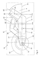
- FIG. 1 a first inventive grid-independent operable angle grinder 10 is shown, on which a (in the FIG. 1 only indicated) disc-shaped cutting or grinding tool 12 is attachable, which is drivable via a arranged in a housing 11 drive unit.
- the separating or grinding tool 12 can be fixed to a drive spindle 13, which emerges from the housing 11 on a housing flange 16.
- a protective hood 17 (only indicated) can be arranged on the housing 11, via which the separating or grinding tool 12 can be at least partially covered.
- the Housing 11 has, in addition to the housing flange 16, which receives a gear 19 of the drive unit, along with a first axis A1 extending first housing portion 14, which houses a motor 18 of the drive unit, and a along a second axis A2 extending further housing portion 15 a battery holder 25 on.
- an electrical energy store in the form of a rechargeable battery 30 is detachably received in the battery receptacle 25, wherein the rechargeable battery 30 runs with its longitudinal extent along the second axis A2.
- the further housing portion 15 is angled away from the first housing portion 14, so that the axes A1 and A2 are at an angle [alpha] to each other, which in the in FIG. 1 represented angle grinder amounts to 15 °.
- the angle grinder 10 further has a handle 20 which is arranged with a first end 21 on the first housing portion 14 and a second end 22 on the other housing portion 15 and thereby extends in a plane defined by the axes A1 and A2 plane E.
- the handle 20 is formed bridge-like and extends within a range which is spanned in the gusset between the first housing portion 14 and the further housing portion 15.
- a handle portion 23 is arranged at which a switch 24 for turning on and off the angle grinder 10 is located.
- the handle 20 is at least with a handle portion 23 spaced from the housing 11.
- the grip region 23 is further spaced substantially vertically with its center Z from the first axis A1 and a resulting center of gravity FR of the angle grinder 10 (see dotted line 26 in FIG Fig. 1 ).
- the resulting center of gravity FR results from the different centers of gravity (F1, F2, F3 ...) angle grinder 10, so in particular from the first center of gravity F1 in the drive spindle 13 with the gear 19 and the cutting or grinding tool 12, the second Center of gravity F2 in the area of the motor 18 and the third center of gravity F3 in the area of the battery 30 located in the battery holder 30th
- FIG. 2 a further inventive angle grinder 10 is shown, which differs in particular from the previously described that the further housing portion 15 is made steeper with the battery holder 25 and the battery 30 relative to the first housing portion 14.
- the second axis A2 of the further housing portion 15 is at an angle of 60 ° to the first axis A1 of the first Housing section 14.
Landscapes
- Engineering & Computer Science (AREA)
- Mechanical Engineering (AREA)
- Finish Polishing, Edge Sharpening, And Grinding By Specific Grinding Devices (AREA)
- Grinding-Machine Dressing And Accessory Apparatuses (AREA)
Abstract
Description
- Die Erfindung betrifft eine akkubetriebene Winkelschleifmaschine zum Antrieb von Trenn- oder Schleifscheiben.
- Derartige Winkelschleifmaschinen, weisen ein kreisscheibenförmiges Trenn- oder Schleifwerkzeug auf, das im Betrieb rotiert und z. B. zum Erzeugen von Schnitten in Untergründen oder zum Schleifen von Oberflächen dient. Das Trenn- oder Schleifwerkzeug wird dabei umfänglich zumindest bereichsweise von einer Schutzhaube abgedeckt.
- Aus der
DE 100 39 777 A1 ist ein als Winkelschleifer ausgebildetes batteriegespeistes Elektrowerkzeug bekannt, welches ein längliches Maschinengehäuse aufweist. Das Maschinengehäuse weist einen länglichen, etwa stabförmigen Gehäuseteil mit enthaltenem elektrischen Antriebsmotor und mit einem Endteil auf, an dem eine endseitige Anschlussfläche mit Einsteckaufnahme für die auswechselbare Anbringung eines Akkumulatorpakets vorgesehen ist, das mit einem Anschlussteil versehen ist, der zur Anlage an der Anschlussfläche eine dieser zugeordnete Anlagefläche und einen in die Einsteckaufnahme eingreifenden Einsteckteil aufweist. Der Endteil ist in Bezug auf den Gehäuseteil aus der Längserstreckungsrichtung heraus zu einer Seite hin abgeknickt. - Von Nachteil bei dieser bekannten Winkelschleifmaschine ist zum einen, dass das den Motor umgebende Gehäuse als Handgriff dient, der einen relativ grossen Durchmesser aufweist und entsprechend sperrig zu greifen ist. Ferner ist die Gewichtsverteilung für die am Gehäuseteil angreifende Hand eines Anwenders auf Grund der vorhandenen verschiedenen Einzelschwerpunkte (z. B. am Akkumulatorpaket, am Motor und am Werkzeug) ungünstig und führt zu grossen ggf. auf das Handgelenk des Anwenders wirkenden Momenten.
- Der vorliegenden Erfindung liegt die Aufgabe zugrunde, eine Winkelschleifmaschine bereitzustellen, die die genannten Nachteile vermeidet und die konstruktiv einfach ausgebildet ist.
- Erfindungsgemäss wird die Aufgabe durch die in Anspruch 1 genannten Massnahmen gelöst. Demnach weist die Winkelschleifmaschine einen Handgriff auf, der mit einem ersten Ende am ersten Gehäuseabschnitt und mit einem zweiten Ende am weiteren Gehäuseabschnitt angeordnet ist, wodurch eine leicht handhabbare und durch das abgewinkelte Gehäuse gleichzeitig kurze Winkelschleifmaschine geschaffen wird.
- Vorteilhaft liegt der Winkel zwischen der Achse des ersten Gehäuseabschnitts und der Achse des weiteren Gehäuseabschnitts in einem Bereich zwischen 10° und 65°, wodurch beide Gehäuseabschnitte über den Handgriff verbunden werden können, ohne dass Konturen des weiteren Gehäuseabschnitts vom Anwender als störend empfunden werden.
- Die Winkelschleifmaschine weist einen sich aus verschiedenen Schwerpunktzentren ergebenden resultierenden Massenschwerpunkt auf, der in der ersten Achse liegt, wobei ein Griffbereich des Handgriffs in Bezug auf die erste Achse vorteilhaft senkrecht beabstandet von dem resultierenden Massenschwerpunkt ist. Hierdurch ergibt sich ein ausbalanciertes Gerät, bei dessen Betrieb kaum ein Moment auf das Handgelenk einer den Hangriff haltenden Hand wirkt.
- Die Erfindung wird nachstehend anhand mehrerer Ausführungsbeispiele näher erläutert. Es zeigen:
- Fig. 1
- eine erfindungsgemässe Winkelschleifmaschine in seitlicher Ansicht,
- Fig. 2
- eine weitere erfindungsgemässe Winkelschleifmaschine in seitlicher Ansicht.
- Gleiche Bauteile sind in den Figuren und der nachfolgenden Beschreibung mit gleichen Bezugszeichen versehen.
- In
Figur 1 ist eine erste erfindungsgemässe netzunabhängig betreibbare Winkelschleifmaschine 10 dargestellt, an der ein (in derFigur 1 nur angedeutetes) scheibenförmiges Trenn- oder Schleifwerkzeug 12 anbringbar ist, welches über eine in einem Gehäuse 11 angeordnete Antriebseinheit antreibbar ist. Das Trenn- oder Schleifwerkzeug 12 ist dazu an einer Antriebsspindel 13 festlegbar, die an einem Gehäuseflansch 16 aus dem Gehäuse 11 austritt. Für das Trenn- oder Schleifwerkzeug 12 kann ferner eine Schutzhaube 17 (nur angedeutet) an dem Gehäuse 11 angeordnet sein, über die das Trenn- oder Schleifwerkzeug 12 zumindest teilweise abdeckbar ist. Das Gehäuse 11 weist zusätzlich zu dem Gehäuseflansch 16, der ein Getriebe 19 der Antriebseinheit aufnimmt, einen sich entlang einer ersten Achse A1 erstreckenden ersten Gehäuseabschnitt 14, der einen Motor 18 der Antriebseinheit beherbergt, und einen sich entlang einer zweiten Achse A2 erstreckenden weiteren Gehäuseabschnitt 15 mit einer Akkuaufnahme 25 auf. InFigur 1 ist in der Akkuaufnahme 25 ein elektrischer Energiespeicher in Form eines Akkus 30 lösbar aufgenommen, wobei der Akku 30 mit seiner Längserstreckung entlang der zweiten Achse A2 verläuft. Der weitere Gehäuseabschnitt 15 ist von dem ersten Gehäuseabschnitt 14 abgewinkelt, so dass die Achsen A1 und A2 in einem Winkel [alpha] zueinander liegen, der sich bei der inFigur 1 dargestellten Winkelschleifmaschine auf 15° beläuft. - Die Winkelschleifmaschine 10 weist ferner einen Handgriff 20 auf, der mit einem ersten Ende 21 am ersten Gehäuseabschnitt 14 und mit einem zweiten Ende 22 am weiteren Gehäuseabschnitt 15 angeordnet ist und dabei in einer durch die Achsen A1 und A2 definierten Ebene E verläuft. Der Handgriff 20 ist brückenartig ausgebildet und erstreckt sich innerhalb eines Bereichs, der im Zwickel zwischen dem ersten Gehäuseabschnitt 14 und dem weiteren Gehäuseabschnitt 15 aufgespannt wird.
- An dem Handgriff 20 ist ein Griffbereich 23 angeordnet an dem sich ein Schalter 24 zum Anund Ausschalten der Winkelschleifmaschine 10 befindet. Der Handgriff 20 ist dabei zumindest mit einem Griffbereich 23 vom Gehäuse 11 beabstandet. Der Griffbereich 23 ist ferner mit seinem Zentrum Z im Wesentlichen senkrecht beabstandet von der ersten Achse A1 und einem auf dieser liegenden resultierenden Massenschwerpunkt FR der Winkelschleifmaschine 10 (siehe punktiert angedeutete Linie 26 in
Fig. 1 ). Der resultierende Massenschwerpunkt FR ergibt sich dabei aus den verschiedenen Schwerpunktzentren (F1, F2, F3...) Winkelschleifmaschine 10, so insbesondere aus dem ersten Schwerpunktzentrum F1 im Bereich der Antriebsspindel 13 mit dem Getriebe 19 und dem Trenn- oder Schleifwerkzeug 12, dem zweiten Schwerpunktzentrum F2 im Bereich des Motors 18 und dem dritten Schwerpunktzentrum F3 im Bereich des in der Akkuaufnahme 25 befindlichen Akkus 30. - In
Figur 2 ist eine weitere erfindungsgemässe Winkelschleifmaschine 10 dargestellt, die sich insbesondere dadurch von der vorhergehend beschriebenen unterscheidet, dass der weitere Gehäuseabschnitt 15 mit der Akkuaufnahme 25 und dem Akku 30 gegenüber dem ersten Gehäuseabschnitt 14 steiler angestellt ist. So liegt die zweite Achse A2 des weiteren Gehäuseabschnitts 15 in einem Winkel von 60° zur ersten Achse A1 des ersten Gehäuseabschnitts 14. Wegen nachfolgend nicht erwähnter Bauteile und deren Funktion wird vollumfänglich auf die vorhergehende Beschreibung zuFigur 1 Bezug genommen.
Claims (3)
- Winkelschleifmaschine zum Betrieb eines Trenn- oder Schleifwerkzeugs (12), mit einem Gehäuse (11), das einen entlang einer ersten Achse (A1) verlaufenden ersten Gehäuseabschnitt (14), in dem ein Motor (18) angeordnet ist, und das einen entlang einer zweiten Achse (A2) verlaufenden weiteren Gehäuseabschnitt (15) mit einer Akkuaufnahme (25) aufweist, wobei die Achsen (A1, A2) in einem Winkel ([alpha]) zueinander verlaufen,
gekennzeichnet durch
einen Handgriff (20) der mit einem ersten Ende (21) am ersten Gehäuseabschnitt (14) und mit einem zweiten Ende (22) am weiteren Gehäuseabschnitt (15) angeordnet ist. - Winkelschleifmaschine nach Anspruch 1, dadurch gekennzeichnet, dass der Winkel ([alpha]) zwischen der ersten Achse (A1) und der zweiten Achse (A2) in einem Bereich zwischen 10° und 65° liegt.
- Winkelschleifmaschine nach Anspruch 1 oder 2, gekennzeichnet durch einen sich aus verschiedenen Schwerpunktzentren (F1, F2, F3) ergebenden resultierenden Massenschwerpunkt (FR), der in der ersten Achse (A1) liegt, wobei ein Griffbereich (23) des Handgriffs (20) in Bezug auf die erste Achse (A1) senkrecht beabstandet von dem resultierenden Massenschwerpunkt (FR) ist.
Applications Claiming Priority (1)
| Application Number | Priority Date | Filing Date | Title |
|---|---|---|---|
| DE102008042601A DE102008042601A1 (de) | 2008-10-03 | 2008-10-03 | Akkubetriebene Winkelschleifmaschine |
Publications (2)
| Publication Number | Publication Date |
|---|---|
| EP2172305A1 true EP2172305A1 (de) | 2010-04-07 |
| EP2172305B1 EP2172305B1 (de) | 2014-01-01 |
Family
ID=41527838
Family Applications (1)
| Application Number | Title | Priority Date | Filing Date |
|---|---|---|---|
| EP09171299.2A Active EP2172305B1 (de) | 2008-10-03 | 2009-09-25 | Akkubetriebene Winkelschleifmaschine |
Country Status (5)
| Country | Link |
|---|---|
| US (1) | US8251782B2 (de) |
| EP (1) | EP2172305B1 (de) |
| JP (1) | JP5502418B2 (de) |
| CN (1) | CN101712134A (de) |
| DE (1) | DE102008042601A1 (de) |
Cited By (2)
| Publication number | Priority date | Publication date | Assignee | Title |
|---|---|---|---|---|
| WO2015032564A1 (de) * | 2013-09-03 | 2015-03-12 | Robert Bosch Gmbh | Schleifmaschinengehäusevorrichtung |
| WO2023066717A1 (de) * | 2021-10-22 | 2023-04-27 | Robert Bosch Gmbh | Gehäusevorrichtung für eine handwerkzeugmaschine und handwerkzeugmaschine mit der gehäusevorrichtung |
Families Citing this family (7)
| Publication number | Priority date | Publication date | Assignee | Title |
|---|---|---|---|---|
| DE202009001437U1 (de) * | 2009-01-29 | 2010-07-01 | C. & E. Fein Gmbh | Kraftgetriebenes Handwerkzeug |
| DE102011085506A1 (de) * | 2011-10-31 | 2013-05-02 | Robert Bosch Gmbh | Aufhängevorrichtung für eine Handwerkzeugmaschine |
| DE102012111990A1 (de) * | 2012-12-07 | 2014-06-12 | Flex-Elektrowerkzeuge Gmbh | Handgehaltene Schleifmaschine |
| CN108687399A (zh) * | 2017-04-10 | 2018-10-23 | 南京德朔实业有限公司 | 手持式切割工具 |
| DE102021211953A1 (de) | 2021-10-22 | 2023-04-27 | Robert Bosch Gesellschaft mit beschränkter Haftung | Handwerkzeugmaschine und Handwerkzeugmaschinensystem mit der Handwerkzeugmaschine |
| DE102021211951A1 (de) | 2021-10-22 | 2023-04-27 | Robert Bosch Gesellschaft mit beschränkter Haftung | Gehäusevorrichtung für eine Handwerkzeugmaschine, Handwerkzeugmaschine mit der Gehäusevorrichtung und Handwerkzeugmaschinensystem mit der Handwerkzeugmaschine |
| CN116673842A (zh) * | 2023-05-19 | 2023-09-01 | 浙江科技学院 | 一种打磨喷涂设备 |
Citations (7)
| Publication number | Priority date | Publication date | Assignee | Title |
|---|---|---|---|---|
| DE3502449A1 (de) * | 1984-02-08 | 1985-08-08 | Robert Bosch Gmbh, 7000 Stuttgart | Elektropneumatischer bohr- und/oder schlaghammer mit batteriegespeistem antriebsmotor |
| DE20111644U1 (de) * | 2001-07-13 | 2001-10-18 | Paulke, Gabor, 24118 Kiel | Bohrmaschine für Netz- und Akkubetrieb |
| WO2002014029A1 (de) * | 2000-08-16 | 2002-02-21 | Robert Bosch Gmbh | Batteriegespeistes elektrowerkzeug |
| WO2003047818A1 (de) * | 2001-11-30 | 2003-06-12 | Robert Bosch Gmbh | Akku-handwerkzeugmaschine |
| DE20318570U1 (de) * | 2003-12-01 | 2004-04-29 | Hess, Markus, Dr. | Griff für ein handgeführtes Arbeitsgerät |
| US20070240892A1 (en) * | 2005-11-04 | 2007-10-18 | Black & Decker Inc. | Cordless outdoor power tool system |
| US7310879B1 (en) * | 2006-07-27 | 2007-12-25 | Robert Bosch Gmbh | Cutting attachment having an adjustable foot for rotary hand tools |
Family Cites Families (14)
| Publication number | Priority date | Publication date | Assignee | Title |
|---|---|---|---|---|
| US4158246A (en) * | 1977-09-07 | 1979-06-19 | Disston, Inc. | Portable cordless scrubber |
| JPS5516836U (de) * | 1978-07-18 | 1980-02-02 | ||
| JPS60153751U (ja) * | 1984-03-23 | 1985-10-14 | 神鋼電機株式会社 | 携帯用動力グラインダ− |
| JPH0247158U (de) * | 1988-09-27 | 1990-03-30 | ||
| US4967516A (en) * | 1989-12-13 | 1990-11-06 | Ryobi Motor Products Corp. | Debris collection system for a surface treating tool |
| DE19512262C2 (de) * | 1995-03-24 | 2003-07-31 | Black & Decker Inc | Handgeführter, motorgetriebener Hobel |
| US6161293A (en) * | 1998-08-14 | 2000-12-19 | One World Technologies, Inc. | Battery powered circular saw |
| DE19924547A1 (de) * | 1999-05-28 | 2000-11-30 | Bosch Gmbh Robert | Handwerkzeugmaschine mit Staubabsaugung |
| DE29922108U1 (de) * | 1999-12-16 | 2000-02-17 | Hilti Ag, Schaan | Handgeführtes Schleifgerät |
| DE10134000B4 (de) * | 2001-07-12 | 2004-09-02 | Gabor Paulke | Bohrmaschine für Netz- und Akkubetrieb |
| DE10145040A1 (de) * | 2001-09-13 | 2003-04-03 | Bosch Gmbh Robert | Handwerkzeugmaschine mit Staubabsaugung |
| DE20318670U1 (de) | 2003-12-03 | 2004-04-15 | Festerling, Jürgen | Stufen-Komposter |
| CN2882922Y (zh) * | 2006-01-27 | 2007-03-28 | 苏州宝时得电动工具有限公司 | 手持式工具 |
| JP2008264935A (ja) * | 2007-04-20 | 2008-11-06 | Makita Corp | 手持ち工具のハンドル |
-
2008
- 2008-10-03 DE DE102008042601A patent/DE102008042601A1/de not_active Withdrawn
-
2009
- 2009-09-25 EP EP09171299.2A patent/EP2172305B1/de active Active
- 2009-09-29 CN CN200910204453A patent/CN101712134A/zh active Pending
- 2009-09-30 US US12/587,055 patent/US8251782B2/en active Active
- 2009-10-01 JP JP2009229385A patent/JP5502418B2/ja active Active
Patent Citations (8)
| Publication number | Priority date | Publication date | Assignee | Title |
|---|---|---|---|---|
| DE3502449A1 (de) * | 1984-02-08 | 1985-08-08 | Robert Bosch Gmbh, 7000 Stuttgart | Elektropneumatischer bohr- und/oder schlaghammer mit batteriegespeistem antriebsmotor |
| WO2002014029A1 (de) * | 2000-08-16 | 2002-02-21 | Robert Bosch Gmbh | Batteriegespeistes elektrowerkzeug |
| DE10039777A1 (de) | 2000-08-16 | 2002-02-28 | Bosch Gmbh Robert | Batteriegespeistes Elektrowerkzeug |
| DE20111644U1 (de) * | 2001-07-13 | 2001-10-18 | Paulke, Gabor, 24118 Kiel | Bohrmaschine für Netz- und Akkubetrieb |
| WO2003047818A1 (de) * | 2001-11-30 | 2003-06-12 | Robert Bosch Gmbh | Akku-handwerkzeugmaschine |
| DE20318570U1 (de) * | 2003-12-01 | 2004-04-29 | Hess, Markus, Dr. | Griff für ein handgeführtes Arbeitsgerät |
| US20070240892A1 (en) * | 2005-11-04 | 2007-10-18 | Black & Decker Inc. | Cordless outdoor power tool system |
| US7310879B1 (en) * | 2006-07-27 | 2007-12-25 | Robert Bosch Gmbh | Cutting attachment having an adjustable foot for rotary hand tools |
Cited By (3)
| Publication number | Priority date | Publication date | Assignee | Title |
|---|---|---|---|---|
| WO2015032564A1 (de) * | 2013-09-03 | 2015-03-12 | Robert Bosch Gmbh | Schleifmaschinengehäusevorrichtung |
| US10350727B2 (en) | 2013-09-03 | 2019-07-16 | Robert Bosch Gmbh | Sanding machine housing device |
| WO2023066717A1 (de) * | 2021-10-22 | 2023-04-27 | Robert Bosch Gmbh | Gehäusevorrichtung für eine handwerkzeugmaschine und handwerkzeugmaschine mit der gehäusevorrichtung |
Also Published As
| Publication number | Publication date |
|---|---|
| US20100087127A1 (en) | 2010-04-08 |
| CN101712134A (zh) | 2010-05-26 |
| DE102008042601A1 (de) | 2010-04-08 |
| JP2010089253A (ja) | 2010-04-22 |
| EP2172305B1 (de) | 2014-01-01 |
| JP5502418B2 (ja) | 2014-05-28 |
| US8251782B2 (en) | 2012-08-28 |
Similar Documents
| Publication | Publication Date | Title |
|---|---|---|
| EP2172305B1 (de) | Akkubetriebene Winkelschleifmaschine | |
| EP2077924B1 (de) | Elektrische schere | |
| EP1844646B1 (de) | Heckenschere | |
| EP1620233B1 (de) | Elektrische handwerkzeugmaschine mit akkupack | |
| DE69709527T2 (de) | Batteriebetriebener Fadenschneider | |
| DE10141454A1 (de) | Batteriebetriebene Kreissäge | |
| EP3962699B1 (de) | Schutzvorrichtung für ein werkzeuggerät, sowie system, das eine schutzvorrichtung und ein werkzeuggerät umfasst | |
| DE112013006573B4 (de) | Handgehaltene elektrische Schneidvorrichtung | |
| EP1318896B1 (de) | Batteriegespeistes elektrowerkzeug | |
| DE102010042605A1 (de) | Arbeitswerkzeug, insbesondere Elektrowerkzeug | |
| DE112012005687T5 (de) | Kraftwerkzeug | |
| DE202018100760U1 (de) | Zweihändig bedienbare Schleifmaschine | |
| DE102013200576A1 (de) | Handwerkzeugmaschine mit einem ergonomischen Handgriff | |
| DE202016103421U1 (de) | Schneidwerkzeug, insbesondere Elektrokreissäge | |
| EP3456197B1 (de) | Unkraut-fugenfräse | |
| DE102018109264A1 (de) | Elektrisches Gerät | |
| DE102014100940A1 (de) | Selbstausrichtende Sandpapierschleifmaschine | |
| EP4619193A1 (de) | Schutzvorrichtung, akkuschutzelement, portables arbeitsgerät und verfahren zumindest zu einem schutz eines akkumulators | |
| DE102019117812B3 (de) | Drehwerkzeug-Handmaschine | |
| DE102018215646A1 (de) | Elektromaschine | |
| DE202018103045U1 (de) | Aufsatz auf eine Handwerkzeugmaschine | |
| EP4183518B1 (de) | Werkzeugmaschine mit einem längs zu einer schneidachse angeordneten motor | |
| EP0232761A2 (de) | Gerät zum Behandeln von Oberflächen od.dgl. | |
| DE10210069B4 (de) | Vorrichtung zur Bearbeitung von Schweißelektroden mit einer Schleifscheibe | |
| DE9215720U1 (de) | Sanitärbürste |
Legal Events
| Date | Code | Title | Description |
|---|---|---|---|
| PUAI | Public reference made under article 153(3) epc to a published international application that has entered the european phase |
Free format text: ORIGINAL CODE: 0009012 |
|
| AK | Designated contracting states |
Kind code of ref document: A1 Designated state(s): AT BE BG CH CY CZ DE DK EE ES FI FR GB GR HR HU IE IS IT LI LT LU LV MC MK MT NL NO PL PT RO SE SI SK SM TR |
|
| 17P | Request for examination filed |
Effective date: 20101007 |
|
| 17Q | First examination report despatched |
Effective date: 20110426 |
|
| GRAP | Despatch of communication of intention to grant a patent |
Free format text: ORIGINAL CODE: EPIDOSNIGR1 |
|
| INTG | Intention to grant announced |
Effective date: 20130809 |
|
| GRAS | Grant fee paid |
Free format text: ORIGINAL CODE: EPIDOSNIGR3 |
|
| GRAA | (expected) grant |
Free format text: ORIGINAL CODE: 0009210 |
|
| AK | Designated contracting states |
Kind code of ref document: B1 Designated state(s): AT BE BG CH CY CZ DE DK EE ES FI FR GB GR HR HU IE IS IT LI LT LU LV MC MK MT NL NO PL PT RO SE SI SK SM TR |
|
| REG | Reference to a national code |
Ref country code: GB Ref legal event code: FG4D Free format text: NOT ENGLISH |
|
| REG | Reference to a national code |
Ref country code: CH Ref legal event code: EP |
|
| REG | Reference to a national code |
Ref country code: IE Ref legal event code: FG4D Free format text: LANGUAGE OF EP DOCUMENT: GERMAN |
|
| REG | Reference to a national code |
Ref country code: DE Ref legal event code: R096 Ref document number: 502009008602 Country of ref document: DE Effective date: 20140213 |
|
| REG | Reference to a national code |
Ref country code: AT Ref legal event code: REF Ref document number: 647382 Country of ref document: AT Kind code of ref document: T Effective date: 20140215 |
|
| REG | Reference to a national code |
Ref country code: NL Ref legal event code: VDEP Effective date: 20140101 |
|
| REG | Reference to a national code |
Ref country code: LT Ref legal event code: MG4D |
|
| PG25 | Lapsed in a contracting state [announced via postgrant information from national office to epo] |
Ref country code: LT Free format text: LAPSE BECAUSE OF FAILURE TO SUBMIT A TRANSLATION OF THE DESCRIPTION OR TO PAY THE FEE WITHIN THE PRESCRIBED TIME-LIMIT Effective date: 20140101 Ref country code: IS Free format text: LAPSE BECAUSE OF FAILURE TO SUBMIT A TRANSLATION OF THE DESCRIPTION OR TO PAY THE FEE WITHIN THE PRESCRIBED TIME-LIMIT Effective date: 20140501 |
|
| PG25 | Lapsed in a contracting state [announced via postgrant information from national office to epo] |
Ref country code: PT Free format text: LAPSE BECAUSE OF FAILURE TO SUBMIT A TRANSLATION OF THE DESCRIPTION OR TO PAY THE FEE WITHIN THE PRESCRIBED TIME-LIMIT Effective date: 20140502 Ref country code: NL Free format text: LAPSE BECAUSE OF FAILURE TO SUBMIT A TRANSLATION OF THE DESCRIPTION OR TO PAY THE FEE WITHIN THE PRESCRIBED TIME-LIMIT Effective date: 20140101 Ref country code: CY Free format text: LAPSE BECAUSE OF FAILURE TO SUBMIT A TRANSLATION OF THE DESCRIPTION OR TO PAY THE FEE WITHIN THE PRESCRIBED TIME-LIMIT Effective date: 20140101 Ref country code: SE Free format text: LAPSE BECAUSE OF FAILURE TO SUBMIT A TRANSLATION OF THE DESCRIPTION OR TO PAY THE FEE WITHIN THE PRESCRIBED TIME-LIMIT Effective date: 20140101 Ref country code: FI Free format text: LAPSE BECAUSE OF FAILURE TO SUBMIT A TRANSLATION OF THE DESCRIPTION OR TO PAY THE FEE WITHIN THE PRESCRIBED TIME-LIMIT Effective date: 20140101 Ref country code: ES Free format text: LAPSE BECAUSE OF FAILURE TO SUBMIT A TRANSLATION OF THE DESCRIPTION OR TO PAY THE FEE WITHIN THE PRESCRIBED TIME-LIMIT Effective date: 20140101 |
|
| PG25 | Lapsed in a contracting state [announced via postgrant information from national office to epo] |
Ref country code: HR Free format text: LAPSE BECAUSE OF FAILURE TO SUBMIT A TRANSLATION OF THE DESCRIPTION OR TO PAY THE FEE WITHIN THE PRESCRIBED TIME-LIMIT Effective date: 20140101 Ref country code: LV Free format text: LAPSE BECAUSE OF FAILURE TO SUBMIT A TRANSLATION OF THE DESCRIPTION OR TO PAY THE FEE WITHIN THE PRESCRIBED TIME-LIMIT Effective date: 20140101 |
|
| REG | Reference to a national code |
Ref country code: DE Ref legal event code: R097 Ref document number: 502009008602 Country of ref document: DE |
|
| PG25 | Lapsed in a contracting state [announced via postgrant information from national office to epo] |
Ref country code: EE Free format text: LAPSE BECAUSE OF FAILURE TO SUBMIT A TRANSLATION OF THE DESCRIPTION OR TO PAY THE FEE WITHIN THE PRESCRIBED TIME-LIMIT Effective date: 20140101 Ref country code: DK Free format text: LAPSE BECAUSE OF FAILURE TO SUBMIT A TRANSLATION OF THE DESCRIPTION OR TO PAY THE FEE WITHIN THE PRESCRIBED TIME-LIMIT Effective date: 20140101 Ref country code: RO Free format text: LAPSE BECAUSE OF FAILURE TO SUBMIT A TRANSLATION OF THE DESCRIPTION OR TO PAY THE FEE WITHIN THE PRESCRIBED TIME-LIMIT Effective date: 20140101 Ref country code: CZ Free format text: LAPSE BECAUSE OF FAILURE TO SUBMIT A TRANSLATION OF THE DESCRIPTION OR TO PAY THE FEE WITHIN THE PRESCRIBED TIME-LIMIT Effective date: 20140101 |
|
| PLBE | No opposition filed within time limit |
Free format text: ORIGINAL CODE: 0009261 |
|
| STAA | Information on the status of an ep patent application or granted ep patent |
Free format text: STATUS: NO OPPOSITION FILED WITHIN TIME LIMIT |
|
| PG25 | Lapsed in a contracting state [announced via postgrant information from national office to epo] |
Ref country code: SK Free format text: LAPSE BECAUSE OF FAILURE TO SUBMIT A TRANSLATION OF THE DESCRIPTION OR TO PAY THE FEE WITHIN THE PRESCRIBED TIME-LIMIT Effective date: 20140101 Ref country code: PL Free format text: LAPSE BECAUSE OF FAILURE TO SUBMIT A TRANSLATION OF THE DESCRIPTION OR TO PAY THE FEE WITHIN THE PRESCRIBED TIME-LIMIT Effective date: 20140101 |
|
| 26N | No opposition filed |
Effective date: 20141002 |
|
| REG | Reference to a national code |
Ref country code: DE Ref legal event code: R097 Ref document number: 502009008602 Country of ref document: DE Effective date: 20141002 |
|
| PG25 | Lapsed in a contracting state [announced via postgrant information from national office to epo] |
Ref country code: LU Free format text: LAPSE BECAUSE OF FAILURE TO SUBMIT A TRANSLATION OF THE DESCRIPTION OR TO PAY THE FEE WITHIN THE PRESCRIBED TIME-LIMIT Effective date: 20140925 Ref country code: MC Free format text: LAPSE BECAUSE OF FAILURE TO SUBMIT A TRANSLATION OF THE DESCRIPTION OR TO PAY THE FEE WITHIN THE PRESCRIBED TIME-LIMIT Effective date: 20140101 |
|
| PG25 | Lapsed in a contracting state [announced via postgrant information from national office to epo] |
Ref country code: SI Free format text: LAPSE BECAUSE OF FAILURE TO SUBMIT A TRANSLATION OF THE DESCRIPTION OR TO PAY THE FEE WITHIN THE PRESCRIBED TIME-LIMIT Effective date: 20140101 |
|
| REG | Reference to a national code |
Ref country code: IE Ref legal event code: MM4A |
|
| PG25 | Lapsed in a contracting state [announced via postgrant information from national office to epo] |
Ref country code: BE Free format text: LAPSE BECAUSE OF NON-PAYMENT OF DUE FEES Effective date: 20140930 |
|
| PG25 | Lapsed in a contracting state [announced via postgrant information from national office to epo] |
Ref country code: IE Free format text: LAPSE BECAUSE OF NON-PAYMENT OF DUE FEES Effective date: 20140925 |
|
| REG | Reference to a national code |
Ref country code: AT Ref legal event code: MM01 Ref document number: 647382 Country of ref document: AT Kind code of ref document: T Effective date: 20140925 |
|
| PG25 | Lapsed in a contracting state [announced via postgrant information from national office to epo] |
Ref country code: AT Free format text: LAPSE BECAUSE OF NON-PAYMENT OF DUE FEES Effective date: 20140925 |
|
| PG25 | Lapsed in a contracting state [announced via postgrant information from national office to epo] |
Ref country code: SM Free format text: LAPSE BECAUSE OF FAILURE TO SUBMIT A TRANSLATION OF THE DESCRIPTION OR TO PAY THE FEE WITHIN THE PRESCRIBED TIME-LIMIT Effective date: 20140101 Ref country code: NO Free format text: LAPSE BECAUSE OF FAILURE TO SUBMIT A TRANSLATION OF THE DESCRIPTION OR TO PAY THE FEE WITHIN THE PRESCRIBED TIME-LIMIT Effective date: 20140401 |
|
| PG25 | Lapsed in a contracting state [announced via postgrant information from national office to epo] |
Ref country code: IT Free format text: LAPSE BECAUSE OF FAILURE TO SUBMIT A TRANSLATION OF THE DESCRIPTION OR TO PAY THE FEE WITHIN THE PRESCRIBED TIME-LIMIT Effective date: 20140101 Ref country code: BG Free format text: LAPSE BECAUSE OF FAILURE TO SUBMIT A TRANSLATION OF THE DESCRIPTION OR TO PAY THE FEE WITHIN THE PRESCRIBED TIME-LIMIT Effective date: 20140101 Ref country code: MT Free format text: LAPSE BECAUSE OF FAILURE TO SUBMIT A TRANSLATION OF THE DESCRIPTION OR TO PAY THE FEE WITHIN THE PRESCRIBED TIME-LIMIT Effective date: 20140101 Ref country code: GR Free format text: LAPSE BECAUSE OF FAILURE TO SUBMIT A TRANSLATION OF THE DESCRIPTION OR TO PAY THE FEE WITHIN THE PRESCRIBED TIME-LIMIT Effective date: 20140402 |
|
| PG25 | Lapsed in a contracting state [announced via postgrant information from national office to epo] |
Ref country code: HU Free format text: LAPSE BECAUSE OF FAILURE TO SUBMIT A TRANSLATION OF THE DESCRIPTION OR TO PAY THE FEE WITHIN THE PRESCRIBED TIME-LIMIT; INVALID AB INITIO Effective date: 20090925 Ref country code: TR Free format text: LAPSE BECAUSE OF FAILURE TO SUBMIT A TRANSLATION OF THE DESCRIPTION OR TO PAY THE FEE WITHIN THE PRESCRIBED TIME-LIMIT Effective date: 20140101 |
|
| REG | Reference to a national code |
Ref country code: FR Ref legal event code: PLFP Year of fee payment: 8 |
|
| REG | Reference to a national code |
Ref country code: FR Ref legal event code: PLFP Year of fee payment: 9 |
|
| PG25 | Lapsed in a contracting state [announced via postgrant information from national office to epo] |
Ref country code: MK Free format text: LAPSE BECAUSE OF FAILURE TO SUBMIT A TRANSLATION OF THE DESCRIPTION OR TO PAY THE FEE WITHIN THE PRESCRIBED TIME-LIMIT Effective date: 20140101 |
|
| REG | Reference to a national code |
Ref country code: FR Ref legal event code: PLFP Year of fee payment: 10 |
|
| PGFP | Annual fee paid to national office [announced via postgrant information from national office to epo] |
Ref country code: FR Payment date: 20190927 Year of fee payment: 11 |
|
| PGFP | Annual fee paid to national office [announced via postgrant information from national office to epo] |
Ref country code: GB Payment date: 20190925 Year of fee payment: 11 |
|
| PGFP | Annual fee paid to national office [announced via postgrant information from national office to epo] |
Ref country code: CH Payment date: 20190919 Year of fee payment: 11 |
|
| REG | Reference to a national code |
Ref country code: CH Ref legal event code: PL |
|
| GBPC | Gb: european patent ceased through non-payment of renewal fee |
Effective date: 20200925 |
|
| PG25 | Lapsed in a contracting state [announced via postgrant information from national office to epo] |
Ref country code: FR Free format text: LAPSE BECAUSE OF NON-PAYMENT OF DUE FEES Effective date: 20200930 |
|
| PG25 | Lapsed in a contracting state [announced via postgrant information from national office to epo] |
Ref country code: CH Free format text: LAPSE BECAUSE OF NON-PAYMENT OF DUE FEES Effective date: 20200930 Ref country code: GB Free format text: LAPSE BECAUSE OF NON-PAYMENT OF DUE FEES Effective date: 20200925 Ref country code: LI Free format text: LAPSE BECAUSE OF NON-PAYMENT OF DUE FEES Effective date: 20200930 |
|
| PGFP | Annual fee paid to national office [announced via postgrant information from national office to epo] |
Ref country code: DE Payment date: 20240918 Year of fee payment: 16 |