EP2172176B1 - Inkubator mit Handeingriffstür - Google Patents
Inkubator mit Handeingriffstür Download PDFInfo
- Publication number
- EP2172176B1 EP2172176B1 EP20090008786 EP09008786A EP2172176B1 EP 2172176 B1 EP2172176 B1 EP 2172176B1 EP 20090008786 EP20090008786 EP 20090008786 EP 09008786 A EP09008786 A EP 09008786A EP 2172176 B1 EP2172176 B1 EP 2172176B1
- Authority
- EP
- European Patent Office
- Prior art keywords
- hand insertion
- latch
- incubator
- rotation
- door
- Prior art date
- Legal status (The legal status is an assumption and is not a legal conclusion. Google has not performed a legal analysis and makes no representation as to the accuracy of the status listed.)
- Not-in-force
Links
- 238000003780 insertion Methods 0.000 title claims description 187
- 230000037431 insertion Effects 0.000 title claims description 187
- 230000007246 mechanism Effects 0.000 claims description 63
- 238000012856 packing Methods 0.000 claims description 18
- 229920002379 silicone rubber Polymers 0.000 claims description 9
- 239000004945 silicone rubber Substances 0.000 claims description 9
- 230000006835 compression Effects 0.000 claims description 7
- 238000007906 compression Methods 0.000 claims description 7
- 125000006850 spacer group Chemical group 0.000 claims description 5
- 239000002250 absorbent Substances 0.000 claims description 4
- 239000000463 material Substances 0.000 claims description 4
- 230000005489 elastic deformation Effects 0.000 claims description 2
- 238000011282 treatment Methods 0.000 description 6
- 229920003002 synthetic resin Polymers 0.000 description 3
- 239000000057 synthetic resin Substances 0.000 description 3
- 230000004913 activation Effects 0.000 description 2
- 238000013459 approach Methods 0.000 description 1
- QVGXLLKOCUKJST-UHFFFAOYSA-N atomic oxygen Chemical compound [O] QVGXLLKOCUKJST-UHFFFAOYSA-N 0.000 description 1
- 230000036760 body temperature Effects 0.000 description 1
- 238000011109 contamination Methods 0.000 description 1
- 230000003247 decreasing effect Effects 0.000 description 1
- 239000003814 drug Substances 0.000 description 1
- 229940079593 drug Drugs 0.000 description 1
- 230000000694 effects Effects 0.000 description 1
- 238000004519 manufacturing process Methods 0.000 description 1
- 229910052760 oxygen Inorganic materials 0.000 description 1
- 239000001301 oxygen Substances 0.000 description 1
- 230000001012 protector Effects 0.000 description 1
- 239000012858 resilient material Substances 0.000 description 1
- 239000012780 transparent material Substances 0.000 description 1
Images


Classifications
-
- A—HUMAN NECESSITIES
- A61—MEDICAL OR VETERINARY SCIENCE; HYGIENE
- A61G—TRANSPORT, PERSONAL CONVEYANCES, OR ACCOMMODATION SPECIALLY ADAPTED FOR PATIENTS OR DISABLED PERSONS; OPERATING TABLES OR CHAIRS; CHAIRS FOR DENTISTRY; FUNERAL DEVICES
- A61G11/00—Baby-incubators; Couveuses
-
- A—HUMAN NECESSITIES
- A61—MEDICAL OR VETERINARY SCIENCE; HYGIENE
- A61G—TRANSPORT, PERSONAL CONVEYANCES, OR ACCOMMODATION SPECIALLY ADAPTED FOR PATIENTS OR DISABLED PERSONS; OPERATING TABLES OR CHAIRS; CHAIRS FOR DENTISTRY; FUNERAL DEVICES
- A61G11/00—Baby-incubators; Couveuses
- A61G11/009—Baby-incubators; Couveuses with hand insertion windows, e.g. in the walls
-
- E—FIXED CONSTRUCTIONS
- E05—LOCKS; KEYS; WINDOW OR DOOR FITTINGS; SAFES
- E05C—BOLTS OR FASTENING DEVICES FOR WINGS, SPECIALLY FOR DOORS OR WINDOWS
- E05C3/00—Fastening devices with bolts moving pivotally or rotatively
- E05C3/12—Fastening devices with bolts moving pivotally or rotatively with latching action
- E05C3/16—Fastening devices with bolts moving pivotally or rotatively with latching action with operating handle or equivalent member moving otherwise than rigidly with the latch
- E05C3/162—Fastening devices with bolts moving pivotally or rotatively with latching action with operating handle or equivalent member moving otherwise than rigidly with the latch the handle or member moving essentially towards or away of the plane of the wing or frame
-
- A—HUMAN NECESSITIES
- A61—MEDICAL OR VETERINARY SCIENCE; HYGIENE
- A61G—TRANSPORT, PERSONAL CONVEYANCES, OR ACCOMMODATION SPECIALLY ADAPTED FOR PATIENTS OR DISABLED PERSONS; OPERATING TABLES OR CHAIRS; CHAIRS FOR DENTISTRY; FUNERAL DEVICES
- A61G11/00—Baby-incubators; Couveuses
- A61G11/001—Baby-incubators; Couveuses with height-adjustable elements
- A61G11/003—Baby-incubators; Couveuses with height-adjustable elements height-adjustable heater
-
- A—HUMAN NECESSITIES
- A61—MEDICAL OR VETERINARY SCIENCE; HYGIENE
- A61G—TRANSPORT, PERSONAL CONVEYANCES, OR ACCOMMODATION SPECIALLY ADAPTED FOR PATIENTS OR DISABLED PERSONS; OPERATING TABLES OR CHAIRS; CHAIRS FOR DENTISTRY; FUNERAL DEVICES
- A61G11/00—Baby-incubators; Couveuses
- A61G11/005—Baby-incubators; Couveuses with movable walls, e.g. for accessing the inside, removable walls
-
- Y—GENERAL TAGGING OF NEW TECHNOLOGICAL DEVELOPMENTS; GENERAL TAGGING OF CROSS-SECTIONAL TECHNOLOGIES SPANNING OVER SEVERAL SECTIONS OF THE IPC; TECHNICAL SUBJECTS COVERED BY FORMER USPC CROSS-REFERENCE ART COLLECTIONS [XRACs] AND DIGESTS
- Y10—TECHNICAL SUBJECTS COVERED BY FORMER USPC
- Y10T—TECHNICAL SUBJECTS COVERED BY FORMER US CLASSIFICATION
- Y10T292/00—Closure fasteners
- Y10T292/08—Bolts
- Y10T292/0911—Hooked end
- Y10T292/0926—Spring projected
- Y10T292/0928—Operating means
- Y10T292/0934—Rigid
-
- Y—GENERAL TAGGING OF NEW TECHNOLOGICAL DEVELOPMENTS; GENERAL TAGGING OF CROSS-SECTIONAL TECHNOLOGIES SPANNING OVER SEVERAL SECTIONS OF THE IPC; TECHNICAL SUBJECTS COVERED BY FORMER USPC CROSS-REFERENCE ART COLLECTIONS [XRACs] AND DIGESTS
- Y10—TECHNICAL SUBJECTS COVERED BY FORMER USPC
- Y10T—TECHNICAL SUBJECTS COVERED BY FORMER US CLASSIFICATION
- Y10T292/00—Closure fasteners
- Y10T292/08—Bolts
- Y10T292/1043—Swinging
- Y10T292/1051—Spring projected
- Y10T292/1052—Operating means
- Y10T292/1061—Rigid
Definitions
- the present invention relates to an incubator that includes: a hand insertion window formed in a side of a newborn chamber; a hand insertion door that opens and closes the hand insertion window by rotation; and a latch mechanism that holds the hand insertion door in a closing position.
- An incubator has a newborn chamber to provide appropriate physiological environment for a newborn that cannot adjust its body temperature and others by itself. Substantially entire areas of the sides and top of a newborn chamber are formed from transparent members so that a newborn in the newborn chamber can be seen from the outside. Within the newborn chamber, not only temperature but also humidity, oxygen concentration and others are controlled. A treating person, however, such as a doctor or a nurse gives treatment to a newborn in a newborn chamber, when necessary. Therefore, for relatively simple treatments, hand insertion windows are formed in certain sides of the newborn chamber. Additionally, the incubator has a hand insertion door that opens and closes the hand insertion window by rotation, and a latch mechanism that holds the hand insertion door in a closing position.
- hand insertion windows are closed by hand insertion doors and that the hand insertion doors are held in their closing positions by their corresponding latch mechanisms.
- each hand insertion window has to be opened by rotating its hand insertion door to its opening position from its closing position.
- a treating person may have in its both hands a medical device, medical drug, or others for treating a newborn. Additionally, there may be a case where contamination of sterilized both hands has to be prevented.
- Patent Literatures 1 and 2 have a releasing member for releasing a latch mechanism such that the hand insertion window can easily be opened by only pressing the releasing member in a direction perpendicular to the corresponding side face of a newborn chamber with, for example, an elbow instead of a hand.
- a hand insertion window can be opened by only pressing each releasing member in a direction perpendicular to the corresponding side of a newborn chamber. Therefore, if a treating person or others leans on the releasing member or the releasing member comes into contact with a wall during conveyance of the incubator, the hand insertion window may be opened unintentionally. Furthermore, in the conventional incubators mentioned above, there can happen a state where, although a hand insertion door is almost in contact with a latch mechanism, this hand insertion door is not securely held in its closing position and, therefore, the corresponding hand insertion window is incompletely closed. If the hand insertion window is unintentionally opened or incompletely closed when a newborn is in the newborn chamber, the inside of the newborn chamber will deviate from appropriate physiological environment for the newborn, and there is the possibility that the physical condition of the newborn gets out of order.
- the hand insertion door can rotate freely while it is not held in its closing position by the latch mechanism. Additionally, also the latch mechanism is suddenly activated by urging force when it holds the hand insertion door in its closing position. For these reasons, the hand insertion door or latch mechanism may bump against another part of the incubator. Noise and vibration by impact resulting from this bump may put stress on a newborn in the newborn chamber, and there is the additional possibility that the physical condition of the newborn gets out of order. It is accordingly an object of the present invention to provide an incubator designed such that the physical condition of a newborn is less likely to get out of order though a hand insertion window can easily be opened by operation with, for example, an elbow instead of a hand.
- a latch in a latch mechanism has a spiral face that extends to at least part of the periphery of a rotation shaft that extends along a side of a newborn chamber.
- a releasing member in the latch mechanism presses the spiral face of the latch by movement along the side of the newborn chamber, and rotates the latch about the rotation shaft from a holding position to a releasing position for a hand insertion door. Accordingly, a hand insertion window can be opened by only pressing and moving the releasing member in the latch mechanism along the side of the newborn chamber.
- the releasing member in the latch mechanism has to be pressed along the side of the newborn chamber. Accordingly, even if a treating person or others leans on the releasing member or the releasing member comes into contact with a wall during conveyance of the incubator, the hand insertion window will not be opened. In addition, even if the latch in the latch mechanism rotates between the holding and releasing positions for the hand insertion door, the releasing member does not rotate, and therefore impact due to activation of the latch mechanism is less likely to occur.
- an opening mechanism comes into contact with the hand insertion door before the hand insertion window is closed.
- the opening mechanism urges the hand insertion door so as to rotate in the direction in which the hand insertion window is opened. Therefore, if the hand insertion window is not completely closed, the hand insertion window is opened, and it is easily aware that the hand insertion window is not closed. Accordingly, the hand insertion window is more likely to be again closed.
- a pressed portion, which is pressed by rotation of the hand insertion door, of the latch in the latch mechanism is made of impact-absorbent material. Accordingly, even if the hand insertion door bumps against the latch when the hand insertion door is rotated to close the hand insertion window, impact is less likely to occur.
- a braking mechanism brakes the rotation of the hand insertion door. Accordingly, the hand insertion door does not stop suddenly when the hand insertion window has completely been opened, and impact is less likely to occur when the hand insertion window has completely been opened.
- an urging member in the latch mechanism urges the latch so as to rotate the latch from the releasing position to the holding position. Accordingly, if the latch is only rotated to the releasing position, the latch rotates automatically from the releasing position to the holding position without being manually rotated from the releasing position to the holding position and holds the hand insertion door.
- a braking member in the latch mechanism brakes rotation of the latch. Accordingly, even if the latch rotates automatically from the releasing position to the holding position, impact is less likely to occur at the holding position.
- the hand insertion window can be opened by only pressing and moving the releasing member in the latch mechanism along the side of the newborn chamber. Accordingly, the hand insertion window can easily be opened by operation with, for example, an elbow instead of a hand. Additionally, even if a treating person or others leans on the releasing member or the releasing member comes into contact with a wall during conveyance of the incubator, the hand insertion window will not be opened. Therefore, the inside of the newborn chamber is less likely to deviate from appropriate physiological environment for a newborn. Furthermore, impact due to the activation of the latch mechanism is less likely to occur. Therefore, less stress is put on a newborn in the newborn chamber when the latch mechanism is activated. Accordingly, the physical condition of the newborn is less likely to get out of order.
- the hand insertion window is opened, and it is easily aware that the hand insertion window is not closed. Therefore, the hand insertion window is more likely to be again closed. Accordingly, the inside of the newborn chamber is less likely to deviate from appropriate physiological environment for a newborn, and physical condition of the newborn is less likely to get out of order.
- the hand insertion door does not stop suddenly when the hand insertion window has completely been opened, and impact is less likely to occur when the hand insertion window has completely been opened. Accordingly, less stress is put on the newborn in the newborn chamber when the hand insertion window is opened, and physical condition of the newborn is less likely to get out of order.
- the latch in the latch mechanism if the latch in the latch mechanism is only rotated to the releasing position, the latch rotates automatically from the releasing position to the holding position without being manually rotated from the releasing position to the holding position and holds the hand insertion door. Accordingly, it is easy to close the hand insertion window with the hand insertion door. Nevertheless, even if the latch rotates automatically from the releasing position to the holding position, impact is less likely to occur at the holding position. Accordingly, less stress is put on the newborn in the newborn chamber when the hand insertion window is opened, and physical condition of the newborn is less likely to get out of order.
- FIG. 1 to 11 there will be described one embodiment of the present invention applied to a switching type incubator capable of switching between a closed type and open type as required by lowering or raising a canopy of a newborn chamber.
- the present embodiment will be described according to the following list.
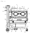
- Fig. 11 shows an incubator of the present embodiment in a closed type.
- wheels 13 and a support 14 are attached to a frame 12.
- a base 15 is supported on the support 14.
- a control mechanism (not shown) for temperature, humidity and others.
- Disposed on the base 15 is a newborn chamber 16.
- a drawer 17 for use as storage is attached to the underside of the base 15.
- Pedals 18 are also attached to the frame 12 in order to adjust the height of the base 15 or others along the support 14.
- a bed (not shown) is disposed in the newborn chamber 16. Formed in the sides of the newborn chamber 16 are: a pair of left and right treatment doors 21 which is located on the left and right sides of a newborn (not shown) lying on the bed; a foot end treatment door 22 which is located at the foot end; and a head end treatment wall 23 which is located at the head end.
- a pair of left and right posts 24 is also attached to the frame 12. Another post (not shown) is nested in the post 24. The other post is slidable within the post 24.
- a canopy 25 of the newborn chamber 16 and an infrared heater 26 are supported respectively by one and the other of the other left and right posts nested in posts 24. By sliding these other posts within the corresponding posts 24, the canopy 25 and infrared heater 26 can be raised or lowered independently.
- the canopy 25 is also made of transparent material. Attached also to the posts 24 is a protector 27 that prevents the infrared heater 26 from bumping against the wall (not shown) of a room.
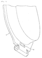
- the left and right treatment doors 21 each have an outer wall 31 and an inner wall 32 (see Fig. 9 ) that are transparent and form a double-wall structure.
- Each outer wall 31 and the corresponding inner wall 32 have: a pair of left and right hand insertion windows 33 (see Fig. 9 ); a pair of left and right hand insertion doors 34 for closing and opening the corresponding hand insertion windows 33; and latch mechanisms 35 for holding the corresponding hand insertion doors 34 in their closing positions for closing the corresponding hand insertion windows 33.
- Fig. 10 shows one of the pair of hand insertion doors 34 and the corresponding latch mechanism 35.
- a hand-insertion-door base plate 36 of annular shape and made of transparent rigid synthetic resin is fitted and screwed to the internal edge of the outer wall 31 of the hand insertion window 33 of the newborn chamber 16.
- the hand insertion door 34 is also made of a transparent rigid synthetic resin and has a dish-like shape.
- the hand insertion door 34 is supported diametrically opposite the latch mechanism 35 on the edge of the hand-insertion-door base plate 36.
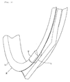
- the hand insertion door 34 is rotatable about a rotation shaft 37 between a closing position in which the hand insertion door 34 closes the hand insertion window 33 as shown in Figs. 9 and 10 and an opening position in which it opens the hand insertion window 33 as shown in Fig. 5 .
- the hand insertion door 34 is urged from the above-mentioned closing position toward the above-mentioned opening position by a helical coil spring 38 in which the rotation shaft 37 is inserted.
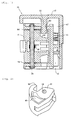
- Fig. 1 shows the latch mechanism 35 in Figs. 10 and 11 .
- the latch mechanism 35 includes a latch 41, a latch base plate 42, and a releasing member 43.
- the latch base plate 42 is fixed to the hand-insertion-door base plate 36.
- the latch 41 and the releasing member 43 are supported by the latch base plate 42.
- the latch 41 is rotatable about a rotation shaft 44 between a holding position in which the latch 41 holds the hand insertion door 34 in the closing position as shown in Figs. 9 and 10 and a releasing position in which it releases the holding as shown in Fig. 8 .
- a helical coil spring 45 in which the rotation shaft 44 is inserted, is interposed between the latch 41 and the latch base plate 42.
- the latch 41 is urged by the helical coil spring 45 from the releasing position to the holding position.
- the latch 41 has a spiral face 46 that extends to part of the periphery of the rotation shaft 44.
- a column 47 and a helical compression spring 51 interposed between the releasing member 43 and the latch base plate 42 are a column 47 and a helical compression spring 51.
- the releasing member 43 is urged by the helical compression spring 51 in a direction extending from the base 15 toward the canopy 25, that is, upward along the outer wall 31 of the newborn chamber 16.
- a projection 52 is formed integrally with the releasing member 43 so as to be parallel with the column 47 and the helical compression spring 51. This projection 52 extends to an area above the spiral face 46 through an opening 53 made in the latch base plate 42.
- the hand insertion door 34 is rotated against the urge applied from the helical coil spring 38.
- a tongue portion 54 which is the rotating leading-end of the hand insertion door 34, presses a pressed portion 55 of the latch 41 which is in the holding position.
- the latch 41 rotates about the rotation shaft 44 to the releasing position, as shown in Fig. 8 , against the urge applied from the helical coil spring 45.
- the releasing member 43 is pressed down in a direction extending from the canopy 25 toward the base 15, that is, downward along the outer wall 31 of the newborn chamber 16, against the urge of the releasing member 43.
- the urge of the releasing member 43 is applied from the helical compression spring 51 in a direction extending from the base 15 toward the canopy 25, that is, upward along the outer wall 31 of the newborn chamber 16.
- the latch 41 rotates about the rotation shaft 44 from the holding position to the releasing position against the urge applied from the helical coil spring 45. Consequently, the tongue portion 54 of the hand insertion door 34 is released from being held by the latch 41, and the hand insertion door 34 is rotated by the urge applied from the helical coil spring 38. Accordingly, the hand insertion door 34 opens the hand insertion window 33.
- the projection 52 of the releasing member 43 is moved upward through the opening 53 by the urge applied from the helical compression spring 51, and the projection 52 separates from the spiral face 46 of the latch 41 due to this upward movement. Accordingly, the latch 41 returns from the releasing position to the holding position by the urge applied from the helical coil spring 45.
- a packing 56 of annular shape and made of silicone rubber is fitted along the internal edge of the hand-insertion-door base plate 36.
- most of the portion of the packing 56 that is in contact with the hand insertion door 34 closing the hand insertion window 33 is a fin-shaped portion 57 but the portion of the packing 56 near the rotation shaft 37 of the hand insertion door 34 is a thicker portion 61.
- Disposed on the thicker portion 61 is a projection 62 that prevents the packing 56 from being erroneously attached.
- a recess 63 into which the projection 62 fits is formed in the hand insertion door 34 near the rotation shaft 37.
- the hand insertion door 34 is rotated in the direction in which the hand insertion window 33 is opened. For this reason, it is easily aware that the hand insertion window 33 is not closed, and the hand insertion window 33 is more likely to be again closed.
- the hand insertion door 34 is urged from the closing position to the opening position by the helical coil spring 38. If, however, this urging force is too strong, the hand insertion door 34 may rotate suddenly. The urging force applied from the helical coil spring 38, therefore, should not be very strong.
- the pressed portion 55 of the latch 41 is made of silicone rubber. Additionally, as shown in Fig. 1 , a spacer 64 is interposed between the latch 41 and the latch base plate 42 and about the rotation shaft 44. Rotation of the latch 41 by the urge applied from the helical coil spring 45 is braked by the spacer 64. On the other hand, as shown in Figs. 5 and 6 , a braking mechanism 65 made of synthetic resin is mounted on the hand-insertion-door base plate 36. A lower-side edge 67 of an inclining face 66 is formed integrally with the other portion of the braking mechanism 65 whereas an upper-side edge 68 of the inclining face 66 is a free edge.
- a portion near the braking mechanism 65 around the rotation shaft 37 of the hand insertion door 34 is not completely circular in its cross-section but has a cross-section with radius such that when the hand insertion door 34 closes the hand insertion window 33, the portion near the braking mechanism 65 is separated from the inclining face 66 of the braking mechanism 65, and when the hand insertion door 34 opens the hand insertion window 33, the portion approaches the inclining face 66, comes into contact with the inclining face 66 in the course of the opening of the hand insertion window 33, and consequently presses the inclining face 66.
- the braking mechanism 65 is elastically deformed so that the upper-side edge 68 is moved farther from the lower-side edge 67 and that the height of the inclining face 66 is decreased, and the pressing force is absorbed.
- the tongue portion 54 of the hand insertion door 34 When the hand insertion door 34 is rotated from the state in which the hand insertion window 33 is opened as shown in Fig. 5 to the state in which the opening 33 is closed, the tongue portion 54 of the hand insertion door 34 first comes into contact with the pressed portion 55 of the latch 41 as shown in Fig. 7 . However, since the pressed portion 55 is made of silicone rubber, impact is less likely to occur even if the tongue portion 54 comes into contact with the pressed portion 55 with great force. When the hand insertion door 34 is further rotated from the state shown in Fig. 7 , the pressed portion 55 is pressed and thereby the latch 41 rotates up to the releasing position as shown in Fig. 8 . When the hand insertion door 34 is further rotated, the tongue portion 54 enters the latch 41 as shown in Fig. 9 .
- the latch 41 rotates from the releasing position to the holding position by the urge applied from the helical coil spring 45 and holds the tongue portion 54.
- rotation of the latch 41 due to the urge applied from the helical coil spring 45 is braked by the spacer 64, the latch 41 is prevented from rotating with great force and, hence, impact is less likely to occur when the rotation comes to an end.
- the urging force due to elastic resilience of the packing 56, especially of its thicker portion 61 and projection 62, and the urging force applied from the helical coil spring 38 act in the following manner: the hand insertion door 34 rotates from the state in which the hand insertion window 33 is closed as shown in Figs. 9 and 10 , through the state as shown in Fig. 8 , to the state in which the hand insertion window 33 is opened as shown in Fig. 5 .
- the braking mechanism 65 brakes the rotation of the hand insertion door 34 in the course of opening the hand insertion window 33, and impact is less likely to occur when the rotation comes to an end.
- the pressed portion 55 of the latch 41 is made of silicone rubber.
- the pressed portion 55 may be made of any impact-absorbent material in lieu of silicone rubber.
- the packing 56 is also made of silicone rubber.
- the packing 56 may be made of any elastically resilient material in lieu of silicone rubber.
- the foregoing embodiment is applied to a switching type incubator but it may also be applied to a closed type incubator.
- the present invention can be utilized for, for example, manufacturing an incubator that includes: a hand insertion window in a side of a newborn chamber, a hand insertion door that opens and closes the hand insertion window, and a latch mechanism that holds the hand insertion door in a closing position.
Landscapes
- Health & Medical Sciences (AREA)
- Gynecology & Obstetrics (AREA)
- Pediatric Medicine (AREA)
- Pregnancy & Childbirth (AREA)
- Life Sciences & Earth Sciences (AREA)
- Animal Behavior & Ethology (AREA)
- General Health & Medical Sciences (AREA)
- Public Health (AREA)
- Veterinary Medicine (AREA)
- Engineering & Computer Science (AREA)
- Mechanical Engineering (AREA)
- Accommodation For Nursing Or Treatment Tables (AREA)
- Lock And Its Accessories (AREA)
Claims (15)
- Inkubator (11), aufweisend:ein Handeingriffsfenster (33), das in einer Seite einer Kammer (16) für ein Neugeborenes gebildet wird;eine Handeingriffstür (34), die das Handeingriffsfenster (33) durch Drehung öffnet und schließt; undeinen Klinkenmechanismus (35), der die Handeingriffstür (34) in einer Schließstellung zum Schließen des Handeingriffsfensters hält,dadurch gekennzeichnet, dass der Klinkenmechanismus (35) besitzt:eine Klinke (41) mit: einem Drehschaft (44), der sich entlang der Seite erstreckt und eine Drehung zwischen einer Haltestellung zum Halten der Handeingriffstür (34) und einer Freigabestellung zum Freigeben des Haltens der Handeingriffstür (34) ermöglicht, und einer Spiralfläche (46), die sich bis zu mindestens einem Teil eines Umfangs des Drehschafts (44) erstreckt; undein Freigabeelement (43), das entlang der Seite beweglich ist und durch Bewegung die Spiralfläche (46) drückt, um die Drehung der Klinke (41) aus der Haltestellung in die Freigabestellung herbeizuführen.
- Inkubator (11) nach Anspruch 1, dadurch gekennzeichnet, dass er ferner eine Schraubendruckfeder (51) aufweist, die das Freigabeelement (43) in eine Richtung entgegen derjenigen Richtung, in welche die Spiralfläche (46) gedrückt wird, zwingt.
- Inkubator (11) nach Anspruch 1, dadurch gekennzeichnet, dass er ferner einen Öffnungsmechanismus (61) aufweist, der so ausgestaltet ist, dass im Verlauf der Drehung der Handeingriffstür (34) in die Richtung, in die das Handeingriffsfenster (33) geschlossen wird, der Öffnungsmechanismus (61) mit der Handeingriffstür (34) in Berührung kommt, bevor das Handeingriffsfenster (33) geschlossen wird, und hierdurch die Handeingriffstür (34) zwingt, die Drehung in diejenige Richtung herbeizuführen, in welche das Handeingriffsfenster (33) geöffnet wird.
- Inkubator (11) nach Anspruch 3, dadurch gekennzeichnet, dass
eine Manschette (56) an einer inneren Kante des Handeingriffsfensters (33) angebracht ist und
die Manschette (56) als Öffnungsmechanismus (61) dient. - Inkubator (11) nach Anspruch 4, dadurch gekennzeichnet, dass die Manschette (56) aus Silikonkautschuk hergestellt ist.
- Inkubator (11) nach Anspruch 4, dadurch gekennzeichnet, dass
die Manschette (56) einen dickeren Abschnitt (61) hat und
der dickere Abschnitt (61) als Öffnungsmechanismus (61) dient. - Inkubator (11) nach Anspruch 6, dadurch gekennzeichnet, dass
auf dem dickeren Abschnitt (61) ein Vorsprung (62) angeordnet ist, um zu verhindern, dass die Manschette (56) aus Versehen angebracht wird, und
der dickere Abschnitt (61) und der Vorsprung (62) als Öffnungsmechanismus (61) dienen. - Inkubator (11) nach Anspruch 7, dadurch gekennzeichnet, dass
ein Drehschaft (37) für die Drehung der Handeingriffstür (34) in eine Spiralfeder (38) eingesetzt ist und
der dickere Abschnitt (61), der Vorsprung (62) und die Schraubenfeder (38) als Öffnungsmechanismus (61) dienen. - Inkubator (11) nach Anspruch 1, dadurch gekennzeichnet, dass
die Klinke (41) einen gedrückten Abschnitt (55) hat, der durch die Drehung der Handeingriffstür (34) gedrückt wird und hierdurch die Drehung aus der Haltestellung in die Freigabestellung herbeiführt, und
der gedrückte Abschnitt (55) ist aus einem stoßabsorbierenden Material hergestellt ist. - Inkubator (11) nach Anspruch 9, dadurch gekennzeichnet, dass das stoßabsorbierende Material Silikonkautschuk ist.
- Inkubator (11) nach Anspruch 1, dadurch gekennzeichnet, dass er ferner einen Bremsmechanismus (65) aufweist, der so ausgestaltet ist, dass von einem Punkt im Verlauf der Drehung der Handeingriffstür (34) in die Richtung, in die das Handeingriffsfenster (33) geöffnet wird, der Bremsmechanismus (65) die Drehung der Handeingriffstür (34) bremst.
- Inkubator (11) nach Anspruch 11, dadurch gekennzeichnet, dass
ein Abschnitt um einen Drehschaft (37) für die Drehung der Handeingriffstür (34) einen Querschnitt hat, der nicht vollständig kreisförmig ist, und
der Querschnitt im Verlauf der Drehung mit dem Bremsmechanismus (65) in Berührung kommt. - Inkubator (11) nach Anspruch 12, dadurch gekennzeichnet, dass
der Bremsmechanismus (65) elastisch verformbar ist und
durch die elastische Verformung der Bremsmechanismus (65) Druck, der aufgrund der Berührung ausgeübt wird, absorbiert. - Inkubator (11) nach Anspruch 1, dadurch gekennzeichnet, dass der Klinkenmechanismus (35) besitzt:ein Zwangselement (45) zum Erzwingen der Drehung der Klinke (41) aus der Freigabestellung in die Haltestellung; undein Bremselement (64) zum Bremsen der Drehung der Klinke (41) .
- Inkubator (11) nach Anspruch 14, dadurch gekennzeichnet, dass
der Klinkenmechanismus (35) eine Klinkenbasisplatte (42), die die Klinke (41) und das Freigabeelement (43) stützt, besitzt und
das Bremselement (64) ein Abstandsstück (64) ist, das zwischen der Klinke (41) und der Klinkenbasisplatte (42) und um den Drehschaft (44) angeordnet ist.
Applications Claiming Priority (1)
| Application Number | Priority Date | Filing Date | Title |
|---|---|---|---|
| JP2008258291A JP5164162B2 (ja) | 2008-10-03 | 2008-10-03 | 保育器 |
Publications (3)
| Publication Number | Publication Date |
|---|---|
| EP2172176A2 EP2172176A2 (de) | 2010-04-07 |
| EP2172176A3 EP2172176A3 (de) | 2011-07-20 |
| EP2172176B1 true EP2172176B1 (de) | 2014-01-01 |
Family
ID=41445461
Family Applications (1)
| Application Number | Title | Priority Date | Filing Date |
|---|---|---|---|
| EP20090008786 Not-in-force EP2172176B1 (de) | 2008-10-03 | 2009-07-04 | Inkubator mit Handeingriffstür |
Country Status (4)
| Country | Link |
|---|---|
| US (1) | US8424930B2 (de) |
| EP (1) | EP2172176B1 (de) |
| JP (1) | JP5164162B2 (de) |
| CN (1) | CN101711714B (de) |
Families Citing this family (37)
| Publication number | Priority date | Publication date | Assignee | Title |
|---|---|---|---|---|
| EP2375761A3 (de) | 2010-04-07 | 2013-05-29 | Sony Corporation | Bildsynthesevorrichtung, Bildsyntheseverfahren und Programm |
| JP5563424B2 (ja) * | 2010-10-21 | 2014-07-30 | アトムメディカル株式会社 | 保育器 |
| JP5919069B2 (ja) * | 2012-04-05 | 2016-05-18 | アトムメディカル株式会社 | 保育器 |
| JP5919075B2 (ja) * | 2012-04-12 | 2016-05-18 | アトムメディカル株式会社 | 保育器の手入れ窓用パッキン及び保育器 |
| JP6108727B2 (ja) * | 2012-08-29 | 2017-04-05 | アトムメディカル株式会社 | 保育器の手入れ窓用パッキン及び保育器 |
| JP2015054014A (ja) * | 2013-09-11 | 2015-03-23 | 酒井医療株式会社 | 担架 |
| GB201410442D0 (en) * | 2014-06-11 | 2014-07-23 | Roberts James | Inflatable child incubator |
| JP6268149B2 (ja) * | 2015-12-15 | 2018-01-24 | アトムメディカル株式会社 | 緩衝機能を付与した臥床台を有する保育器 |
| JP6268204B2 (ja) * | 2016-01-12 | 2018-01-24 | アトムメディカル株式会社 | 保育器 |
| JP1559890S (de) * | 2016-01-19 | 2016-10-03 | ||
| USD814719S1 (en) * | 2016-07-21 | 2018-04-03 | AUTO ELEX Co., LTD | Incubator for animal |
| US11976498B2 (en) | 2017-06-12 | 2024-05-07 | Yeti Coolers, Llc | Container and latching system |
| AU201717615S (en) | 2017-06-12 | 2018-01-15 | Yeti Coolers | Container |
| USD872485S1 (en) | 2017-06-12 | 2020-01-14 | Yeti Coolers, Llc | Container |
| WO2018231826A1 (en) | 2017-06-12 | 2018-12-20 | Yeti Coolers, Llc | Container and latching system |
| USD828029S1 (en) | 2017-06-12 | 2018-09-11 | Yeti Coolers, Llc | Container |
| US11685573B2 (en) | 2017-06-12 | 2023-06-27 | Yeti Coolers, Llc | Carry strap for container |
| USD869160S1 (en) | 2017-06-12 | 2019-12-10 | Yeti Coolers, Llc | Container |
| US12108853B2 (en) | 2019-01-06 | 2024-10-08 | Yeti Coolers, Llc | Luggage system |
| USD873020S1 (en) | 2017-06-12 | 2020-01-21 | Yeti Coolers, Llc | Container |
| USD838983S1 (en) | 2017-06-12 | 2019-01-29 | Yeti Coolers, Llc | Container |
| USD840150S1 (en) | 2017-06-12 | 2019-02-12 | Yeti Coolers, Llc | Container |
| USD872478S1 (en) | 2017-06-12 | 2020-01-14 | Yeti Coolers, Llc | Container |
| USD828028S1 (en) | 2017-06-12 | 2018-09-11 | Yeti Coolers, Llc | Container |
| USD838984S1 (en) | 2017-06-12 | 2019-01-29 | Yeti Coolers, Llc | Container |
| USD904829S1 (en) | 2018-12-11 | 2020-12-15 | Yeti Coolers, Llc | Container accessories |
| USD907445S1 (en) | 2018-12-11 | 2021-01-12 | Yeti Coolers, Llc | Container accessories |
| US12225993B2 (en) | 2019-01-06 | 2025-02-18 | Yeti Coolers, Llc | Luggage system |
| MX2021008199A (es) | 2019-01-06 | 2021-11-12 | Yeti Coolers Llc | Sistema de equipaje. |
| USD963344S1 (en) | 2020-06-30 | 2022-09-13 | Yeti Coolers, Llc | Luggage |
| USD954436S1 (en) | 2020-06-30 | 2022-06-14 | Yeti Coolers, Llc | Luggage |
| USD951643S1 (en) | 2020-06-30 | 2022-05-17 | Yeti Coolers, Llc | Luggage |
| USD961926S1 (en) | 2020-06-30 | 2022-08-30 | Yeti Coolers, Llc | Luggage |
| USD985937S1 (en) | 2020-12-16 | 2023-05-16 | Yeti Coolers, Llc | Container |
| USD960648S1 (en) | 2020-12-16 | 2022-08-16 | Yeti Coolers, Llc | Container accessory |
| USD994438S1 (en) | 2020-12-16 | 2023-08-08 | Yeti Coolers, Llc | Container |
| US20230113402A1 (en) * | 2021-10-13 | 2023-04-13 | GE Precision Healthcare LLC | Rotary latch for porthole door of an incubator |
Family Cites Families (24)
| Publication number | Priority date | Publication date | Assignee | Title |
|---|---|---|---|---|
| US2233699A (en) * | 1940-10-31 | 1941-03-04 | Battle Creek Sanitarium And Be | Safety lock means for cabinets |
| US2618140A (en) * | 1951-02-19 | 1952-11-18 | Nationale Sa | Pyrophoric lighter |
| DE8715925U1 (de) * | 1987-12-02 | 1988-02-11 | Kiekert AG, 42579 Heiligenhaus | Kraftfahrzeugtürverschluß mit Schließkeil und Schloß |
| US5112293A (en) * | 1988-11-09 | 1992-05-12 | Air-Shields, Inc. | Door assembly |
| ZA898231B (en) | 1988-11-09 | 1991-01-30 | Air Shield Inc | Door assembly |
| US5129879A (en) * | 1990-10-30 | 1992-07-14 | Boc Health Care, Inc. | Quiet incubator latch |
| JPH057885U (ja) * | 1991-07-18 | 1993-02-02 | ミサワホーム株式会社 | 扉の開閉機構 |
| US5280755A (en) * | 1992-09-04 | 1994-01-25 | Batur Dennis A | Security cabinet |
| US5823644A (en) * | 1995-06-14 | 1998-10-20 | Samsung Electronics Co., Ltd. | Personal computer with an easy assembly structure |
| JPH10248887A (ja) | 1997-03-14 | 1998-09-22 | Atom Medical Kk | 医療容器用手入れ窓 |
| JPH10258097A (ja) | 1997-03-18 | 1998-09-29 | Atom Medical Kk | 保育器 |
| US5820174A (en) * | 1997-04-18 | 1998-10-13 | Cleveland Hardware & Forging Company | Lockable slammable paddle latch |
| US6049924A (en) * | 1997-09-09 | 2000-04-18 | Hill-Rom, Inc. | Hinged panels for a thermal support apparatus |
| US5984383A (en) * | 1997-10-17 | 1999-11-16 | Cleveland Hardware And Forging Company | Lockable slammable cam latch with handle key hole cover |
| US5875795A (en) * | 1997-10-23 | 1999-03-02 | Color Access, Inc. | Airtight container |
| JP2000070315A (ja) | 1998-08-28 | 2000-03-07 | Atom Medical Corp | 保育器および保育器用転落防止具 |
| JP4338263B2 (ja) * | 1999-09-07 | 2009-10-07 | アトムメディカル株式会社 | 保育器のフックスライダ |
| JP4587531B2 (ja) | 2000-07-14 | 2010-11-24 | アトムメディカル株式会社 | 保育器 |
| JP3839233B2 (ja) * | 2000-09-04 | 2006-11-01 | 株式会社日立製作所 | 食器洗浄機 |
| CN2452483Y (zh) * | 2000-11-17 | 2001-10-10 | 三丰医疗器材股份有限公司 | 具有无噪音门的婴儿保温箱 |
| ITTO20040534A1 (it) * | 2004-07-30 | 2004-10-30 | Itw Ind Components Srl | Dispositivo di incaglio per una porta di un elettrodomestico, in particolare una lavastoviglie |
| CN100530767C (zh) * | 2005-07-09 | 2009-08-19 | 深圳富泰宏精密工业有限公司 | 电池盖卡锁结构 |
| KR100683225B1 (ko) * | 2005-10-10 | 2007-02-15 | 현대모비스 주식회사 | 자동차의 트레이 록킹 구조 |
| KR100798845B1 (ko) * | 2006-12-07 | 2008-01-28 | 현대모비스 주식회사 | 차량용 트레이의 잠금장치 |
-
2008
- 2008-10-03 JP JP2008258291A patent/JP5164162B2/ja not_active Expired - Fee Related
-
2009
- 2009-07-04 EP EP20090008786 patent/EP2172176B1/de not_active Not-in-force
- 2009-07-16 CN CN200910159883XA patent/CN101711714B/zh not_active Expired - Fee Related
- 2009-09-28 US US12/568,335 patent/US8424930B2/en not_active Expired - Fee Related
Also Published As
| Publication number | Publication date |
|---|---|
| EP2172176A2 (de) | 2010-04-07 |
| US20100109347A1 (en) | 2010-05-06 |
| CN101711714A (zh) | 2010-05-26 |
| JP5164162B2 (ja) | 2013-03-13 |
| EP2172176A3 (de) | 2011-07-20 |
| CN101711714B (zh) | 2012-11-28 |
| US8424930B2 (en) | 2013-04-23 |
| JP2010088466A (ja) | 2010-04-22 |
Similar Documents
| Publication | Publication Date | Title |
|---|---|---|
| EP2172176B1 (de) | Inkubator mit Handeingriffstür | |
| JP5563424B2 (ja) | 保育器 | |
| RU2470679C2 (ru) | Устройство ввода с контролируемым ускорением | |
| JP3174620U (ja) | エレベーターボタンの殺菌装置 | |
| US8409073B2 (en) | Incubator | |
| CN101721289B (zh) | 保育箱 | |
| JP2009537236A (ja) | ユーザーインターフェース媒介物のuv殺菌 | |
| KR20150010304A (ko) | 메카니칼 락을 이용한 수술대 베드 전후 이동장치 및 이를 포함하는 수술대 | |
| US20170340499A1 (en) | Thermotherapy device comprising a pivotable wall | |
| JP5164158B2 (ja) | 保育器 | |
| JP4587530B2 (ja) | 保育器 | |
| JP4587531B2 (ja) | 保育器 | |
| KR102594576B1 (ko) | 팔마사지부의 히든 및 승강 구조를 포함하는 마사지 장치 및 이의 제어 방법 | |
| JP5919069B2 (ja) | 保育器 | |
| JP5919075B2 (ja) | 保育器の手入れ窓用パッキン及び保育器 | |
| US20070112399A1 (en) | Thermoceramic lifter of thermotherapy apparatus | |
| JP6791563B2 (ja) | 収納式歯科診療ユニット | |
| KR200287539Y1 (ko) | 출입문의 바닥 및 문틀 틈새 차폐장치 | |
| KR102933987B1 (ko) | 이동 및 위치 조정이 용이한 시술용 침대 | |
| KR100328241B1 (ko) | 지압용 침대 | |
| CN211634934U (zh) | 一种应用于放射治疗床的保护装置及放射治疗床 | |
| KR102537718B1 (ko) | 곡면 슬라이딩 도어가 구비된 원통형 고압산소챔버 | |
| KR200272888Y1 (ko) | 병원용 드레싱카 | |
| JP2002028198A (ja) | 保育器の手入窓用パッキン | |
| KR20200102730A (ko) | 고압 산소 챔버 장치 및 동작 방법 |
Legal Events
| Date | Code | Title | Description |
|---|---|---|---|
| PUAI | Public reference made under article 153(3) epc to a published international application that has entered the european phase |
Free format text: ORIGINAL CODE: 0009012 |
|
| AK | Designated contracting states |
Kind code of ref document: A2 Designated state(s): AT BE BG CH CY CZ DE DK EE ES FI FR GB GR HR HU IE IS IT LI LT LU LV MC MK MT NL NO PL PT RO SE SI SK SM TR |
|
| AX | Request for extension of the european patent |
Extension state: AL BA RS |
|
| PUAL | Search report despatched |
Free format text: ORIGINAL CODE: 0009013 |
|
| AK | Designated contracting states |
Kind code of ref document: A3 Designated state(s): AT BE BG CH CY CZ DE DK EE ES FI FR GB GR HR HU IE IS IT LI LT LU LV MC MK MT NL NO PL PT RO SE SI SK SM TR |
|
| AX | Request for extension of the european patent |
Extension state: AL BA RS |
|
| RIC1 | Information provided on ipc code assigned before grant |
Ipc: A61G 11/00 20060101AFI20100107BHEP Ipc: E05C 3/16 20060101ALI20110615BHEP |
|
| 17P | Request for examination filed |
Effective date: 20111012 |
|
| GRAP | Despatch of communication of intention to grant a patent |
Free format text: ORIGINAL CODE: EPIDOSNIGR1 |
|
| INTG | Intention to grant announced |
Effective date: 20130905 |
|
| GRAS | Grant fee paid |
Free format text: ORIGINAL CODE: EPIDOSNIGR3 |
|
| GRAA | (expected) grant |
Free format text: ORIGINAL CODE: 0009210 |
|
| AK | Designated contracting states |
Kind code of ref document: B1 Designated state(s): AT BE BG CH CY CZ DE DK EE ES FI FR GB GR HR HU IE IS IT LI LT LU LV MC MK MT NL NO PL PT RO SE SI SK SM TR |
|
| REG | Reference to a national code |
Ref country code: GB Ref legal event code: FG4D |
|
| REG | Reference to a national code |
Ref country code: CH Ref legal event code: EP |
|
| REG | Reference to a national code |
Ref country code: IE Ref legal event code: FG4D |
|
| REG | Reference to a national code |
Ref country code: AT Ref legal event code: REF Ref document number: 647262 Country of ref document: AT Kind code of ref document: T Effective date: 20140215 |
|
| REG | Reference to a national code |
Ref country code: DE Ref legal event code: R096 Ref document number: 602009021091 Country of ref document: DE Effective date: 20140220 |
|
| REG | Reference to a national code |
Ref country code: NL Ref legal event code: VDEP Effective date: 20140101 |
|
| REG | Reference to a national code |
Ref country code: AT Ref legal event code: MK05 Ref document number: 647262 Country of ref document: AT Kind code of ref document: T Effective date: 20140101 |
|
| REG | Reference to a national code |
Ref country code: LT Ref legal event code: MG4D |
|
| PG25 | Lapsed in a contracting state [announced via postgrant information from national office to epo] |
Ref country code: LT Free format text: LAPSE BECAUSE OF FAILURE TO SUBMIT A TRANSLATION OF THE DESCRIPTION OR TO PAY THE FEE WITHIN THE PRESCRIBED TIME-LIMIT Effective date: 20140101 Ref country code: IS Free format text: LAPSE BECAUSE OF FAILURE TO SUBMIT A TRANSLATION OF THE DESCRIPTION OR TO PAY THE FEE WITHIN THE PRESCRIBED TIME-LIMIT Effective date: 20140501 |
|
| PG25 | Lapsed in a contracting state [announced via postgrant information from national office to epo] |
Ref country code: NL Free format text: LAPSE BECAUSE OF FAILURE TO SUBMIT A TRANSLATION OF THE DESCRIPTION OR TO PAY THE FEE WITHIN THE PRESCRIBED TIME-LIMIT Effective date: 20140101 Ref country code: PT Free format text: LAPSE BECAUSE OF FAILURE TO SUBMIT A TRANSLATION OF THE DESCRIPTION OR TO PAY THE FEE WITHIN THE PRESCRIBED TIME-LIMIT Effective date: 20140502 Ref country code: AT Free format text: LAPSE BECAUSE OF FAILURE TO SUBMIT A TRANSLATION OF THE DESCRIPTION OR TO PAY THE FEE WITHIN THE PRESCRIBED TIME-LIMIT Effective date: 20140101 Ref country code: SE Free format text: LAPSE BECAUSE OF FAILURE TO SUBMIT A TRANSLATION OF THE DESCRIPTION OR TO PAY THE FEE WITHIN THE PRESCRIBED TIME-LIMIT Effective date: 20140101 Ref country code: ES Free format text: LAPSE BECAUSE OF FAILURE TO SUBMIT A TRANSLATION OF THE DESCRIPTION OR TO PAY THE FEE WITHIN THE PRESCRIBED TIME-LIMIT Effective date: 20140101 Ref country code: FI Free format text: LAPSE BECAUSE OF FAILURE TO SUBMIT A TRANSLATION OF THE DESCRIPTION OR TO PAY THE FEE WITHIN THE PRESCRIBED TIME-LIMIT Effective date: 20140101 Ref country code: CY Free format text: LAPSE BECAUSE OF FAILURE TO SUBMIT A TRANSLATION OF THE DESCRIPTION OR TO PAY THE FEE WITHIN THE PRESCRIBED TIME-LIMIT Effective date: 20140101 |
|
| PG25 | Lapsed in a contracting state [announced via postgrant information from national office to epo] |
Ref country code: BE Free format text: LAPSE BECAUSE OF FAILURE TO SUBMIT A TRANSLATION OF THE DESCRIPTION OR TO PAY THE FEE WITHIN THE PRESCRIBED TIME-LIMIT Effective date: 20140101 Ref country code: HR Free format text: LAPSE BECAUSE OF FAILURE TO SUBMIT A TRANSLATION OF THE DESCRIPTION OR TO PAY THE FEE WITHIN THE PRESCRIBED TIME-LIMIT Effective date: 20140101 Ref country code: LV Free format text: LAPSE BECAUSE OF FAILURE TO SUBMIT A TRANSLATION OF THE DESCRIPTION OR TO PAY THE FEE WITHIN THE PRESCRIBED TIME-LIMIT Effective date: 20140101 |
|
| REG | Reference to a national code |
Ref country code: DE Ref legal event code: R097 Ref document number: 602009021091 Country of ref document: DE |
|
| PG25 | Lapsed in a contracting state [announced via postgrant information from national office to epo] |
Ref country code: CZ Free format text: LAPSE BECAUSE OF FAILURE TO SUBMIT A TRANSLATION OF THE DESCRIPTION OR TO PAY THE FEE WITHIN THE PRESCRIBED TIME-LIMIT Effective date: 20140101 Ref country code: RO Free format text: LAPSE BECAUSE OF FAILURE TO SUBMIT A TRANSLATION OF THE DESCRIPTION OR TO PAY THE FEE WITHIN THE PRESCRIBED TIME-LIMIT Effective date: 20140101 Ref country code: EE Free format text: LAPSE BECAUSE OF FAILURE TO SUBMIT A TRANSLATION OF THE DESCRIPTION OR TO PAY THE FEE WITHIN THE PRESCRIBED TIME-LIMIT Effective date: 20140101 Ref country code: DK Free format text: LAPSE BECAUSE OF FAILURE TO SUBMIT A TRANSLATION OF THE DESCRIPTION OR TO PAY THE FEE WITHIN THE PRESCRIBED TIME-LIMIT Effective date: 20140101 |
|
| PLBE | No opposition filed within time limit |
Free format text: ORIGINAL CODE: 0009261 |
|
| STAA | Information on the status of an ep patent application or granted ep patent |
Free format text: STATUS: NO OPPOSITION FILED WITHIN TIME LIMIT |
|
| PG25 | Lapsed in a contracting state [announced via postgrant information from national office to epo] |
Ref country code: SK Free format text: LAPSE BECAUSE OF FAILURE TO SUBMIT A TRANSLATION OF THE DESCRIPTION OR TO PAY THE FEE WITHIN THE PRESCRIBED TIME-LIMIT Effective date: 20140101 Ref country code: PL Free format text: LAPSE BECAUSE OF FAILURE TO SUBMIT A TRANSLATION OF THE DESCRIPTION OR TO PAY THE FEE WITHIN THE PRESCRIBED TIME-LIMIT Effective date: 20140101 |
|
| 26N | No opposition filed |
Effective date: 20141002 |
|
| REG | Reference to a national code |
Ref country code: DE Ref legal event code: R097 Ref document number: 602009021091 Country of ref document: DE Effective date: 20141002 |
|
| PG25 | Lapsed in a contracting state [announced via postgrant information from national office to epo] |
Ref country code: LU Free format text: LAPSE BECAUSE OF FAILURE TO SUBMIT A TRANSLATION OF THE DESCRIPTION OR TO PAY THE FEE WITHIN THE PRESCRIBED TIME-LIMIT Effective date: 20140704 |
|
| REG | Reference to a national code |
Ref country code: CH Ref legal event code: PL |
|
| GBPC | Gb: european patent ceased through non-payment of renewal fee |
Effective date: 20140704 |
|
| REG | Reference to a national code |
Ref country code: IE Ref legal event code: MM4A |
|
| PG25 | Lapsed in a contracting state [announced via postgrant information from national office to epo] |
Ref country code: LI Free format text: LAPSE BECAUSE OF NON-PAYMENT OF DUE FEES Effective date: 20140731 Ref country code: CH Free format text: LAPSE BECAUSE OF NON-PAYMENT OF DUE FEES Effective date: 20140731 |
|
| PG25 | Lapsed in a contracting state [announced via postgrant information from national office to epo] |
Ref country code: SI Free format text: LAPSE BECAUSE OF FAILURE TO SUBMIT A TRANSLATION OF THE DESCRIPTION OR TO PAY THE FEE WITHIN THE PRESCRIBED TIME-LIMIT Effective date: 20140101 Ref country code: GB Free format text: LAPSE BECAUSE OF NON-PAYMENT OF DUE FEES Effective date: 20140704 |
|
| PG25 | Lapsed in a contracting state [announced via postgrant information from national office to epo] |
Ref country code: IE Free format text: LAPSE BECAUSE OF NON-PAYMENT OF DUE FEES Effective date: 20140704 |
|
| PG25 | Lapsed in a contracting state [announced via postgrant information from national office to epo] |
Ref country code: NO Free format text: LAPSE BECAUSE OF FAILURE TO SUBMIT A TRANSLATION OF THE DESCRIPTION OR TO PAY THE FEE WITHIN THE PRESCRIBED TIME-LIMIT Effective date: 20140401 Ref country code: SM Free format text: LAPSE BECAUSE OF FAILURE TO SUBMIT A TRANSLATION OF THE DESCRIPTION OR TO PAY THE FEE WITHIN THE PRESCRIBED TIME-LIMIT Effective date: 20140101 Ref country code: MC Free format text: LAPSE BECAUSE OF FAILURE TO SUBMIT A TRANSLATION OF THE DESCRIPTION OR TO PAY THE FEE WITHIN THE PRESCRIBED TIME-LIMIT Effective date: 20140101 |
|
| PG25 | Lapsed in a contracting state [announced via postgrant information from national office to epo] |
Ref country code: MT Free format text: LAPSE BECAUSE OF FAILURE TO SUBMIT A TRANSLATION OF THE DESCRIPTION OR TO PAY THE FEE WITHIN THE PRESCRIBED TIME-LIMIT Effective date: 20140101 Ref country code: GR Free format text: LAPSE BECAUSE OF FAILURE TO SUBMIT A TRANSLATION OF THE DESCRIPTION OR TO PAY THE FEE WITHIN THE PRESCRIBED TIME-LIMIT Effective date: 20140402 Ref country code: BG Free format text: LAPSE BECAUSE OF FAILURE TO SUBMIT A TRANSLATION OF THE DESCRIPTION OR TO PAY THE FEE WITHIN THE PRESCRIBED TIME-LIMIT Effective date: 20140101 |
|
| REG | Reference to a national code |
Ref country code: FR Ref legal event code: PLFP Year of fee payment: 8 |
|
| PG25 | Lapsed in a contracting state [announced via postgrant information from national office to epo] |
Ref country code: TR Free format text: LAPSE BECAUSE OF FAILURE TO SUBMIT A TRANSLATION OF THE DESCRIPTION OR TO PAY THE FEE WITHIN THE PRESCRIBED TIME-LIMIT Effective date: 20140101 Ref country code: HU Free format text: LAPSE BECAUSE OF FAILURE TO SUBMIT A TRANSLATION OF THE DESCRIPTION OR TO PAY THE FEE WITHIN THE PRESCRIBED TIME-LIMIT; INVALID AB INITIO Effective date: 20090704 |
|
| REG | Reference to a national code |
Ref country code: FR Ref legal event code: PLFP Year of fee payment: 9 |
|
| PG25 | Lapsed in a contracting state [announced via postgrant information from national office to epo] |
Ref country code: MK Free format text: LAPSE BECAUSE OF FAILURE TO SUBMIT A TRANSLATION OF THE DESCRIPTION OR TO PAY THE FEE WITHIN THE PRESCRIBED TIME-LIMIT Effective date: 20140101 |
|
| REG | Reference to a national code |
Ref country code: FR Ref legal event code: PLFP Year of fee payment: 10 |
|
| PGFP | Annual fee paid to national office [announced via postgrant information from national office to epo] |
Ref country code: IT Payment date: 20210727 Year of fee payment: 13 Ref country code: FR Payment date: 20210728 Year of fee payment: 13 |
|
| PGFP | Annual fee paid to national office [announced via postgrant information from national office to epo] |
Ref country code: DE Payment date: 20210721 Year of fee payment: 13 |
|
| REG | Reference to a national code |
Ref country code: DE Ref legal event code: R119 Ref document number: 602009021091 Country of ref document: DE |
|
| PG25 | Lapsed in a contracting state [announced via postgrant information from national office to epo] |
Ref country code: FR Free format text: LAPSE BECAUSE OF NON-PAYMENT OF DUE FEES Effective date: 20220731 |
|
| PG25 | Lapsed in a contracting state [announced via postgrant information from national office to epo] |
Ref country code: DE Free format text: LAPSE BECAUSE OF NON-PAYMENT OF DUE FEES Effective date: 20230201 |
|
| PG25 | Lapsed in a contracting state [announced via postgrant information from national office to epo] |
Ref country code: IT Free format text: LAPSE BECAUSE OF NON-PAYMENT OF DUE FEES Effective date: 20220704 |