EP2169982A2 - Systeme, Geräte und Verfahren zur drahtlosen intrakorporellen Kommunikation - Google Patents
Systeme, Geräte und Verfahren zur drahtlosen intrakorporellen Kommunikation Download PDFInfo
- Publication number
- EP2169982A2 EP2169982A2 EP10000002A EP10000002A EP2169982A2 EP 2169982 A2 EP2169982 A2 EP 2169982A2 EP 10000002 A EP10000002 A EP 10000002A EP 10000002 A EP10000002 A EP 10000002A EP 2169982 A2 EP2169982 A2 EP 2169982A2
- Authority
- EP
- European Patent Office
- Prior art keywords
- electrode
- person
- hearing system
- electrodes
- ear
- Prior art date
- Legal status (The legal status is an assumption and is not a legal conclusion. Google has not performed a legal analysis and makes no representation as to the accuracy of the status listed.)
- Withdrawn
Links
Images




Classifications
-
- H—ELECTRICITY
- H04—ELECTRIC COMMUNICATION TECHNIQUE
- H04R—LOUDSPEAKERS, MICROPHONES, GRAMOPHONE PICK-UPS OR LIKE ACOUSTIC ELECTROMECHANICAL TRANSDUCERS; ELECTRIC HEARING AIDS; PUBLIC ADDRESS SYSTEMS
- H04R25/00—Electric hearing aids
- H04R25/55—Electric hearing aids using an external connection, either wireless or wired
- H04R25/552—Binaural
-
- H—ELECTRICITY
- H04—ELECTRIC COMMUNICATION TECHNIQUE
- H04R—LOUDSPEAKERS, MICROPHONES, GRAMOPHONE PICK-UPS OR LIKE ACOUSTIC ELECTROMECHANICAL TRANSDUCERS; ELECTRIC HEARING AIDS; PUBLIC ADDRESS SYSTEMS
- H04R2225/00—Details of deaf aids covered by H04R25/00, not provided for in any of its subgroups
- H04R2225/67—Implantable hearing aids or parts thereof not covered by H04R25/606
-
- H—ELECTRICITY
- H04—ELECTRIC COMMUNICATION TECHNIQUE
- H04R—LOUDSPEAKERS, MICROPHONES, GRAMOPHONE PICK-UPS OR LIKE ACOUSTIC ELECTROMECHANICAL TRANSDUCERS; ELECTRIC HEARING AIDS; PUBLIC ADDRESS SYSTEMS
- H04R25/00—Electric hearing aids
- H04R25/55—Electric hearing aids using an external connection, either wireless or wired
- H04R25/558—Remote control, e.g. of amplification, frequency
-
- H—ELECTRICITY
- H04—ELECTRIC COMMUNICATION TECHNIQUE
- H04R—LOUDSPEAKERS, MICROPHONES, GRAMOPHONE PICK-UPS OR LIKE ACOUSTIC ELECTROMECHANICAL TRANSDUCERS; ELECTRIC HEARING AIDS; PUBLIC ADDRESS SYSTEMS
- H04R25/00—Electric hearing aids
- H04R25/60—Mounting or interconnection of hearing aid parts, e.g. inside tips, housings or to ossicles
- H04R25/604—Mounting or interconnection of hearing aid parts, e.g. inside tips, housings or to ossicles of acoustic or vibrational transducers
- H04R25/606—Mounting or interconnection of hearing aid parts, e.g. inside tips, housings or to ossicles of acoustic or vibrational transducers acting directly on the eardrum, the ossicles or the skull, e.g. mastoid, tooth, maxillary or mandibular bone, or mechanically stimulating the cochlea, e.g. at the oval window
Definitions
- the present invention relates to communication systems, and more particularly, but not exclusively, relates to communication between hearing system devices.
- Interconnecting body-carried components for hearing aids and other applications with wires or cables to facilitate electrical or optical communication between the components is generally undesirable.
- wireless Radio Frequency (RF) communications through the atmosphere or an earth ground have been suggested to address this shortcoming.
- RF Radio Frequency
- communication through the transmission of signals in this manner also has certain drawbacks, such as the potential for interference by stray signals, the difficulty of incorporating needed elements into a size and form factor that can be comfortably worn by the user, and/or the likelihood of a high degree of signal attenuation. Accordingly, there is an ongoing demand for further contributions in this area of technology.
- One embodiment of the present invention includes a unique communication technique.
- Other embodiments include unique apparatus, systems, devices, and methods for communicating signals.
- a further embodiment comprises a hearing system device that is configured to be worn on or in the ear of a user.
- the device includes a pair of electrodes disposed along the device to be placed proximate to or in contact with the user's skin.
- the device includes circuitry to transmit and/or receive time varying electrical signals through the person's body via the electrodes.
- the device is shaped to be received in the user's ear canal with the electrodes contacting skin along a top portion and a bottom portion of the canal.
- the device is shaped to be worn behind the ear with electrodes spaced apart from one another.
- the device is shaped to be worn behind the ear and is symmetric about a plane to facilitate interchanging it between the right and left ears.
- Yet a further embodiment includes: providing a hearing system device including a first electrode and a second electrode; positioning the device in an ear canal or behind the ear of a user, placing the electrodes along corresponding skin regions; and generating a time varying electric potential between the electrodes to transmit information to another hearing system device utilizing the person as an electrical signal transmission line between the devices.
- the electrodes When in the ear canal, the electrodes are generally disposed opposite one another to contact or be placed proximate to skin along top and bottom portions of the ear canal.
- the electrodes are spaced apart from one another so that one is positioned along a skin region above an uppermost extreme of the concha of the ear and another is positioned along a skin region below this extreme.
- Still another embodiment includes providing a housing for a hearing system device and a pair of electrodes; determining a maximum desired capacitance between the electrodes when carried by the housing and placed in contact with skin of a user; and disposing the electrodes along the housing with a separation distance, shape, and size to operate with a capacitance at or below the maximum desired capacitance and provide skin contact unbroken by normal body movements.
- the device is of an In-The-Ear (ITE) canal type and in another form the device is of a Behind-The-Ear (BTE) type.
- a hearing system device carried with the ear of a person and adapted to contact the person's skin includes circuitry and a pair of electrodes each coupled to the circuitry.
- One or more of the electrodes are carried within the interior of the device and are spaced apart from one another to operate as a dipole antenna to selectively communicate information through the person as the hearing system device is carried with the ear.
- Yet another embodiment includes a hearing system device with circuitry, a first member shaped to be carried behind the ear of a person, and a second member shaped to be placed in the ear canal of the person.
- the first member includes a first electrode to be placed in close proximity to or contact with a first skin region comprised of one or more of skin on a pinna, on a cranial region, and of a juncture between the pinna and cranial region for the ear.
- the second member includes a second electrode to be placed in close proximity to or contact with a second skin region along the ear canal. At least one of the first member and the second member carry the circuitry which is coupled to the first electrode and the second electrode to selectively communicate information through the person as the hearing system device is carried with the ear.
- Another embodiment includes: providing a first device including a first electrode, a second electrode, a third electrode, and circuitry coupled to each of these electrodes; placing the first device in a position relative to a body of a person to put the electrodes in close proximity to or in contact with corresponding skin regions of the person; and electrically transmitting information through the body with each of a number of different pairings of the first electrode, the second electrode, and the third electrode.
- multiple hearing system devices can be utilized between which one-way or two-way communication can occur via electrode pairs operating as dipole antennae. These devices can include a control device that has an interface for optional communication with an off-body unit.
- such further devices can include an implant unit.
- Multiple device systems can be used for intrabody communication via electrode pairs for purposes other than implementation of a hearing system.
- body worn devices as a headset with one or more earphones and/or one or more microphones, a Personal Digital Assistant (PDA), a mobile phone, a medical monitoring or treatment device, and the like are among those types of devices that could be used for purposes other than to enhance normal hearing or impaired hearing of a person.
- PDA Personal Digital Assistant
- One object of the present invention is to provide a unique communication technique.
- Another object of the present invention is to provide a unique apparatus, system, device, or method for communicating signals.
- a first hearing system device including a housing, circuitry included within the housing, and a pair of electrodes each coupled to the circuitry to communicate information through a person; and wherein the housing defines a lower, hook-shaped contour to fit behind an ear of the person and be placed along the person's skin between a corresponding pinna and cranial region, the electrodes are each positioned along the contour and spaced apart from one another by at least about 10 millimeters to be placed proximate to a corresponding pair of skin regions when the device is mounted behind the ear of the person.
- the housing includes a first side opposite a second side and the electrodes each extend to the first side and the second side from the contour; and the electrodes are generally symmetric about a plane intersecting the contour, the device being interchangeable between the right and left ears.
- a first one of the electrodes is located along the device to contact a first one of the skin regions positioned at least as high as an uppermost extreme of the concha and anterior to a second one of the skin regions, the second one of the skin regions is positioned below the uppermost extreme, and a second one of the electrodes is located along the device to contact the second one of the skin regions when the device is mounted behind the ear of the person.
- the electrodes are separated from one another along the contour by at least 15 millimeters.
- one or more of the electrodes are formed along an interior surface of the housing, and one or more corresponding portions of the housing are comprised of a dielectric selected for placement in close proximity to or in contact with the person's skin.
- another pair of electrodes spaced apart from one another along the housing and a control to select among different active pairings of the electrodes.
- a first hearing system device including an housing shaped to be received in an ear canal of a person, circuitry included within the housing, and a pair of electrodes each electrically coupled to the circuitry; and wherein the housing includes a first side portion positioned opposite a second side portion, a first one of the electrodes is connected to the first side portion to be positioned along a first skin region of the ear canal, a second one of the electrodes is connected to the second side portion of the housing to be positioned along a second skin region of the ear canal opposite the first skin region, and the electrodes and the circuitry are operable to selectively communicate information through the person when the housing is received in the ear canal.
- a second hearing system device carrying a pair of other electrodes is provided to communicate electrical signals through skin of the person, the second hearing system device including means for communicating with the first hearing system through the other electrodes.
- the second hearing system device is shaped to be received in another ear canal of the person.
- first hearing system device and the second hearing system device are operable to bidirectionally communicate through the person when the electrodes of the first hearing system device and the other electrodes of the second hearing system device are placed proximate to or in contact with the person's skin.
- the first one of the electrodes is positioned along the housing to contact the first skin region along a top portion of the ear canal and the second one of the electrodes is positioned along the housing to contact the second skin region along a bottom portion of the ear canal.
- the electrodes each include a metallic member and a dielectric layer covering at least a portion of the metallic member, the dielectric layer being structured to be positioned between the metallic member and a skin contact site for each of the electrodes.
- the electrodes are structured to collectively operate as a dipole antenna.
- a second hearing system device carrying a pair of electrodes is provided to communicate electrical signals through skin of the person to communicate with the first hearing system device.
- the second hearing system device is an implant operable to receive information from the first hearing system device.
- the second hearing system device is a control device operable to communicate with the first hearing system device.
- an off-body device is provided effective to selectively communicate with the control device.
- a third hearing system device effective to communicate with at least one of the first hearing system device and the second hearing system device is provided, the third hearing system device being one of a control device and an implant.
- third hearing system device is the control device and further comprising an off-body device operable to selectively communicate with the control device.
- a method comprising: providing a first hearing system device including a first electrode and a second electrode; positioning the first hearing system device in an ear canal of a person in an orientation that places the first electrode along a first skin region of the ear canal and the second electrode along a second skin region, the second skin region being positioned along an opposite side of the ear canal relative to the first skin region; and generating a time varying electric potential between the first electrode and the second electrode while the first hearing system device is in the orientation to transmit information to a second hearing system device through the person.
- a method comprising: providing a first hearing system device including a first electrode spaced apart from a second electrode; mounting the first hearing system device behind an ear of the user between a pinna and a corresponding cranial region to place the first electrode proximate to a first skin region and the second electrode proximate to a second skin region, the first skin region being positioned above an uppermost extreme of a concha of the ear and anterior to the second skin region, the second skin region being spaced apart from the first skin region and being positioned below the uppermost extreme; and generating a time varying electric potential between the first electrode and the second electrode to transmit information to a second hearing system device through the person.
- Said positioning may include capacitively coupling the first electrode to the first skin region and the second electrode to the second skin region.
- the method may include: mounting the second hearing system device to another ear of the person, said mounting including placing another pair of electrodes in contact with or proximate to a corresponding pair of skin regions of the person; and bidirectionally communicating between the first hearing system device and the second hearing system device.
- the method may further comprise operating a third hearing system device in contact with the person to communicate with at least one of the first hearing system device and the second hearing system device, the third hearing system device being one of a control device and an implant.
- the third hearing system device is the control device and further comprising communicating between the control device and an off-body device.
- the method may include collectively operating the first electrode and the second electrode as a dipole antenna.
- a behind-the-ear device comprising: a housing, circuitry included within the housing, and a pair of electrodes each coupled to the circuitry to communicate information through a person; and wherein the housing includes a first side opposite a second side, the first side and second side are connected together by a lower portion defining a hook- shaped contour to fit behind an ear of the person, the electrodes each wrap about a plane intersecting the contour and extend from the contour to the first side and the second side.
- the electrodes are each approximately symmetric about the plane, are spaced apart from one another by at least 10 millimeters along the contour, and collectively operate as a dipole antenna.
- first electrode and second electrode are each formed along an interior surface of the housing with one or more corresponding portions of the housing being comprised of a dielectric material selected for placement in close proximity to or in contact with the person's skin.
- a third electrode is provided and positioned along the housing and a control to select among different active pairings of the first electrode, the second electrode, and the third electrode.
- apparatus comprising: a hearing system device to be carried with an ear of a person, the hearing system device including a housing member, circuitry, and a pair of electrodes each coupled to the circuitry, one or more of the electrodes being carried within the housing member to position one or more corresponding outer dielectric portions of the housing member between the one or more electrodes and skin of the person to couple the pair of electrodes to the person and operate the pair of electrodes as a dipole antenna to communicate information through the person when the hearing system device is carried with the ear.
- the housing member of the hearing system device is shaped to be placed in an ear canal of the ear.
- the housing member is coupled to a different housing member by a tube, the different housing member being shaped for placement behind the ear.
- the housing member is shaped to be placed behind the ear of the person and carries the circuitry.
- a second hearing system device having another pair of electrodes to communicate with the first hearing system device through the person.
- a third hearing system device is provided effective to communicate with at least one of the first hearing system device and the second hearing system device, the third hearing system device being one of a control device and an implant.
- apparatus comprising: a first hearing system device including circuitry, a first member shaped to be carried behind the ear of a person, and a second member shaped to be placed in the ear canal of the person, the first member including a first electrode to be placed in close proximity to or in contact with a first skin region including skin on one or more of the pinna, the cranial region, and a juncture of the pinna and the cranial region, and the second member including a second electrode to be placed in close proximately to or in contact with a second skin region along the ear canal, at least one of the first member and the second member carrying the circuitry, the circuitry being coupled to the first electrode and the second electrode to selectively communicate information through the person as the first hearing system device is carried with the ear of the person.
- first electrode and the second electrode are structured to collectively operate as a dipole antenna.
- the first electrode is positioned within the first member of the first hearing system device and the second electrode is positioned within the second member of the first hearing system device.
- the first member includes a rigid housing and the second member is coupled to the first member by a third member, the third member being flexible to provide for articulation of the second member relative to the first member.
- the third member includes a tube effective to deliver sound emanating from the first member to the second member, the third member carrying an electrical connection to the second electrode.
- a second hearing system device shaped to be carried with another ear of the person, the second hearing system device including another pair of electrodes to be positioned along a corresponding pair of skin regions of the person to communicate through the person with the first hearing system device.
- a method comprising: providing a first hearing system device including a first electrode, a second electrode, a third electrode, and circuitry coupled to each of the first electrode, the second electrode, and the third electrode; placing the first hearing system device in a position relative to a body of a person to put the first electrode, the second electrode, and the third electrode in close proximity to or contact with corresponding skin regions of the person; and transmitting information through the body with each of a number of different pairings of the first electrode, the second electrode, and the third electrode while the first hearing system device is in the position.
- the method may include switching among the different pairings in response to a user control.
- the first hearing system device further includes one or more additional electrodes and said electrically transmitting is further performed with a number of different pairings of the first electrode, the second electrode, the third electrode, and the one or more additional electrodes while the first device is in the position.
- a method comprising: providing a first hearing system device for carrying with an ear of a person, the first hearing system device including a first member carrying a first electrode and a second member carrying a second electrode; positioning the first member in an ear canal of the person to place the first electrode along a first skin region; positioning the second member behind the ear between a corresponding pinna and cranial region to place the second electrode along a second skin region; and generating a time varying electric potential between the first electrode and the second electrode to transmit information to a second hearing system device through the person as the first hearing system device is carried with the ear.
- the method may include operating the first electrode and the second electrode as a dipole antenna to transmit the information, the first skin region being along the ear canal and the second skin region including skin on one or more of the pinna, the cranial region, and a juncture of the pinna and the cranial region.
- At least one of the first electrode and the second electrode is positioned along an interior surface of a housing.
- the method may include capacitively coupling the first electrode and the second electrode to the person.
- the method may further comprise operating a third hearing system device in contact with the person to communicate with at least one of the first hearing system device and the second hearing system device, the third hearing system device being one of a control device and an implant.
- One embodiment of the present invention is directed to an intrabody communication system that utilizes the user's body as an electrical signal transmission line.
- this system is utilized to provide a Body Area Network (BAN) to communicate between various body-worn devices, such as a headset with one or more earphones and/or one or more microphones, a Personal Digital Assistant (PDA), a mobile phone, a medical monitoring and/or treatment unit, and the like.
- BAN Body Area Network
- PDA Personal Digital Assistant
- this system is utilized to communicate between components of a hearing system to enhance normal hearing or impaired hearing of a person.
- FIG. 1 depicts an upper portion of body B of a person (user U) carrying hearing system devices 30.
- Body B includes ears EI and E2 with corresponding ear canals CI and C2 shown in phantom.
- Devices 30 are each at least partially placed in the ear canal CI or C2 of ear EI and E2, respectively; and portions of devices 30 within the ear canals CI or C2 are shown in phantom in FIG 1 .
- Devices 30 are more specifically designated In-The-Ear (ITE) devices 40a and 40b.
- Devices 40a and 40b include respective housings 41 a and 41 b. Housings 41 a, 41 b can be provided in one or more standardized shapes and/or sizes, or can be customized through molding or another procedure to the shape and size of the ear canals of a specific person.
- Housings 41 a and 41 b are each made from an electrical insulator.
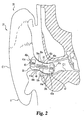
- FIGS. 2-4 further details concerning device 40a as positioned in canal C1 are shown, it being understood that device 40b is similarly configured, but is not depicted in FIG. 2 to enhance clarity.
- FIG. 2 provides a more detailed view of device 40a relative to the structures of ear E1 and body structures in the vicinity of ear E1.
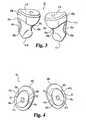
- FIG. 3 presents a perspective view of devices 40a and 40b.
- FIG. 3 further illustrates the curvilinear contours in three dimensions of devices 40a and 40b arranged to generally conform to the approximate S-shape of ear canals CI and C2, respectively.
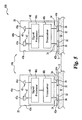
- FIG. 4 presents an end view of housing 41a and 41b, showing end portions 41c and 41d, respectively that are positioned inside ears E1 and E2 when devices 40a and 40b are placed in the respective ear canals C1 and C2. End portions 41c and 41d are each shown with an aperture to facilitate the delivery of a hearing stimulus as is further described hereinafter. Opposite end portions 41 c and 41d are corresponding end portions 41 e and 41f of housings 41 a and 41 b, respectively.
- End portions 41e and 41f are visible at the exterior opening of ear canal CI when device 40a is worn in a normal fashion. End portions 41e and 41f are also each shown with an aperture to facilitate reception of sound as is further described hereinafter.
- Housing 41a includes upper side portion 49a opposite lower side portion 49b, and housing 41 b includes upper side portion 49c opposite lower side portion 49d. Side portions 49a and 49b are positioned between and joining together end portions 41c and 41e, and side portions 49c and 49d are positioned between and joining together end portions 41 d and 41 f.
- Devices 40a and 40b each include a pair of electrodes 32 configured to contact skin S of body B along respective ear canals CI and C2, and/or be placed in close proximity to skin S.
- close proximity between two objects means within two (2) millimeters of one another.
- Electrodes 32 operate to transmit and receive signals through skin S of the body B by utilizing body B positioned between devices 40a and 40b to communicate information-containing electrical signals. For the purposes of such communications, it has been found that the performance of electrodes 32 can, as a pair, be modeled as a near-field electromagnetic signal radiator and receptor of a dipole antenna type, utilizing skin S and/or other tissues of body B as transmission media.
- each pair of electrodes 32 of devices 40a and 40b are also designated as dipole antenna 32a in Fig. 2 .
- electrodes 32 of device 40a are alternatively designated antenna constituent 42a and antenna constituent 44a; and electrodes 32 of device 40b are alternatively designated antenna constituent 42b and antenna constituent 44b.
- Antenna constituent 42a is disposed generally opposite antenna constituent 44a along corresponding opposing side portions 49a and 49b of housing 41 a, and antenna constituent 42b is disposed generally opposite antenna constituent 44b along corresponding opposing side portions 49c and 49d of housing 41 b.
- electrodes 32 include a metallic member 34 and a dielectric layer 36 covering at least a portion of member 34.
- Dielectric layer 36 is selected to capacitively couple the corresponding member 34 with skin S of Body B and to protect member 34 from corrosion or other deterioration due to contact with body B.
- metallic member 34 is in the form of a 3 millimeter by 10 millimeter copper strip having a thickness of about 90 micrometers and dielectric layer 36 is in the form of a 90 micrometer thick, standard hearing aid lacquer.
- a relatively thinner dielectric layer 36 of about 8 micrometers of Galxyl-parylene is utilized.
- member 34 and/or dielectric layer 36 can be utilized for member 34 and/or dielectric layer 36 as would occur to those skilled in the art.
- dielectric layer 36 is absent. It should be understood that the specific shape of electrodes 32 and/or spacing between electrodes may vary with differently sized and/or shaped housings.
- devices 40a and 40b each include sound sensor 45 in the form of microphone 45a.
- Microphone 45a can be of an omnidirectional type, or a directional type such as those with a cardioid, hypercardioid, or figure-8 directional pattern to name just a few.
- Each device 40a, 40b can include more than one sound sensor and/or microphone 45a can be of a type that includes multiple sound-detecting elements.
- Collectively sensors 45 of devices 40a and 40b define sensing array 45b.
- Devices 40a and 40b also each include at least one hearing stimulator 47 in the form of earphone 47a.
- circuitry 48 includes signal processor 48a and transceiver 48b coupled together to bidirectionally communicate signals therebetween.
- Signal processor 48a is coupled to sensor 45 to receive input signals therefrom, and to stimulator 47 to provide output signals thereto.
- Transceiver 48b is coupled to electrodes 32.
- Signal processor 48a may be comprised of one or more components of a digital type, analog type or a combination of these operable to perform desired operations as described hereinafter.
- Signal processor 48a can be of a programmable variety responsive to programming instructions stored in memory of a volatile and/or nonvolatile type, be of a dedicated hardwired logic variety, and/or execute logic defined by both dedicated hardware and program instructions.
- Signal processor can include only a single central processing unit or a number of processing units. For multiple processing unit embodiments, parallel and/or pipeline processing may be utilized.
- signal processor 48a is based on a customized, digital signal processor in the form of a solid-state, integrated circuit device.
- Transceiver refers broadly to any device having a capability to transmit and receive information.
- Transceiver 48b includes a transmitter (not shown) and receiver (not shown) both coupled to electrodes 32 to transmit and receive information-containing electrical signals. These electrical signals are typically transmitted in a modulated format that conveys digital information, including but not limited to one or more of the following: Amplitude Shift Keying (ASK), a Frequency Shift Keying (FSK), Phase Shift Keying (PSK), Pulse Width Modulation (PWM), or Pulse Amplitude Modulation (PAM), Quadrature Amplitude Modulation (QAM), Orthogonal Frequency Division Multiplexing (OFDM), or spread spectrum techniques.
- ASK Amplitude Shift Keying
- FSK Frequency Shift Keying
- PSK Phase Shift Keying
- PWM Pulse Width Modulation
- PAM Pulse Amplitude Modulation
- QAM Quadrature Amplitude Modulation
- an analog signal format and/or modulation technique such as analog Amplitude Modulation (AM) or Frequency Modulation (FM)
- the transmitter includes a drive amplifier to output an electrical signal that generates a desired electric potential level across electrodes 32 while in contact with skin S.
- Components of transceiver 48b are selected to provide a desired level of impedance matching with skin S, including, but not limited to baluns, predefined cable lengths, and/or other passive components, just to name a few.
- Circuitry 48 further includes any power supplies (not shown), filters, signal conditioners, format converters (such as analog-to-digital and/or digital-to- analog converters), volatile memories, nonvolatile memories, and the like desired to perform its operations. Electrical power can be provided in the form of an electrochemical cell or battery and/or a different source as would occur to those skilled in the art.
- Devices 40a and 40b are positioned in ear canals C1 and C2, respectively.
- antenna constituent 42a of device 40a and antenna constituent 42b of device 40b each contact or are in close proximity to upper skin regions 26a and 26b ( FIGS. 1 and 2 ) along a top portion of ear canals CI and C2.
- antenna constituent 44a of device 40a and antenna constituent 44b of device 40b each contact or are in close proximity to lower skin regions 28a and 28b ( FIGS. 1 and 2 ) along a bottom portion of ear canals CI and C2.
- signals from signal processor 48a of the transmitting device 30 are encoded with the corresponding transceiver 48b and output as a time-varying electric potential across electrodes 32 of such device 30.
- the receiving device 30 detects the time- varying electrical signals with its transceiver 48b and decodes such signals for use by its signal processor 48a.
- the preferred range of carrier frequencies for such information-containing electrical signals is in a range of about 3 MegaHertz (MHz) through about 30 GigaHertz (GHz). A more preferred range is about 10 MHz through about 1 GHz.
- This form of electrical signal communication uses skin S and/or other tissues of body B as a transmission line, such that at least two spaced apart electrodes, forming a dipole antenna, contact or are in close proximity to body B at each transmission and reception site.
- other techniques have at most only one contact pathway, relying instead on a pathway through Earth ground or the atmosphere to provide an electrical potential difference necessary to provide a closed loop pathway for electrical signal communication.
- the bidirectional (two-way) communication of signals through body B via pairs of electrodes 32 for each of device 30 is represented by a double-headed arrow.
- one or more of devices 30 can be configured for only one- way communication, being limited to just transmission or reception.
- Consistent coupling of electrodes 32 to skin S is generally desirable because it provides for more consistent transmission characteristics of electrical signals through body B. It has been found that the anterior and posterior sides of the ear canals tend to change shape with nominal movements of the jaw, such as talking and eating, making consistent contact with electrodes 32 of devices 40a and 40b difficult. In contrast, movements of the top and bottom portions of the ear canals with nominal jaw movements are generally much less. Accordingly it has been advantageously discovered that more consistent contact between electrodes 32 and skin S within the ear canal can be achieved by placement of the electrodes 32 in a manner to contact and/or be proximate to skin S along the top and/or bottom portions of the ear canal (such as skin regions 26a, 26b, 28a, and 28b).
- disposing antennae pairs on opposite sides of housing 41 a and 41 b has been found to reduce capacitance between antennae that also provides a more desirable impedance level for communications via human skin.
- one or more electrodes may be located along skin in an anterior or posterior region along the ear canal and/or two or more electrodes (antennae) may not be positioned opposite one another.
- the corresponding sensors 45 are utilized to pick up sound which is converted into an electrical input signal that is provided to circuitry 48.
- the sound signals from the spaced apart sensors 45 can be utilized to selectively enhance sound originating from a particular direction relative to sounds (noise) from other directions utilizing a fixed or adaptive beamforming routine, and/or other binaural signal processing routine for a hearing aid or system as described, for example, in International Patent Applications Nos. PCT/US01/15047 , PCT/US01/14945 , or PCT/US99/26965 ; U. S. Patent Application Nos. 09/805,233 , 09/568,435 , or 09/568,430 ; and/or U.
- At least one of devices 40a and 40b receives sound- representative signals from sensor 45 of the other of devices 40a and 40b to generate an enhanced output signal for one of stimulators 47 to stimulate hearing of the user.
- bidirectional communications between devices 40a and 40b are envisioned as part of the execution of routines of the type referenced hereinbefore. Further, communications between device 40a and 40b can be desired to share processing workload between the corresponding signal processors 48a in a distributed manner and/or to perform diagnostic or troubleshooting routines of one device 30 with another device 30.
- devices 40a and 40b are shown as being of an In-The-Ear (ITE) type, one or more of these devices can be of a Completely-In-The-Ear-Canal (CIC) type or Behind-The-Ear (BTE) type.
- ITE In-The-Ear
- CIC Completely-In-The-Ear-Canal
- BTE Behind-The-Ear
- FIG. 6 illustrates another communication system 120 where like reference numerals refer to like features previously described in connection with system 20.
- System 120 is in the form of hearing system 121.
- System 121 includes three hearing system devices 130.
- Devices 130 are more specifically designated Behind-the-Ear (BTE) devices 140a and 140b, and implant 140c.
- BTE Behind-the-Ear
- devices 140a and 140b each include housing 141 and each include a pair of spaced apart electrodes 132.
- Housing 141 is shaped to fit behind either ear EI and E2 of body B of system user U.
- housing 141 When positioned behind ear E1 or E2, housing 141 is generally located between the corresponding pinna P1 or P2 and cranial region CR1 or CR2 of the user U, respectively.
- Housing 141 is made from an electrical insulator.
- Housing 141 includes a lower portion 141a opposite an upper portion 141b joined together by two opposing sides 141c. At its lowest extreme, portion 141a defines a lower contour 141d.
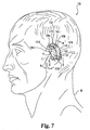
- Lower contour 141d is schematically indicated by a corresponding dashed line of heavier weight in Fig. 7 .
- Lower contour 141d generally defines a hook-shape to facilitate behind-the-ear fitting.
- Lower contour 141d can be curvilinear, rectilinear, or a combination of both. As illustrated in FIG.
- angle A is between about 60 and 120 degrees. More preferably, angle A is between about 75 and 105 degrees. Still more preferable, angle A is approximately 90 degrees. Nonetheless, in other embodiments, a different angle A can be utilized.
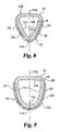
- Electrodes 132 are each comprised of a metallic member 134 and a dielectric layer 136 at least partially covering the metallic member 134 as best shown in FIGS. 8,9 , and 11 .
- the composition of members 134 and/or layer 136 can be as described in connection with member 34 and dielectric layer 36 of electrodes 32.
- each of the upper electrodes 132 are alternatively designated antenna constituent 142
- each of the lower electrodes 132 are alternatively designated antenna constituent 144.
- Antenna constituents 142 and 144 are operable as a dipole antenna in the near field as alternatively designated by reference numeral 132a in Figs. 8 and 9 .
- antenna constituent 142 was provided in the form of a 9 millimeter wide copper strip and antenna constituent 144 was provided in the form of a 15 millimeter wide copper strip both having a thickness of 90 micrometers.
- antenna constituent 142,144 and/or dielectric layer 136 can be utilized as would occur to those skilled in the art.
- Housing 141 is generally symmetric about a plane that intersects contour 141a.
- This plane of symmetry (POS) is perpendicular to the view plane of FIGS. 8-10 , being represented by the axis labeled POS.
- the plane of symmetry is parallel to the view plane of FIG. 7 .
- antenna constituent 142 extends from lower contour 141d (represented by cross-hairs) to either of opposing sides 141c to present a U or V shape that wraps around the plane of symmetry represented by axis POS and, like housing 141, is generally symmetric about this plane.
- axis POS the partial sectional view of FIG.
- antenna constituent 144 extends from lower contour 141d (represented by cross-hairs) to opposing sides 141c to present a U or V shape that wraps around the plane of symmetry represented by axis POS and, like housing 141, is generally symmetric about this plane.
- the symmetry of housing 141, antenna constituent 142 and antenna constituent 144 with respect to the plane represented in FIGS. 8 and 9 facilitates the interchangeability of devices 140a and 140b between right and left ears E1 and E2, respectively.
- antenna constituents 142 and 144 are separated from one another along contour 141d by at least 10 millimeters to reduce capacitance therebetween.
- the separation distance between antenna constituent 142 and 144 along contour 141d of housing 141 is at least 15 millimeters. In a still more preferred embodiment, this separation distance is at least 20 millimeters.
- antenna constituent 142 and 144 are arranged along housing 141 so that antenna constituent 142 contacts or is in close proximity to skin region 126a above an uppermost extreme 129a of concha C of the ear and antenna constituent 144 contacts or is in close proximity to skin region 126b at a level below extreme 129a as illustrated in FIG. 7 .
- antenna constituent 142 contacts or is proximal to skin region 126a at a point above and anterior to skin region 126b as positioned relative to antenna constituent 144.
- Antenna constituent 142 and 144 can contact or be proximal to skin S that joins the pinnae PI, P2 and corresponding cranial regions CR1, CR2; skin S on the pinnae P1, P2; and/or skin on cranial regions CR1, CR2; respectively.
- each device 140a and 140b includes a sound sensor 145 in the form of microphone 145a that can be any of the types previously described. Collectively, sensors 145 of devices 140a and 140b define a sound sensing array 147. Housing 141 defines cavity 146 to contain circuitry 148. Circuitry 148 includes transceiver 148b coupled to corresponding antenna constituents 142 and 144. Transceiver 148b is of the type described in connection with system 20. Circuitry 148 also includes signal processor 148a that can be configured in any of the ways described for signal processor 48a, with its programmed and/or hardwired logic adapted to perform operations described hereinafter for system 120.
- Circuitry 148 further includes any power supplies (not shown), filters, signal conditioners, format converters (such as analog-to- digital and/or digital-to-analog converters), volatile memories, nonvolatile memories, and the like desired to perform its operations. Electrical power can be provided in the form of an electrochemical cell or battery and/or a different source as would occur to those skilled in the art.
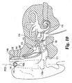
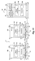
- Implant 140c is illustrated in FIG. 10 relative to various internal structures associated with ear E1 and in an operational schematic form in the diagram of FIG. 11 .
- Implant 140c includes enclosure 161 encapsulating signal processing circuitry 168.
- Enclosure 161 is implanted in the mastoid region of ear E1.
- enclosure 161 is made from titanium, a ceramic material, or such other body-compatible material as would occur to those skilled in the art.
- Signal processing circuitry includes signal processor 168a and transceiver 168b.
- Implant 140c also includes hearing stimulation apparatus 170 coupled to signal processing circuitry 168 via one or more wires or cables from enclosure 161.
- Hearing stimulation apparatus 170 includes middle ear actuator 172 coupled to the middle ear region in the vicinity of the auditory canal.
- Hearing stimulation apparatus 170 also includes an electromechanical intracochlear actuator 174, such as a bone conduction cochlear stimulator coupled to the small bones of the ear (malleus, incus, and/or stapes), and intracochlear stimulation electrodes 176 implanted within the cochlea.
- implant 140c further includes auditory canal microphone 180 coupled to circuitry 168 via cabling. Microphone 180 can be used to detect acoustic signals in addition to or in lieu of sensors 145 to enhance natural sound perception of the user.
- Devices 140a and 140b are arranged to pick up sound with array 147 and bidirectionally communicate using body B as an electrical signal transmission line between corresponding pairs of antenna constituents 142 and 144 in the manner previously described for the devices 40a and 40b of system 20.
- one or more of signal processors 148a of devices 140a and 140b can be configured to generate an output in accordance with a fixed or adaptive beamforming routine and/or other binaural signal processing routine.
- implant 140c receives the output from device 140a and/or 140b to correspondingly stimulate hearing of the user U with one or more of the hearing stimulation apparatus 170 previously described. Bidirectional communication between devices 140a and 140b, and implant 140c is represented by double-headed arrows in FIG. 11 .
- Implant 140c Communication between implant 140c and one or more of devices 140a and 140b can be by a wire or cable connection, through magnetic induction with an induction coil, through electrical signal transmission utilizing electrodes of the type provided for communication between devices 140a and 140b, through ultrasonic communication, and/or through such different means as would occur to those skilled in the art.
- implant 140c is only configured to receive communication signals.
- one or more of devices 140a and 140b can be arranged to only transmit or receive signals via electrodes 32.
- implant 140c is provided in a hearing system with one or more ITE and/or CIC hearing system devices that communicate via electrode pairs.
- microphone 180 is typically absent.
- One or more ITE or CIC hearing system devices in these arrangements can be used in addition to or in place of corresponding BTE hearing system devices.
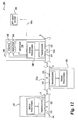
- FIG. 12 schematically illustrates communication system 220 including ear-worn hearing system devices 230 each coupled to skin S of body B by a pair of electrodes 232.
- Devices 230 can be configured the same as ITE devices 40a and 40b, BTE devices 140a and 140b, or a combination of these.
- electrodes 232 are configured the same as electrodes 32 or 132, and each pairing of electrodes 232 for a device is alternatively designated dipole antenna 232a.
- System 220 further includes hearing system control device 240 with a corresponding electrode pair 232.
- Device 240 provides user control over system 220 and an off-body communication interface with off-body device 290.
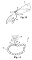
- Device 240 can be provided in different forms, including but not limited to eyeglasses, a headband, a necklace and the like; or in the form of a wrist worn device 241 with a coupling wrist band or strap 241 a as shown in FIG. 13 . Indeed, device 240 can be integrated into a wristwatch or made to appear as one.
- the WATCHPILOT provided by PHONAK AG, which has a business address of Laubisrtistrasse 28,8712 Stafa, Switzerland, could be adapted to such use.
- Device 240 includes user control 242 arranged to provide input through one or more push buttons, rotary dials, switches, or the like.
- Device 240 also includes indicator 243 to provide user- observable output.
- Indicator 243 is typically in the form of a Liquid Crystal Display (LCD) or Light Emitting Diode (LED) display, but can be differently configured as would occur to those skilled in the art.
- Device 240 also includes off-body communication interface 245, which can be of a cable connected variety, wireless variety, or a combination of such varieties. In one wireless Radio Frequency (RF) based form, communication is performed in accordance with a BLUETOOTH or AUTOCOM standard, and/or a MICROLINK or MLX standard from PHONAK AG. In addition or as an alternative, interface 245 can communicate through another wireless technique and/or by cable connection.
- RF Radio Frequency
- Device 240 further includes signal processing/communication circuitry 268 coupled to control 242, indicator 243, and interface 245.
- circuitry 268 includes one or more signal processing units operable to execute programmed and/or hardwired logic to facilitate Input and/or Output (I/O) via control 242, indicator 243, interface 245, and perform any desired data modifications, conversions, storage, or the like; and includes any signal conditioners, filters, format converters (such as analog-to-digital and/or digital- to-analog types), amplifiers, power sources, or the like to implement desired operations as would occur to those skilled in the art.
- Device 240 communicates with devices 230 through a time-varying electrical signal transmitted through body B via electrodes 232 in the manner previously described in connection with systems 20 and 120.
- Interface 245 operatively connects with off-body device 290 via a communication link represented by the doubled headed arrow designated with reference numeral 245c.
- This communication link can be of a temporary or relatively permanent type.
- Off-body device 290 can be arranged as an audio satellite, providing a remote audio input to the user from a Public Address System (PAS), telephonic communication link, one or more remote microphones, an entertainment source such as a radio, television, MP3 player, tape player, CD player, etc. and/or a different type of audio satellite as would occur to those skilled in the art, just to name a few.
- PAS Public Address System
- off-body device 290 can provide data and/or parametric values used in the operation of system 220.
- Interface 245 can also be used in conjunction with device 290 to perform testing of one or more devices 230 and/or of system 220 collectively; communicate system or device diagnosis; and/or system/device performance data.
- FIG. 14 depicts a partial diagrammatic view of communication system 320, where like reference numerals refer to like features.
- System 320 can include one or more of the ear worn devices of systems 20,120, and 220 and/or one or more implants 140c (not shown) that communicate with time-varying electrical signals transmitted through body B.
- System 320 includes an alternative body- worn control device in the form of jewelry that is depicted as bracelet 340 with control device 341.
- Bracelet 340 is shown interfaced with off-body device 290, and includes electrodes 232.
- Control device 341 can incorporate the features of device 240.
- an earring is utilized that clips to an earlobe of the user.
- two or more control devices can be utilized and/or one or more implants may also be included.
- a control device can be used in lieu of one or more ear-worn modules, such as ITE, CIC, or BTE devices.
- a control device is not worn or carried on the body, but instead is temporarily used to provide audio input, perform diagnostic testing, update/modify software, or perform such different operation as would occur to those skilled in the art.
- ear-to-ear communication can be utilized between BTE devices 140a and 140b of system 120 to implement a fixed or adaptive beamformer routine or a different binaural routine.
- at least one of BTE devices 140a and 140b is configured with an earphone to stimulate hearing of user U with adaptation to operate in the manner described for devices 40a and 40b of system 20, and implant 140c being absent.
- System 420 depicted in FIG. 15 provides an example of a BTE device 440 with earphone 447a.
- Fig. 15 illustrates still another communication system 420 where like reference numerals refer to like features previously described.
- System 420 is in the form of hearing system 421 that includes hearing system devices 440 and 460.
- Hearing system device 440 includes member 440a coupled to member 440b by member 440c.
- Member 440a includes a rigid housing member 441a shaped and configured to fit behind the ear E1 of a person's body B. Housing member 441a can be shaped the same as housing 141 of devices 140a and 140b described in connection with system 121.
- Member 440a also includes sensor 145 in the form of microphone 145a as previously described, and a hearing stimulator 447 that can be of the type described in connection with devices 40a and 40b of system 20.
- member 440a houses circuitry 448 that is configured the same as circuitry 48,148, and/or variations thereof to perform fixed beamforming, adaptive beamforming, and/or different binaural routines with adaptation to include logic to operate device 440 according to the manner described hereinafter.
- Circuitry 448 is operatively coupled to sensor 145 and hearing stimulator 447.
- Member 440b is in partial schematic, sectional form in Fig. 15 .
- Member 440b includes housing member 441 b shaped to fit in ear canal CI in the manner described in connection with device 40a of system 20.
- Member 440b defines passageway 450 to transmit sound to ear EI received from member 440c.
- Member 440c includes flexible housing 441c in the form of coupling tube 443 with a passage to transmit this sound from hearing stimulator 447 of member 440a to passageway 450 of member 440b.
- Housing 441c is flexible to permit articulation of members 440a and 440b relative to one another such that member 440b can be readily removed from and inserted in canal CI while member 440a is mounted behind ear EI.
- Device 440 includes a pair of electrodes 432 configured to provide a dipole antenna designated by reference numeral 432a. Electrode 432 carried with member 440a is alternatively designated antenna constituent 442, and electrode 442 carried with member 440b is alternatively designated antenna constituent 444. Further, antenna constituent 444 is shown embedded within member 440b such that portion 446 of member 440b is positioned between skin S 1 along ear canal CI and antenna constituent 444. Portion 446 is comprised of a dielectric material to facilitate capacitive coupling of antenna constituent 444 to body B.
- Electrodes 432 are composed of a metallic material or other suitable electrical conductor. Electrodes 432 are each operatively coupled to circuitry 448. In the case of antenna constituent 444, coupling to circuitry 448 can be accomplished by a cable or wire (not shown) that extends through or is carried with housing member 441 c.
- System 421 can operate in the same manner as system 21 to enhance normal hearing and/or impaired hearing.
- Device 460 can be another device 440; device 40b, 140a, or 140b; or another of the various hearing systems devices previously described, such as a CIC, control device (with or without an off-body interface), and/or implant, to name just a few. Communication between device 440 and 460 can be performed in the same manner as described for previous devices via electrode pairs with each pair operating as a dipole antenna in close proximity to or contact with body B.
- Figs. 16 and 17 illustrate yet another communication system 520.
- System 520 includes hearing system device 540 in the form of a behind-the-ear unit and other hearing system device (s) 560.
- Device 540 includes housing 541 that can be shaped the same as housing 141 of device 140a or 140b previously described.
- Device 540 further includes a number of internal electrodes 532 (four of which are shown). Electrodes 532 are carried within interior 543 of device 540 and are operatively coupled to user control 542. Device 540 also includes user control 542 coupled to electrodes 532. In one form, control 542 is a momentary push- button that can be used to provide an input pulse. Device 540 also includes sensor 145 in the form of microphone 145a as previously described.
- Electrodes 532 are separated from outer surface 541a of housing 541 along lowermost contour 541d by portions 549 of housing 541. Electrodes 532 are positioned to contact interior surface 543a of housing 541, and have more specific individual designations 532a, 532b, 532c, and 532d. In one form, electrodes 532 are plated or otherwise deposited on surface 543a using standard techniques, and are comprised of a metallic material or other suitable electrical conductor. Portions 549 are comprised of a dielectric material configured to capacitively couple electrodes 532 to skin when device 540 is worn behind the ear of a user.
- Circuitry 548 of device 540 that is carried in interior 543 of housing 541.
- Circuitry 548 can be configured the same as previously described circuitry 48,148, and/or variations thereof to perform fixed beamforming, adaptive beamforming, and/or a different binaural routine with the exception of adaptations to include logic to operate device 540 according to the manner described hereinafter.
- Circuitry 548 is operatively coupled to electrodes 532, control 542, and sensor 145. With circuitry 548, any pair of electrodes 532 can be utilized as a dipole antenna to communicate through the body of a user in the manner previously described.
- Fig. 17 also shows a representative cross-section of one of electrodes 532 illustrating its symmetry about axis POS; where axis POS is coextensive with a plane of symmetry for housing 541 and electrodes 532 to facilitate interchange of device 540 between right and left ears.
- circuitry 548 responds to an input from control 542, to successively cause different pairs of electrodes 532 to become active and correspondingly form a dipole antenna. Accordingly, an operator of device 540 can select between different pairings of electrodes 532 to find which electrode pair operates best for communication purposes with one or more of other device (s) 560 ( Fig. 16 ).
- control 542 is a momentary pushbutton type
- Circuitry 548 of device 540 responds to this signal to activate a different one of a number of pairings of electrodes 532.
- a typical initial pair includes electrodes 532 separated from one another by the greatest distance, specifically electrodes 532a and 532d.
- Other pairings selectable with control 542 include: electrodes 532a and 532c; electrodes 532a and 532b; electrodes 532b and 532c; electrodes 532b and 532d; and electrodes 532c and 532d.
- selection can be done with a different type of control and/or can be done in response to programming or another automatic procedure.
- the pairing is selected via an off-body unit.
- the remaining electrodes are not typically utilized to perform communications--being in an inactive state.
- more or fewer electrodes could be utilized than the four illustrated in Fig. 16 .
- different active pairings can be selected among possible pairings of three or more electrodes; where some or all of these electrodes are exterior to the device housing and may or may not otherwise include a dielectric covering.
- electrode pairing selection for devices having three or more electrodes could be utilized with ITC devices, CIC devices, control devices, and the like for other hearing system configurations of the type described herein, or as would otherwise occur to those skilled in the art. Further, it is envisioned that alternative pairings of electrodes for intrabody communication systems and networks other than those used to enhance normal hearing or impaired hearing could be utilized.
- any of the communication techniques and arrangements of the present application could be utilized for systems other than those directed to enhancement of normal or impaired hearing.
- user controlled computing devices such as Personal Digital Assistants (PDAs) could be coupled to an intrabody network with a corresponding electrode pair operating as dipole antennae.
- PDAs Personal Digital Assistants
- medical diagnostic and/or treatment devices could communicate in such a fashion.
- mobile phones, microphones, headphones, virtual reality devices and various other units that may or may not involve hearing and sound reception could utilize dipole antenna communication via electrode pairs of any of types described in connection with the systems 20,120, 220,320, 420, and 520 to participate in a body area network.
Landscapes
- Engineering & Computer Science (AREA)
- Computer Networks & Wireless Communication (AREA)
- Health & Medical Sciences (AREA)
- General Health & Medical Sciences (AREA)
- Neurosurgery (AREA)
- Otolaryngology (AREA)
- Physics & Mathematics (AREA)
- Acoustics & Sound (AREA)
- Signal Processing (AREA)
- Prostheses (AREA)
- Measurement And Recording Of Electrical Phenomena And Electrical Characteristics Of The Living Body (AREA)
- Headphones And Earphones (AREA)
Applications Claiming Priority (2)
| Application Number | Priority Date | Filing Date | Title |
|---|---|---|---|
| US10/340,529 US7512448B2 (en) | 2003-01-10 | 2003-01-10 | Electrode placement for wireless intrabody communication between components of a hearing system |
| EP04701266A EP1584216B1 (de) | 2003-01-10 | 2004-01-09 | Systeme, einrichtungen und verfahren zur drahtlosen intrakörper-kommunikation |
Related Parent Applications (1)
| Application Number | Title | Priority Date | Filing Date |
|---|---|---|---|
| EP04701266.1 Division | 2004-01-09 |
Publications (2)
| Publication Number | Publication Date |
|---|---|
| EP2169982A2 true EP2169982A2 (de) | 2010-03-31 |
| EP2169982A3 EP2169982A3 (de) | 2011-06-01 |
Family
ID=32711350
Family Applications (2)
| Application Number | Title | Priority Date | Filing Date |
|---|---|---|---|
| EP10000002A Withdrawn EP2169982A3 (de) | 2003-01-10 | 2004-01-09 | Systeme, Geräte und Verfahren zur drahtlosen intrakorporellen Kommunikation |
| EP04701266A Expired - Lifetime EP1584216B1 (de) | 2003-01-10 | 2004-01-09 | Systeme, einrichtungen und verfahren zur drahtlosen intrakörper-kommunikation |
Family Applications After (1)
| Application Number | Title | Priority Date | Filing Date |
|---|---|---|---|
| EP04701266A Expired - Lifetime EP1584216B1 (de) | 2003-01-10 | 2004-01-09 | Systeme, einrichtungen und verfahren zur drahtlosen intrakörper-kommunikation |
Country Status (8)
| Country | Link |
|---|---|
| US (1) | US7512448B2 (de) |
| EP (2) | EP2169982A3 (de) |
| JP (1) | JP2006516852A (de) |
| AU (1) | AU2004205043B2 (de) |
| CA (1) | CA2512794C (de) |
| DE (1) | DE602004024956D1 (de) |
| DK (1) | DK1584216T3 (de) |
| WO (1) | WO2004064450A2 (de) |
Cited By (1)
| Publication number | Priority date | Publication date | Assignee | Title |
|---|---|---|---|---|
| US10255422B1 (en) | 2014-09-15 | 2019-04-09 | Apple Inc. | Identity proxy for access control systems |
Families Citing this family (243)
| Publication number | Priority date | Publication date | Assignee | Title |
|---|---|---|---|---|
| US7392091B2 (en) * | 2003-12-30 | 2008-06-24 | Cochlear Limited | Implanted antenna and radio communications link |
| JP4026648B2 (ja) * | 2004-04-19 | 2007-12-26 | ソニー株式会社 | イヤホンアンテナ及びこのイヤホンアンテナを備えた携帯型無線機 |
| JP3933148B2 (ja) * | 2004-06-04 | 2007-06-20 | ソニー株式会社 | イヤホンアンテナ及びこのイヤホンアンテナを備えた携帯型無線機 |
| TWI277355B (en) * | 2004-07-08 | 2007-03-21 | Sony Corp | Earphone antenna connecting device and portable wireless device |
| JP2008511217A (ja) * | 2004-08-27 | 2008-04-10 | ビクトリオン テクノロジー カンパニー リミテッド | 鼻骨伝導式無線通信伝送装置 |
| EP1821432B1 (de) * | 2004-12-08 | 2011-07-06 | Seiko Instruments Inc. | Informationsübertragung über ein menschenkörpersystem und empfänger/sender |
| US7856275B1 (en) * | 2005-01-07 | 2010-12-21 | Ric Investments, Llc | Vestibular system stimulation apparatus |
| US20060236120A1 (en) * | 2005-04-14 | 2006-10-19 | Ibm Corporation | Method and apparatus employing stress detection for highly secure communication |
| US20060236121A1 (en) * | 2005-04-14 | 2006-10-19 | Ibm Corporation | Method and apparatus for highly secure communication |
| US8730031B2 (en) | 2005-04-28 | 2014-05-20 | Proteus Digital Health, Inc. | Communication system using an implantable device |
| US8912908B2 (en) | 2005-04-28 | 2014-12-16 | Proteus Digital Health, Inc. | Communication system with remote activation |
| US8802183B2 (en) | 2005-04-28 | 2014-08-12 | Proteus Digital Health, Inc. | Communication system with enhanced partial power source and method of manufacturing same |
| US9198608B2 (en) | 2005-04-28 | 2015-12-01 | Proteus Digital Health, Inc. | Communication system incorporated in a container |
| US8836513B2 (en) | 2006-04-28 | 2014-09-16 | Proteus Digital Health, Inc. | Communication system incorporated in an ingestible product |
| CA2789262C (en) | 2005-04-28 | 2016-10-04 | Proteus Digital Health, Inc. | Pharma-informatics system |
| US8391990B2 (en) | 2005-05-18 | 2013-03-05 | Cardiac Pacemakers, Inc. | Modular antitachyarrhythmia therapy system |
| US7498478B2 (en) * | 2005-08-31 | 2009-03-03 | Kimberly-Clark Worldwide, Inc. | Method of detecting the presence of an insult in an absorbent article |
| US7355090B2 (en) * | 2005-08-31 | 2008-04-08 | Kimberly-Clark Worldwide, Inc. | Method of detecting the presence of insults in an absorbent article |
| US7649125B2 (en) * | 2005-08-31 | 2010-01-19 | Kimberly-Clark Worldwide, Inc. | Method of detecting the presence of an insult in an absorbent article and device for detecting the same |
| WO2007028035A2 (en) | 2005-09-01 | 2007-03-08 | Proteus Biomedical, Inc. | Implantable zero-wire communications system |
| US7548211B2 (en) * | 2006-03-30 | 2009-06-16 | Phonak Ag | Wireless audio signal receiver device for a hearing instrument |
| US8956287B2 (en) | 2006-05-02 | 2015-02-17 | Proteus Digital Health, Inc. | Patient customized therapeutic regimens |
| US8818517B2 (en) | 2006-05-05 | 2014-08-26 | Advanced Bionics Ag | Information processing and storage in a cochlear stimulation system |
| US7876906B2 (en) | 2006-05-30 | 2011-01-25 | Sonitus Medical, Inc. | Methods and apparatus for processing audio signals |
| US20080049961A1 (en) * | 2006-08-24 | 2008-02-28 | Brindisi Thomas J | Personal audio player |
| US8054140B2 (en) | 2006-10-17 | 2011-11-08 | Proteus Biomedical, Inc. | Low voltage oscillator for medical devices |
| SG175681A1 (en) | 2006-10-25 | 2011-11-28 | Proteus Biomedical Inc | Controlled activation ingestible identifier |
| US8718193B2 (en) | 2006-11-20 | 2014-05-06 | Proteus Digital Health, Inc. | Active signal processing personal health signal receivers |
| US8364274B1 (en) | 2006-12-29 | 2013-01-29 | Advanced Bionics, Llc | Systems and methods for detecting one or more central auditory potentials |
| EP3785599B1 (de) | 2007-02-01 | 2022-08-03 | Otsuka Pharmaceutical Co., Ltd. | Systeme mit einnehmbaren ereignismarkern |
| WO2008101107A1 (en) | 2007-02-14 | 2008-08-21 | Proteus Biomedical, Inc. | In-body power source having high surface area electrode |
| US7706885B2 (en) | 2007-02-23 | 2010-04-27 | Gradient Technologies, Llc | Transcutaneous electrical nerve stimulation and method of using same |
| WO2008112577A1 (en) | 2007-03-09 | 2008-09-18 | Proteus Biomedical, Inc. | In-body device having a multi-directional transmitter |
| EP2063771A1 (de) | 2007-03-09 | 2009-06-03 | Proteus Biomedical, Inc. | Körperintegrierte vorrichtung mit ausfahrbarer antenne |
| US8540632B2 (en) | 2007-05-24 | 2013-09-24 | Proteus Digital Health, Inc. | Low profile antenna for in body device |
| US8934984B2 (en) | 2007-05-31 | 2015-01-13 | Cochlear Limited | Behind-the-ear (BTE) prosthetic device with antenna |
| US8961412B2 (en) | 2007-09-25 | 2015-02-24 | Proteus Digital Health, Inc. | In-body device with virtual dipole signal amplification |
| EP2197536A1 (de) * | 2007-10-09 | 2010-06-23 | Imthera Medical, Inc. | System und verfahren zur neuralen stimulierung |
| US8634773B2 (en) * | 2007-10-12 | 2014-01-21 | Cochlear Limited | Short range communications for body contacting devices |
| US20100290651A1 (en) * | 2007-11-01 | 2010-11-18 | The University Of Melbourne | Pulse stimulation generation method |
| DK2104378T4 (en) * | 2008-02-19 | 2017-08-28 | Starkey Labs Inc | WIRELESS SIGNAL SYSTEM TO IDENTIFY ACOUSTIC ENVIRONMENT FOR HEARING DEVICES |
| EP3235491B1 (de) | 2008-03-05 | 2020-11-04 | Proteus Digital Health, Inc. | Verzehrbare marker und system für multimodale kommunikationsereignisse |
| EP2265331B2 (de) | 2008-03-28 | 2025-03-19 | Cochlear Limited | Antenne für hinter dem ohr zu tragende vorrichtungen |
| WO2009131755A1 (en) * | 2008-04-24 | 2009-10-29 | Sonitus Medical, Inc. | Microphone placement for oral applications |
| US8503930B2 (en) * | 2008-04-25 | 2013-08-06 | Sonitus Medical, Inc. | Signal transmission via body conduction |
| USD598469S1 (en) * | 2008-06-23 | 2009-08-18 | Harris Jr Leon | Combination MP3 player/ear piece |
| EP2313002B1 (de) | 2008-07-08 | 2018-08-29 | Proteus Digital Health, Inc. | Datengrundlage für einnehmbare ereignismarker |
| CN102176862B (zh) | 2008-08-13 | 2014-10-22 | 普罗透斯数字保健公司 | 可摄入电路 |
| US8588448B1 (en) | 2008-09-09 | 2013-11-19 | Energy Telecom, Inc. | Communication eyewear assembly |
| EP2349445A4 (de) | 2008-11-13 | 2012-05-23 | Proteus Biomedical Inc | Einnehmbares therapieaktivatorsystem und verfahren dafür |
| AU2008246284A1 (en) * | 2008-11-19 | 2010-06-10 | Zao, Ritm Okb | Method for electrical influance on a living organism and device thereof |
| CA2746650A1 (en) | 2008-12-11 | 2010-06-17 | Proteus Biomedical, Inc. | Evaluation of gastrointestinal function using portable electroviscerography systems and methods of using the same |
| TWI424832B (zh) | 2008-12-15 | 2014-02-01 | 波提亞斯數位康健公司 | 與身體有關的接收器及其方法 |
| US9439566B2 (en) | 2008-12-15 | 2016-09-13 | Proteus Digital Health, Inc. | Re-wearable wireless device |
| US9659423B2 (en) | 2008-12-15 | 2017-05-23 | Proteus Digital Health, Inc. | Personal authentication apparatus system and method |
| ES2388488T3 (es) | 2008-12-23 | 2012-10-15 | Koninklijke Philips Electronics N.V. | Combinación de comunicación acoplada al cuerpo y comunicación por radiofrecuencia |
| JP2012514799A (ja) | 2009-01-06 | 2012-06-28 | プロテウス バイオメディカル インコーポレイテッド | 摂取に関連するバイオフィードバックおよび個別薬物療法の方法およびシステム |
| SG172847A1 (en) | 2009-01-06 | 2011-08-29 | Proteus Biomedical Inc | Pharmaceutical dosages delivery system |
| EP2392085B1 (de) * | 2009-01-28 | 2021-06-23 | Samsung Electronics Co., Ltd. | Tragbares endgerät und schalldetektor, die beide unter verwendung eines körpernetzwerks kommunizieren, und datensteuerverfahren dafür |
| US8352046B1 (en) | 2009-01-30 | 2013-01-08 | Advanced Bionics, Llc | Sound processing assembly for use in a cochlear implant system |
| AU2010225449A1 (en) | 2009-03-16 | 2011-10-13 | Cochlear Limited | Transcutaneous modulated power link for a medical implant |
| GB2480965B (en) | 2009-03-25 | 2014-10-08 | Proteus Digital Health Inc | Probablistic pharmacokinetic and pharmacodynamic modeling |
| WO2010129288A2 (en) | 2009-04-28 | 2010-11-11 | Proteus Biomedical, Inc. | Highly reliable ingestible event markers and methods for using the same |
| EP2432458A4 (de) | 2009-05-12 | 2014-02-12 | Proteus Digital Health Inc | Einnehmbarer ereignismarker mit verzehrbarem bestandteil |
| EP2467707A4 (de) | 2009-08-21 | 2014-12-17 | Proteus Digital Health Inc | Vorrichtung und verfahren zur messung biologischer parameter |
| US8460746B2 (en) * | 2009-09-09 | 2013-06-11 | Cochlear Limited | Method of forming insulated conductive element having a substantially continuous barrier layer formed via relative motion during deposition |
| US8726492B2 (en) * | 2009-09-09 | 2014-05-20 | Cochlear Limited | Insulated conductive element having a substantially continuous barrier layer formed through multiple coatings |
| US8433082B2 (en) | 2009-10-02 | 2013-04-30 | Sonitus Medical, Inc. | Intraoral appliance for sound transmission via bone conduction |
| TWI517050B (zh) | 2009-11-04 | 2016-01-11 | 普羅托斯數位健康公司 | 供應鏈管理之系統 |
| UA109424C2 (uk) | 2009-12-02 | 2015-08-25 | Фармацевтичний продукт, фармацевтична таблетка з електронним маркером і спосіб виготовлення фармацевтичної таблетки | |
| EP2531099B1 (de) | 2010-02-01 | 2018-12-12 | Proteus Digital Health, Inc. | Datensammelsystem |
| JP5766219B2 (ja) * | 2010-03-10 | 2015-08-19 | エナージー テレコム インコーポレイテッド | 通信用眼鏡 |
| CN102905672B (zh) | 2010-04-07 | 2016-08-17 | 普罗秋斯数字健康公司 | 微型可吞服装置 |
| TWI557672B (zh) | 2010-05-19 | 2016-11-11 | 波提亞斯數位康健公司 | 用於從製造商跟蹤藥物直到患者之電腦系統及電腦實施之方法、用於確認將藥物給予患者的設備及方法、患者介面裝置 |
| WO2010133702A2 (en) | 2010-09-15 | 2010-11-25 | Advanced Bionics Ag | Partially implantable hearing instrument |
| EP2725655B1 (de) | 2010-10-12 | 2021-07-07 | GN Hearing A/S | Hinter dem Ohr zu tragendes Hörhilfegerät mit einer verbesserten Antenna |
| US9867990B2 (en) | 2010-10-29 | 2018-01-16 | Medtronic, Inc. | Determination of dipole for tissue conductance communication |
| EP2642983A4 (de) | 2010-11-22 | 2014-03-12 | Proteus Digital Health Inc | Einnehmbare vorrichtung mit einem pharmazeutischen produkt |
| EP2461606B1 (de) * | 2010-12-06 | 2017-11-22 | Nxp B.V. | Zeitmultiplexiertes Zugriffsverfahren für den Betrieb eines Nahfeldkommunikationssystems und Nahfeldkommunikationssystem damit |
| WO2012103433A1 (en) | 2011-01-28 | 2012-08-02 | Medtronic, Inc. | Communication dipole for implantable medical device |
| US12115374B2 (en) | 2011-01-28 | 2024-10-15 | Curonix Llc | Microwave field stimulator |
| EP4424360A3 (de) | 2011-01-28 | 2025-01-22 | Curonix LLC | Nervenstimulatorsystem |
| US8412352B2 (en) | 2011-01-28 | 2013-04-02 | Medtronic, Inc. | Communication dipole for implantable medical device |
| US8639335B2 (en) | 2011-01-28 | 2014-01-28 | Medtronic, Inc. | Disabling an implanted medical device with another medical device |
| JP2014514032A (ja) | 2011-03-11 | 2014-06-19 | プロテウス デジタル ヘルス, インコーポレイテッド | 様々な物理的構成を備えた着用式個人身体関連装置 |
| US9220897B2 (en) | 2011-04-04 | 2015-12-29 | Micron Devices Llc | Implantable lead |
| MX346885B (es) | 2011-04-04 | 2017-04-04 | Stimwave Tech Inc | Conductor implantable. |
| US8954177B2 (en) | 2011-06-01 | 2015-02-10 | Apple Inc. | Controlling operation of a media device based upon whether a presentation device is currently being worn by a user |
| US11083391B2 (en) * | 2011-06-10 | 2021-08-10 | Cochlear Limited | Electrode impedance spectroscopy |
| WO2015112603A1 (en) | 2014-01-21 | 2015-07-30 | Proteus Digital Health, Inc. | Masticable ingestible product and communication system therefor |
| US9756874B2 (en) | 2011-07-11 | 2017-09-12 | Proteus Digital Health, Inc. | Masticable ingestible product and communication system therefor |
| KR101898964B1 (ko) | 2011-07-21 | 2018-09-14 | 프로테우스 디지털 헬스, 인코포레이티드 | 모바일 통신 장치, 시스템, 및 방법 |
| US20130030321A1 (en) * | 2011-07-29 | 2013-01-31 | Ming Zhang | Concha electrode |
| CN104080509B (zh) | 2011-07-29 | 2017-09-08 | 米克伦设备有限责任公司 | 用于神经刺激器的功率或极性选择的远程控制 |
| EP2741810B1 (de) | 2011-08-12 | 2021-03-31 | Stimwave Technologies Incorporated | Mikrowellenfeldstimulator |
| JP5802334B2 (ja) | 2011-08-24 | 2015-10-28 | ヴェーデクス・アクティーセルスカプ | 容量性電極を備えるeegモニタおよび脳波モニタリング方法 |
| EP3403690B1 (de) | 2011-09-15 | 2020-08-05 | Stimwave Technologies Incorporated | Relaismodul für ein implantat |
| US9235683B2 (en) | 2011-11-09 | 2016-01-12 | Proteus Digital Health, Inc. | Apparatus, system, and method for managing adherence to a regimen |
| JP5841267B2 (ja) * | 2012-02-13 | 2016-01-13 | ジアンス ベターライフ メディカル カンパニー リミテッドJiangsu Betterlife Medical Co., Ltd | デジタル補聴器 |
| US9319807B2 (en) * | 2012-02-28 | 2016-04-19 | Cochlear Limited | Device with combined antenna and transducer |
| WO2013177006A2 (en) * | 2012-05-21 | 2013-11-28 | Stimwave Technologies, Incorporated | Methods and devices for modulating excitable tissue of the exiting spinal nerves |
| EP2667638B1 (de) | 2012-05-24 | 2016-02-03 | Oticon A/s | Hörgerät mit externer Elektrode |
| US9648409B2 (en) * | 2012-07-12 | 2017-05-09 | Apple Inc. | Earphones with ear presence sensors |
| US20140023216A1 (en) * | 2012-07-17 | 2014-01-23 | Starkey Laboratories, Inc. | Hearing assistance device with wireless communication for on- and off- body accessories |
| CN104487347B (zh) | 2012-07-23 | 2017-09-01 | 普罗秋斯数字健康公司 | 用于制造包括电子器件的片剂的方法和系统 |
| US9351648B2 (en) | 2012-08-24 | 2016-05-31 | Medtronic, Inc. | Implantable medical device electrode assembly |
| CA2888871C (en) | 2012-10-18 | 2016-08-09 | Proteus Digital Health, Inc. | Apparatus, system, and method to adaptively optimize power dissipation and broadcast power in a power source for a communication device |
| CN105264924B (zh) | 2012-11-12 | 2019-04-02 | 埃姆皮公司 | 用于电刺激的无线配对和通信的系统及方法 |
| US9049508B2 (en) | 2012-11-29 | 2015-06-02 | Apple Inc. | Earphones with cable orientation sensors |
| US20140146982A1 (en) | 2012-11-29 | 2014-05-29 | Apple Inc. | Electronic Devices and Accessories with Media Streaming Control Features |
| US9344792B2 (en) | 2012-11-29 | 2016-05-17 | Apple Inc. | Ear presence detection in noise cancelling earphones |
| US8744113B1 (en) | 2012-12-13 | 2014-06-03 | Energy Telecom, Inc. | Communication eyewear assembly with zone of safety capability |
| WO2014105973A1 (en) | 2012-12-26 | 2014-07-03 | Micron Devices, LLC | Wearable antenna assembly |
| WO2014120669A1 (en) | 2013-01-29 | 2014-08-07 | Proteus Digital Health, Inc. | Highly-swellable polymeric films and compositions comprising the same |
| US10175376B2 (en) | 2013-03-15 | 2019-01-08 | Proteus Digital Health, Inc. | Metal detector apparatus, system, and method |
| JP6498177B2 (ja) | 2013-03-15 | 2019-04-10 | プロテウス デジタル ヘルス, インコーポレイテッド | 本人認証装置システムおよび方法 |
| JP6511439B2 (ja) | 2013-06-04 | 2019-05-15 | プロテウス デジタル ヘルス, インコーポレイテッド | データ収集および転帰の査定のためのシステム、装置、および方法 |
| US9532147B2 (en) | 2013-07-19 | 2016-12-27 | Starkey Laboratories, Inc. | System for detection of special environments for hearing assistance devices |
| US9796576B2 (en) | 2013-08-30 | 2017-10-24 | Proteus Digital Health, Inc. | Container with electronically controlled interlock |
| RU2736776C2 (ru) | 2013-09-20 | 2020-11-20 | Протеус Диджитал Хелс, Инк. | Способы, устройства и системы приема и декодирования сигналов в присутствии шума с использованием срезов и деформирования |
| JP2016537924A (ja) | 2013-09-24 | 2016-12-01 | プロテウス デジタル ヘルス, インコーポレイテッド | 事前に正確に把握されていない周波数において受信された電磁信号に関する使用のための方法および装置 |
| US10084880B2 (en) | 2013-11-04 | 2018-09-25 | Proteus Digital Health, Inc. | Social media networking based on physiologic information |
| US9883295B2 (en) | 2013-11-11 | 2018-01-30 | Gn Hearing A/S | Hearing aid with an antenna |
| US9686621B2 (en) | 2013-11-11 | 2017-06-20 | Gn Hearing A/S | Hearing aid with an antenna |
| US9888328B2 (en) * | 2013-12-02 | 2018-02-06 | Arizona Board Of Regents On Behalf Of Arizona State University | Hearing assistive device |
| AU2015204701B2 (en) | 2014-01-10 | 2018-03-15 | Cardiac Pacemakers, Inc. | Systems and methods for detecting cardiac arrhythmias |
| US20150196769A1 (en) | 2014-01-10 | 2015-07-16 | Cardiac Pacemakers, Inc. | Methods and systems for improved communication between medical devices |
| CN106256090B (zh) * | 2014-05-05 | 2020-10-13 | 恩智浦有限公司 | 电磁感应无线通信系统、方法及存储介质 |
| US9819395B2 (en) * | 2014-05-05 | 2017-11-14 | Nxp B.V. | Apparatus and method for wireless body communication |
| US9819075B2 (en) * | 2014-05-05 | 2017-11-14 | Nxp B.V. | Body communication antenna |
| US10014578B2 (en) * | 2014-05-05 | 2018-07-03 | Nxp B.V. | Body antenna system |
| US10015604B2 (en) * | 2014-05-05 | 2018-07-03 | Nxp B.V. | Electromagnetic induction field communication |
| US9812788B2 (en) | 2014-11-24 | 2017-11-07 | Nxp B.V. | Electromagnetic field induction for inter-body and transverse body communication |
| US10009069B2 (en) * | 2014-05-05 | 2018-06-26 | Nxp B.V. | Wireless power delivery and data link |
| CN110665114B (zh) | 2014-05-12 | 2022-12-06 | 斯蒂维科技公司 | 具有小尺寸发射天线的远程rf功率系统 |
| US9808631B2 (en) | 2014-08-06 | 2017-11-07 | Cardiac Pacemakers, Inc. | Communication between a plurality of medical devices using time delays between communication pulses to distinguish between symbols |
| US9757570B2 (en) | 2014-08-06 | 2017-09-12 | Cardiac Pacemakers, Inc. | Communications in a medical device system |
| US9694189B2 (en) | 2014-08-06 | 2017-07-04 | Cardiac Pacemakers, Inc. | Method and apparatus for communicating between medical devices |
| US10595138B2 (en) | 2014-08-15 | 2020-03-17 | Gn Hearing A/S | Hearing aid with an antenna |
| EP3180927B1 (de) | 2014-08-15 | 2020-01-29 | Ihear Medical, Inc. | Kanalhörgerät und verfahren zur drahtlosen fernsteuerung einer vorrichtung |
| US9769577B2 (en) | 2014-08-22 | 2017-09-19 | iHear Medical, Inc. | Hearing device and methods for wireless remote control of an appliance |
| US9526909B2 (en) | 2014-08-28 | 2016-12-27 | Cardiac Pacemakers, Inc. | Medical device with triggered blanking period |
| EP3978068B1 (de) | 2014-09-02 | 2024-10-16 | Cochlear Limited | Einsetzen einer anordnung zur intracochlearen stimulierung |
| US10097933B2 (en) | 2014-10-06 | 2018-10-09 | iHear Medical, Inc. | Subscription-controlled charging of a hearing device |
| US20160134742A1 (en) | 2014-11-11 | 2016-05-12 | iHear Medical, Inc. | Subscription-based wireless service for a canal hearing device |
| US10396948B2 (en) | 2015-01-07 | 2019-08-27 | Northeastern University | Ultrasonic multiplexing network for implantable medical devices |
| ES2713231T3 (es) | 2015-02-06 | 2019-05-20 | Cardiac Pacemakers Inc | Sistemas para el suministro seguro de una terapia de estimulación eléctrica |
| EP3827877B1 (de) | 2015-02-06 | 2024-06-19 | Cardiac Pacemakers, Inc. | Systeme zur behandlung von herzrhythmusstörungen |
| WO2016130477A2 (en) | 2015-02-09 | 2016-08-18 | Cardiac Pacemakers, Inc. | Implantable medical device with radiopaque id tag |
| KR102587532B1 (ko) | 2015-02-27 | 2023-10-11 | 킴벌리-클라크 월드와이드, 인크. | 흡수 용품 누설 평가 시스템 |
| EP3265172B1 (de) | 2015-03-04 | 2018-12-19 | Cardiac Pacemakers, Inc. | System zur behandlung von herzrhythmusstörungen |
| US10050700B2 (en) | 2015-03-18 | 2018-08-14 | Cardiac Pacemakers, Inc. | Communications in a medical device system with temporal optimization |
| CN107427222B (zh) | 2015-03-18 | 2021-02-09 | 心脏起搏器股份公司 | 使用链路质量评估的医疗设备系统中的通信 |
| US10052492B2 (en) * | 2015-05-06 | 2018-08-21 | Verily Life Sciences Llc | Replaceable battery for implantable devices |
| US11051543B2 (en) | 2015-07-21 | 2021-07-06 | Otsuka Pharmaceutical Co. Ltd. | Alginate on adhesive bilayer laminate film |
| WO2017031347A1 (en) | 2015-08-20 | 2017-02-23 | Cardiac Pacemakers, Inc. | Systems and methods for communication between medical devices |
| US9853743B2 (en) | 2015-08-20 | 2017-12-26 | Cardiac Pacemakers, Inc. | Systems and methods for communication between medical devices |
| US9819097B2 (en) | 2015-08-26 | 2017-11-14 | Nxp B.V. | Antenna system |
| US9968787B2 (en) | 2015-08-27 | 2018-05-15 | Cardiac Pacemakers, Inc. | Spatial configuration of a motion sensor in an implantable medical device |
| US9956414B2 (en) | 2015-08-27 | 2018-05-01 | Cardiac Pacemakers, Inc. | Temporal configuration of a motion sensor in an implantable medical device |
| US10137305B2 (en) | 2015-08-28 | 2018-11-27 | Cardiac Pacemakers, Inc. | Systems and methods for behaviorally responsive signal detection and therapy delivery |
| US10226631B2 (en) | 2015-08-28 | 2019-03-12 | Cardiac Pacemakers, Inc. | Systems and methods for infarct detection |
| WO2017040115A1 (en) | 2015-08-28 | 2017-03-09 | Cardiac Pacemakers, Inc. | System for detecting tamponade |
| WO2017044389A1 (en) | 2015-09-11 | 2017-03-16 | Cardiac Pacemakers, Inc. | Arrhythmia detection and confirmation |
| US10065041B2 (en) | 2015-10-08 | 2018-09-04 | Cardiac Pacemakers, Inc. | Devices and methods for adjusting pacing rates in an implantable medical device |
| DK3664473T3 (da) * | 2015-12-14 | 2021-08-16 | Gn Hearing As | Høreapparat |
| JP6608063B2 (ja) | 2015-12-17 | 2019-11-20 | カーディアック ペースメイカーズ, インコーポレイテッド | 植込み型医療装置 |
| US10905886B2 (en) | 2015-12-28 | 2021-02-02 | Cardiac Pacemakers, Inc. | Implantable medical device for deployment across the atrioventricular septum |
| WO2017127548A1 (en) | 2016-01-19 | 2017-07-27 | Cardiac Pacemakers, Inc. | Devices for wirelessly recharging a rechargeable battery of an implantable medical device |
| WO2017136548A1 (en) | 2016-02-04 | 2017-08-10 | Cardiac Pacemakers, Inc. | Delivery system with force sensor for leadless cardiac device |
| US11116988B2 (en) | 2016-03-31 | 2021-09-14 | Cardiac Pacemakers, Inc. | Implantable medical device with rechargeable battery |
| US10320086B2 (en) | 2016-05-04 | 2019-06-11 | Nxp B.V. | Near-field electromagnetic induction (NFEMI) antenna |
| US10668294B2 (en) | 2016-05-10 | 2020-06-02 | Cardiac Pacemakers, Inc. | Leadless cardiac pacemaker configured for over the wire delivery |
| US10328272B2 (en) | 2016-05-10 | 2019-06-25 | Cardiac Pacemakers, Inc. | Retrievability for implantable medical devices |
| JP6764956B2 (ja) | 2016-06-27 | 2020-10-07 | カーディアック ペースメイカーズ, インコーポレイテッド | 再同期ペーシング管理に皮下で感知されたp波を使用する心臓治療法システム |
| US11207527B2 (en) | 2016-07-06 | 2021-12-28 | Cardiac Pacemakers, Inc. | Method and system for determining an atrial contraction timing fiducial in a leadless cardiac pacemaker system |
| WO2018009392A1 (en) | 2016-07-07 | 2018-01-11 | Cardiac Pacemakers, Inc. | Leadless pacemaker using pressure measurements for pacing capture verification |
| CN109475743B (zh) | 2016-07-20 | 2022-09-02 | 心脏起搏器股份公司 | 在无引线心脏起搏器系统中利用心房收缩定时基准的系统 |
| CN109843149B (zh) | 2016-07-22 | 2020-07-07 | 普罗秋斯数字健康公司 | 可摄入事件标记的电磁感测和检测 |
| WO2018035343A1 (en) | 2016-08-19 | 2018-02-22 | Cardiac Pacemakers, Inc. | Trans septal implantable medical device |
| EP3503970B1 (de) | 2016-08-24 | 2023-01-04 | Cardiac Pacemakers, Inc. | Kardiale resynchronisierung mittels fusionsförderung zur taktungsverwaltung |
| CN109640809B (zh) | 2016-08-24 | 2021-08-17 | 心脏起搏器股份公司 | 使用p波到起搏定时的集成式多装置心脏再同步治疗 |
| WO2018057626A1 (en) | 2016-09-21 | 2018-03-29 | Cardiac Pacemakers, Inc. | Implantable cardiac monitor |
| WO2018057318A1 (en) | 2016-09-21 | 2018-03-29 | Cardiac Pacemakers, Inc. | Leadless stimulation device with a housing that houses internal components of the leadless stimulation device and functions as the battery case and a terminal of an internal battery |
| US10758737B2 (en) | 2016-09-21 | 2020-09-01 | Cardiac Pacemakers, Inc. | Using sensor data from an intracardially implanted medical device to influence operation of an extracardially implantable cardioverter |
| US10820831B2 (en) | 2016-10-26 | 2020-11-03 | Proteus Digital Health, Inc. | Methods for manufacturing capsules with ingestible event markers |
| US10413733B2 (en) | 2016-10-27 | 2019-09-17 | Cardiac Pacemakers, Inc. | Implantable medical device with gyroscope |
| WO2018081275A1 (en) | 2016-10-27 | 2018-05-03 | Cardiac Pacemakers, Inc. | Multi-device cardiac resynchronization therapy with timing enhancements |
| AU2017350759B2 (en) | 2016-10-27 | 2019-10-17 | Cardiac Pacemakers, Inc. | Implantable medical device with pressure sensor |
| WO2018081237A1 (en) | 2016-10-27 | 2018-05-03 | Cardiac Pacemakers, Inc. | Use of a separate device in managing the pace pulse energy of a cardiac pacemaker |
| US10758724B2 (en) | 2016-10-27 | 2020-09-01 | Cardiac Pacemakers, Inc. | Implantable medical device delivery system with integrated sensor |
| WO2018081133A1 (en) | 2016-10-27 | 2018-05-03 | Cardiac Pacemakers, Inc. | Implantable medical device having a sense channel with performance adjustment |
| EP3532157B1 (de) | 2016-10-31 | 2020-08-26 | Cardiac Pacemakers, Inc. | Systeme zur aktivitätsgradstimulation |
| US10434317B2 (en) | 2016-10-31 | 2019-10-08 | Cardiac Pacemakers, Inc. | Systems and methods for activity level pacing |
| WO2018089311A1 (en) | 2016-11-08 | 2018-05-17 | Cardiac Pacemakers, Inc | Implantable medical device for atrial deployment |
| WO2018089308A1 (en) | 2016-11-09 | 2018-05-17 | Cardiac Pacemakers, Inc. | Systems, devices, and methods for setting cardiac pacing pulse parameters for a cardiac pacing device |
| EP3541473B1 (de) | 2016-11-21 | 2020-11-11 | Cardiac Pacemakers, Inc. | Elektrodenloser herzschrittmacher mit multimodaler kommunikation |
| US10639486B2 (en) | 2016-11-21 | 2020-05-05 | Cardiac Pacemakers, Inc. | Implantable medical device with recharge coil |
| EP3541472B1 (de) | 2016-11-21 | 2023-06-07 | Cardiac Pacemakers, Inc. | Implantierbare medizinische vorrichtung mit einem magnetisch permeablen gehäuse und einer um das gehäuse herum angeordneten induktiven spule |
| US10881869B2 (en) | 2016-11-21 | 2021-01-05 | Cardiac Pacemakers, Inc. | Wireless re-charge of an implantable medical device |
| CN109982746B (zh) | 2016-11-21 | 2023-04-04 | 心脏起搏器股份公司 | 提供心脏再同步治疗的无引线心脏起搏器 |
| EP3343952A1 (de) | 2016-12-30 | 2018-07-04 | GN Hearing A/S | Modulares hörgerät mit elektroakustischen kalibrierungsparametern |
| US11207532B2 (en) | 2017-01-04 | 2021-12-28 | Cardiac Pacemakers, Inc. | Dynamic sensing updates using postural input in a multiple device cardiac rhythm management system |
| CN110198759B (zh) | 2017-01-26 | 2023-08-11 | 心脏起搏器股份公司 | 具有可拆卸固定件的无引线可植入装置 |
| JP7000438B2 (ja) | 2017-01-26 | 2022-01-19 | カーディアック ペースメイカーズ, インコーポレイテッド | 冗長メッセージ送信を伴う人体デバイス通信 |
| CN110234392B (zh) | 2017-01-26 | 2023-08-11 | 心脏起搏器股份公司 | 具有被包覆模制的组件的无引线装置 |
| US10821288B2 (en) | 2017-04-03 | 2020-11-03 | Cardiac Pacemakers, Inc. | Cardiac pacemaker with pacing pulse energy adjustment based on sensed heart rate |
| US10905872B2 (en) | 2017-04-03 | 2021-02-02 | Cardiac Pacemakers, Inc. | Implantable medical device with a movable electrode biased toward an extended position |
| KR102099784B1 (ko) | 2017-04-05 | 2020-04-10 | 킴벌리-클라크 월드와이드, 인크. | 흡수 용품 누출 검출 의복 및 이를 이용한 흡수 용품 누출 검출 방법 |
| WO2019036568A1 (en) | 2017-08-18 | 2019-02-21 | Cardiac Pacemakers, Inc. | IMPLANTABLE MEDICAL DEVICE COMPRISING A FLOW CONCENTRATOR AND A RECEPTION COIL PROVIDED AROUND THE FLOW CONCENTRATOR |
| EP3668592B1 (de) | 2017-08-18 | 2021-11-17 | Cardiac Pacemakers, Inc. | Implantierbare medizinische vorrichtung mit drucksensor |
| JP6938778B2 (ja) | 2017-09-20 | 2021-09-22 | カーディアック ペースメイカーズ, インコーポレイテッド | 複数の作動モードを備えた移植式医療用装置 |
| US11185703B2 (en) | 2017-11-07 | 2021-11-30 | Cardiac Pacemakers, Inc. | Leadless cardiac pacemaker for bundle of his pacing |
| EP3717059B1 (de) | 2017-12-01 | 2024-11-20 | Cardiac Pacemakers, Inc. | Systeme zur erkennung von referenzpunkten für die vorhofkontraktionszeit innerhalb eines suchfensters von einem ventrikulär implantierten leitungslosen herzschrittmacher |
| EP3717063B1 (de) | 2017-12-01 | 2023-12-27 | Cardiac Pacemakers, Inc. | Systeme zum erkennen von vorhofkontraktions-timing-bezugswerte und zum bestimmen eines herzintervalls von einem ventrikulär implantierten leitungslosen herzschrittmacher |
| WO2019108545A1 (en) | 2017-12-01 | 2019-06-06 | Cardiac Pacemakers, Inc. | Methods and systems for detecting atrial contraction timing fiducials during ventricular filling from a ventricularly implanted leadless cardiac pacemaker |
| EP3717060B1 (de) | 2017-12-01 | 2022-10-05 | Cardiac Pacemakers, Inc. | Leitungsloser herzschritzmascher mit reversionärem verhalten |
| EP3506655B1 (de) * | 2017-12-29 | 2024-08-14 | GN Hearing A/S | Hörinstrument mit magnetischer induktionsantenne |
| US11529523B2 (en) | 2018-01-04 | 2022-12-20 | Cardiac Pacemakers, Inc. | Handheld bridge device for providing a communication bridge between an implanted medical device and a smartphone |
| EP3735293B1 (de) | 2018-01-04 | 2022-03-09 | Cardiac Pacemakers, Inc. | Zweikammer-stimulation ohne schlag-zu-schlag-kommunikation |
| WO2019152870A1 (en) | 2018-02-01 | 2019-08-08 | Perryman Laura Tyler | Systems and methods to sense stimulation electrode tissue impedance |
| US11058880B2 (en) | 2018-03-23 | 2021-07-13 | Medtronic, Inc. | VFA cardiac therapy for tachycardia |
| JP2021518192A (ja) | 2018-03-23 | 2021-08-02 | メドトロニック,インコーポレイテッド | VfA心臓再同期治療 |
| EP3768369A1 (de) | 2018-03-23 | 2021-01-27 | Medtronic, Inc. | Av-synchrone vfa-herztherapie |
| EP3856331A1 (de) | 2018-09-26 | 2021-08-04 | Medtronic, Inc. | Erfassung in der ventrikel-aus-atrium-herztherapie |
| US11951313B2 (en) | 2018-11-17 | 2024-04-09 | Medtronic, Inc. | VFA delivery systems and methods |
| EP3897816B1 (de) | 2018-12-21 | 2024-03-27 | Medtronic, Inc. | Freisetzungssysteme für linksventrikuläre stimulation |
| CN109891761A (zh) * | 2019-01-31 | 2019-06-14 | 深圳市汇顶科技股份有限公司 | 传输信息的方法、通信装置、便携式设备和通信系统 |
| US11679265B2 (en) | 2019-02-14 | 2023-06-20 | Medtronic, Inc. | Lead-in-lead systems and methods for cardiac therapy |
| US11697025B2 (en) | 2019-03-29 | 2023-07-11 | Medtronic, Inc. | Cardiac conduction system capture |
| US11213676B2 (en) | 2019-04-01 | 2022-01-04 | Medtronic, Inc. | Delivery systems for VfA cardiac therapy |
| US11712188B2 (en) | 2019-05-07 | 2023-08-01 | Medtronic, Inc. | Posterior left bundle branch engagement |
| US11305127B2 (en) | 2019-08-26 | 2022-04-19 | Medtronic Inc. | VfA delivery and implant region detection |
| US11064305B2 (en) * | 2019-09-30 | 2021-07-13 | Sonova Ag | Systems and methods for using a selectively configurable interface assembly to program a hearing device |
| US11813466B2 (en) | 2020-01-27 | 2023-11-14 | Medtronic, Inc. | Atrioventricular nodal stimulation |
| US12543992B2 (en) | 2020-03-30 | 2026-02-10 | Medtronic, Inc. | Pacing efficacy determination using a representative morphology of external cardiac signals |
| US11911168B2 (en) | 2020-04-03 | 2024-02-27 | Medtronic, Inc. | Cardiac conduction system therapy benefit determination |
| US12605103B2 (en) | 2020-05-21 | 2026-04-21 | Medtronic, Inc. | QRS detection and bracketing |
| DE102020209124A1 (de) | 2020-07-21 | 2022-01-27 | Sivantos Pte. Ltd. | ITE-Hörgerät |
| US11813464B2 (en) | 2020-07-31 | 2023-11-14 | Medtronic, Inc. | Cardiac conduction system evaluation |
| US12465770B2 (en) | 2020-07-31 | 2025-11-11 | Medtronic, Inc. | Coronary sinus conduction system pacing and delivery |
| US11422392B2 (en) * | 2020-10-05 | 2022-08-23 | Meta Platforms Technologies, Llc | Ultraminiature dynamic speaker for a fully in-ear monitor |
| CN118266232A (zh) * | 2022-10-28 | 2024-06-28 | 深圳市韶音科技有限公司 | 一种耳机 |
Citations (2)
| Publication number | Priority date | Publication date | Assignee | Title |
|---|---|---|---|---|
| US6222927B1 (en) | 1996-06-19 | 2001-04-24 | The University Of Illinois | Binaural signal processing system and method |
| US9926965B2 (en) | 2012-08-27 | 2018-03-27 | United Technologies Corporation | Pitch diameter shank bolt with shear sleeve |
Family Cites Families (133)
| Publication number | Priority date | Publication date | Assignee | Title |
|---|---|---|---|---|
| NL212819A (de) * | 1955-12-13 | 1900-01-01 | Zenith Radio Corp | |
| US4025721A (en) | 1976-05-04 | 1977-05-24 | Biocommunications Research Corporation | Method of and means for adaptively filtering near-stationary noise from speech |
| FR2383657A1 (fr) | 1977-03-16 | 1978-10-13 | Bertin & Cie | Equipement pour prothese auditive |
| DE2823798C2 (de) | 1978-05-31 | 1980-07-03 | Siemens Ag, 1000 Berlin Und 8000 Muenchen | Verfahren zur elektrischen Stimulation des Hörnervs und Multikanal-Hörprothese zur Durchführung des Verfahrens |
| CA1105565A (en) | 1978-09-12 | 1981-07-21 | Kaufman (John G.) Hospital Products Ltd. | Electrosurgical electrode |
| US4334740A (en) | 1978-09-12 | 1982-06-15 | Polaroid Corporation | Receiving system having pre-selected directional response |
| US4354064A (en) | 1980-02-19 | 1982-10-12 | Scott Instruments Company | Vibratory aid for presbycusis |
| DE3322108A1 (de) | 1982-03-10 | 1984-12-20 | Siemens AG, 1000 Berlin und 8000 München | Sprechanbahnungsgeraet |
| JPS5939198A (ja) | 1982-08-27 | 1984-03-03 | Victor Co Of Japan Ltd | マイクロホン装置 |
| US4536887A (en) | 1982-10-18 | 1985-08-20 | Nippon Telegraph & Telephone Public Corporation | Microphone-array apparatus and method for extracting desired signal |
| US4858612A (en) | 1983-12-19 | 1989-08-22 | Stocklin Philip L | Hearing device |
| DE3420244A1 (de) | 1984-05-30 | 1985-12-05 | Hortmann GmbH, 7449 Neckartenzlingen | Mehrfrequenz-uebertragungssystem fuer implantierte hoerprothesen |
| AT379929B (de) | 1984-07-18 | 1986-03-10 | Viennatone Gmbh | Hoergeraet |
| DE3431584A1 (de) | 1984-08-28 | 1986-03-13 | Siemens AG, 1000 Berlin und 8000 München | Hoerhilfegeraet |
| US4742548A (en) | 1984-12-20 | 1988-05-03 | American Telephone And Telegraph Company | Unidirectional second order gradient microphone |
| JPS6223300A (ja) | 1985-07-23 | 1987-01-31 | Victor Co Of Japan Ltd | 指向性マイクロホン装置 |
| CA1236607A (en) | 1985-09-23 | 1988-05-10 | Northern Telecom Limited | Microphone arrangement |
| DE8529458U1 (de) | 1985-10-16 | 1987-05-07 | Siemens AG, 1000 Berlin und 8000 München | Hörgerät |
| US4988981B1 (en) | 1987-03-17 | 1999-05-18 | Vpl Newco Inc | Computer data entry and manipulation apparatus and method |
| EP0298323A1 (de) | 1987-07-07 | 1989-01-11 | Siemens Aktiengesellschaft | Hörhilfegerät |
| DE8816422U1 (de) | 1988-05-06 | 1989-08-10 | Siemens AG, 1000 Berlin und 8000 München | Hörhilfegerät mit drahtloser Fernsteuerung |
| US5000194A (en) * | 1988-08-25 | 1991-03-19 | Cochlear Corporation | Array of bipolar electrodes |
| DE3831809A1 (de) | 1988-09-19 | 1990-03-22 | Funke Hermann | Zur mindestens teilweisen implantation im lebenden koerper bestimmtes geraet |
| US5047994A (en) | 1989-05-30 | 1991-09-10 | Center For Innovative Technology | Supersonic bone conduction hearing aid and method |
| US4982434A (en) | 1989-05-30 | 1991-01-01 | Center For Innovative Technology | Supersonic bone conduction hearing aid and method |
| US5029216A (en) | 1989-06-09 | 1991-07-02 | The United States Of America As Represented By The Administrator Of The National Aeronautics & Space Administration | Visual aid for the hearing impaired |
| DE3921307A1 (de) | 1989-06-29 | 1991-01-10 | Battelle Institut E V | Akustische sensoreinrichtung mit stoerschallunterdrueckung |
| US4987897A (en) | 1989-09-18 | 1991-01-29 | Medtronic, Inc. | Body bus medical device communication system |
| US5495534A (en) | 1990-01-19 | 1996-02-27 | Sony Corporation | Audio signal reproducing apparatus |
| US5259032A (en) | 1990-11-07 | 1993-11-02 | Resound Corporation | contact transducer assembly for hearing devices |
| GB9027784D0 (en) | 1990-12-21 | 1991-02-13 | Northern Light Music Limited | Improved hearing aid system |
| US5383915A (en) | 1991-04-10 | 1995-01-24 | Angeion Corporation | Wireless programmer/repeater system for an implanted medical device |
| US5507781A (en) | 1991-05-23 | 1996-04-16 | Angeion Corporation | Implantable defibrillator system with capacitor switching circuitry |
| US5289544A (en) | 1991-12-31 | 1994-02-22 | Audiological Engineering Corporation | Method and apparatus for reducing background noise in communication systems and for enhancing binaural hearing systems for the hearing impaired |
| US5245589A (en) | 1992-03-20 | 1993-09-14 | Abel Jonathan S | Method and apparatus for processing signals to extract narrow bandwidth features |
| IT1256900B (it) | 1992-07-27 | 1995-12-27 | Franco Vallana | Procedimento e dispositivo per rilevare la funzionalita` cardiaca. |
| US5245556A (en) | 1992-09-15 | 1993-09-14 | Universal Data Systems, Inc. | Adaptive equalizer method and apparatus |
| US5321332A (en) | 1992-11-12 | 1994-06-14 | The Whitaker Corporation | Wideband ultrasonic transducer |
| US5400409A (en) | 1992-12-23 | 1995-03-21 | Daimler-Benz Ag | Noise-reduction method for noise-affected voice channels |
| US5706352A (en) | 1993-04-07 | 1998-01-06 | K/S Himpp | Adaptive gain and filtering circuit for a sound reproduction system |
| US5524056A (en) | 1993-04-13 | 1996-06-04 | Etymotic Research, Inc. | Hearing aid having plural microphones and a microphone switching system |
| US5285499A (en) | 1993-04-27 | 1994-02-08 | Signal Science, Inc. | Ultrasonic frequency expansion processor |
| US5325436A (en) | 1993-06-30 | 1994-06-28 | House Ear Institute | Method of signal processing for maintaining directional hearing with hearing aids |
| US5737430A (en) | 1993-07-22 | 1998-04-07 | Cardinal Sound Labs, Inc. | Directional hearing aid |
| US5417113A (en) | 1993-08-18 | 1995-05-23 | The United States Of America As Represented By The Administrator Of The National Aeronautics And Space Administration | Leak detection utilizing analog binaural (VLSI) techniques |
| US5757932A (en) | 1993-09-17 | 1998-05-26 | Audiologic, Inc. | Digital hearing aid system |
| US5479522A (en) | 1993-09-17 | 1995-12-26 | Audiologic, Inc. | Binaural hearing aid |
| US5651071A (en) | 1993-09-17 | 1997-07-22 | Audiologic, Inc. | Noise reduction system for binaural hearing aid |
| US5463694A (en) | 1993-11-01 | 1995-10-31 | Motorola | Gradient directional microphone system and method therefor |
| US5473701A (en) | 1993-11-05 | 1995-12-05 | At&T Corp. | Adaptive microphone array |
| US5485515A (en) | 1993-12-29 | 1996-01-16 | At&T Corp. | Background noise compensation in a telephone network |
| US5511128A (en) | 1994-01-21 | 1996-04-23 | Lindemann; Eric | Dynamic intensity beamforming system for noise reduction in a binaural hearing aid |
| DK0671818T3 (da) | 1994-03-07 | 2006-04-03 | Phonak Comm Ag | Miniaturemodtager til modtagelse af et höjfrekvent frekvens- eller fasemoduleret signal |
| US6173062B1 (en) | 1994-03-16 | 2001-01-09 | Hearing Innovations Incorporated | Frequency transpositional hearing aid with digital and single sideband modulation |
| EP0700156B1 (de) | 1994-09-01 | 2002-06-05 | Nec Corporation | Bündelerreger mit adaptiven Filtern mit beschränkten Koeffizienten zur Unterdrückung von Interferenzsignalen |
| US5550923A (en) | 1994-09-02 | 1996-08-27 | Minnesota Mining And Manufacturing Company | Directional ear device with adaptive bandwidth and gain control |
| US6118882A (en) * | 1995-01-25 | 2000-09-12 | Haynes; Philip Ashley | Communication method |
| IL112730A (en) | 1995-02-21 | 2000-02-17 | Israel State | System and method of noise detection |
| US5737431A (en) | 1995-03-07 | 1998-04-07 | Brown University Research Foundation | Methods and apparatus for source location estimation from microphone-array time-delay estimates |
| AU5671396A (en) * | 1995-05-08 | 1996-11-29 | Massachusetts Institute Of Technology | System for non-contact sensing and signalling using human bo dy as signal transmission medium |
| US5721783A (en) | 1995-06-07 | 1998-02-24 | Anderson; James C. | Hearing aid with wireless remote processor |
| US5663727A (en) | 1995-06-23 | 1997-09-02 | Hearing Innovations Incorporated | Frequency response analyzer and shaping apparatus and digital hearing enhancement apparatus and method utilizing the same |
| US6002776A (en) | 1995-09-18 | 1999-12-14 | Interval Research Corporation | Directional acoustic signal processor and method therefor |
| US5694474A (en) | 1995-09-18 | 1997-12-02 | Interval Research Corporation | Adaptive filter for signal processing and method therefor |
| EP0855129A1 (de) | 1995-10-10 | 1998-07-29 | AudioLogic, Incorporated | Digitales signalverarbeitendes hörgerät mit verarbeitungsstrategiewahl |
| US6076016A (en) | 1995-10-19 | 2000-06-13 | Feierbach; Gary F. | Galvanic transdermal conduction communication system and method |
| DE19541648C2 (de) | 1995-11-08 | 2000-10-05 | Siemens Audiologische Technik | Einrichtung zur Übertragung von Programmierdaten an Hörhilfegeräte |
| KR19990082641A (ko) | 1996-02-15 | 1999-11-25 | 알만드 피. 뉴커만스 | 개량된 생체교합적인 트랜스듀서 |
| WO1997032629A1 (en) | 1996-03-06 | 1997-09-12 | Advanced Bionics Corporation | Magnetless implantable stimulator and external transmitter and implant tools for aligning same |
| US5833603A (en) | 1996-03-13 | 1998-11-10 | Lipomatrix, Inc. | Implantable biosensing transponder |
| US6161046A (en) | 1996-04-09 | 2000-12-12 | Maniglia; Anthony J. | Totally implantable cochlear implant for improvement of partial and total sensorineural hearing loss |
| US5768392A (en) | 1996-04-16 | 1998-06-16 | Aura Systems Inc. | Blind adaptive filtering of unknown signals in unknown noise in quasi-closed loop system |
| US5793875A (en) | 1996-04-22 | 1998-08-11 | Cardinal Sound Labs, Inc. | Directional hearing system |
| US5715319A (en) | 1996-05-30 | 1998-02-03 | Picturetel Corporation | Method and apparatus for steerable and endfire superdirective microphone arrays with reduced analog-to-digital converter and computational requirements |
| US5825898A (en) | 1996-06-27 | 1998-10-20 | Lamar Signal Processing Ltd. | System and method for adaptive interference cancelling |
| US5889870A (en) | 1996-07-17 | 1999-03-30 | American Technology Corporation | Acoustic heterodyne device and method |
| US5755748A (en) | 1996-07-24 | 1998-05-26 | Dew Engineering & Development Limited | Transcutaneous energy transfer device |
| US5899847A (en) | 1996-08-07 | 1999-05-04 | St. Croix Medical, Inc. | Implantable middle-ear hearing assist system using piezoelectric transducer film |
| IT1284760B1 (it) | 1996-08-20 | 1998-05-21 | Buratto Advanced Technology S | Sistema di trasmissione impiegante il corpo umano come guida d'onda. |
| US6317703B1 (en) | 1996-11-12 | 2001-11-13 | International Business Machines Corporation | Separation of a mixture of acoustic sources into its components |
| US5796827A (en) | 1996-11-14 | 1998-08-18 | International Business Machines Corporation | System and method for near-field human-body coupling for encrypted communication with identification cards |
| US6010532A (en) | 1996-11-25 | 2000-01-04 | St. Croix Medical, Inc. | Dual path implantable hearing assistance device |
| US5757933A (en) | 1996-12-11 | 1998-05-26 | Micro Ear Technology, Inc. | In-the-ear hearing aid with directional microphone system |
| US6223018B1 (en) | 1996-12-12 | 2001-04-24 | Nippon Telegraph And Telephone Corporation | Intra-body information transfer device |
| US5878147A (en) | 1996-12-31 | 1999-03-02 | Etymotic Research, Inc. | Directional microphone assembly |
| US6275596B1 (en) | 1997-01-10 | 2001-08-14 | Gn Resound Corporation | Open ear canal hearing aid system |
| US6283915B1 (en) | 1997-03-12 | 2001-09-04 | Sarnoff Corporation | Disposable in-the-ear monitoring instrument and method of manufacture |
| US6178248B1 (en) | 1997-04-14 | 2001-01-23 | Andrea Electronics Corporation | Dual-processing interference cancelling system and method |
| US5991419A (en) | 1997-04-29 | 1999-11-23 | Beltone Electronics Corporation | Bilateral signal processing prosthesis |
| US6154552A (en) | 1997-05-15 | 2000-11-28 | Planning Systems Inc. | Hybrid adaptive beamformer |
| EP0802699A3 (de) | 1997-07-16 | 1998-02-25 | Phonak Ag | Verfahren zum Elektronischerweitern des Abstands zwischen zwei akustischen/elektrischen Wandlern und einem Hörhilfegerät |
| JPH1169499A (ja) | 1997-07-18 | 1999-03-09 | Koninkl Philips Electron Nv | 補聴器、リモート制御装置及びシステム |
| JPH1183612A (ja) | 1997-09-10 | 1999-03-26 | Mitsubishi Heavy Ind Ltd | 移動体の騒音測定装置 |
| FR2768290B1 (fr) | 1997-09-10 | 1999-10-15 | France Telecom | Antenne formee d'une pluralite de capteurs acoustiques |
| US6192134B1 (en) | 1997-11-20 | 2001-02-20 | Conexant Systems, Inc. | System and method for a monolithic directional microphone array |
| US6023514A (en) | 1997-12-22 | 2000-02-08 | Strandberg; Malcolm W. P. | System and method for factoring a merged wave field into independent components |
| DE19810043A1 (de) | 1998-03-09 | 1999-09-23 | Siemens Audiologische Technik | Hörgerät mit einem Richtmikrofon-System |
| US6198693B1 (en) | 1998-04-13 | 2001-03-06 | Andrea Electronics Corporation | System and method for finding the direction of a wave source using an array of sensors |
| DE19822021C2 (de) | 1998-05-15 | 2000-12-14 | Siemens Audiologische Technik | Hörgerät mit automatischem Mikrofonabgleich sowie Verfahren zum Betrieb eines Hörgerätes mit automatischem Mikrofonabgleich |
| US6137889A (en) | 1998-05-27 | 2000-10-24 | Insonus Medical, Inc. | Direct tympanic membrane excitation via vibrationally conductive assembly |
| US6009183A (en) * | 1998-06-30 | 1999-12-28 | Resound Corporation | Ambidextrous sound delivery tube system |
| US6217508B1 (en) | 1998-08-14 | 2001-04-17 | Symphonix Devices, Inc. | Ultrasonic hearing system |
| US6182018B1 (en) | 1998-08-25 | 2001-01-30 | Ford Global Technologies, Inc. | Method and apparatus for identifying sound in a composite sound signal |
| US6751325B1 (en) | 1998-09-29 | 2004-06-15 | Siemens Audiologische Technik Gmbh | Hearing aid and method for processing microphone signals in a hearing aid |
| ATE374980T1 (de) * | 1998-09-30 | 2007-10-15 | Ibm | Berechtigungskontrollsystem |
| US20010051776A1 (en) | 1998-10-14 | 2001-12-13 | Lenhardt Martin L. | Tinnitus masker/suppressor |
| CN1333994A (zh) | 1998-11-16 | 2002-01-30 | 伊利诺伊大学评议会 | 双路立体声信号处理技术 |
| US6342035B1 (en) | 1999-02-05 | 2002-01-29 | St. Croix Medical, Inc. | Hearing assistance device sensing otovibratory or otoacoustic emissions evoked by middle ear vibrations |
| WO2000047017A2 (en) | 1999-02-05 | 2000-08-10 | St. Croix Medical, Inc. | Method and apparatus for a programmable implantable hearing aid |
| DE19918883C1 (de) | 1999-04-26 | 2000-11-30 | Siemens Audiologische Technik | Hörhilfegerät mit Richtmikrofoncharakteristik |
| US6167312A (en) | 1999-04-30 | 2000-12-26 | Medtronic, Inc. | Telemetry system for implantable medical devices |
| CN101116433B (zh) | 1999-07-21 | 2010-06-09 | 道农业科学有限公司 | 虫害控制方法 |
| EP1198974B1 (de) | 1999-08-03 | 2003-06-04 | Widex A/S | Hörgerät mit adaptiver anpassung von mikrofonen |
| US6571325B1 (en) * | 1999-09-23 | 2003-05-27 | Rambus Inc. | Pipelined memory controller and method of controlling access to memory devices in a memory system |
| US6397186B1 (en) | 1999-12-22 | 2002-05-28 | Ambush Interactive, Inc. | Hands-free, voice-operated remote control transmitter |
| US6778674B1 (en) * | 1999-12-28 | 2004-08-17 | Texas Instruments Incorporated | Hearing assist device with directional detection and sound modification |
| ATE417483T1 (de) | 2000-02-02 | 2008-12-15 | Bernafon Ag | Schaltung und verfahren zur adaptiven geräuschunterdrückung |
| DE60107062T2 (de) * | 2000-03-31 | 2005-11-24 | Advanced Bionics Corp., Sylmar | Vollständig implantierbare cochlea-microprothese mit einer vielzahl von kontakten |
| DE10018360C2 (de) | 2000-04-13 | 2002-10-10 | Cochlear Ltd | Mindestens teilimplantierbares System zur Rehabilitation einer Hörstörung |
| DE10018334C1 (de) * | 2000-04-13 | 2002-02-28 | Implex Hear Tech Ag | Mindestens teilimplantierbares System zur Rehabilitation einer Hörstörung |
| DE10018361C2 (de) | 2000-04-13 | 2002-10-10 | Cochlear Ltd | Mindestens teilimplantierbares Cochlea-Implantat-System zur Rehabilitation einer Hörstörung |
| US6754472B1 (en) * | 2000-04-27 | 2004-06-22 | Microsoft Corporation | Method and apparatus for transmitting power and data using the human body |
| AU2001261344A1 (en) | 2000-05-10 | 2001-11-20 | The Board Of Trustees Of The University Of Illinois | Interference suppression techniques |
| US7206423B1 (en) * | 2000-05-10 | 2007-04-17 | Board Of Trustees Of University Of Illinois | Intrabody communication for a hearing aid |
| DE10031832C2 (de) | 2000-06-30 | 2003-04-30 | Cochlear Ltd | Hörgerät zur Rehabilitation einer Hörstörung |
| DE10039401C2 (de) | 2000-08-11 | 2002-06-13 | Implex Ag Hearing Technology I | Mindestens teilweise implantierbares Hörsystem |
| EP1330940B1 (de) | 2000-10-05 | 2012-03-07 | Etymotic Research, Inc | Richtmikrofonbaugruppe |
| US20020057817A1 (en) | 2000-10-10 | 2002-05-16 | Resistance Technology, Inc. | Hearing aid |
| US6380896B1 (en) | 2000-10-30 | 2002-04-30 | Siemens Information And Communication Mobile, Llc | Circular polarization antenna for wireless communication system |
| US7184559B2 (en) | 2001-02-23 | 2007-02-27 | Hewlett-Packard Development Company, L.P. | System and method for audio telepresence |
| JP2004530310A (ja) | 2001-03-13 | 2004-09-30 | フォーナック アーゲー | 着脱可能な機械的及び/又は電気的結合の形成方法、この方法を使用する聴音装置及び聴音装置システム |
| US7254246B2 (en) * | 2001-03-13 | 2007-08-07 | Phonak Ag | Method for establishing a binaural communication link and binaural hearing devices |
| US7369669B2 (en) * | 2002-05-15 | 2008-05-06 | Micro Ear Technology, Inc. | Diotic presentation of second-order gradient directional hearing aid signals |
-
2003
- 2003-01-10 US US10/340,529 patent/US7512448B2/en not_active Expired - Lifetime
-
2004
- 2004-01-09 JP JP2006500890A patent/JP2006516852A/ja not_active Withdrawn
- 2004-01-09 DK DK04701266.1T patent/DK1584216T3/da active
- 2004-01-09 CA CA2512794A patent/CA2512794C/en not_active Expired - Fee Related
- 2004-01-09 EP EP10000002A patent/EP2169982A3/de not_active Withdrawn
- 2004-01-09 WO PCT/US2004/000602 patent/WO2004064450A2/en not_active Ceased
- 2004-01-09 AU AU2004205043A patent/AU2004205043B2/en not_active Ceased
- 2004-01-09 DE DE602004024956T patent/DE602004024956D1/de not_active Expired - Lifetime
- 2004-01-09 EP EP04701266A patent/EP1584216B1/de not_active Expired - Lifetime
Patent Citations (2)
| Publication number | Priority date | Publication date | Assignee | Title |
|---|---|---|---|---|
| US6222927B1 (en) | 1996-06-19 | 2001-04-24 | The University Of Illinois | Binaural signal processing system and method |
| US9926965B2 (en) | 2012-08-27 | 2018-03-27 | United Technologies Corporation | Pitch diameter shank bolt with shear sleeve |
Cited By (1)
| Publication number | Priority date | Publication date | Assignee | Title |
|---|---|---|---|---|
| US10255422B1 (en) | 2014-09-15 | 2019-04-09 | Apple Inc. | Identity proxy for access control systems |
Also Published As
| Publication number | Publication date |
|---|---|
| AU2004205043B2 (en) | 2007-10-11 |
| EP2169982A3 (de) | 2011-06-01 |
| EP1584216A2 (de) | 2005-10-12 |
| EP1584216B1 (de) | 2010-01-06 |
| AU2004205043A1 (en) | 2004-07-29 |
| US20040138723A1 (en) | 2004-07-15 |
| WO2004064450A2 (en) | 2004-07-29 |
| DK1584216T3 (da) | 2010-04-26 |
| CA2512794A1 (en) | 2004-07-29 |
| JP2006516852A (ja) | 2006-07-06 |
| US7512448B2 (en) | 2009-03-31 |
| DE602004024956D1 (de) | 2010-02-25 |
| CA2512794C (en) | 2011-03-22 |
| WO2004064450A3 (en) | 2004-10-14 |
Similar Documents
| Publication | Publication Date | Title |
|---|---|---|
| EP1584216B1 (de) | Systeme, einrichtungen und verfahren zur drahtlosen intrakörper-kommunikation | |
| US10993053B2 (en) | Hearing device including antenna unit | |
| US7945064B2 (en) | Intrabody communication with ultrasound | |
| US8641596B2 (en) | Wireless communication in a multimodal auditory prosthesis | |
| CN101001666A (zh) | 耳蜗刺激装置 | |
| US11937050B2 (en) | Hearing aid for placement at an ear of a user | |
| US12464301B2 (en) | Speaker assembly for hearing aid | |
| US20070282394A1 (en) | Assistive listening technology integrated into a Behind-The-Ear sound processor | |
| CN113329313B (zh) | 包括无线经皮链路的可植入助听器系统 | |
| KR20100006338U (ko) | 인공와우용 음향처리기 및 이를 포함하는 인공와우 |
Legal Events
| Date | Code | Title | Description |
|---|---|---|---|
| PUAI | Public reference made under article 153(3) epc to a published international application that has entered the european phase |
Free format text: ORIGINAL CODE: 0009012 |
|
| AC | Divisional application: reference to earlier application |
Ref document number: 1584216 Country of ref document: EP Kind code of ref document: P |
|
| AK | Designated contracting states |
Kind code of ref document: A2 Designated state(s): CH DE DK FR GB IT LI |
|
| RIN1 | Information on inventor provided before grant (corrected) |
Inventor name: JONES, DOUGLAS L. Inventor name: MALICK, CRISTA Inventor name: SCHMITZ, CHRISTOPHER D. Inventor name: FRANKE, STEVEN J. Inventor name: PARIKH, MITESH Inventor name: XIE, QI Inventor name: CALLIAS, FRANCOIS Inventor name: LARSEN, JEFFERY B. |
|
| PUAL | Search report despatched |
Free format text: ORIGINAL CODE: 0009013 |
|
| AK | Designated contracting states |
Kind code of ref document: A3 Designated state(s): CH DE DK FR GB IT LI |
|
| STAA | Information on the status of an ep patent application or granted ep patent |
Free format text: STATUS: THE APPLICATION IS DEEMED TO BE WITHDRAWN |
|
| 18D | Application deemed to be withdrawn |
Effective date: 20111202 |