EP2164635B1 - Dispositif de broyage d'un produit à broyer - Google Patents
Dispositif de broyage d'un produit à broyer Download PDFInfo
- Publication number
- EP2164635B1 EP2164635B1 EP08758727.5A EP08758727A EP2164635B1 EP 2164635 B1 EP2164635 B1 EP 2164635B1 EP 08758727 A EP08758727 A EP 08758727A EP 2164635 B1 EP2164635 B1 EP 2164635B1
- Authority
- EP
- European Patent Office
- Prior art keywords
- perforated plate
- rotary shaft
- sealing ring
- seal
- ejector
- Prior art date
- Legal status (The legal status is an assumption and is not a legal conclusion. Google has not performed a legal analysis and makes no representation as to the accuracy of the status listed.)
- Active
Links
Images
Classifications
-
- B—PERFORMING OPERATIONS; TRANSPORTING
- B02—CRUSHING, PULVERISING, OR DISINTEGRATING; PREPARATORY TREATMENT OF GRAIN FOR MILLING
- B02C—CRUSHING, PULVERISING, OR DISINTEGRATING IN GENERAL; MILLING GRAIN
- B02C18/00—Disintegrating by knives or other cutting or tearing members which chop material into fragments
- B02C18/30—Mincing machines with perforated discs and feeding worms
- B02C18/301—Mincing machines with perforated discs and feeding worms with horizontal axis
- B02C18/304—Mincing machines with perforated discs and feeding worms with horizontal axis with several axially aligned knife-perforated disc units
-
- B—PERFORMING OPERATIONS; TRANSPORTING
- B02—CRUSHING, PULVERISING, OR DISINTEGRATING; PREPARATORY TREATMENT OF GRAIN FOR MILLING
- B02C—CRUSHING, PULVERISING, OR DISINTEGRATING IN GENERAL; MILLING GRAIN
- B02C18/00—Disintegrating by knives or other cutting or tearing members which chop material into fragments
- B02C18/30—Mincing machines with perforated discs and feeding worms
- B02C18/305—Details
-
- B—PERFORMING OPERATIONS; TRANSPORTING
- B02—CRUSHING, PULVERISING, OR DISINTEGRATING; PREPARATORY TREATMENT OF GRAIN FOR MILLING
- B02C—CRUSHING, PULVERISING, OR DISINTEGRATING IN GENERAL; MILLING GRAIN
- B02C18/00—Disintegrating by knives or other cutting or tearing members which chop material into fragments
- B02C18/30—Mincing machines with perforated discs and feeding worms
Definitions
- the invention relates to a device for crushing a comminuted material, in particular for meat processing, by means of at least one arranged in a housing perforated plate and this associated with a rotary shaft cutting blade, the rotary shaft passes through the perforated plate and in this area between the perforated plate and rotating shaft by maintaining a distance Gap is formed.
- Such devices are known in many forms and configurations and in use. So describe the DE 39 15 409 C2 and also the DE 199 60 409 A1
- a device in which a plurality of cutting sets are provided, each of a perforated plate and a cutting head consist.
- the Schneldkopf in turn is provided with cutting blades. Cutting material is crushed during the impressions in holes of the respective perforated plates by the cutting blades, the perforated plates stand still, while the cutting heads rotate with a drive shaft. Since the perforated plates are provided in the machining direction of the material to be cut with ever-decreasing bore diameters, the material to be cut is further and further crushed until finally it reaches an ejector. This leads to the shredded material to an ejection opening not shown in detail.
- a corresponding device is in the DE 10 49 729 disclosed.
- the annular gap between the perforated plate and the recess in the drive shaft with a seal which is lubricated by the crushing material itself, closed.
- the seal is elastic.
- the object of the present invention is to eliminate the abovementioned disadvantages and to provide a device of the above-mentioned type. To create a way in which the quality of the product obtained is significantly improved.
- the gap between the perforated plate and the rotary shaft is closed by a seal, wherein the seal is arranged radially movable.
- This seal may have different configurations.
- it is thought to form the seal as a sealing ring, which is fixed in an inner diameter of the perforated plate and engages in a groove of the Drehwelle- or, an ejector. Between a bottom of the groove and the sealing ring, however, there is sufficient clearance, so that the sealing ring can move radially at a vibration of the rotary shaft. The gap can remain on this catfish, without coarse particles can get into the already comminuted meat.
- the seal is also designed as a sealing ring. Only the arrangement of the sealing ring has changed.
- the sealing ring is now firmly connected to the rotary shaft or the ejector and engages in a groove of the perforated plate. Again, the sealing ring in the groove has enough clearance, so that the sealing ring can move radially in the oscillation of the rotary shaft.
- a corner bead od.
- Be in which the sealing ring engages
- a retaining ring should be provided to prevent the sealing ring slips out of the corner bead.
- the seal can speak in Recesses or grooves float, which are arranged in the inner diameter of the perforated plate andlor the outer diameter of the rotary shaft and the ejector.
- Recesses or grooves float which are arranged in the inner diameter of the perforated plate andlor the outer diameter of the rotary shaft and the ejector.
- an axial seal is also ensured, the necessary gap can remain and still sufficient clearance is present, so that the seal can move radially in the vibration of the rotary shaft. This possibility should also be encompassed by the present invention.
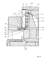
- Another embodiment of the seal provides a mechanical seal, which is arranged between the perforated plate and the ejector. Further refinements and arrangements of the seal are conceivable and are intended to be encompassed by the present invention. For example, it is thought to provide such a seal not only in the last perforated plate in conjunction with the ejector, but already in the previous perforated plates in conjunction with the rotary shaft. For here too it is to be prevented that coarse particles which do not correspond to the degree of comminution of the respective following perforated plate are nevertheless pressed through.
- the sealing ring must be able to radially adapt to the vibration of the rotary shaft, without that a material abrasion of the perforated plate or a wear of the seal is given.
- the individual seals are preferably made of plastic, ceramic or metal.
- plastic in particular glass fiber reinforced Teflon is preferred.
- Teflon As a metal, bronze is conceivable, since this is approved in the food industry. Further materials are conceivable and are intended to be encompassed by the present invention.
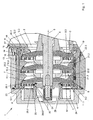
- FIG. 1 is of a device for crushing a crushed material, approximately corresponding to DE 39 15 409 C2 , Essentially only one crushing area 1 shown.
- This comminuting area 1 has an inlet opening 2 for the comminuted material and an ejection area 3, which in the present exemplary embodiment is covered by a hood 4.
- the comminuted material is conveyed from the inlet opening 2 to the ejection area 3 parallel to a longitudinal axis 5 of a rotary shaft 6, wherein the rotary shaft 6 protrudes through the inlet opening 2 into an approximately cylindrical housing 7, which is connected on the one hand with an inlet funnel 8 and on the other hand from the hood 4 is covered.
- Each quick set A, B and C consists of a perforated plate 9.1, 9.2 and 9.3 and a cutting head 10.1, 10.2 and 10.3, which Schneldklingen 11.1, 11.2 and 11.3.
- the cutting blades 11.1, 11.2 and 11.3 strip on the perforated plates 9.1, 9.2 and 9.3 along or are guided at a distance approximately equal to zero along the perforated plates 9.1, 9.2 and 9.3.
- Holes 12.3 in the perforated plate 9.3 are larger than holes 12.2 in the perforated plate 9.2. These are in turn larger than holes 12.1 in the perforated plate 9.1.
- the cutting heads 10.1 to 10.3 are non-rotatably mounted on the rotary shaft 6 and rotate with the rotary shaft 6 about the longitudinal axis 5.
- the perforated plates 9.1 to 9.3, however, are stationary in a sleeve-shaped actuating body 13 is arranged. This in turn is seated in the housing 7, wherein an externally threaded portion 14 engages the adjusting body 13 in an internally threaded portion 15 on the housing 7.
- this adjusting body 13 can thereby be moved in the direction of the longitudinal axis 5, wherein the perforated plates 9.1 to 9.3 taken and thereby the distance between each perforated plate 9.1 to 9.3 to the corresponding cutting blade 11.1 to 11.3 is changed.
- the rotation of the actuator 13 is preferably done via a worm gear not shown in detail or a stepper motor, on the output shaft, a corresponding pinion is seated, which is in engagement with a toothing 16 of a spur gear 17.
- This spur gear 17 is connected by appropriate screws 18 with the actuating body 13.
- the spacer ring 21.3 again forms an annular stop 20.2 for the perforated plate 9.2, which is also pressed by spring-loaded pressure pin 22.2 against this ring stop 20.2.
- the pressure pin 22.2 is located in a further spacer ring 21.2, which in turn forms a ring stop 20.1 for the perforated plate 9.1.
- an ejector 25 is provided, which is preferably rotatably connected to the rotary shaft 6.
- Crushed, in particular meat is introduced through the inlet opening 2 and enters the area of the cutting set C.
- the perforated plate 9.3 stands still while the cutting head 10.3 rotates with the rotary shaft 6, so that the material to be cut during the impressions in the holes 12.3 through the cutting blades 11.3 is crushed. In the holes 12.3 with the largest diameter, a rough pre-crushing takes place.
- the sausage meat reaches the cutting set B with the perforated plate 9.2 with the bores 12.2 of medium diameter. Again, the sausage meat is pressed into these holes 12.2 and simultaneously crushed by the cutting blades 11.2 moving along the perforated plate 9.2.
- the material to be crushed reaches the cutting set A, in which the perforated plate 9.1 is arranged with the holes 12.1 with the smallest diameter. Again, the sausage meat is pressed into these holes 12.1 and further crushed when pushed in by the cutting blades 11.1.
- the comminuted material enters the ejection region 3, in which it is fed by the ejector 25 of an ejection opening not shown in detail.
- the drive not shown in detail is set in action, so that it rotates about the teeth 16, the spur gear 17 and the spur gear 17 and the adjusting body 13.
- the internal thread 15 meshes in the external thread 14, so that the adjusting body 13 is moved along the longitudinal axis 5.
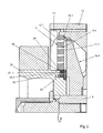
- a sealing ring 29.1 is provided in order to seal this gap 28, so that no uncut coarse fractions are pressed through it into the already comminuted material.
- This sealing ring 29.1 is defined in the inner diameter 26 of the perforated plate 9.1 and engages in a groove 30 of the ejector 25 and ensures an axial in both directions seal to the ejector 25 out.
- the sealing ring 29.1 has sufficient clearance in the groove 30, so that the sealing ring 29.1 can move radially in the groove 30 upon oscillation of the rotary shaft 6. The gap 28 can remain on this catfish without coarse particles can get into the already comminuted meat.
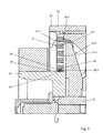
- FIG. 3 another embodiment of a gasket is shown.
- the sealing ring 29.2 sits firmly on the outer diameter 27 of the ejector 25 and engages in a groove 32 of the perforated plate 9.1.
- the sealing ring 29.2 again has sufficient clearance, so that the sealing ring 29.2 move radially in the groove 32 during the oscillation of the rotary shaft 6.
Landscapes
- Engineering & Computer Science (AREA)
- Food Science & Technology (AREA)
- Crushing And Pulverization Processes (AREA)
Claims (8)
- Dispositif de broyage d'un produit à broyer, en particulier pour le traitement de viande, au moyen d'au moins une plaque perforée (9.1, 9.2, 9.3) disposée dans un boîtier (7) et d'une lame tranchante (11.1, 11.2, 11.3) associée à cette dernière sur un arbre de rotation (6), dans lequel l'arbre de rotation (6) traverse la plaque perforée (9.1, 9.2, 9.3) et dans cette zone entre la plaque perforée (9.1, 9.2, 9.3) et l'arbre de rotation (6) est formé un interstice (28) en respectant une distance,
caractérisé par le fait
que l'interstice (28) entre la plaque perforée (9.1, 9.2, 9.3) et l'arbre de rotation (6) est obturé par un joint (29.1, 29.2, 29.3), le joint étant une bague d'étanchéité (29.1, 29.2, 29.3) et la bague d'étanchéité (29.1, 29.2, 29.3) étant disposée de manière mobile radialement. - Dispositif selon la revendication 1, caractérisé par le fait qu'entre la plaque perforée (9.1, 9.2, 9.3) et l'arbre de rotation (6) est prévu un éjecteur (25) qui est connecté de manière immobile en rotation à l'arbre de rotation (6) et qui forme par rapport à la plaque perforée (9.1, 9.2, 9.3) l'interstice (28) qui est, à son tour, obturé par la bague d'étanchéité (29.1, 29.2, 29.3).
- Dispositif selon au moins l'une des revendications 1 à 2, caractérisé par le fait que la bague d'étanchéité (29.1, 29.2, 29.3) est réalisée en matière plastique, céramique ou métal.
- Dispositif selon au moins l'une des revendications 1 à 3, caractérisé par le fait que la bague d'étanchéité (29.1, 29.2) est disposée dans une rainure (30, 32) ou dans une moulure de coin de l'arbre de rotation (6) ou de l'éjecteur (25).
- Dispositif selon la revendication 4, caractérisé par le fait que la bague d'étanchéité (29.1, 29.2) est maintenue dans la moulure de coin par une bague de retenue.
- Dispositif selon la revendication 4, caractérisé par le fait que la bague d'étanchéité (29.1) est fixée dans un diamètre intérieur (26) de la plaque perforée (9.1, 9.2, 9.3) et pénètre dans la rainure (30) ou la moulure de coin.
- Dispositif selon au moins l'une des revendications 1 à 3, caractérisé par le fait que la bague d'étanchéité (29.2) pénètre dans une rainure (32) ou moulure de coin de la plaque perforée (9.1, 9.2, 9.3).
- Dispositif selon la revendication 7, caractérisé par le fait que la bague d'étanchéité (29.2) est rendue solidaire de l'arbre de rotation (6) ou de l'éjecteur (25).
Applications Claiming Priority (2)
| Application Number | Priority Date | Filing Date | Title |
|---|---|---|---|
| DE200710025899 DE102007025899B4 (de) | 2007-06-01 | 2007-06-01 | Vorrichtung zum Zerkleinern eines Zerkleinerungsgutes |
| PCT/EP2008/004133 WO2008145310A1 (fr) | 2007-06-01 | 2008-05-23 | Dispositif de broyage d'un produit à broyer |
Publications (2)
| Publication Number | Publication Date |
|---|---|
| EP2164635A1 EP2164635A1 (fr) | 2010-03-24 |
| EP2164635B1 true EP2164635B1 (fr) | 2013-08-21 |
Family
ID=39760558
Family Applications (1)
| Application Number | Title | Priority Date | Filing Date |
|---|---|---|---|
| EP08758727.5A Active EP2164635B1 (fr) | 2007-06-01 | 2008-05-23 | Dispositif de broyage d'un produit à broyer |
Country Status (3)
| Country | Link |
|---|---|
| EP (1) | EP2164635B1 (fr) |
| DE (1) | DE102007025899B4 (fr) |
| WO (1) | WO2008145310A1 (fr) |
Cited By (1)
| Publication number | Priority date | Publication date | Assignee | Title |
|---|---|---|---|---|
| EP3984711A4 (fr) * | 2019-11-21 | 2022-08-24 | LG Chem, Ltd. | Hacheur composite pour hydrogel superabsorbant |
Families Citing this family (2)
| Publication number | Priority date | Publication date | Assignee | Title |
|---|---|---|---|---|
| DE102014216720A1 (de) | 2014-08-22 | 2016-02-25 | Karl Schnell Gmbh & Co. Kg | Zerkleinerungsmaschine zur Zerkleinerung eines Produkts |
| DE102022111847A1 (de) * | 2022-05-11 | 2023-11-16 | Inotec Gmbh Maschinenentwicklung U. Vertrieb | Vorrichtung zum Zerkleinern eines Zerkleinerungsgutes |
Family Cites Families (7)
| Publication number | Priority date | Publication date | Assignee | Title |
|---|---|---|---|---|
| DE1049729B (fr) | 1959-01-29 | |||
| DE641396C (de) * | 1934-01-03 | 1937-01-29 | Financ Mercuria S O F I M E Ho | Lochscheibe fuer Fleischwoelfe |
| US2694426A (en) * | 1951-10-23 | 1954-11-16 | Cincinnati Butchers Supply Co | Plate and spider assembly for material grinding machines |
| AT320464B (de) * | 1968-03-01 | 1975-02-10 | Vemag Verdener Masch App | Fleischzerkleinerungsmaschine mit mindestens einer Lochscheibe, vor der ein mehrarmiger Messerkopf umläuft |
| JPS62286560A (ja) * | 1986-06-04 | 1987-12-12 | 株式会社 平賀工作所 | チヨツパ− |
| DE3915409C2 (de) * | 1989-05-11 | 1998-09-17 | Inotec Gmbh Maschinenentwicklu | Zerkleinerungsmaschine, insbesondere für die fleischverarbeitende Industrie |
| DE19960409A1 (de) * | 1999-12-15 | 2001-06-21 | Inotec Gmbh Maschinenentwicklu | Vorrichtung zum Zerkleinern eines Zerkleinerungsgutes |
-
2007
- 2007-06-01 DE DE200710025899 patent/DE102007025899B4/de not_active Expired - Fee Related
-
2008
- 2008-05-23 WO PCT/EP2008/004133 patent/WO2008145310A1/fr not_active Ceased
- 2008-05-23 EP EP08758727.5A patent/EP2164635B1/fr active Active
Cited By (1)
| Publication number | Priority date | Publication date | Assignee | Title |
|---|---|---|---|---|
| EP3984711A4 (fr) * | 2019-11-21 | 2022-08-24 | LG Chem, Ltd. | Hacheur composite pour hydrogel superabsorbant |
Also Published As
| Publication number | Publication date |
|---|---|
| DE102007025899B4 (de) | 2011-03-03 |
| EP2164635A1 (fr) | 2010-03-24 |
| DE102007025899A1 (de) | 2008-12-04 |
| WO2008145310A1 (fr) | 2008-12-04 |
Similar Documents
| Publication | Publication Date | Title |
|---|---|---|
| DE1101745B (de) | Mahl- und Knetvorrichtung an Schneckenpressen fuer thermoplastische Massen | |
| EP2987557B1 (fr) | Machine de broyage d'un produit | |
| EP2189221A2 (fr) | Broyeur à billes à agitateur | |
| DE4223043C2 (de) | Extruder mit Drosselstempel | |
| EP3831494B1 (fr) | Broyeur à découper destiné au broyage par découpage des échantillons | |
| EP1237656B1 (fr) | Dispositif de broyage d'un materiau a broyer | |
| EP2164635B1 (fr) | Dispositif de broyage d'un produit à broyer | |
| DE102019106758A1 (de) | Schneidvorrichtung; Separierer; Verfahren zum Separieren von Lebensmittelbestandteilen mittels eines Separierers | |
| EP2036710B1 (fr) | Rotor pour presse rotative pour comprimés | |
| DE4037816A1 (de) | Walzwerk | |
| DE10026825C2 (de) | Zerkleinerungsvorrichtung | |
| EP0574694B1 (fr) | Outil de coupe pour machine à hacher des substances pâteuses | |
| DE102012008545A1 (de) | Vorrichtung zur Aufbereitung und Förderung von Biomassematerialien | |
| DE2154353A1 (de) | Schneidmaschine fuer fleischwaren oder dergl. (wolf) | |
| EP1132139B1 (fr) | Hachoir pour viande | |
| DE10312605B4 (de) | Einrichtung zum Trennen und Abfördern von Rohstoffen | |
| DE102004050810A1 (de) | Einwellige, kontinuierlich arbeitende Misch- und Knetmaschine | |
| DE202014105678U1 (de) | Lochscheibe, Schneidsystem damit sowie Zerkleinerungsmaschine | |
| DE19624574C1 (de) | Einrichtung zur Lagerung von Zubringer- und Arbeitsschnecken für Fleischwölfe und nach dem Wolfprinzip arbeitende Zerkleinerungsmaschinen | |
| DE19534674C2 (de) | Ringmesser für Fleischwölfe | |
| DE19942311C2 (de) | Spann- und Auszugssystem | |
| DE10237220C1 (de) | Kassetten-Schneidsatz | |
| DE102022111847A1 (de) | Vorrichtung zum Zerkleinern eines Zerkleinerungsgutes | |
| DE2002735C3 (de) | Mahlapparat | |
| DE700473C (de) | Mahl- und Zerkleinerungsvorrichtung |
Legal Events
| Date | Code | Title | Description |
|---|---|---|---|
| PUAI | Public reference made under article 153(3) epc to a published international application that has entered the european phase |
Free format text: ORIGINAL CODE: 0009012 |
|
| 17P | Request for examination filed |
Effective date: 20091229 |
|
| AK | Designated contracting states |
Kind code of ref document: A1 Designated state(s): AT BE BG CH CY CZ DE DK EE ES FI FR GB GR HR HU IE IS IT LI LT LU LV MC MT NL NO PL PT RO SE SI SK TR |
|
| AX | Request for extension of the european patent |
Extension state: AL BA MK RS |
|
| DAX | Request for extension of the european patent (deleted) | ||
| 17Q | First examination report despatched |
Effective date: 20110609 |
|
| GRAP | Despatch of communication of intention to grant a patent |
Free format text: ORIGINAL CODE: EPIDOSNIGR1 |
|
| INTG | Intention to grant announced |
Effective date: 20130422 |
|
| GRAS | Grant fee paid |
Free format text: ORIGINAL CODE: EPIDOSNIGR3 |
|
| GRAA | (expected) grant |
Free format text: ORIGINAL CODE: 0009210 |
|
| AK | Designated contracting states |
Kind code of ref document: B1 Designated state(s): AT BE BG CH CY CZ DE DK EE ES FI FR GB GR HR HU IE IS IT LI LT LU LV MC MT NL NO PL PT RO SE SI SK TR |
|
| REG | Reference to a national code |
Ref country code: GB Ref legal event code: FG4D Free format text: NOT ENGLISH |
|
| REG | Reference to a national code |
Ref country code: CH Ref legal event code: EP |
|
| REG | Reference to a national code |
Ref country code: AT Ref legal event code: REF Ref document number: 627741 Country of ref document: AT Kind code of ref document: T Effective date: 20130915 |
|
| REG | Reference to a national code |
Ref country code: IE Ref legal event code: FG4D Free format text: LANGUAGE OF EP DOCUMENT: GERMAN |
|
| REG | Reference to a national code |
Ref country code: DE Ref legal event code: R096 Ref document number: 502008010529 Country of ref document: DE Effective date: 20131017 |
|
| REG | Reference to a national code |
Ref country code: NL Ref legal event code: VDEP Effective date: 20130821 |
|
| REG | Reference to a national code |
Ref country code: LT Ref legal event code: MG4D |
|
| PG25 | Lapsed in a contracting state [announced via postgrant information from national office to epo] |
Ref country code: NO Free format text: LAPSE BECAUSE OF FAILURE TO SUBMIT A TRANSLATION OF THE DESCRIPTION OR TO PAY THE FEE WITHIN THE PRESCRIBED TIME-LIMIT Effective date: 20131121 Ref country code: CY Free format text: LAPSE BECAUSE OF FAILURE TO SUBMIT A TRANSLATION OF THE DESCRIPTION OR TO PAY THE FEE WITHIN THE PRESCRIBED TIME-LIMIT Effective date: 20130821 Ref country code: HR Free format text: LAPSE BECAUSE OF FAILURE TO SUBMIT A TRANSLATION OF THE DESCRIPTION OR TO PAY THE FEE WITHIN THE PRESCRIBED TIME-LIMIT Effective date: 20130821 Ref country code: SE Free format text: LAPSE BECAUSE OF FAILURE TO SUBMIT A TRANSLATION OF THE DESCRIPTION OR TO PAY THE FEE WITHIN THE PRESCRIBED TIME-LIMIT Effective date: 20130821 Ref country code: PT Free format text: LAPSE BECAUSE OF FAILURE TO SUBMIT A TRANSLATION OF THE DESCRIPTION OR TO PAY THE FEE WITHIN THE PRESCRIBED TIME-LIMIT Effective date: 20131223 Ref country code: LT Free format text: LAPSE BECAUSE OF FAILURE TO SUBMIT A TRANSLATION OF THE DESCRIPTION OR TO PAY THE FEE WITHIN THE PRESCRIBED TIME-LIMIT Effective date: 20130821 Ref country code: IS Free format text: LAPSE BECAUSE OF FAILURE TO SUBMIT A TRANSLATION OF THE DESCRIPTION OR TO PAY THE FEE WITHIN THE PRESCRIBED TIME-LIMIT Effective date: 20131221 |
|
| PG25 | Lapsed in a contracting state [announced via postgrant information from national office to epo] |
Ref country code: GR Free format text: LAPSE BECAUSE OF FAILURE TO SUBMIT A TRANSLATION OF THE DESCRIPTION OR TO PAY THE FEE WITHIN THE PRESCRIBED TIME-LIMIT Effective date: 20131122 Ref country code: LV Free format text: LAPSE BECAUSE OF FAILURE TO SUBMIT A TRANSLATION OF THE DESCRIPTION OR TO PAY THE FEE WITHIN THE PRESCRIBED TIME-LIMIT Effective date: 20130821 Ref country code: FI Free format text: LAPSE BECAUSE OF FAILURE TO SUBMIT A TRANSLATION OF THE DESCRIPTION OR TO PAY THE FEE WITHIN THE PRESCRIBED TIME-LIMIT Effective date: 20130821 Ref country code: PL Free format text: LAPSE BECAUSE OF FAILURE TO SUBMIT A TRANSLATION OF THE DESCRIPTION OR TO PAY THE FEE WITHIN THE PRESCRIBED TIME-LIMIT Effective date: 20130821 Ref country code: SI Free format text: LAPSE BECAUSE OF FAILURE TO SUBMIT A TRANSLATION OF THE DESCRIPTION OR TO PAY THE FEE WITHIN THE PRESCRIBED TIME-LIMIT Effective date: 20130821 |
|
| PG25 | Lapsed in a contracting state [announced via postgrant information from national office to epo] |
Ref country code: NL Free format text: LAPSE BECAUSE OF FAILURE TO SUBMIT A TRANSLATION OF THE DESCRIPTION OR TO PAY THE FEE WITHIN THE PRESCRIBED TIME-LIMIT Effective date: 20130821 Ref country code: RO Free format text: LAPSE BECAUSE OF FAILURE TO SUBMIT A TRANSLATION OF THE DESCRIPTION OR TO PAY THE FEE WITHIN THE PRESCRIBED TIME-LIMIT Effective date: 20130821 Ref country code: DK Free format text: LAPSE BECAUSE OF FAILURE TO SUBMIT A TRANSLATION OF THE DESCRIPTION OR TO PAY THE FEE WITHIN THE PRESCRIBED TIME-LIMIT Effective date: 20130821 Ref country code: EE Free format text: LAPSE BECAUSE OF FAILURE TO SUBMIT A TRANSLATION OF THE DESCRIPTION OR TO PAY THE FEE WITHIN THE PRESCRIBED TIME-LIMIT Effective date: 20130821 Ref country code: SK Free format text: LAPSE BECAUSE OF FAILURE TO SUBMIT A TRANSLATION OF THE DESCRIPTION OR TO PAY THE FEE WITHIN THE PRESCRIBED TIME-LIMIT Effective date: 20130821 Ref country code: CZ Free format text: LAPSE BECAUSE OF FAILURE TO SUBMIT A TRANSLATION OF THE DESCRIPTION OR TO PAY THE FEE WITHIN THE PRESCRIBED TIME-LIMIT Effective date: 20130821 |
|
| PG25 | Lapsed in a contracting state [announced via postgrant information from national office to epo] |
Ref country code: ES Free format text: LAPSE BECAUSE OF FAILURE TO SUBMIT A TRANSLATION OF THE DESCRIPTION OR TO PAY THE FEE WITHIN THE PRESCRIBED TIME-LIMIT Effective date: 20130821 Ref country code: IT Free format text: LAPSE BECAUSE OF FAILURE TO SUBMIT A TRANSLATION OF THE DESCRIPTION OR TO PAY THE FEE WITHIN THE PRESCRIBED TIME-LIMIT Effective date: 20130821 |
|
| PLBE | No opposition filed within time limit |
Free format text: ORIGINAL CODE: 0009261 |
|
| STAA | Information on the status of an ep patent application or granted ep patent |
Free format text: STATUS: NO OPPOSITION FILED WITHIN TIME LIMIT |
|
| 26N | No opposition filed |
Effective date: 20140522 |
|
| REG | Reference to a national code |
Ref country code: DE Ref legal event code: R097 Ref document number: 502008010529 Country of ref document: DE Effective date: 20140522 |
|
| PG25 | Lapsed in a contracting state [announced via postgrant information from national office to epo] |
Ref country code: LU Free format text: LAPSE BECAUSE OF FAILURE TO SUBMIT A TRANSLATION OF THE DESCRIPTION OR TO PAY THE FEE WITHIN THE PRESCRIBED TIME-LIMIT Effective date: 20140523 |
|
| REG | Reference to a national code |
Ref country code: CH Ref legal event code: PL |
|
| GBPC | Gb: european patent ceased through non-payment of renewal fee |
Effective date: 20140523 |
|
| PG25 | Lapsed in a contracting state [announced via postgrant information from national office to epo] |
Ref country code: CH Free format text: LAPSE BECAUSE OF NON-PAYMENT OF DUE FEES Effective date: 20140531 Ref country code: MC Free format text: LAPSE BECAUSE OF FAILURE TO SUBMIT A TRANSLATION OF THE DESCRIPTION OR TO PAY THE FEE WITHIN THE PRESCRIBED TIME-LIMIT Effective date: 20130821 Ref country code: LI Free format text: LAPSE BECAUSE OF NON-PAYMENT OF DUE FEES Effective date: 20140531 |
|
| REG | Reference to a national code |
Ref country code: IE Ref legal event code: MM4A |
|
| REG | Reference to a national code |
Ref country code: FR Ref legal event code: ST Effective date: 20150130 |
|
| PG25 | Lapsed in a contracting state [announced via postgrant information from national office to epo] |
Ref country code: IE Free format text: LAPSE BECAUSE OF NON-PAYMENT OF DUE FEES Effective date: 20140523 |
|
| PG25 | Lapsed in a contracting state [announced via postgrant information from national office to epo] |
Ref country code: FR Free format text: LAPSE BECAUSE OF NON-PAYMENT OF DUE FEES Effective date: 20140602 Ref country code: GB Free format text: LAPSE BECAUSE OF NON-PAYMENT OF DUE FEES Effective date: 20140523 |
|
| REG | Reference to a national code |
Ref country code: DE Ref legal event code: R082 Ref document number: 502008010529 Country of ref document: DE Representative=s name: PATENTANWAELTE UND RECHTSANWALT DR. WEISS, ARA, DE Ref country code: DE Ref legal event code: R082 Ref document number: 502008010529 Country of ref document: DE Representative=s name: PATENTANWAELTE UND RECHTSANWALT WEISS, ARAT & , DE |
|
| PG25 | Lapsed in a contracting state [announced via postgrant information from national office to epo] |
Ref country code: MT Free format text: LAPSE BECAUSE OF FAILURE TO SUBMIT A TRANSLATION OF THE DESCRIPTION OR TO PAY THE FEE WITHIN THE PRESCRIBED TIME-LIMIT Effective date: 20130821 |
|
| PG25 | Lapsed in a contracting state [announced via postgrant information from national office to epo] |
Ref country code: BG Free format text: LAPSE BECAUSE OF FAILURE TO SUBMIT A TRANSLATION OF THE DESCRIPTION OR TO PAY THE FEE WITHIN THE PRESCRIBED TIME-LIMIT Effective date: 20130821 |
|
| PG25 | Lapsed in a contracting state [announced via postgrant information from national office to epo] |
Ref country code: BE Free format text: LAPSE BECAUSE OF FAILURE TO SUBMIT A TRANSLATION OF THE DESCRIPTION OR TO PAY THE FEE WITHIN THE PRESCRIBED TIME-LIMIT Effective date: 20140531 Ref country code: HU Free format text: LAPSE BECAUSE OF FAILURE TO SUBMIT A TRANSLATION OF THE DESCRIPTION OR TO PAY THE FEE WITHIN THE PRESCRIBED TIME-LIMIT; INVALID AB INITIO Effective date: 20080523 Ref country code: TR Free format text: LAPSE BECAUSE OF FAILURE TO SUBMIT A TRANSLATION OF THE DESCRIPTION OR TO PAY THE FEE WITHIN THE PRESCRIBED TIME-LIMIT Effective date: 20130821 |
|
| PGFP | Annual fee paid to national office [announced via postgrant information from national office to epo] |
Ref country code: AT Payment date: 20250519 Year of fee payment: 18 |
|
| PGFP | Annual fee paid to national office [announced via postgrant information from national office to epo] |
Ref country code: DE Payment date: 20250728 Year of fee payment: 18 |