EP2189221A2 - Broyeur à billes à agitateur - Google Patents
Broyeur à billes à agitateur Download PDFInfo
- Publication number
- EP2189221A2 EP2189221A2 EP09006371A EP09006371A EP2189221A2 EP 2189221 A2 EP2189221 A2 EP 2189221A2 EP 09006371 A EP09006371 A EP 09006371A EP 09006371 A EP09006371 A EP 09006371A EP 2189221 A2 EP2189221 A2 EP 2189221A2
- Authority
- EP
- European Patent Office
- Prior art keywords
- grinding
- ball mill
- gap
- mill according
- agitator ball
- Prior art date
- Legal status (The legal status is an assumption and is not a legal conclusion. Google has not performed a legal analysis and makes no representation as to the accuracy of the status listed.)
- Granted
Links
Images


Classifications
-
- B—PERFORMING OPERATIONS; TRANSPORTING
- B02—CRUSHING, PULVERISING, OR DISINTEGRATING; PREPARATORY TREATMENT OF GRAIN FOR MILLING
- B02C—CRUSHING, PULVERISING, OR DISINTEGRATING IN GENERAL; MILLING GRAIN
- B02C17/00—Disintegrating by tumbling mills, i.e. mills having a container charged with the material to be disintegrated with or without special disintegrating members such as pebbles or balls
- B02C17/16—Mills in which a fixed container houses stirring means tumbling the charge
- B02C17/161—Arrangements for separating milling media and ground material
Definitions
- Agitator ball mill with a mixing vessel surrounding a stirring shaft, which is provided with a product inlet and a product outlet, wherein the Mahltospian located within the grinding container are activated by the rotation of the stirring shaft and retained by a separating or classifying device in the grinding chamber.
- This agitator ball mill goes out of the FIG. 1 of the DE 44 12 408 A1 out.
- This agitator ball mill has a double-walled grinding container, which is suitable for cooling.
- the coaxial with the grinding container arranged agitator shaft is connected to a gear and a drive.
- the grinding container has a Mahlguteinlcorro in its lid and centrally in its bottom a Mahlgutauslenfin.
- Mahltosenia located in the grinding chamber located on the stirrer shaft, provided with holes grinding discs, the Mahltos emotions in motion, whereby the energy that acts from the engine to the grinding discs, transfers to the Mahltos emotions.
- a separating device may also be provided.
- a vertically arranged agitator ball mill known from the DD 217 434 B1 is a vertically arranged agitator ball mill known.
- This agitator ball mill works with a stirring shaft to which a screw-shaped grinding element is attached.
- a pre-shredding device connected to the stirrer shaft, which consists of a crushing cone and a crushing ring fastened to the grinding container wall.
- the material to be ground or the material to be fed passes directly to the top side of the conveyor via a screw conveyor Brechkegels and from there into the crushing gap. After pre-shredding the material falls into the grinding container, where it is processed by the stirring shaft and the Mahl morn located in the grinding container.
- the filling level in the grinding container is monitored by a level measuring device. This is not possible with horizontally arranged mills and mills whose grinding space is fully utilized. In these cases, the material to be ground with the auxiliary grinding bodies reaches the area of the pre-shredding device.
- the aim of the invention is to combine a grinding and dispersing with a pre-crushing, which is largely protected against the wear that can cause the Mahlgut- / MahlosSystemgemisch.
- the goal is achieved with a stirred ball mill, in which after the product inlet a pre-shredding device is provided, which has a gap protection to the grinding chamber.
- Mahlosharmonics Due to the pressure prevailing in the grinding container and the percentage high Mahlos stresses circulllung in the grinding container, during the operation of the ball mill, Mahlos stresses reach the gap of Vorzerklein ceremoniess observed and here lead to wear or other adverse effects. Because of this, it is provided in an advantageous embodiment of the invention to protect the gap either by a dynamic or static gap protection.
- the gap protection may be advantageous to arrange the gap protection as a rotating or static part after the pre-shredder.
- the effect of the gap protection is improved according to the invention in that in this case a ring element is used, which is connected to the rotor of the pre-shredder.
- the ring element hurls the Mahltosisson radially in the region of the gap and simultaneously generates a negative pressure zone at the end of the gap transition to the grinding chamber whereby the product easily passes from the grinding zone into the grinding chamber.
- the ring element on the grinding chamber-side end of the grinding gap on a neck which may be designed wedge-shaped or nose-shaped.
- This design has the advantage that between the approach and the ring member, a distance can be maintained, which corresponds to 2 to 10 times the width of the grinding gap. This distance can be adapted in case of complicated construction of the attachment of the ring element, the size of the pre-shredded material or grinding auxiliary bodies.
- the static or dynamic ring element may not only ends radially at the grinding gap, but overlaps it in a ratio of 2 to 10 times the width of the grinding gap.
- the pre-shredding device consists of a rotating part and a stationary part, wherein the rotating part in turn is preferably in communication with the stirring shaft.
- the stationary part of the pre-shredding device communicates with the grinding container. This is particularly advantageous when this area of the grinding container is cooled. Even the cooling of one of the parts of the pre-shredding device keeps the product temperature constant during the pre-shredding.
- the toothed disks are arranged so that their faces directed towards the grinding chamber surfaces of the rotating and the stationary part of the pre-shredding simultaneously form the inlet-side Mahlraumbegrenzung.
- the gap formed by the stationary and the rotating part of the pre-shredding device is advantageously kept smaller than the diameter of the grinding auxiliary body located in the grinding chamber. In this case, a gap width of 0.2 - 2 mm is selected.
- either the rotating or the stationary part of the pre-shredding device can be axially adjustable, whereby the gap width can be changed during, before or after the production process.
- both the rotating and the stationary part of the pre-shredding device are axially adjustable via threads on the agitator shaft or on the grinding container. Lock nuts fix the corrected working position.
- the rotating and / or the stationary part of the pre-shredding device can be corrected by electrical or hydraulic actuators in their position.
- the initiatable via external command elements piston or electric drives thus allow a direct intervention on the pre-crushing and thus also an intervention on the fineness of the grinding process supplied product.
- FIG. 1 shows an agitator ball mill 10 with a grinding container 12 which is surrounded by a cooling jacket 14.
- Mahlosterrorism 18 are shown purely for demonstration only in a certain area of the grinding chamber are.
- the stirring shaft 20 In the grinding chamber itself is the stirring shaft 20, are placed on the grinding discs 22, with holes 24. The stirring shaft is rotated by a drive, not shown in rotation.
- a pre-classifier 26 which consists of a cage-like structure with a plurality of rods 28 and at least one closely spaced to the cage, provided with holes disc 30th can exist.
- a separator in the form of a sieve 32 downstream of the preclassifier.
- the product leaves the grinding chamber through the product outlet 34, which is arranged centrally in the grinding container bottom 36.
- the grinding vessel bottom itself is connected by screws 38 to a grinding vessel flange 40.
- the product inlet 42 Through the product inlet 42, the product passes into the inlet chamber 44, to which the seal 46 abuts, which in turn sits on the drive shaft 48.
- the pre-shredding device 50 From the inlet chamber, the product passes to the pre-shredding device 50, which is composed of a stationary part 52 and a rotating part 54.
- the standing part 52 overlaps both the coolant channel 56 and the grinding container lid 58.
- the standing and thus also the rotating part of the pre-crushing device may be displaced in the direction of the grinding chamber, so that the standing ring more intense by the coolant flowing in the coolant channel can be tempered.
- the grinding chamber facing surface 60 of the stationary part and the surface 62 of the rotating part form the inlet side grinding chamber boundary.
- the annular grinding gap has a width of 0.2 - 2 mm.
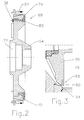
- FIG. 2 shows the arrangement of a dynamic gap protection 68, which is designed as a ring element 80.
- the gap protection 68 that is to say the ring element 80, is connected via screws 38 both to the rotating toothed disk 70 and to the rotating part 54 of a hub.
- the hub has central bores 72, by means of which the attachment to the agitator shaft 20 takes place.
- FIG. 3 shows the arrangement of a gap protection 68, which is adjacent only to the grinding gap.
- Its ring member 80 is made of wear-resistant material such as ceramic, high-alloy steel or the like.
- the ring member 80 does not overlap the gap in this embodiment.
- the proximity of the rotating part 70 extends to Mahlspalt and possibly the generated radial flow to keep the grinding gap 64 at its mouth to the grinding chamber 16 free of auxiliary grinding bodies.
- the ratio of the width a of the refining gap 64 to the radial overlap c through the shoulder is 1: 3.
- the axial distance b of the projection 74 to the end of the grinding gap 64 is compared to the width a of the grinding gap 64 in a ratio of 1: 4. This distance ratio allows a resistance-free entry of the pre-shredded product in the grinding chamber 16, since the approach 74 or its, the grinding gap 64 opposite surface does not inhibit the inflow.
- the projection 74 of the gap protection 68 is in this embodiment as a wedge-shaped or nose-shaped approach.
- the bevel reduces the wear on the circumference of the ring member 80 and minimizes turbulence.
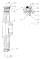
- FIGS. 6 and 7 shows a variant in which the gap protection 68 does not work dynamically but statically.
- the ring element 78 of the gap protection 68 bears against the stationary part 52 of the pre-shredding device 50 and is fixed by screws 76.
- the grinding gap 64 overlapping, radially inner side of the ring member 78 is wedge-shaped or nose-shaped.
- In the area of the milling gap 16 facing the end of the grinding gap 64 of the wedge-shaped or nose-shaped projection 74 is arranged at a distance b to the rotating part 54 of the pre-crushing device.
- the ratio of the radial overlap c of the projection 74 beyond the grinding gap 64 into the region of the rotating part is about 10: 1 compared to the width a of the grinding gap.
Landscapes
- Engineering & Computer Science (AREA)
- Food Science & Technology (AREA)
- Crushing And Grinding (AREA)
- Crushing And Pulverization Processes (AREA)
Priority Applications (1)
| Application Number | Priority Date | Filing Date | Title |
|---|---|---|---|
| PL09006371T PL2189221T3 (pl) | 2008-11-22 | 2009-05-12 | Młyn kulowy z mieszadłem |
Applications Claiming Priority (1)
| Application Number | Priority Date | Filing Date | Title |
|---|---|---|---|
| DE102008058585A DE102008058585A1 (de) | 2008-11-22 | 2008-11-22 | Rührwerkskugelmühle |
Publications (3)
| Publication Number | Publication Date |
|---|---|
| EP2189221A2 true EP2189221A2 (fr) | 2010-05-26 |
| EP2189221A3 EP2189221A3 (fr) | 2013-04-24 |
| EP2189221B1 EP2189221B1 (fr) | 2014-07-16 |
Family
ID=41466885
Family Applications (1)
| Application Number | Title | Priority Date | Filing Date |
|---|---|---|---|
| EP09006371.0A Active EP2189221B1 (fr) | 2008-11-22 | 2009-05-12 | Broyeur à billes à agitateur |
Country Status (7)
| Country | Link |
|---|---|
| US (1) | US8028943B2 (fr) |
| EP (1) | EP2189221B1 (fr) |
| BR (1) | BRPI0902612B1 (fr) |
| DE (1) | DE102008058585A1 (fr) |
| DK (1) | DK2189221T3 (fr) |
| ES (1) | ES2517940T3 (fr) |
| PL (1) | PL2189221T3 (fr) |
Cited By (5)
| Publication number | Priority date | Publication date | Assignee | Title |
|---|---|---|---|---|
| WO2012055388A3 (fr) * | 2010-10-27 | 2012-06-28 | Netzsch-Feinmahltechnik Gmbh | Broyeur à boulets avec agitateur |
| WO2014005570A3 (fr) * | 2012-07-05 | 2014-07-10 | Netzsch-Condux Mahltechnik Gmbh | Procédé permettant de faire fonctionner un broyeur agitateur à boulets et broyeur agitateur à boulets associé |
| CN105664768A (zh) * | 2016-03-30 | 2016-06-15 | 叶侃 | 一种陶瓷制品用粉末原料搅拌装置 |
| CN107952529A (zh) * | 2016-10-18 | 2018-04-24 | 威利A.巴霍芬公司 | 搅拌器式球磨机 |
| WO2022177525A1 (fr) * | 2021-02-19 | 2022-08-25 | Guelbeyaz Ilhan | Broyeur à géométrie en spirale |
Families Citing this family (16)
| Publication number | Priority date | Publication date | Assignee | Title |
|---|---|---|---|---|
| EP2327480A1 (fr) * | 2009-11-25 | 2011-06-01 | Willy A. Bachofen AG | Broyeur à billes à agitateur |
| DE102010053484A1 (de) * | 2010-12-04 | 2012-06-06 | Netzsch-Feinmahltechnik Gmbh | Dynamisches Element für die Trenneinrichtung einer Rührwerkskugelmühle |
| DE102011010527A1 (de) * | 2011-02-07 | 2012-08-09 | Lipp Mischtechnik Gmbh | Rührwerkskugelmühle |
| DE102011076157A1 (de) | 2011-05-20 | 2012-11-22 | Devetec Gmbh | Wärmekraftmaschine |
| CN102553684A (zh) * | 2011-12-31 | 2012-07-11 | 西安交通大学 | 一种刮铲搅拌卧式高能球磨机 |
| DE102012001417A1 (de) | 2012-01-26 | 2013-08-01 | Netzsch-Feinmahltechnik Gmbh | Verfahren zum Herstellen von Fettmassen |
| US9764329B2 (en) * | 2013-01-15 | 2017-09-19 | Aaron Engineered Process Equipment, Inc. | Rotary mill |
| CA2912729A1 (fr) | 2013-05-21 | 2014-11-27 | Flsmidth A/S | Procedes et appareil de surveillance en continu de l'usure dans des circuits de meulage |
| DE102013111762A1 (de) * | 2013-07-08 | 2015-01-08 | Netzsch-Feinmahltechnik Gmbh | Rührwerkskugelmühle mit Axialkanälen |
| DE102013111297A1 (de) * | 2013-10-14 | 2015-04-16 | Netzsch-Feinmahltechnik Gmbh | Vorzerkleinerungsvorrichtung für eine Kugelmühle oder Rührwerkskugelmühle und Kugelmühle mit Vorzerkleinerungseinrichtung |
| DE102013021757A1 (de) * | 2013-12-20 | 2015-06-25 | Netzsch Trockenmahltechnik Gmbh | Maschine mit fliegend gelagertem Rotor |
| DE102013021756A1 (de) * | 2013-12-20 | 2015-06-25 | Netzsch Trockenmahltechnik Gmbh | Mahlkörpermühle und Betriebsverfahren dafür |
| CN105618207A (zh) * | 2016-04-08 | 2016-06-01 | 中国神华能源股份有限公司 | 球磨机 |
| DE102018123096B4 (de) * | 2018-09-20 | 2022-01-27 | Netzsch Feinmahltechnik Gmbh | Rührwerkskugelmühle und Verfahren zum Betreiben einer Rührwerkskugelmühle |
| CN110694751A (zh) * | 2019-10-22 | 2020-01-17 | 上海琥崧智能科技股份有限公司 | 一种离心出料的卧式砂磨机及离心出料方法 |
| DE102022109275A1 (de) * | 2022-04-14 | 2023-10-19 | Netzsch-Feinmahltechnik Gmbh | Verfahren zum Herstellen einer pumpbaren Paste aus den Samen von Nuss- oder Steinfrüchten |
Citations (2)
| Publication number | Priority date | Publication date | Assignee | Title |
|---|---|---|---|---|
| DD217434B1 (de) | 1983-07-01 | 1987-06-24 | Dessau Zementanlagenbau Veb | Ruehrwerkskugelmuehle |
| DE4412408A1 (de) | 1994-04-11 | 1995-10-12 | Netzsch Erich Holding | Rührwerksmühle |
Family Cites Families (6)
| Publication number | Priority date | Publication date | Assignee | Title |
|---|---|---|---|---|
| JPS6028487Y2 (ja) * | 1981-03-16 | 1985-08-29 | 浅田鉄工株式会社 | グレインミル等におけるダイナミックセパレ−タ− |
| DE3249928C3 (de) * | 1982-12-10 | 1995-06-29 | Buehler Ag Geb | Rührwerksmühle |
| JPS63118950U (fr) * | 1987-01-26 | 1988-08-01 | ||
| JPS63122642U (fr) * | 1987-01-30 | 1988-08-09 | ||
| US5853132A (en) * | 1996-03-06 | 1998-12-29 | Fuji Photo Film Co., Ltd. | Dispersing machine |
| WO2006116338A2 (fr) * | 2005-04-25 | 2006-11-02 | Draiswerke, Inc. | Broyeur-agitateur a etages multiples |
-
2008
- 2008-11-22 DE DE102008058585A patent/DE102008058585A1/de not_active Withdrawn
-
2009
- 2009-05-12 DK DK09006371.0T patent/DK2189221T3/da active
- 2009-05-12 ES ES09006371.0T patent/ES2517940T3/es active Active
- 2009-05-12 EP EP09006371.0A patent/EP2189221B1/fr active Active
- 2009-05-12 PL PL09006371T patent/PL2189221T3/pl unknown
- 2009-07-28 BR BRPI0902612A patent/BRPI0902612B1/pt active IP Right Grant
- 2009-09-10 US US12/557,223 patent/US8028943B2/en active Active
Patent Citations (2)
| Publication number | Priority date | Publication date | Assignee | Title |
|---|---|---|---|---|
| DD217434B1 (de) | 1983-07-01 | 1987-06-24 | Dessau Zementanlagenbau Veb | Ruehrwerkskugelmuehle |
| DE4412408A1 (de) | 1994-04-11 | 1995-10-12 | Netzsch Erich Holding | Rührwerksmühle |
Cited By (11)
| Publication number | Priority date | Publication date | Assignee | Title |
|---|---|---|---|---|
| WO2012055388A3 (fr) * | 2010-10-27 | 2012-06-28 | Netzsch-Feinmahltechnik Gmbh | Broyeur à boulets avec agitateur |
| US8702023B2 (en) | 2010-10-27 | 2014-04-22 | Netzch-Feinmahltechnik GmbH | Stirring ball mill |
| RU2571069C2 (ru) * | 2010-10-27 | 2015-12-20 | Неч-Файнмальтехник Гмбх | Шаровая мельница с мешалкой |
| WO2014005570A3 (fr) * | 2012-07-05 | 2014-07-10 | Netzsch-Condux Mahltechnik Gmbh | Procédé permettant de faire fonctionner un broyeur agitateur à boulets et broyeur agitateur à boulets associé |
| US9505008B2 (en) | 2012-07-05 | 2016-11-29 | Netzsch Trockenmahltechnik Gmbh | Method for operating an agitator bead mill and agitator bead mill therefor |
| CN105664768A (zh) * | 2016-03-30 | 2016-06-15 | 叶侃 | 一种陶瓷制品用粉末原料搅拌装置 |
| CN105664768B (zh) * | 2016-03-30 | 2018-07-06 | 肇庆市富强陶瓷有限公司 | 一种陶瓷制品用粉末原料搅拌装置 |
| CN107952529A (zh) * | 2016-10-18 | 2018-04-24 | 威利A.巴霍芬公司 | 搅拌器式球磨机 |
| CN107952529B (zh) * | 2016-10-18 | 2020-06-05 | 威利A.巴霍芬公司 | 搅拌器式球磨机 |
| US10792665B2 (en) | 2016-10-18 | 2020-10-06 | Willy A. Bachofen Ag | Agitator ball mill |
| WO2022177525A1 (fr) * | 2021-02-19 | 2022-08-25 | Guelbeyaz Ilhan | Broyeur à géométrie en spirale |
Also Published As
| Publication number | Publication date |
|---|---|
| EP2189221A3 (fr) | 2013-04-24 |
| US8028943B2 (en) | 2011-10-04 |
| ES2517940T3 (es) | 2014-11-04 |
| EP2189221B1 (fr) | 2014-07-16 |
| US20100127108A1 (en) | 2010-05-27 |
| PL2189221T3 (pl) | 2015-01-30 |
| BRPI0902612B1 (pt) | 2020-04-07 |
| BRPI0902612A2 (pt) | 2010-09-14 |
| DE102008058585A1 (de) | 2010-05-27 |
| DK2189221T3 (da) | 2014-10-06 |
Similar Documents
| Publication | Publication Date | Title |
|---|---|---|
| EP2189221B1 (fr) | Broyeur à billes à agitateur | |
| EP2178642B1 (fr) | Broyeur agitateur | |
| DE602005005487T2 (de) | Dispergiervorrichtung | |
| DE2020649C3 (de) | Rührwerksmühle zum Dispergieren von Festkörperteilchen in einem flüssigen Träger | |
| DE1482391B1 (de) | Ruehrwerksmuehle | |
| EP2178643B1 (fr) | Broyeur agitateur | |
| EP2036613A2 (fr) | Broyeur à billes à agitateur | |
| EP0376001B1 (fr) | Broyeur agitateur avec dispositif de séparation dans une cage rotative | |
| DE10011579B4 (de) | Rührwerksmühle | |
| EP3584011A1 (fr) | Broyeur à découper destiné au broyage par découpage des échantillons | |
| DE102009020708A1 (de) | Vorrichtung zum Zerkleinern von Aufgabegut | |
| DE19819967A1 (de) | Rührwerksmühle | |
| DE3844380C1 (en) | Agitator mill with separating device in a rotating cage | |
| EP2484450B2 (fr) | Broyeur agitateur à billes | |
| DE102018009873A1 (de) | Schneidewerk für eine Abwasser-Tauchpumpe | |
| EP0645179B1 (fr) | Moulin à frottement et malaxeur contenant ledit moulin | |
| DE2633225A1 (de) | Muehle | |
| EP3271076A1 (fr) | Dispositif de fragmentation | |
| EP2176001B1 (fr) | Broyeur agitateur | |
| DE102021101527B4 (de) | Rührwerksmühle | |
| LU102840B1 (de) | Schneidring für mit Feststoff belastete Flüssigkeit einer Pumpe | |
| WO2008145310A1 (fr) | Dispositif de broyage d'un produit à broyer | |
| DE1461012B2 (de) | Vorrichtung zum zerfasern von papierstoff | |
| DE3811483A1 (de) | Kugelmuehle | |
| DE106932C (fr) |
Legal Events
| Date | Code | Title | Description |
|---|---|---|---|
| PUAI | Public reference made under article 153(3) epc to a published international application that has entered the european phase |
Free format text: ORIGINAL CODE: 0009012 |
|
| AK | Designated contracting states |
Kind code of ref document: A2 Designated state(s): AT BE BG CH CY CZ DE DK EE ES FI FR GB GR HR HU IE IS IT LI LT LU LV MC MK MT NL NO PL PT RO SE SI SK TR |
|
| AX | Request for extension of the european patent |
Extension state: AL BA RS |
|
| PUAL | Search report despatched |
Free format text: ORIGINAL CODE: 0009013 |
|
| AK | Designated contracting states |
Kind code of ref document: A3 Designated state(s): AT BE BG CH CY CZ DE DK EE ES FI FR GB GR HR HU IE IS IT LI LT LU LV MC MK MT NL NO PL PT RO SE SI SK TR |
|
| AX | Request for extension of the european patent |
Extension state: AL BA RS |
|
| RIC1 | Information provided on ipc code assigned before grant |
Ipc: B02C 17/16 20060101AFI20130318BHEP |
|
| 17P | Request for examination filed |
Effective date: 20130516 |
|
| 17Q | First examination report despatched |
Effective date: 20131104 |
|
| GRAP | Despatch of communication of intention to grant a patent |
Free format text: ORIGINAL CODE: EPIDOSNIGR1 |
|
| GRAS | Grant fee paid |
Free format text: ORIGINAL CODE: EPIDOSNIGR3 |
|
| INTG | Intention to grant announced |
Effective date: 20140325 |
|
| RIN1 | Information on inventor provided before grant (corrected) |
Inventor name: HARBS, THERON |
|
| GRAA | (expected) grant |
Free format text: ORIGINAL CODE: 0009210 |
|
| AK | Designated contracting states |
Kind code of ref document: B1 Designated state(s): AT BE BG CH CY CZ DE DK EE ES FI FR GB GR HR HU IE IS IT LI LT LU LV MC MK MT NL NO PL PT RO SE SI SK TR |
|
| REG | Reference to a national code |
Ref country code: GB Ref legal event code: FG4D Free format text: NOT ENGLISH |
|
| REG | Reference to a national code |
Ref country code: CH Ref legal event code: EP |
|
| REG | Reference to a national code |
Ref country code: IE Ref legal event code: FG4D Free format text: LANGUAGE OF EP DOCUMENT: GERMAN |
|
| REG | Reference to a national code |
Ref country code: AT Ref legal event code: REF Ref document number: 677249 Country of ref document: AT Kind code of ref document: T Effective date: 20140815 |
|
| REG | Reference to a national code |
Ref country code: DE Ref legal event code: R096 Ref document number: 502009009639 Country of ref document: DE Effective date: 20140821 |
|
| REG | Reference to a national code |
Ref country code: DK Ref legal event code: T3 Effective date: 20140930 |
|
| REG | Reference to a national code |
Ref country code: ES Ref legal event code: FG2A Ref document number: 2517940 Country of ref document: ES Kind code of ref document: T3 Effective date: 20141104 |
|
| REG | Reference to a national code |
Ref country code: NL Ref legal event code: T3 |
|
| REG | Reference to a national code |
Ref country code: LT Ref legal event code: MG4D |
|
| PG25 | Lapsed in a contracting state [announced via postgrant information from national office to epo] |
Ref country code: NO Free format text: LAPSE BECAUSE OF FAILURE TO SUBMIT A TRANSLATION OF THE DESCRIPTION OR TO PAY THE FEE WITHIN THE PRESCRIBED TIME-LIMIT Effective date: 20141016 Ref country code: BG Free format text: LAPSE BECAUSE OF FAILURE TO SUBMIT A TRANSLATION OF THE DESCRIPTION OR TO PAY THE FEE WITHIN THE PRESCRIBED TIME-LIMIT Effective date: 20141016 Ref country code: SE Free format text: LAPSE BECAUSE OF FAILURE TO SUBMIT A TRANSLATION OF THE DESCRIPTION OR TO PAY THE FEE WITHIN THE PRESCRIBED TIME-LIMIT Effective date: 20140716 Ref country code: LT Free format text: LAPSE BECAUSE OF FAILURE TO SUBMIT A TRANSLATION OF THE DESCRIPTION OR TO PAY THE FEE WITHIN THE PRESCRIBED TIME-LIMIT Effective date: 20140716 Ref country code: PT Free format text: LAPSE BECAUSE OF FAILURE TO SUBMIT A TRANSLATION OF THE DESCRIPTION OR TO PAY THE FEE WITHIN THE PRESCRIBED TIME-LIMIT Effective date: 20141117 Ref country code: FI Free format text: LAPSE BECAUSE OF FAILURE TO SUBMIT A TRANSLATION OF THE DESCRIPTION OR TO PAY THE FEE WITHIN THE PRESCRIBED TIME-LIMIT Effective date: 20140716 Ref country code: GR Free format text: LAPSE BECAUSE OF FAILURE TO SUBMIT A TRANSLATION OF THE DESCRIPTION OR TO PAY THE FEE WITHIN THE PRESCRIBED TIME-LIMIT Effective date: 20141017 |
|
| REG | Reference to a national code |
Ref country code: PL Ref legal event code: T3 |
|
| PG25 | Lapsed in a contracting state [announced via postgrant information from national office to epo] |
Ref country code: IS Free format text: LAPSE BECAUSE OF FAILURE TO SUBMIT A TRANSLATION OF THE DESCRIPTION OR TO PAY THE FEE WITHIN THE PRESCRIBED TIME-LIMIT Effective date: 20141116 Ref country code: CY Free format text: LAPSE BECAUSE OF FAILURE TO SUBMIT A TRANSLATION OF THE DESCRIPTION OR TO PAY THE FEE WITHIN THE PRESCRIBED TIME-LIMIT Effective date: 20140716 Ref country code: LV Free format text: LAPSE BECAUSE OF FAILURE TO SUBMIT A TRANSLATION OF THE DESCRIPTION OR TO PAY THE FEE WITHIN THE PRESCRIBED TIME-LIMIT Effective date: 20140716 |
|
| REG | Reference to a national code |
Ref country code: DE Ref legal event code: R097 Ref document number: 502009009639 Country of ref document: DE |
|
| PG25 | Lapsed in a contracting state [announced via postgrant information from national office to epo] |
Ref country code: RO Free format text: LAPSE BECAUSE OF FAILURE TO SUBMIT A TRANSLATION OF THE DESCRIPTION OR TO PAY THE FEE WITHIN THE PRESCRIBED TIME-LIMIT Effective date: 20140716 Ref country code: CZ Free format text: LAPSE BECAUSE OF FAILURE TO SUBMIT A TRANSLATION OF THE DESCRIPTION OR TO PAY THE FEE WITHIN THE PRESCRIBED TIME-LIMIT Effective date: 20140716 Ref country code: EE Free format text: LAPSE BECAUSE OF FAILURE TO SUBMIT A TRANSLATION OF THE DESCRIPTION OR TO PAY THE FEE WITHIN THE PRESCRIBED TIME-LIMIT Effective date: 20140716 Ref country code: SK Free format text: LAPSE BECAUSE OF FAILURE TO SUBMIT A TRANSLATION OF THE DESCRIPTION OR TO PAY THE FEE WITHIN THE PRESCRIBED TIME-LIMIT Effective date: 20140716 |
|
| PLBE | No opposition filed within time limit |
Free format text: ORIGINAL CODE: 0009261 |
|
| STAA | Information on the status of an ep patent application or granted ep patent |
Free format text: STATUS: NO OPPOSITION FILED WITHIN TIME LIMIT |
|
| 26N | No opposition filed |
Effective date: 20150417 |
|
| PG25 | Lapsed in a contracting state [announced via postgrant information from national office to epo] |
Ref country code: SI Free format text: LAPSE BECAUSE OF FAILURE TO SUBMIT A TRANSLATION OF THE DESCRIPTION OR TO PAY THE FEE WITHIN THE PRESCRIBED TIME-LIMIT Effective date: 20140716 |
|
| PG25 | Lapsed in a contracting state [announced via postgrant information from national office to epo] |
Ref country code: LU Free format text: LAPSE BECAUSE OF FAILURE TO SUBMIT A TRANSLATION OF THE DESCRIPTION OR TO PAY THE FEE WITHIN THE PRESCRIBED TIME-LIMIT Effective date: 20150512 Ref country code: MC Free format text: LAPSE BECAUSE OF FAILURE TO SUBMIT A TRANSLATION OF THE DESCRIPTION OR TO PAY THE FEE WITHIN THE PRESCRIBED TIME-LIMIT Effective date: 20140716 |
|
| REG | Reference to a national code |
Ref country code: IE Ref legal event code: MM4A |
|
| PG25 | Lapsed in a contracting state [announced via postgrant information from national office to epo] |
Ref country code: IE Free format text: LAPSE BECAUSE OF NON-PAYMENT OF DUE FEES Effective date: 20150512 |
|
| REG | Reference to a national code |
Ref country code: FR Ref legal event code: PLFP Year of fee payment: 8 |
|
| PG25 | Lapsed in a contracting state [announced via postgrant information from national office to epo] |
Ref country code: MT Free format text: LAPSE BECAUSE OF FAILURE TO SUBMIT A TRANSLATION OF THE DESCRIPTION OR TO PAY THE FEE WITHIN THE PRESCRIBED TIME-LIMIT Effective date: 20140716 |
|
| REG | Reference to a national code |
Ref country code: FR Ref legal event code: PLFP Year of fee payment: 9 |
|
| PG25 | Lapsed in a contracting state [announced via postgrant information from national office to epo] |
Ref country code: HU Free format text: LAPSE BECAUSE OF FAILURE TO SUBMIT A TRANSLATION OF THE DESCRIPTION OR TO PAY THE FEE WITHIN THE PRESCRIBED TIME-LIMIT; INVALID AB INITIO Effective date: 20090512 |
|
| PG25 | Lapsed in a contracting state [announced via postgrant information from national office to epo] |
Ref country code: HR Free format text: LAPSE BECAUSE OF FAILURE TO SUBMIT A TRANSLATION OF THE DESCRIPTION OR TO PAY THE FEE WITHIN THE PRESCRIBED TIME-LIMIT Effective date: 20140716 Ref country code: BE Free format text: LAPSE BECAUSE OF NON-PAYMENT OF DUE FEES Effective date: 20150531 |
|
| REG | Reference to a national code |
Ref country code: FR Ref legal event code: PLFP Year of fee payment: 10 |
|
| PG25 | Lapsed in a contracting state [announced via postgrant information from national office to epo] |
Ref country code: MK Free format text: LAPSE BECAUSE OF FAILURE TO SUBMIT A TRANSLATION OF THE DESCRIPTION OR TO PAY THE FEE WITHIN THE PRESCRIBED TIME-LIMIT Effective date: 20140716 |
|
| PGFP | Annual fee paid to national office [announced via postgrant information from national office to epo] |
Ref country code: NL Payment date: 20230525 Year of fee payment: 15 Ref country code: IT Payment date: 20230529 Year of fee payment: 15 Ref country code: FR Payment date: 20230523 Year of fee payment: 15 Ref country code: ES Payment date: 20230601 Year of fee payment: 15 Ref country code: DK Payment date: 20230523 Year of fee payment: 15 Ref country code: DE Payment date: 20230525 Year of fee payment: 15 Ref country code: CH Payment date: 20230602 Year of fee payment: 15 |
|
| PGFP | Annual fee paid to national office [announced via postgrant information from national office to epo] |
Ref country code: TR Payment date: 20230509 Year of fee payment: 15 Ref country code: PL Payment date: 20230420 Year of fee payment: 15 Ref country code: AT Payment date: 20230524 Year of fee payment: 15 |
|
| PGFP | Annual fee paid to national office [announced via postgrant information from national office to epo] |
Ref country code: GB Payment date: 20230526 Year of fee payment: 15 |