EP2036613A2 - Broyeur à billes à agitateur - Google Patents
Broyeur à billes à agitateur Download PDFInfo
- Publication number
- EP2036613A2 EP2036613A2 EP08014106A EP08014106A EP2036613A2 EP 2036613 A2 EP2036613 A2 EP 2036613A2 EP 08014106 A EP08014106 A EP 08014106A EP 08014106 A EP08014106 A EP 08014106A EP 2036613 A2 EP2036613 A2 EP 2036613A2
- Authority
- EP
- European Patent Office
- Prior art keywords
- ball mill
- mill according
- agitator ball
- spiral
- agitator
- Prior art date
- Legal status (The legal status is an assumption and is not a legal conclusion. Google has not performed a legal analysis and makes no representation as to the accuracy of the status listed.)
- Granted
Links
- 238000003756 stirring Methods 0.000 title claims abstract description 24
- 238000006073 displacement reaction Methods 0.000 claims 1
- 230000003068 static effect Effects 0.000 claims 1
- 239000000463 material Substances 0.000 abstract description 13
- 235000012054 meals Nutrition 0.000 abstract 4
- 238000003801 milling Methods 0.000 abstract 1
- 238000000926 separation method Methods 0.000 description 7
- 230000000694 effects Effects 0.000 description 4
- 230000035515 penetration Effects 0.000 description 3
- 230000010006 flight Effects 0.000 description 2
- 230000036961 partial effect Effects 0.000 description 2
- 230000015572 biosynthetic process Effects 0.000 description 1
- 238000001816 cooling Methods 0.000 description 1
- 230000007423 decrease Effects 0.000 description 1
- 230000001419 dependent effect Effects 0.000 description 1
- 238000010438 heat treatment Methods 0.000 description 1
- 230000002401 inhibitory effect Effects 0.000 description 1
- 239000002184 metal Substances 0.000 description 1
- 230000002829 reductive effect Effects 0.000 description 1
- 230000002441 reversible effect Effects 0.000 description 1
- 238000007789 sealing Methods 0.000 description 1
- 239000000126 substance Substances 0.000 description 1
Images


Classifications
-
- B—PERFORMING OPERATIONS; TRANSPORTING
- B02—CRUSHING, PULVERISING, OR DISINTEGRATING; PREPARATORY TREATMENT OF GRAIN FOR MILLING
- B02C—CRUSHING, PULVERISING, OR DISINTEGRATING IN GENERAL; MILLING GRAIN
- B02C17/00—Disintegrating by tumbling mills, i.e. mills having a container charged with the material to be disintegrated with or without special disintegrating members such as pebbles or balls
- B02C17/16—Mills in which a fixed container houses stirring means tumbling the charge
- B02C17/161—Arrangements for separating milling media and ground material
-
- B—PERFORMING OPERATIONS; TRANSPORTING
- B02—CRUSHING, PULVERISING, OR DISINTEGRATING; PREPARATORY TREATMENT OF GRAIN FOR MILLING
- B02C—CRUSHING, PULVERISING, OR DISINTEGRATING IN GENERAL; MILLING GRAIN
- B02C17/00—Disintegrating by tumbling mills, i.e. mills having a container charged with the material to be disintegrated with or without special disintegrating members such as pebbles or balls
Definitions
- the invention relates to a stirred ball mill with a cylindrical grinding container having at least one Mahlguteinlraw and at least one Mahlgutauslenfin, wherein in the Mahlgut actuallyer a connected to a drive agitator shaft is arranged, which transfers a portion of the drive energy to Mahltos stresses that are loosely arranged in the grinding container and a before the Mahlgutauslledge arranged separation device.
- This separating device has a plurality of arcuate conveying or wing elements, which are arranged between two discs on.
- the wing members extend from the outer edge of the discs toward the center thereof, the members terminating in part at different distances from the Mahlgutauslenfin.
- the object of the invention is therefore to improve a separator even for KleinstmahlMech to the effect that even during the start-up and shut-down phase of the agitator ball mill penetration of Mahlos phenomena is prevented in the Mahlgutauslenfin.
- the invention thus provides a stirred ball mill, comprising a cylindrical grinding container having at least one grinding stock inlet and a grinding stock outlet, wherein the grinding container horizontally arranged as shown in the embodiment has a stirring shaft connected to a drive, which transmits a part of the drive energy to the grinding auxiliary body.
- a separator is used which has at least one spiral.
- the separation alignment consists of two spirals.
- a further preferred embodiment provides that the spirals are arranged at a constant distance from each other.
- Another preferred embodiment of the invention is provided to achieve a self-locking of Mahltos emotions each other when the separator is stopped.
- the spiral extends with its radially inner end directly to the Mahlgutauslescu.
- the Mahlgutauslenfin may extend on both sides of the longitudinal center of the spiral.
- the width of the spiral (s) is at least one third of its diameter.
- the spiral sits between the agitator shaft surface and the longitudinal axis of the agitator shaft.
- the stirring shaft which has radial openings in this area.
- the slot-shaped openings are inclined counter to the direction of rotation of the stirring shaft.
- the openings of the agitator shaft may be advantageous to make the openings of the agitator shaft tangential or asymmetrical to its longitudinal axis.
- the stirring shaft in the spiral / n with stirring elements consisting of Rhakstäben or cams and which are offset by at least 45 ° to each other.
- the spiral / n contrary to the normal design, in which they consist of sheet metal, consist of individual spaced-apart rods and webs. These rods and webs can, but need not be touching, connected to each other.
- the diameter of the spiral (s) is at least 30% of the grinding chamber diameter.
- the diameter of the spiral (s) is at least 30% of the diameter of the cavity in the agitator shaft.
- the separating device is used with a drive arranged independently of the stirring shaft, it may be advantageous if the spirals are inserted between two full-surface sealing surfaces.
- the side faces located on the spirals end surfaces have openings through which Mahlos stresses can flow back into the grinding chamber.
- the radially outer ends of the spirals are offset by at least 90 ° to each other.
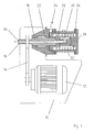
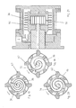
- the agitator ball mill consists of a housing 10 in which a drive 12 is seated in the form of an electric motor.
- the drive is connected by means of a drive belt 14 with a drive shaft 16 in connection.
- This drive shaft passes into the bearing shaft 18, which in turn is connected to the agitator shaft 20.
- the grinding chamber 48 is bounded by the grinding container 26 which surrounds the stirring shaft 20 and the grinding container bottom 28.
- the separating device 30, with which the Mahltosharm 54 are separated from the ground material, sitting within the Stirring shaft 20. For cooling or heating of the grinding container this is double-walled with a coolable or heatable jacket 32 surrounded.
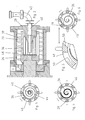
- FIG. 2 shows the arrangement of a spiral 36, within the agitator shaft 20, in the surface of stirring rods 38 are used.
- the millbase flows here centrally from the grinding container 26 via a line 40, which merges into a pipeline 42.
- the FIG. 3 discloses the design of a spiral used, for example, for separating the auxiliary grinding bodies from the material to be ground.
- This spiral 36 extends here over 720 °.
- the grinding material flowing into the spiral passes through the pipeline 40 to the grinding stock outlet.
- the grinding auxiliary bodies are conveyed back into the grinding chamber 48 via passages 46 in the agitating shaft before they enter the worm gear 44.
- FIGS. 4 and 5 Examples of the arrangement of the spiral can be seen, in which the spirals 36 each extend through 360 °.
- the spiral consists of rods, in FIG. 6 from triangular-shaped profiles. Through this in the In the widest sense, rough surfaces of the spirals are said to support the self-locking effect that occurs during stoppage of the stirrer shaft. To increase this self-locking effect, the design of the spiral in FIGS. 4 and 6 be increased by extending the spiral.
- FIG. 5 illustrates the design of the passages 46, the lateral surfaces 50 are directed tangentially to the central axis of the agitator shaft.
- FIG. 7 is a separator 30 can be seen, which has one or more spirals 36. Depending on how long the path of the individual Mahlos stresses in the spiral, the fewer turns must make the separate drive 52 to accomplish a penetration of Mahlos stresses in the Mahlgutauslescu.
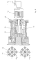
- FIGS. 9 and 10 let recognize that the separator operates with a right- and left-handed spiral. It does not matter in the end that the spiral rotates in the opposite direction of rotation as the agitator shaft. The function of the spiral is independent of the direction of rotation of the stirrer shaft.
- FIG. 11 agitator ball mill rotates the separator 30 synchronously with the agitator shaft 20.
- the spiral 36 of the separator abuts with its left side to the stirring shaft and is clamped to the right side by a clamping element 56 with the stirring shaft.
- Centrally in the longitudinal center of the spiral is located in the region of the longitudinal axis of the agitator shaft 20 of the inlet 58 of the Mahlgutauslasses 34th Die
- FIG. 12 illustrates in this case, the length of the spiral 36, which here covers a range of 630 °.
- the design of the separator according to the FIGS. 13, 14 and 15 is especially designed for high-viscosity substances. Since in high-viscosity materials, the forces of resistance between the product and the Mahlos stressesn are very high, you need a longer way to separate the Mahlos redesign, why in FIG. 13 two spirals 36 are provided.
- the outer surfaces of the spirals act as deflectors until the beginning of the other screw. This means that these surfaces 60 produce a pulsating effect in the direction of the grinding chamber and thus already cause a deflection of the auxiliary grinding bodies in the direction of the grinding chamber at the periphery of the separating device.
- the auxiliary grinding bodies are constantly forced to return to the grinding chamber by the frictional forces on the spiral walls and the reverse conveying direction.
- FIG. 14 will be the use of in the FIG. 13 described spirals 36 shown.
- the separator is located here directly on the front side of the overhung agitator shaft 20.
- the product flows centrally via the agitator shaft 20 and bearing shaft 18 from.
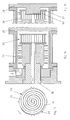
- the grinding container bottom 28 has a projection 60.
- the spiral 36 is open in the direction of projection so that Mahlospian can flow back into the grinding chamber 48 on a short path.
- the outer region of the spiral 36 is bounded by a ring 62.
- FIGS. 16 and 17 show separation devices with two spirals, each extending over a range of 500 ° and 560 °.
- the two spirals have screw flights with constant wall distance A.
- the separating device 30 rotates together with the agitator shaft 20, wherein the product outlet takes place through the agitator shaft 20 and bearing shaft 18.
- the separator is a projection 60 designed, which is used for flow formation.
- the agitator shaft has in this embodiment, no grinding pins 31, but cam 62.
- FIGS. 18, 19, 20 and 21 demonstrate the location and design of separators with spirals whose spacing is as in FIG. 18 constant, in FIG. 19 reducing and in FIG. 20 are executed widening.
- the FIG. 18 corresponds to the here FIG. 16 in which the distance A remains constant over the entire arrangement of the two spirals 36.
- the spirals 36 are arranged so that the distance B is reduced from the grinding chamber to the outlet.
- This variant is used in particular when low-viscosity material is used and thus it must be expected that the agitator ball mill will be put out of operation for a short time. Due to the reducing distance between the two spirals, the self-inhibiting effect between the spiral walls and the auxiliary grinding bodies is enhanced. Due to the arrangement of the two spirals according to FIG. 20 you can achieve a faster flow of the product after separation from the Mahlos stressesn.
- the illustrated geometry of the two spirals 36 shows that the distance C increases in the direction from the grinding chamber to the Mahlgutauslenfin.
- FIG. 23 Another possibility for conveying auxiliary grinding bodies from the area of the separating device laterally out of the spiral passages back into the grinding chamber is in FIG. 23 shown.
- the separating device 30 is seated within a cavity 64 which is open on one side within the agitator shaft.
- the spiral 36 is held by the agitator shaft 20.
- the ring has a slot 68 through which the Mahlos emotions can flow via the cavity 64 back into the grinding chamber.
- the processed ground material leaves the grinding chamber from the central region within the spiral / s 36 via a dip tube 70. As out FIG. 22 shows, this separator has only one spiral 36.
Landscapes
- Engineering & Computer Science (AREA)
- Food Science & Technology (AREA)
- Crushing And Grinding (AREA)
- Powder Metallurgy (AREA)
- Mixers Of The Rotary Stirring Type (AREA)
Applications Claiming Priority (1)
| Application Number | Priority Date | Filing Date | Title |
|---|---|---|---|
| DE102007043670A DE102007043670A1 (de) | 2007-09-13 | 2007-09-13 | Rührwerkskugelmühle |
Publications (3)
| Publication Number | Publication Date |
|---|---|
| EP2036613A2 true EP2036613A2 (fr) | 2009-03-18 |
| EP2036613A3 EP2036613A3 (fr) | 2009-11-25 |
| EP2036613B1 EP2036613B1 (fr) | 2010-11-24 |
Family
ID=40076825
Family Applications (1)
| Application Number | Title | Priority Date | Filing Date |
|---|---|---|---|
| EP08014106A Active EP2036613B1 (fr) | 2007-09-13 | 2008-08-07 | Broyeur à billes à agitateur |
Country Status (10)
| Country | Link |
|---|---|
| US (1) | US7845589B2 (fr) |
| EP (1) | EP2036613B1 (fr) |
| JP (1) | JP4879947B2 (fr) |
| KR (1) | KR101554464B1 (fr) |
| CN (1) | CN101385989B (fr) |
| AT (1) | ATE489172T1 (fr) |
| BR (1) | BRPI0803553B1 (fr) |
| DE (2) | DE102007043670A1 (fr) |
| ES (1) | ES2355415T3 (fr) |
| TW (1) | TWI410281B (fr) |
Cited By (4)
| Publication number | Priority date | Publication date | Assignee | Title |
|---|---|---|---|---|
| EP2327480A1 (fr) * | 2009-11-25 | 2011-06-01 | Willy A. Bachofen AG | Broyeur à billes à agitateur |
| FR3018807A1 (fr) * | 2014-03-20 | 2015-09-25 | Herakles | Procede d'obtention de charges de cristaux d'hexanitrohexaazaisowurtzitane (cl20) de granulometrie monomodale submicronique, lesdites charges et leur utilisation comme charges d'ensemencement |
| CN107755023A (zh) * | 2016-08-22 | 2018-03-06 | 深圳市叁星飞荣机械有限公司 | 一种卧式封闭无机械密封介质搅拌磨 |
| EP3441144A4 (fr) * | 2016-05-09 | 2019-05-08 | Boyee (Shenzhen) Industrial Technology Co., Ltd. | Séparateur de broyage du type à agitation et dispositif de broyage |
Families Citing this family (23)
| Publication number | Priority date | Publication date | Assignee | Title |
|---|---|---|---|---|
| IT1404138B1 (it) * | 2010-05-06 | 2013-11-15 | Lico Spa | Mulino per la macinazione, in particolare l'atomizzazione, di uno o piu' materiali |
| DE102010053484A1 (de) | 2010-12-04 | 2012-06-06 | Netzsch-Feinmahltechnik Gmbh | Dynamisches Element für die Trenneinrichtung einer Rührwerkskugelmühle |
| CN103041897B (zh) * | 2011-10-17 | 2015-02-25 | 谢小飞 | 介质搅拌磨的叠装涡轮式料珠分离器 |
| US9206051B2 (en) | 2012-03-30 | 2015-12-08 | Scott Murray | Apparatus for mechanical exfoliation of particulate materials |
| CN102872936B (zh) * | 2012-09-26 | 2015-05-13 | 广州派勒机械设备有限公司 | 纳米级动态分离式研磨机 |
| CN102974432B (zh) * | 2012-12-26 | 2015-12-02 | 广州派勒机械设备有限公司 | 一种动态分离出料式研磨机 |
| CA2912729A1 (fr) | 2013-05-21 | 2014-11-27 | Flsmidth A/S | Procedes et appareil de surveillance en continu de l'usure dans des circuits de meulage |
| DE102013111762A1 (de) | 2013-07-08 | 2015-01-08 | Netzsch-Feinmahltechnik Gmbh | Rührwerkskugelmühle mit Axialkanälen |
| DE102013021757A1 (de) * | 2013-12-20 | 2015-06-25 | Netzsch Trockenmahltechnik Gmbh | Maschine mit fliegend gelagertem Rotor |
| DE102013021756A1 (de) * | 2013-12-20 | 2015-06-25 | Netzsch Trockenmahltechnik Gmbh | Mahlkörpermühle und Betriebsverfahren dafür |
| CN104001446B (zh) * | 2014-05-01 | 2016-05-11 | 铜陵创慧科技咨询服务有限公司 | 一种组装式涡轮旋转分散器 |
| CN104759324A (zh) * | 2015-04-03 | 2015-07-08 | 东莞市亿富机械科技有限公司 | 一种纳米研磨机 |
| DE102015105804A1 (de) * | 2015-04-16 | 2016-10-20 | Netzsch-Feinmahltechnik Gmbh | Rührwerkskugelmühle |
| DE102015107789B3 (de) | 2015-05-19 | 2016-07-07 | Netzsch-Feinmahltechnik Gmbh | Rührwerkskugelmühle und Verfahren zum Betreiben einer Rührwerkskugelmühle |
| CN104959196A (zh) * | 2015-06-29 | 2015-10-07 | 广州派勒机械设备有限公司 | 具有双重分离系统的超级砂磨机 |
| CN105396650A (zh) * | 2015-09-22 | 2016-03-16 | 广州派勒机械设备有限公司 | 无筛网式智能纳米研磨系统 |
| CN105289857B (zh) * | 2015-11-09 | 2017-11-21 | 河南师范大学 | 纳米级动态离心分离装置 |
| CN109365066B (zh) * | 2017-11-18 | 2020-10-09 | 深圳市叁星飞荣机械有限公司 | 一种具有多级分离与分级功能的立式介质搅拌磨 |
| DE102018123096B4 (de) * | 2018-09-20 | 2022-01-27 | Netzsch Feinmahltechnik Gmbh | Rührwerkskugelmühle und Verfahren zum Betreiben einer Rührwerkskugelmühle |
| CN111215199A (zh) * | 2019-07-26 | 2020-06-02 | 湖北迈兆机械有限公司 | 一种球磨离心分离装置 |
| CN111250224B (zh) * | 2019-07-26 | 2023-11-24 | 湖北迈兆机械有限公司 | 离心式研磨分离器 |
| CN112958228A (zh) * | 2021-03-14 | 2021-06-15 | 上海琥崧智能科技股份有限公司 | 一种用于研磨机筛网分离装置 |
| DE102022125879A1 (de) | 2022-10-07 | 2024-04-18 | Netzsch-Feinmahltechnik Gmbh | Rührwerksmühle |
Citations (1)
| Publication number | Priority date | Publication date | Assignee | Title |
|---|---|---|---|---|
| EP1468739A1 (fr) | 2003-04-15 | 2004-10-20 | Willy A. Bachofen AG | Broyeur agitateur à billes |
Family Cites Families (2)
| Publication number | Priority date | Publication date | Assignee | Title |
|---|---|---|---|---|
| GB1129188A (en) * | 1966-06-23 | 1968-10-02 | Smidth & Co As F L | Grinding process and mill for carrying out the process |
| US5333804A (en) * | 1993-08-20 | 1994-08-02 | Premier Mill Corp. | Agitator mill |
-
2007
- 2007-09-13 DE DE102007043670A patent/DE102007043670A1/de not_active Withdrawn
-
2008
- 2008-08-07 ES ES08014106T patent/ES2355415T3/es active Active
- 2008-08-07 AT AT08014106T patent/ATE489172T1/de active
- 2008-08-07 EP EP08014106A patent/EP2036613B1/fr active Active
- 2008-08-07 DE DE502008001873T patent/DE502008001873D1/de active Active
- 2008-08-26 TW TW097132546A patent/TWI410281B/zh active
- 2008-08-28 KR KR1020080084561A patent/KR101554464B1/ko active IP Right Grant
- 2008-09-05 US US12/205,252 patent/US7845589B2/en active Active
- 2008-09-11 CN CN200810212990XA patent/CN101385989B/zh active Active
- 2008-09-12 JP JP2008235173A patent/JP4879947B2/ja active Active
- 2008-09-15 BR BRPI0803553-9A patent/BRPI0803553B1/pt active IP Right Grant
Patent Citations (1)
| Publication number | Priority date | Publication date | Assignee | Title |
|---|---|---|---|---|
| EP1468739A1 (fr) | 2003-04-15 | 2004-10-20 | Willy A. Bachofen AG | Broyeur agitateur à billes |
Cited By (5)
| Publication number | Priority date | Publication date | Assignee | Title |
|---|---|---|---|---|
| EP2327480A1 (fr) * | 2009-11-25 | 2011-06-01 | Willy A. Bachofen AG | Broyeur à billes à agitateur |
| EP2327479A1 (fr) * | 2009-11-25 | 2011-06-01 | Willy A. Bachofen AG | Broyeur à billes à agitateur |
| FR3018807A1 (fr) * | 2014-03-20 | 2015-09-25 | Herakles | Procede d'obtention de charges de cristaux d'hexanitrohexaazaisowurtzitane (cl20) de granulometrie monomodale submicronique, lesdites charges et leur utilisation comme charges d'ensemencement |
| EP3441144A4 (fr) * | 2016-05-09 | 2019-05-08 | Boyee (Shenzhen) Industrial Technology Co., Ltd. | Séparateur de broyage du type à agitation et dispositif de broyage |
| CN107755023A (zh) * | 2016-08-22 | 2018-03-06 | 深圳市叁星飞荣机械有限公司 | 一种卧式封闭无机械密封介质搅拌磨 |
Also Published As
| Publication number | Publication date |
|---|---|
| KR20090028412A (ko) | 2009-03-18 |
| ES2355415T3 (es) | 2011-03-25 |
| JP4879947B2 (ja) | 2012-02-22 |
| DE102007043670A1 (de) | 2009-04-02 |
| TW200916194A (en) | 2009-04-16 |
| EP2036613A3 (fr) | 2009-11-25 |
| ATE489172T1 (de) | 2010-12-15 |
| US7845589B2 (en) | 2010-12-07 |
| DE502008001873D1 (de) | 2011-01-05 |
| TWI410281B (zh) | 2013-10-01 |
| KR101554464B1 (ko) | 2015-09-21 |
| BRPI0803553A2 (pt) | 2009-05-05 |
| CN101385989A (zh) | 2009-03-18 |
| JP2009066595A (ja) | 2009-04-02 |
| CN101385989B (zh) | 2013-02-06 |
| US20090072060A1 (en) | 2009-03-19 |
| EP2036613B1 (fr) | 2010-11-24 |
| BRPI0803553B1 (pt) | 2020-09-29 |
Similar Documents
| Publication | Publication Date | Title |
|---|---|---|
| EP2036613B1 (fr) | Broyeur à billes à agitateur | |
| EP2189221B1 (fr) | Broyeur à billes à agitateur | |
| EP3019276B1 (fr) | Broyeur agitateur à billes avec des canaux axials | |
| EP3311922B1 (fr) | Broyeur à billes à agitateur | |
| EP2155353B1 (fr) | Séparateur à vis à pression | |
| EP2886198B1 (fr) | Procédé de fonctionnement pour un broyeur à billes et broyeur à billes associé | |
| EP1899074B1 (fr) | Centrifugeuse a vis | |
| WO2011004014A1 (fr) | Séparateur à axe rotatif vertical | |
| EP1724022A1 (fr) | Broyeur à agitateur | |
| DE4438841C2 (de) | Pumpe mit einer Schneideinrichtung | |
| DE2143401C2 (de) | Pumpe | |
| DE10064828B4 (de) | Rührwerksmühle | |
| EP0448100B1 (fr) | Broyeur-mélangeur | |
| DE4402609C1 (de) | Rührwerkskugelmühle | |
| DE102009003268B3 (de) | Gewürzmühle und Gewürzbehälter mit einer solchen | |
| WO1998028077A1 (fr) | Machine de reduction en morceaux pourvue d'un emulgateur | |
| EP0645179B1 (fr) | Moulin à frottement et malaxeur contenant ledit moulin | |
| CH700016B1 (de) | Gleitringdichtung. | |
| DE102015106458B4 (de) | Zellenradschleuse | |
| EP2821143B1 (fr) | Mélangeur-couteau pour un hachoir | |
| WO2011117090A1 (fr) | Centrifugeuse à vis sans fin à bol plein | |
| EP1344944A1 (fr) | Pompe centrifuge avec un dispositif de broyage | |
| EP3515602B1 (fr) | Broyeur fin | |
| DE1803266C3 (de) | Vorrichtung zum Entfernen von Flüssigkeiten aus elastomerem oder polymerem Material | |
| EP1724021A1 (fr) | Broyeur à agitateur |
Legal Events
| Date | Code | Title | Description |
|---|---|---|---|
| PUAI | Public reference made under article 153(3) epc to a published international application that has entered the european phase |
Free format text: ORIGINAL CODE: 0009012 |
|
| AK | Designated contracting states |
Kind code of ref document: A2 Designated state(s): AT BE BG CH CY CZ DE DK EE ES FI FR GB GR HR HU IE IS IT LI LT LU LV MC MT NL NO PL PT RO SE SI SK TR |
|
| AX | Request for extension of the european patent |
Extension state: AL BA MK RS |
|
| PUAL | Search report despatched |
Free format text: ORIGINAL CODE: 0009013 |
|
| AK | Designated contracting states |
Kind code of ref document: A3 Designated state(s): AT BE BG CH CY CZ DE DK EE ES FI FR GB GR HR HU IE IS IT LI LT LU LV MC MT NL NO PL PT RO SE SI SK TR |
|
| AX | Request for extension of the european patent |
Extension state: AL BA MK RS |
|
| 17P | Request for examination filed |
Effective date: 20100525 |
|
| 17Q | First examination report despatched |
Effective date: 20100622 |
|
| AKX | Designation fees paid |
Designated state(s): AT BE BG CH CY CZ DE DK EE ES FI FR GB GR HR HU IE IS IT LI LT LU LV MC MT NL NO PL PT RO SE SI SK TR |
|
| GRAP | Despatch of communication of intention to grant a patent |
Free format text: ORIGINAL CODE: EPIDOSNIGR1 |
|
| GRAS | Grant fee paid |
Free format text: ORIGINAL CODE: EPIDOSNIGR3 |
|
| GRAA | (expected) grant |
Free format text: ORIGINAL CODE: 0009210 |
|
| AK | Designated contracting states |
Kind code of ref document: B1 Designated state(s): AT BE BG CH CY CZ DE DK EE ES FI FR GB GR HR HU IE IS IT LI LT LU LV MC MT NL NO PL PT RO SE SI SK TR |
|
| REG | Reference to a national code |
Ref country code: GB Ref legal event code: FG4D Free format text: NOT ENGLISH |
|
| REG | Reference to a national code |
Ref country code: CH Ref legal event code: EP |
|
| REG | Reference to a national code |
Ref country code: IE Ref legal event code: FG4D |
|
| REF | Corresponds to: |
Ref document number: 502008001873 Country of ref document: DE Date of ref document: 20110105 Kind code of ref document: P |
|
| REG | Reference to a national code |
Ref country code: CH Ref legal event code: NV Representative=s name: PATENTANWAELTE SCHAAD, BALASS, MENZL & PARTNER AG |
|
| REG | Reference to a national code |
Ref country code: NL Ref legal event code: VDEP Effective date: 20101124 |
|
| REG | Reference to a national code |
Ref country code: ES Ref legal event code: FG2A Ref document number: 2355415 Country of ref document: ES Kind code of ref document: T3 Effective date: 20110325 |
|
| LTIE | Lt: invalidation of european patent or patent extension |
Effective date: 20101124 |
|
| PG25 | Lapsed in a contracting state [announced via postgrant information from national office to epo] |
Ref country code: LT Free format text: LAPSE BECAUSE OF FAILURE TO SUBMIT A TRANSLATION OF THE DESCRIPTION OR TO PAY THE FEE WITHIN THE PRESCRIBED TIME-LIMIT Effective date: 20101124 Ref country code: NO Free format text: LAPSE BECAUSE OF FAILURE TO SUBMIT A TRANSLATION OF THE DESCRIPTION OR TO PAY THE FEE WITHIN THE PRESCRIBED TIME-LIMIT Effective date: 20110224 |
|
| PG25 | Lapsed in a contracting state [announced via postgrant information from national office to epo] |
Ref country code: LV Free format text: LAPSE BECAUSE OF FAILURE TO SUBMIT A TRANSLATION OF THE DESCRIPTION OR TO PAY THE FEE WITHIN THE PRESCRIBED TIME-LIMIT Effective date: 20101124 Ref country code: NL Free format text: LAPSE BECAUSE OF FAILURE TO SUBMIT A TRANSLATION OF THE DESCRIPTION OR TO PAY THE FEE WITHIN THE PRESCRIBED TIME-LIMIT Effective date: 20101124 Ref country code: SI Free format text: LAPSE BECAUSE OF FAILURE TO SUBMIT A TRANSLATION OF THE DESCRIPTION OR TO PAY THE FEE WITHIN THE PRESCRIBED TIME-LIMIT Effective date: 20101124 Ref country code: BG Free format text: LAPSE BECAUSE OF FAILURE TO SUBMIT A TRANSLATION OF THE DESCRIPTION OR TO PAY THE FEE WITHIN THE PRESCRIBED TIME-LIMIT Effective date: 20110224 Ref country code: PT Free format text: LAPSE BECAUSE OF FAILURE TO SUBMIT A TRANSLATION OF THE DESCRIPTION OR TO PAY THE FEE WITHIN THE PRESCRIBED TIME-LIMIT Effective date: 20110324 Ref country code: SE Free format text: LAPSE BECAUSE OF FAILURE TO SUBMIT A TRANSLATION OF THE DESCRIPTION OR TO PAY THE FEE WITHIN THE PRESCRIBED TIME-LIMIT Effective date: 20101124 Ref country code: FI Free format text: LAPSE BECAUSE OF FAILURE TO SUBMIT A TRANSLATION OF THE DESCRIPTION OR TO PAY THE FEE WITHIN THE PRESCRIBED TIME-LIMIT Effective date: 20101124 Ref country code: CY Free format text: LAPSE BECAUSE OF FAILURE TO SUBMIT A TRANSLATION OF THE DESCRIPTION OR TO PAY THE FEE WITHIN THE PRESCRIBED TIME-LIMIT Effective date: 20101124 Ref country code: HR Free format text: LAPSE BECAUSE OF FAILURE TO SUBMIT A TRANSLATION OF THE DESCRIPTION OR TO PAY THE FEE WITHIN THE PRESCRIBED TIME-LIMIT Effective date: 20101124 Ref country code: IS Free format text: LAPSE BECAUSE OF FAILURE TO SUBMIT A TRANSLATION OF THE DESCRIPTION OR TO PAY THE FEE WITHIN THE PRESCRIBED TIME-LIMIT Effective date: 20110324 |
|
| REG | Reference to a national code |
Ref country code: IE Ref legal event code: FD4D |
|
| PG25 | Lapsed in a contracting state [announced via postgrant information from national office to epo] |
Ref country code: GR Free format text: LAPSE BECAUSE OF FAILURE TO SUBMIT A TRANSLATION OF THE DESCRIPTION OR TO PAY THE FEE WITHIN THE PRESCRIBED TIME-LIMIT Effective date: 20110225 |
|
| PG25 | Lapsed in a contracting state [announced via postgrant information from national office to epo] |
Ref country code: EE Free format text: LAPSE BECAUSE OF FAILURE TO SUBMIT A TRANSLATION OF THE DESCRIPTION OR TO PAY THE FEE WITHIN THE PRESCRIBED TIME-LIMIT Effective date: 20101124 Ref country code: IE Free format text: LAPSE BECAUSE OF FAILURE TO SUBMIT A TRANSLATION OF THE DESCRIPTION OR TO PAY THE FEE WITHIN THE PRESCRIBED TIME-LIMIT Effective date: 20101124 Ref country code: CZ Free format text: LAPSE BECAUSE OF FAILURE TO SUBMIT A TRANSLATION OF THE DESCRIPTION OR TO PAY THE FEE WITHIN THE PRESCRIBED TIME-LIMIT Effective date: 20101124 |
|
| PG25 | Lapsed in a contracting state [announced via postgrant information from national office to epo] |
Ref country code: RO Free format text: LAPSE BECAUSE OF FAILURE TO SUBMIT A TRANSLATION OF THE DESCRIPTION OR TO PAY THE FEE WITHIN THE PRESCRIBED TIME-LIMIT Effective date: 20101124 Ref country code: DK Free format text: LAPSE BECAUSE OF FAILURE TO SUBMIT A TRANSLATION OF THE DESCRIPTION OR TO PAY THE FEE WITHIN THE PRESCRIBED TIME-LIMIT Effective date: 20101124 Ref country code: SK Free format text: LAPSE BECAUSE OF FAILURE TO SUBMIT A TRANSLATION OF THE DESCRIPTION OR TO PAY THE FEE WITHIN THE PRESCRIBED TIME-LIMIT Effective date: 20101124 Ref country code: PL Free format text: LAPSE BECAUSE OF FAILURE TO SUBMIT A TRANSLATION OF THE DESCRIPTION OR TO PAY THE FEE WITHIN THE PRESCRIBED TIME-LIMIT Effective date: 20101124 |
|
| PLBE | No opposition filed within time limit |
Free format text: ORIGINAL CODE: 0009261 |
|
| STAA | Information on the status of an ep patent application or granted ep patent |
Free format text: STATUS: NO OPPOSITION FILED WITHIN TIME LIMIT |
|
| 26N | No opposition filed |
Effective date: 20110825 |
|
| REG | Reference to a national code |
Ref country code: DE Ref legal event code: R097 Ref document number: 502008001873 Country of ref document: DE Effective date: 20110825 |
|
| PG25 | Lapsed in a contracting state [announced via postgrant information from national office to epo] |
Ref country code: IT Free format text: LAPSE BECAUSE OF FAILURE TO SUBMIT A TRANSLATION OF THE DESCRIPTION OR TO PAY THE FEE WITHIN THE PRESCRIBED TIME-LIMIT Effective date: 20101124 Ref country code: MT Free format text: LAPSE BECAUSE OF FAILURE TO SUBMIT A TRANSLATION OF THE DESCRIPTION OR TO PAY THE FEE WITHIN THE PRESCRIBED TIME-LIMIT Effective date: 20101124 |
|
| BERE | Be: lapsed |
Owner name: NETZSCH-FEINMAHLTECHNIK G.M.B.H. Effective date: 20110831 |
|
| PG25 | Lapsed in a contracting state [announced via postgrant information from national office to epo] |
Ref country code: MC Free format text: LAPSE BECAUSE OF NON-PAYMENT OF DUE FEES Effective date: 20110831 |
|
| REG | Reference to a national code |
Ref country code: FR Ref legal event code: ST Effective date: 20120430 |
|
| PG25 | Lapsed in a contracting state [announced via postgrant information from national office to epo] |
Ref country code: BE Free format text: LAPSE BECAUSE OF NON-PAYMENT OF DUE FEES Effective date: 20110831 |
|
| PG25 | Lapsed in a contracting state [announced via postgrant information from national office to epo] |
Ref country code: FR Free format text: LAPSE BECAUSE OF NON-PAYMENT OF DUE FEES Effective date: 20110831 |
|
| GBPC | Gb: european patent ceased through non-payment of renewal fee |
Effective date: 20120807 |
|
| PG25 | Lapsed in a contracting state [announced via postgrant information from national office to epo] |
Ref country code: LU Free format text: LAPSE BECAUSE OF NON-PAYMENT OF DUE FEES Effective date: 20110807 |
|
| PG25 | Lapsed in a contracting state [announced via postgrant information from national office to epo] |
Ref country code: GB Free format text: LAPSE BECAUSE OF NON-PAYMENT OF DUE FEES Effective date: 20120807 |
|
| PG25 | Lapsed in a contracting state [announced via postgrant information from national office to epo] |
Ref country code: TR Free format text: LAPSE BECAUSE OF FAILURE TO SUBMIT A TRANSLATION OF THE DESCRIPTION OR TO PAY THE FEE WITHIN THE PRESCRIBED TIME-LIMIT Effective date: 20101124 |
|
| PG25 | Lapsed in a contracting state [announced via postgrant information from national office to epo] |
Ref country code: HU Free format text: LAPSE BECAUSE OF FAILURE TO SUBMIT A TRANSLATION OF THE DESCRIPTION OR TO PAY THE FEE WITHIN THE PRESCRIBED TIME-LIMIT Effective date: 20101124 |
|
| REG | Reference to a national code |
Ref country code: AT Ref legal event code: MM01 Ref document number: 489172 Country of ref document: AT Kind code of ref document: T Effective date: 20130807 |
|
| PG25 | Lapsed in a contracting state [announced via postgrant information from national office to epo] |
Ref country code: AT Free format text: LAPSE BECAUSE OF NON-PAYMENT OF DUE FEES Effective date: 20130807 |
|
| PGFP | Annual fee paid to national office [announced via postgrant information from national office to epo] |
Ref country code: ES Payment date: 20230901 Year of fee payment: 16 Ref country code: CH Payment date: 20230902 Year of fee payment: 16 |
|
| PGFP | Annual fee paid to national office [announced via postgrant information from national office to epo] |
Ref country code: DE Payment date: 20230831 Year of fee payment: 16 |